Facies, Sequence Framework, and Evolution of Rudist Buildups, Shu’aiba Formation, Saudi Arabia Nasser Mohammad Al-Ghamdi Thesis submitted to the Faculty of the Virginia Polytechnic Institute and State University in partial fulfillment of the requirements for the degree of MASTER OF SCIENCE in GEOLOGICAL SCIENCES APPROVED: J.Fred Read, Chairman K.A. Eriksson R.D. Law May 19, 2006 Blacksburg, Virginia Keywords: Lower Cretaceous, Aptian, Sequence Stratigraphy, Arabian Plate, Paleoclimate, Eustasy

Welcome message from author
This document is posted to help you gain knowledge. Please leave a comment to let me know what you think about it! Share it to your friends and learn new things together.
Transcript
Facies, Sequence Framework, and Evolution of Rudist Buildups, Shu’aiba Formation, Saudi Arabia
Nasser Mohammad Al-Ghamdi
Thesis submitted to the Faculty of the Virginia Polytechnic Institute and State University
in partial fulfillment of the requirements for the degree of
MASTER OF SCIENCE
in
GEOLOGICAL SCIENCES
APPROVED:
J.Fred Read, Chairman K.A. Eriksson
R.D. Law
May 19, 2006
Blacksburg, Virginia
Keywords: Lower Cretaceous, Aptian, Sequence Stratigraphy, Arabian Plate, Paleoclimate, Eustasy
ii
Facies, Sequence Framework, and Evolution of Rudist Buildups, Shu’aiba Formation, Saudi Arabia
Nasser Mohammad Al-Ghamdi
(ABSTRACT)
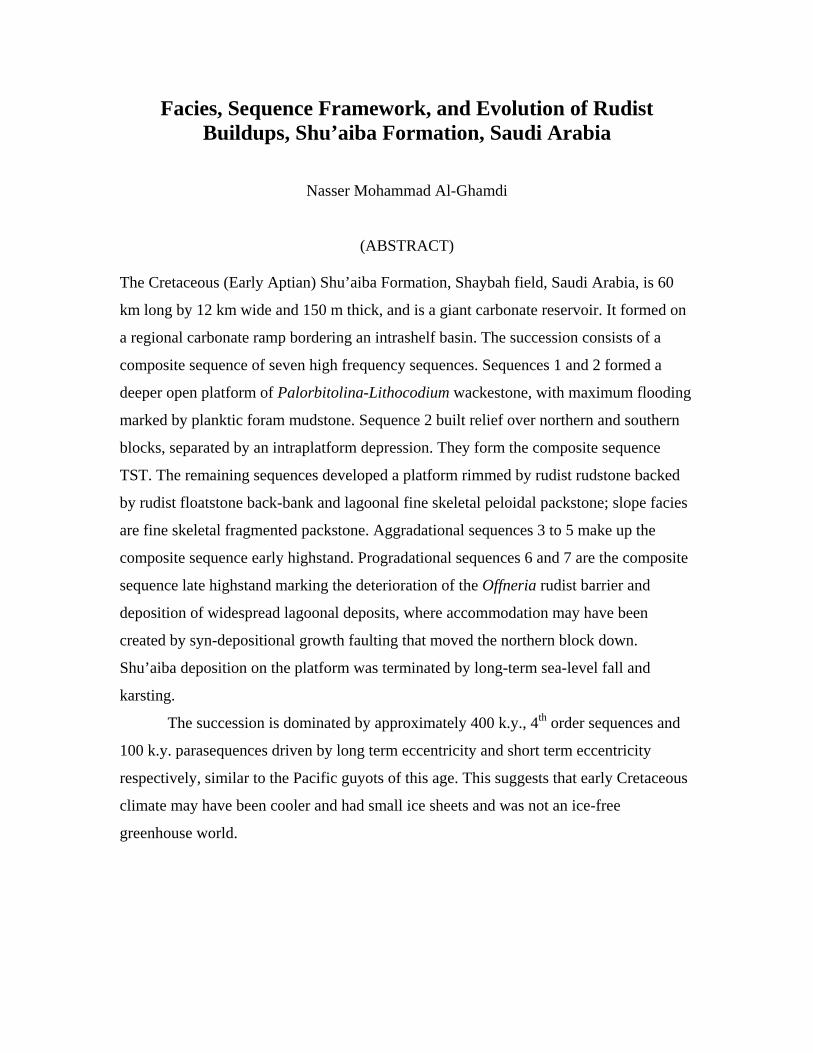
The Cretaceous (Early Aptian) Shu’aiba Formation, Shaybah field, Saudi Arabia, is 60
km long by 12 km wide and 150 m thick, and is a giant carbonate reservoir. It formed on
a regional carbonate ramp bordering an intrashelf basin. The succession consists of a
composite sequence of seven high frequency sequences. Sequences 1 and 2 formed a
deeper open platform of Palorbitolina-Lithocodium wackestone, with maximum flooding
marked by planktic foram mudstone. Sequence 2 built relief over northern and southern
blocks, separated by an intraplatform depression. They form the composite sequence
TST. The remaining sequences developed a platform rimmed by rudist rudstone backed
by rudist floatstone back-bank and lagoonal fine skeletal peloidal packstone; slope facies
are fine skeletal fragmented packstone. Aggradational sequences 3 to 5 make up the
composite sequence early highstand. Progradational sequences 6 and 7 are the composite
sequence late highstand marking the deterioration of the Offneria rudist barrier and
deposition of widespread lagoonal deposits, where accommodation may have been
created by syn-depositional growth faulting that moved the northern block down.
Shu’aiba deposition on the platform was terminated by long-term sea-level fall and
karsting.
The succession is dominated by approximately 400 k.y., 4th order sequences and
100 k.y. parasequences driven by long term eccentricity and short term eccentricity
respectively, similar to the Pacific guyots of this age. This suggests that early Cretaceous
climate may have been cooler and had small ice sheets and was not an ice-free
greenhouse world.

iii
Acknowledgements
I would like to thank Aramco management and the Career Development Division
for giving me this chance to pursue my Masters degree and for giving me the authority to
work on the giant Shu’aiba reservoir of Shaybah field.
I gratefully acknowledge my advisor, J.F Read for his steady provision and
guidance through out all stages of this project.
I thank my committee members Ken Eriksson and Rick Law for reviewing my
thesis and providing me critical comments and suggestions.
I thank all geologists in Aramco who helped me get the data and special thanks to
Aus Al-Tawil, Bob Lindsay, Duffy Russell, Gurhan Aktas, Kumbe Sadler and Wyn
Hughes for their great efforts and for valuable discussions that helped clarify the
stratigraphy of the Shu’aiba Formation. Special thanks to Rashid Al-Mannai from
Aramco Services Company in Houston for facilitating and providing support.
Special thank to my wife and kids for motivating and encouraging me through the
past two years.
iv
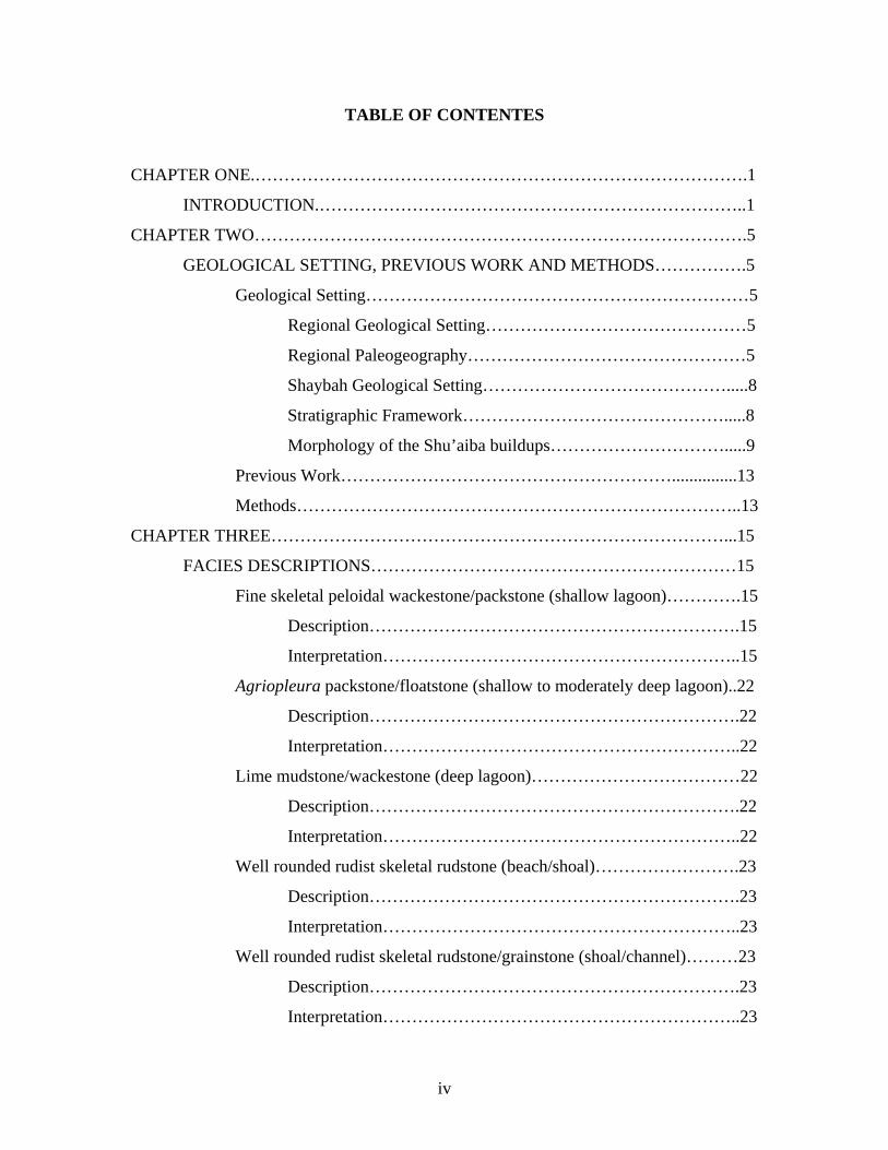
TABLE OF CONTENTES
CHAPTER ONE.………………………………………………………………………….1
INTRODUCTION.………………………………………………………………..1
CHAPTER TWO………………………………………………………………………….5
GEOLOGICAL SETTING, PREVIOUS WORK AND METHODS…………….5
Geological Setting…………………………………………………………5
Regional Geological Setting………………………………………5
Regional Paleogeography…………………………………………5
Shaybah Geological Setting…………………………………….....8
Stratigraphic Framework……………………………………….....8
Morphology of the Shu’aiba buildups………………………….....9
Previous Work…………………………………………………...............13
Methods…………………………………………………………………..13
CHAPTER THREE……………………………………………………………………...15
FACIES DESCRIPTIONS………………………………………………………15
Fine skeletal peloidal wackestone/packstone (shallow lagoon)………….15
Description……………………………………………………….15
Interpretation……………………………………………………..15
Agriopleura packstone/floatstone (shallow to moderately deep lagoon)..22
Description……………………………………………………….22
Interpretation……………………………………………………..22
Lime mudstone/wackestone (deep lagoon)………………………………22
Description……………………………………………………….22
Interpretation……………………………………………………..22
Well rounded rudist skeletal rudstone (beach/shoal)…………………….23
Description……………………………………………………….23
Interpretation……………………………………………………..23
Well rounded rudist skeletal rudstone/grainstone (shoal/channel)………23
Description……………………………………………………….23
Interpretation……………………………………………………..23
v
In situ caprinid floatstone/rudstone (rudist bank)………………………..23
Description……………………………………………………….23
Interpretation……………………………………………………..24
Caprinid skeletal-fragment floatstone/ (shoal to bank-crest)…………….24
Description……………………………………………………….24
Interpretation……………………………………………………..24
Rudist-fragment packstone/grainstone (shallow to deep fore-bank)…….24
Description……………………………………………………….24
Interpretation……………………………………………………..25
Caprotinid floatstone (shallow to deep back-bank)……………………...25
Description……………………………………………………….25
Interpretation…………………………………………………….25
Coral packstone/floatstone (open marine/lagoon)……………………….25
Description……………………………………………………….25
Interpretation……………………………………………………..25
Lithocodium-oncoid miliolid packstone (shallow marine platform)…….26
Description……………………………………………………….26
Interpretation……………………………………………………..26
Lithocodium wackestone/bindstone (open marine algal platform).……...26
Description……………………………………………………….26
Interpretation……………………………………………………..26
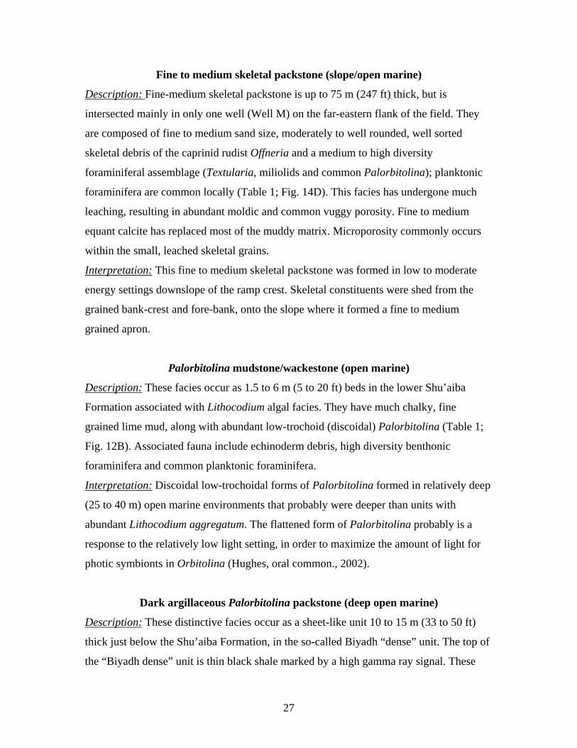
Fine to medium skeletal packstone (slope/open marine).………………..27
Description……………………………………………………….27
Interpretation……………………………………………………..27
Palorbitolina mudstone/wackestone (open marine)……………………..27
Description……………………………………………………….27
Interpretation……………………………………………………..27
Dark Argillaceous Palorbitolina packstone (deep open marine)………..27
Description……………………………………………………….27
Interpretation……………………………………………………..28
vi
Planktonic lime mudstone (deep open marine)…………………………..28
Description……………………………………………………….28
Interpretation……………………………………………………..28
Shaly lime mudstone/shale (intrashelf basin)……………………………29
Description……………………………………………………….29
Interpretation……………………………………………………..29
CHAPTER FOURE………………………………………………………………….......35
SEQUENCE STRATIGRAPHY………………………………………………...35
Sequence 1 (S1)………………………………………………………….36
Transgressive systems tract……………………………………....36
Maximum flooding surface and highstand systems tract………...36
Sequence 2 (S2)………………………………………………………….43
Transgressive systems tract……………………………………....43
Maximum flooding surface and highstand systems tract………...43
Sequence 3 (S3)………………………………………………………….44
Transgressive systems tract……………………………………....44
Maximum flooding surface and highstand systems tract………...44
Sequence 4 (S4)………………………………………………………….45
Transgressive systems tract……………………………………....45
Maximum flooding surface and highstand systems tract………...45
Sequence 5 (S5)………………………………………………………….46
Transgressive systems tract……………………………………....47
Maximum flooding surface and highstand systems tract………...46
Sequence 6 (S6)………………………………………………………….48
Transgressive systems tract……………………………………....47
Maximum flooding surface and highstand systems tract………...48
Sequence 7 (S7)………………………………………………………….48
Transgressive systems tract……………………………………....49
Maximum flooding surface and highstand systems tract………...49
CHAPTER FIVE………………………………………………………………………...53
DISCUSSIONS…………………………………………………………………..53
vii
Tectonics…………………………………………………………………53
Shu’aiba Hierarchy………………………………………………………54
Composite Sequence……………………………………………..54
Third versus Fourth Order Sequences……………………………56
Parasequences……………………………………………………58
Interpretation of Sequences………………………………………………58
Shu’aiba Composite Sequence…………………………………...58
Sequence 1 interpretation………………………………………...58
Sequence 2 interpretation.………………………………………..59
Sequence 3 interpretation.………………………………………..60
Sequence 4 interpretation.………………………………………..60
Sequence 5 interpretation.………………………………………..61
Sequence 6 interpretation.………………………………………..62
Sequence 7 interpretation.………………………………………..62
Paleoclimate and Eustasy………………………………………………...63
Greenhouse versus Transitional Climate………………………...63
Local Climate…………………………………………………….64
Eustatic Controls…………………………………………………65
CHAPTER SIX…………………………………………………………………………..68
SIGNIFICANCE…………………………………………………………………68
CHAPTER SEVEN……………………………………………………………………...71
CONCLUSIONS………………………………………………………………...71
REFERENCES…………………………………………………………………………..73

viii
LIST OF FIGURES
Fig. 1 Geological map for the Arabian Plate……………………………………………...2
Fig. 2 Base map for Shaybah field………………………………………………………..3
Fig. 3 Paleogeographic map for the Arabian Plate………….…………………………….4
Fig. 4A Global paleogeographic map during Early Cretaceous…………………………..6
Fig. 4B Model-predicted wind stress during Early Cretaceous…………………………...7
Fig. 5A Chronostratigraphic section for megasequence AP8……………………………10
Fig. 5B Chronostratigraphic diagram for the Shu’aiba Formation………………………11
Fig. 6 Carbon isotope correlation………………………………………………………..12
Fig. 7A Detailed N-S cross section………………………………………………………17
Fig. 7B Detailed E-W cross section……………………………………………………...18
Fig. 8A Simplified facies distribution of N-S cross section……………………………..19
Fig. 8B Simplified facies distributions of E-W cross section……………………………20
Fig. 9 Schematic depositional profile……………………………………………………21
Fig. 10 Core sample photographs of facies………………………………………………30
Fig. 11 Core sample photographs of facies………………………………………………31
Fig. 12 Core sample photographs of facies………………………………………………32
Fig. 13 Thin section photographs of facies………………………………………………33
Fig. 14 Thin section photographs of facies………………………………………………34
Fig. 15 Facies map (sequence 2)………………………………………………................38
Fig. 16 Facies map (sequence 3)………………………………………………................39
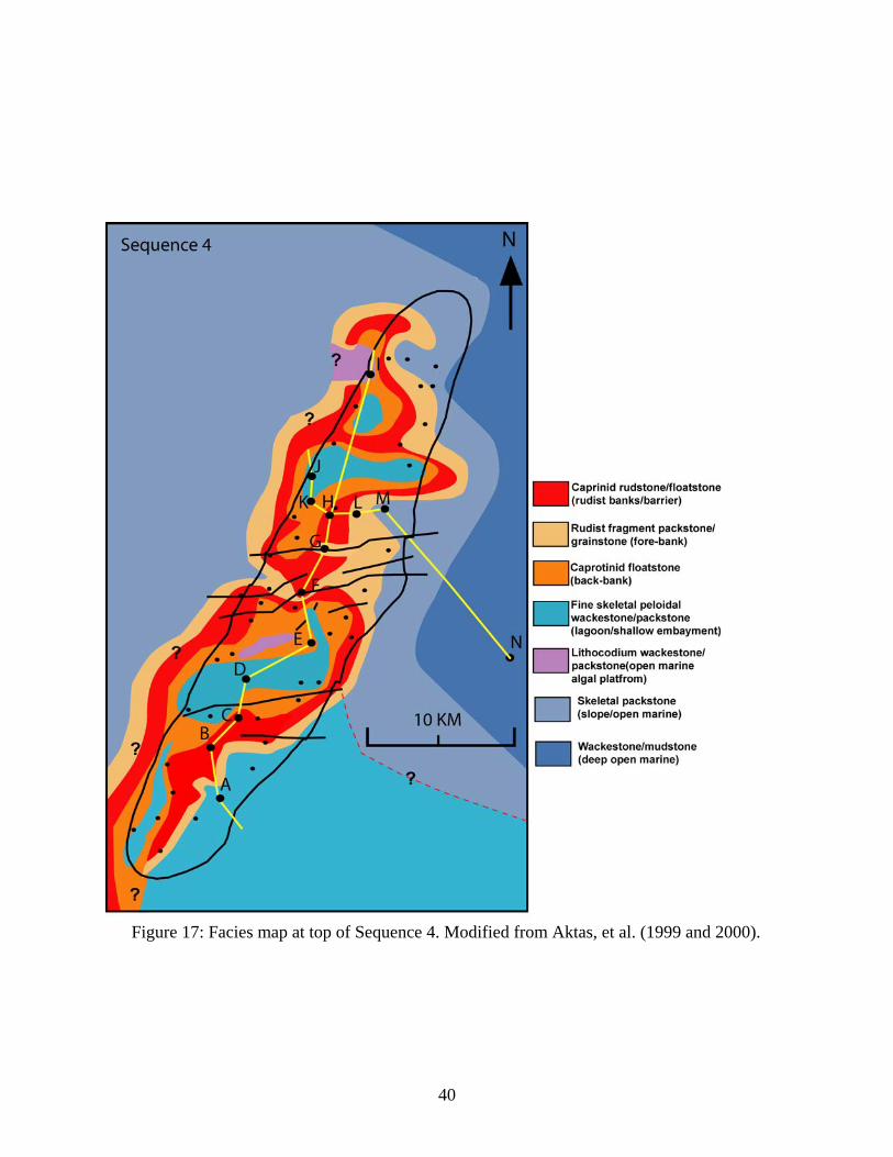
Fig. 17 Facies map (sequence 4)………………………………………………................40
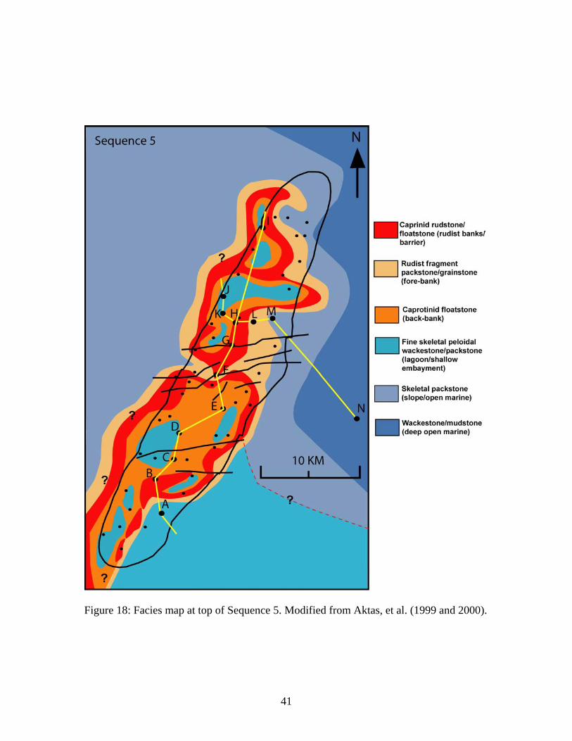
Fig. 18 Facies map (sequence 5)………………………………………………................41
ix
Fig. 19 Facies map (sequence 6)………………………………………………................42
Fig. 20 Core sample photographs of sequence boundaries………………………………51
Fig. 21 Core sample photographs of contact surfaces, karst and fractures………………52
Fig. 22 Reconstruction time-slice cross-sections………………………………………...55
Fig. 23 Early Cretaceous sea-level curves………………………….................................67

x
LIST OF TABLES
Table 1 Brief facies descriptions…………………………………………………………16
Table 2 Summary of sequences 1 to 7…………………………………………………...37
1
CHAPTER ONE
INTRODUCTION
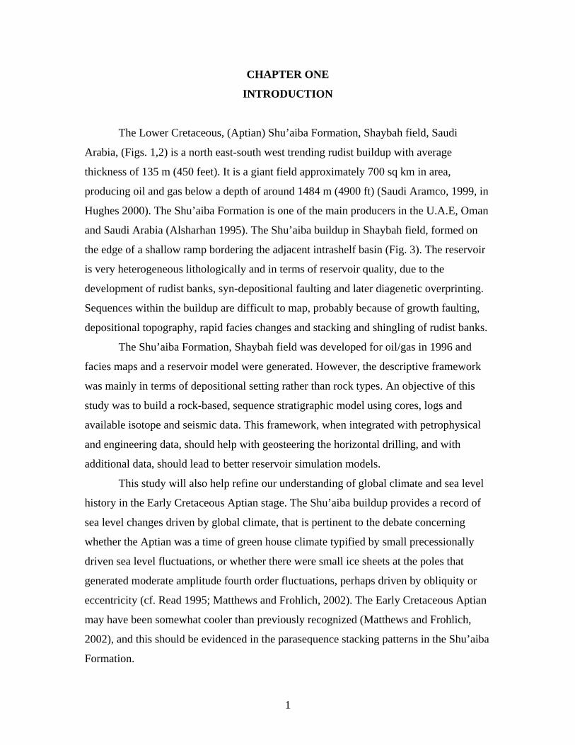
The Lower Cretaceous, (Aptian) Shu’aiba Formation, Shaybah field, Saudi
Arabia, (Figs. 1,2) is a north east-south west trending rudist buildup with average
thickness of 135 m (450 feet). It is a giant field approximately 700 sq km in area,
producing oil and gas below a depth of around 1484 m (4900 ft) (Saudi Aramco, 1999, in
Hughes 2000). The Shu’aiba Formation is one of the main producers in the U.A.E, Oman
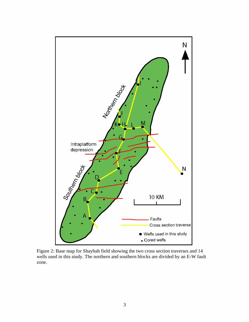
and Saudi Arabia (Alsharhan 1995). The Shu’aiba buildup in Shaybah field, formed on
the edge of a shallow ramp bordering the adjacent intrashelf basin (Fig. 3). The reservoir
is very heterogeneous lithologically and in terms of reservoir quality, due to the
development of rudist banks, syn-depositional faulting and later diagenetic overprinting.
Sequences within the buildup are difficult to map, probably because of growth faulting,
depositional topography, rapid facies changes and stacking and shingling of rudist banks.
The Shu’aiba Formation, Shaybah field was developed for oil/gas in 1996 and
facies maps and a reservoir model were generated. However, the descriptive framework
was mainly in terms of depositional setting rather than rock types. An objective of this
study was to build a rock-based, sequence stratigraphic model using cores, logs and
available isotope and seismic data. This framework, when integrated with petrophysical
and engineering data, should help with geosteering the horizontal drilling, and with
additional data, should lead to better reservoir simulation models.
This study will also help refine our understanding of global climate and sea level
history in the Early Cretaceous Aptian stage. The Shu’aiba buildup provides a record of
sea level changes driven by global climate, that is pertinent to the debate concerning
whether the Aptian was a time of green house climate typified by small precessionally
driven sea level fluctuations, or whether there were small ice sheets at the poles that
generated moderate amplitude fourth order fluctuations, perhaps driven by obliquity or
eccentricity (cf. Read 1995; Matthews and Frohlich, 2002). The Early Cretaceous Aptian
may have been somewhat cooler than previously recognized (Matthews and Frohlich,
2002), and this should be evidenced in the parasequence stacking patterns in the Shu’aiba
Formation.
2
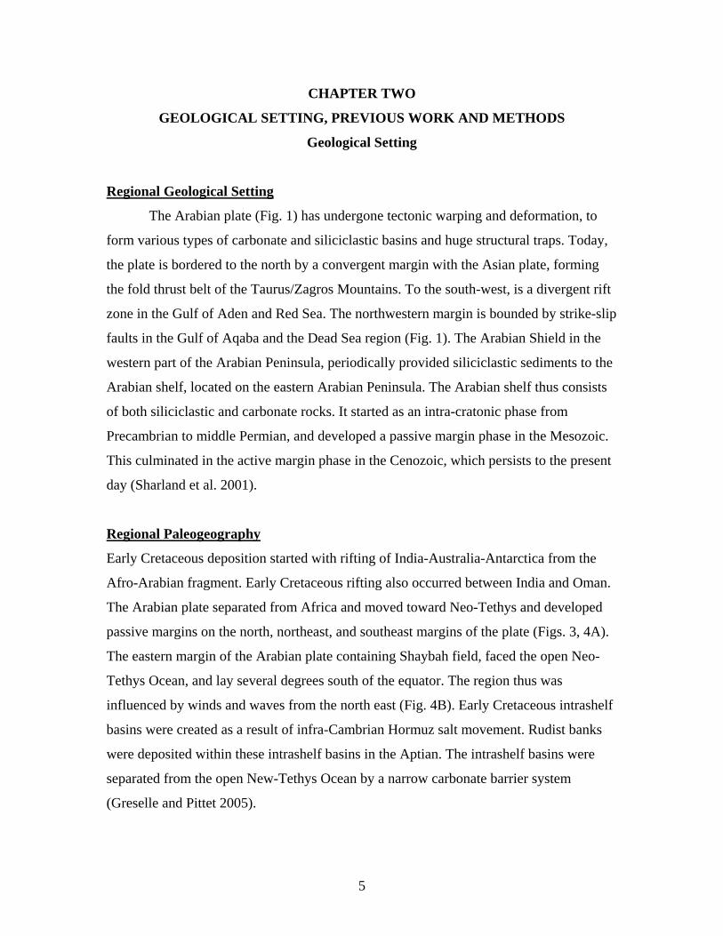
Figure 1: Geological map for the Arabian plate showing major structural elements and the location of Shaybah field. Modified from Sharland at el. (2001).
3
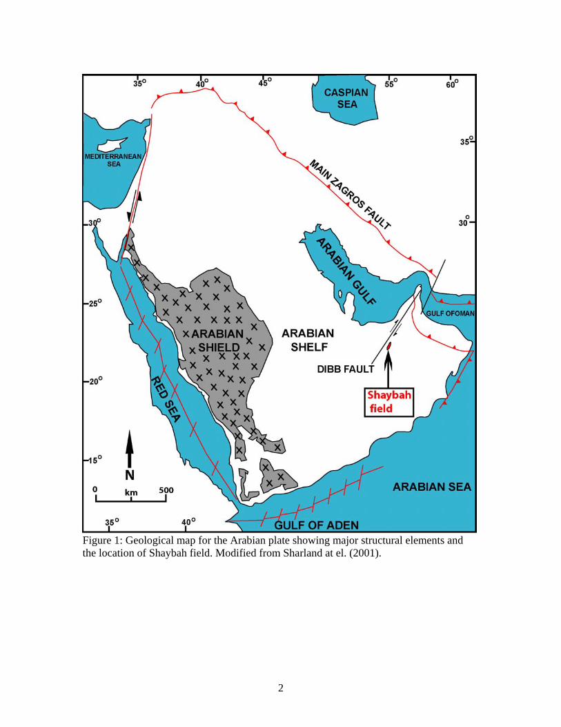
Figure 2: Base map for Shaybah field showing the two cross section traverses and 14 wells used in this study. The northern and southern blocks are divided by an E-W fault zone.
4
Figure 3: Paleogeographic map for the Arabian Plate in Aptian showing the location of Shaybah field and the intrashelf basins. Modern plate boundaries shown with red lines. Modified from Murris (1980) in Sharland et al. (2001).
5
CHAPTER TWO
GEOLOGICAL SETTING, PREVIOUS WORK AND METHODS
Geological Setting
Regional Geological Setting
The Arabian plate (Fig. 1) has undergone tectonic warping and deformation, to
form various types of carbonate and siliciclastic basins and huge structural traps. Today,
the plate is bordered to the north by a convergent margin with the Asian plate, forming
the fold thrust belt of the Taurus/Zagros Mountains. To the south-west, is a divergent rift
zone in the Gulf of Aden and Red Sea. The northwestern margin is bounded by strike-slip
faults in the Gulf of Aqaba and the Dead Sea region (Fig. 1). The Arabian Shield in the
western part of the Arabian Peninsula, periodically provided siliciclastic sediments to the
Arabian shelf, located on the eastern Arabian Peninsula. The Arabian shelf thus consists
of both siliciclastic and carbonate rocks. It started as an intra-cratonic phase from
Precambrian to middle Permian, and developed a passive margin phase in the Mesozoic.
This culminated in the active margin phase in the Cenozoic, which persists to the present
day (Sharland et al. 2001).
Regional Paleogeography
Early Cretaceous deposition started with rifting of India-Australia-Antarctica from the
Afro-Arabian fragment. Early Cretaceous rifting also occurred between India and Oman.
The Arabian plate separated from Africa and moved toward Neo-Tethys and developed
passive margins on the north, northeast, and southeast margins of the plate (Figs. 3, 4A).
The eastern margin of the Arabian plate containing Shaybah field, faced the open Neo-
Tethys Ocean, and lay several degrees south of the equator. The region thus was
influenced by winds and waves from the north east (Fig. 4B). Early Cretaceous intrashelf
basins were created as a result of infra-Cambrian Hormuz salt movement. Rudist banks
were deposited within these intrashelf basins in the Aptian. The intrashelf basins were
separated from the open New-Tethys Ocean by a narrow carbonate barrier system
(Greselle and Pittet 2005).

6
Figure 4A: Global paleogeographic map showing the position of Arabian plate during the Early Cretaceous (120 Ma). (Modified from Ron Blakey 2005). After Scotese et al. (1989).

7
Albian (June, July and August)
Figure 4B: Model-predicted wind stress during Early Cretaceous showing that eastern facing margins of Arabian Plate were windward margins. The star (*) is the location for Shaybah field (Modified from Poulsen et al. 1999).

8
Shaybah Geological Setting
The Shu’aiba Formation in Shaybah field is mainly Early Cretaceous, Lower
Aptian (Hughes, 2000 and 20005). Shaybah field is located on a north-south trending,
doubly plunging anticline, divided by a zone of east-west faults, into northern and
southern blocks (Fig. 1). The field is located on a basement uplift that appears to have
influenced the growth of the buildup, implying syn-sedimentary tectonics. The regional
structure was mainly affected by northeast-southwest trending faulting parallel to the
Dibba lineament, and sub-parallel to the trend of Shaybah field (Fig. 1). The present
Shaybah structure was developed during the Cenomanian in response to intra-oceanic
compressional tectonics in the Tethys region, and was truncated by pre-Aruma erosion
(Middle Turonian unconformity) related to uplift of ophiolitic nappes in Oman (Aktas
1998). Syn-depositional faulting influenced thickness and facies development of the
Shu’aiba buildup. Formation Micro-Imager (FMI) data indicate that faults and fractures
are more extensive than is evident in cores and on seismic data (Aktas 1998). The field
was divided into two depositional blocks by an east-northeast trending growth fault zone;
each block has distinctive facies and subtle differences in sequence stratigraphic
development.
Stratigraphic Framework
Sharland et al. (2001) divided the Arabian shelf succession into eleven
tectonostratigraphic megasequences resulting from major tectonic and global eustatic sea
level events. Megasequence AP8 which contains the Shu’aiba Formation, has a duration
of 57 m.y and extends from the Late Jurassic, early Tithonian unconformity to the
Cretaceous middle Turonian unconformity (Fig. 5A). Megasequence AP8 is composed of
three 2nd order sequences (Vail et al. 1977; Weber et al. 1995) each with a duration of
about 10 to 20 m.y each. Early Berriasian K10 is the maximum flooding surface for the
lower supersequence, early Aptian K70 is the maximum flooding surface for the middle
super sequence containing the Shu’aiba Formation, and late Albian K110 is the
maximum flooding surface for the upper supersequence.
The middle 2nd order super sequence of megasequence AP8 (Fig. 5A) is bounded
at the base by the Late Valanginian unconformity and is capped by the Late Aptian
9
unconformity. The Shuaiba Formation forms the upper part of this supersequence and
contains two major maximum flooding surfaces K70 (120 m.y.) and K80 (116 m.y.)
(Sharland et al. 2001).
The Shu’aiba carbonate, Shaybah field, overlies Barremian Biyadh reservoir are
dated as early Aptian, based on rudists, foraminifera and calcareous algae; deposition
probably extended into the late Aptian along the flanks of Shaybah field (Fig. 5B ;
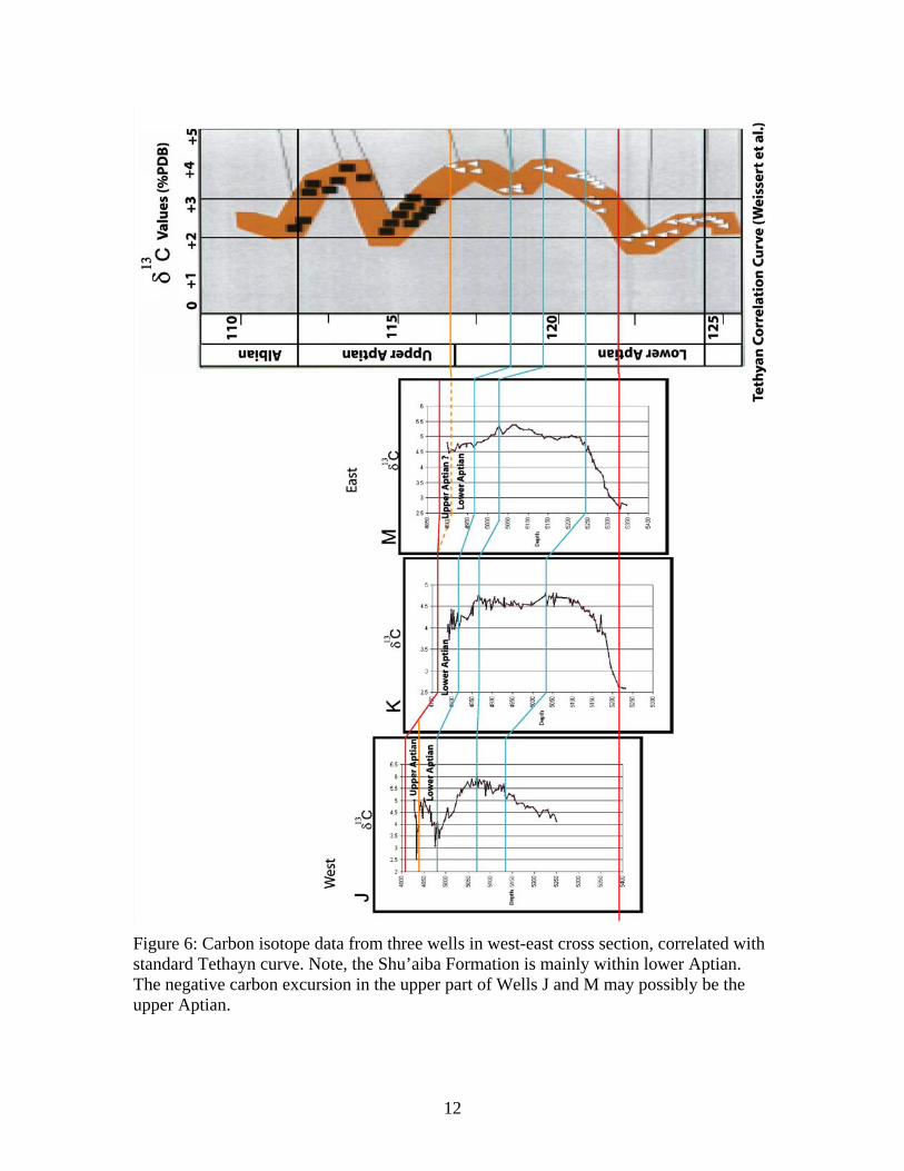
Hughes 2000). Carbon isotope dating of the succession was not definitive (Fig. 6).
However, there is a suggestion that the uppermost beds could be late Aptian on the basis
of the C-isotope curve, but this is controversial.
Sharland et al. (2001) considered that the Shu’aiba Formation formed a large
scale sequence extending from the upper Biyadh “dense” unit to the pre-Albian
unconformity. This large sequence contains two genetic stratigraphic sequences (GSS)
with the regional maximum flooding surfaces, K70 and K80 (Fig. 5A). Flooding surface
K70 was probably picked at the thin black shale at the upper part of Biyadh “dense”
(Sharland et al. 2001). Flooding surface K80 is not present in the Shu’aiba Formation in
Shaybah field, but is a sub-regional marker in the “tar unit” within the Bab Member,
Shu’aiba Formation, in the intrashelf basin in the U.A.E (Aldabal and Alsharhan, 1989,
Boichard et al. 1995; Azzam and Taher, 1995, in Sharland et al. 2001).
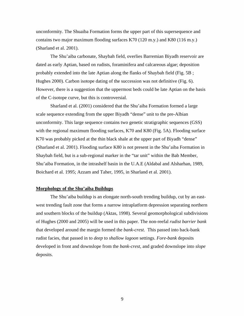
Morphology of the Shu’aiba Buildups
The Shu’aiba buildup is an elongate north-south trending buildup, cut by an east-
west trending fault zone that forms a narrow intraplatform depression separating northern
and southern blocks of the buildup (Aktas, 1998). Several geomorphological subdivisions
of Hughes (2000 and 2005) will be used in this paper. The non-reefal rudist barrier bank
that developed around the margin formed the bank-crest. This passed into back-bank
rudist facies, that passed in to deep to shallow lagoon settings. Fore-bank deposits
developed in front and downslope from the bank-crest, and graded downslope into slope
deposits.

10
Figure 5 A: Chronostratigraphic section for megasequence AP8 (149-92 Ma) shows three second order sequences, sensu Vail et al. (1977). The Shu’aiba Formation is within the second-order TST and HST of the middle sequence. Modified from Sharland et al. (2001).

11
Figure 5B: Chronostratigraphic diagram showing the ages and sequence stratigraphy for the Shu’aiba Formation in the U.A.E and Saudi Arabia.
12
Figure 6: Carbon isotope data from three wells in west-east cross section, correlated with standard Tethayn curve. Note, the Shu’aiba Formation is mainly within lower Aptian. The negative carbon excursion in the upper part of Wells J and M may possibly be the upper Aptian.
13
Previous Work
The Shu’aiba reservoir, Shaybah field, was discovered in 1968, but few wells
were drilled. Preliminary sedimentological and petrophysical work was done by Walthall
(1968), Bowsher (1971) and Husseini (1975). Sedimentological studies and facies
distribution maps were done by Ziegler (1976). More recently, Aktas et al. (1998, 1999
and 2000) produced stratigraphic framework and facies maps that were integrated into the
first geological model. Hughes (2000 and 2005) did an extensive study of the biota,
providing a biostratigraphic and paleo-ecological framework for the reservoir. These
studies also generated a broad sequence stratigraphic framework to better characterize the
reservoir. Aktas (1998) recognized two composite sequences, seven high frequency
sequences or reservoir zones, and 16 parasequences, based on the depositional setting and
stacking of the facies. Hughes (2000) divided the Shu’aiba Formation into the lower
Shu’aiba, middle Shu’aiba and upper Shu’aiba units based on depositional environments
and faunal constituents, each unit having a distinctive lithologic makeup and geometry.
The Shu’aiba Formation was studied extensively in U.A.E and Oman. Six third
order sequences were recognized, three on the platform, and three on the margin. Of the
upper three sequences, two prograde into the intrashelf basin, and the last one is the
siliciclastic-prone Bab member (Kerans 2004; Yose et al. 2006).
In Shaybah field, the upper Biyadh “dense” unit and the Shu’aiba Formation form
a composite sequence with a duration of about 3 to 4 m.y (Sharland et al. 2001; Haq and
Al-Qahtani 2005; Yose et al. 2006), where the base is the top of the Biyadh reservoir unit
and the top is the late Aptian unconformity capping the Shu’aiba Formation.
Methods
Fourteen cores through the Shu’aiba buildup, Shaybah field (Fig. 2) housed in the
Saudi Aramco core lab in Dhahran, Saudi Arabia and totaling 1490 m (4920 ft), were
logged and examined using a binocular microscope. The cores were selected based on the
core condition and location, to form two transects, one along the length of the buildup
and the other across the northern part of the buildup (Fig. 2). Core descriptions included
14
gross lithology (shale, limestone, and dolomite), rock type, grain-size, shape and sorting,
vertical succession of lithologies, location of bounding surfaces, types of biotic
constituents and porosity types. An extended Dunham classification (Dunham 1962;
Embry and Klovan 1971) was used for describing the carbonate rock types. Thin sections
were examined during the core logging to confirm the types of constituents, (including
forams) and any diagenetic modification of grains and matrix. Three cores were selected
for more detailed thin section study to better characterize the facies and pore types. The
computer drafted core descriptions were plotted along with gamma ray and porosity-
permeability logs for each well. Sequence boundaries, maximum flooding surfaces and
various scales of sequences and parasequences were picked on the logged sections.
Sequence boundaries were picked at significant erosional surfaces above successions of
parasequences that progressively shallowed and or / thinned up-section. Maximum
flooding surfaces were placed at the base of the deepest water facies within a sequence
and at the tops of upward deepening trends of parasequence sets, some of which showed
upward-thickening successions. Where possible, parasequence boundaries and maximum
flooding surfaces were traced across the buildups, to generate a layering model.
Seismic and isotope data were examined to constrain the sequence picks along the
margin of the buildup where clinoform development was likely. However, these proved
of limited value. Facies cross-sections within this sequence stratigraphic framework were
made by interpolating between cored wells using Walther’s law.
In order to correlate the sequences, the base of the Shu’aiba Formation was used
as a datum for the cross sections, because it has a distinctive high gamma ray response in
all wells associated with a thin stylolitic shale layer. The northern and southern blocks
were tied together using the top Shu’aiba unconformity, to bridge the medial fault zone.
However, this resulted in the unconformity on the northern block being lower than the
unconformity on the southern block, which may be an artifact of the datum used. It is not
meant to imply that the present structure look has this form.
Facies maps for several time slices were modified from Aktas et al. (1999 and
2000) using the well data from the present study. These maps help clarify regional facies
distribution, and provide geologic context for the detailed logged cores.
15
CHAPTER THREE
FACIES DESCRIPTIONS
Two major types of rudist were recognized in the Shu’aiba buildups. These are
Caprinid and Caprotinid rudists. Caprinid rudists are large recumbent type and occur in
bank-crest and fore-bank settings, that contain in situ Offneria or rudist debris. Caprotinid
rudists are elevator-type and commonly occur in deep back-bank (Glossomyophorus) or
in the shallow lagoon (Agriopleura) (Russell, 2001; Hughes, 2000 and 2005).
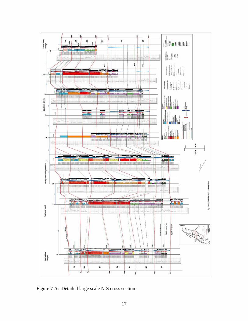
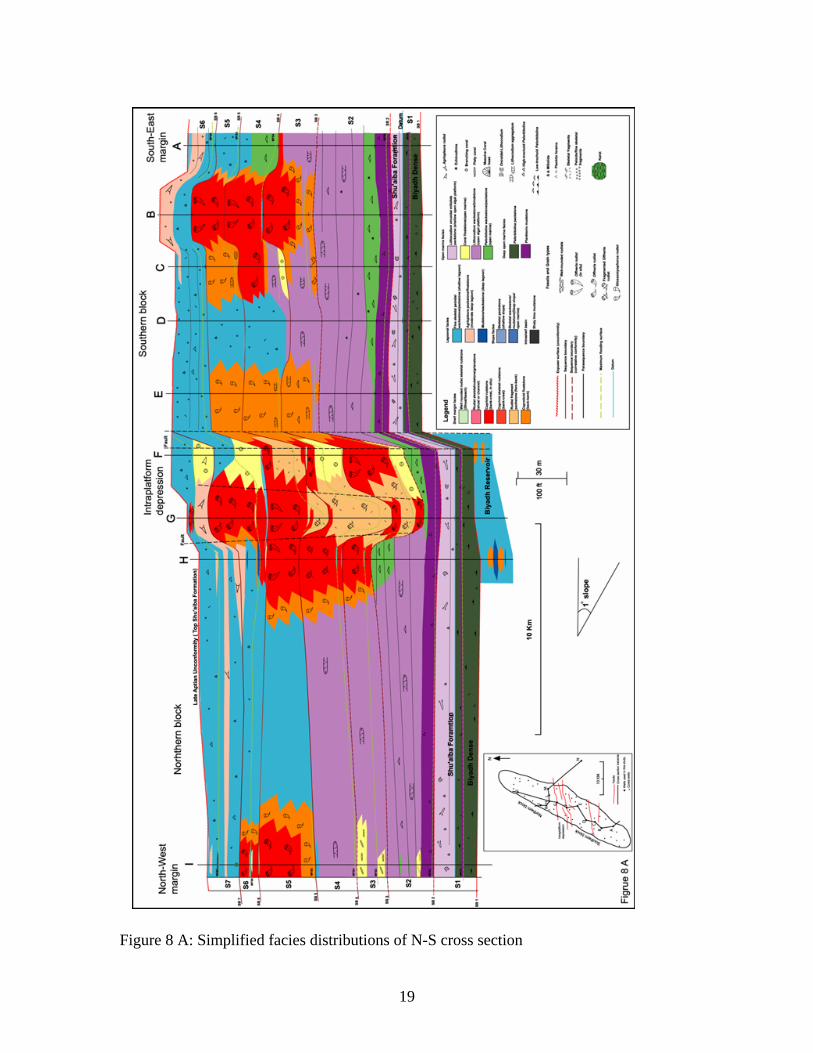
The facies are summarized in Table 1; their detailed distribution is shown on the
large scale, well-log cross-sections (Figs. 7A and B) and their simplified distribution are
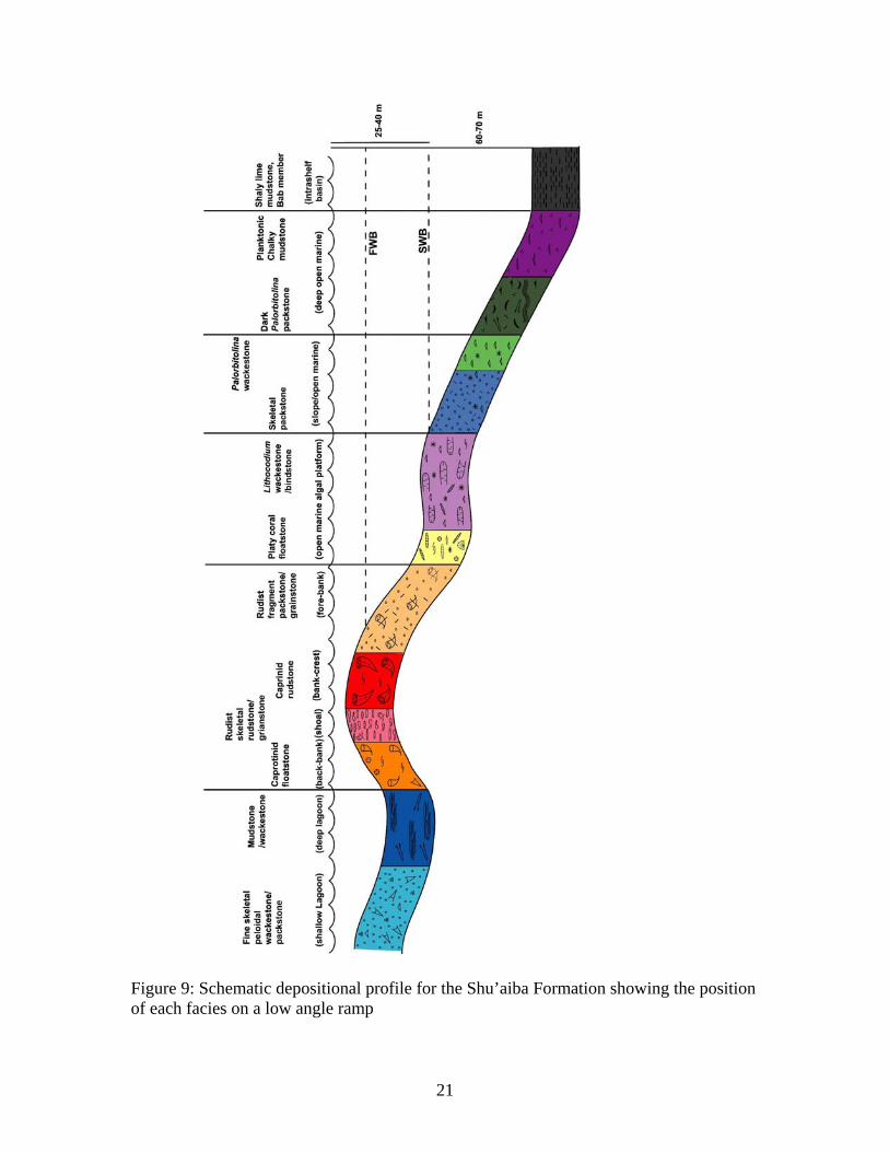
shown in Figures 8A and B. The depositional profile (Fig. 9) illustrates schematically the
idealized distribution of the facies. A brief description of the sediment types is given
below, arranged from shallow lagoon to deep open marine facies, along with interpreted
depositional environments, supplemented with information in Hughes (2000 and 2005)
and Aktas (1998). The facies are illustrated in Figures 10 to 14.
Fine skeletal peloidal wackestone/packstone (shallow lagoon)
Description: These wackestone, packstone and minor grainstone occur in the upper part
of Shu’aiba buildup interlayered with Agriopleura floatstone facies. They are massive to
low angle cross-bedded, composed of very fine to fine and rarely medium sand sized,
rounded and well to moderately sorted, skeletal peloidal grains along with variable
amount of mud (Table 1; Figs. 10A and 13A). They contain abundant and high diversity
assemblages of miliolids and benthonic foraminifera, common to rare high-trochoid
foram Palorbitolina, common dasyclad alga and rare codiacean alga Lithocodium.
Moldic and microporosity are common within skeletal grains resulting from complete or
partial dissolution. Fine equant calcite cements are common and occur within the
intergranular matrix.
Interpretation: These skeletal peloidal wackestone to packstone were formed in a shallow
lagoonal environment in water depth of 5 to 10 m. The fine grain size indicates low

16
17
Figure 7 A: Detailed large scale N-S cross section

18
Figure 7B: Detailed large scale E-W cross section
19
Figure 8 A: Simplified facies distributions of N-S cross section

20
Figure 8B: simplified facies distributions of E-W cross section
21
Figure 9: Schematic depositional profile for the Shu’aiba Formation showing the position of each facies on a low angle ramp
22
energy conditions with rare cross bedded grainstone forming during rare high energy
events or with shallowing.
Agriopleura packstone/floatstone (shallow to moderately deep lagoon)
Description: These Agriopleura packstone to floatstone form 3 to 8 m (10 to 25 ft) thick
units in the upper part of Shu’aiba buildup. They consist of large elongate fragments of
both Agriopleura blumenbachi (U-shaped) and Agriopleura marticensis (V-shaped)
rudists (Hughes. 2000 and 2003) (Table 1; Fig. 10B). The matrix between the rudists is a
skeletal peloidal mud-dominated packstone to grainstone of very fine to fine grained,
rounded, well sorted, skeletal fragments and variable amounts of lime mud, along with
abundant diverse of benthonic and miliolid foraminifera, common to rare high-trochoid
Palorbitolina and common dasyclad algae Salpingoporella dinarica . Fine to medium
equant calcite cements replaced the mud matrix and plug most of intergranular porosity.
Abundant moldic porosity is due to dissolution of the skeletal grains. Microporosity is
common within grains due to partial leaching. Vuggy porosity is rare.
Interpretation: These Agriopleura packstone to floatstone mainly formed in a shallow to
moderately deep lagoonal environment within the photic zone with depths of 10-20 m
(Hughes, 2000).
Lime mudstone/wackestone (deep lagoon)
Description: These facies were mainly penetrated in one well (Well J and possibly Well
A) where they form 15 to 30 m (50 to 100 ft) thick units. They are silty to very fine
mudstone to wackestone that are highly bioturbated, with argillaceous wispy
microstylolitic seams and nodular bedding. They consist of diverse foraminifera
(miliolids, textularids, Vercorsella, Debarina hahounerensis, Orbitolina), rare planktonic
foraminifera and rare to common Lithocodium, and Dasyclad algae Salpingoporella
dinarica (Fig. 13B). Chert within these facies forms thin layers from 0.3 to 1.5 m thick
(Table 1. Figs. 10C).
Interpretation: This facies formed in low energy, deep lagoonal environments indicated
by abundant fine carbonate, diverse foraminifera assemblages, along with rare planktonic
23
forams. Chert in the Shu’aiba Formation (Well J) may be related to the dissolution of
sponge spicules (cf. Russell, 2001).
Well rounded rudist skeletal rudstone (beach/shoal)
Description: This facies forms thin massive units 0.6 – 1.5 m (2 to 5 ft) thick at the base
of sequences 5, 6 and 7 (Wells F, H, I and L), above rudist buildup facies. It consists of
gray to dark gray, well rounded, well sorted, very coarse sand-gravel-sized fragmented
and less common whole caprinid rudists dominated by Offneria. It is well cemented and
pyritized and generally has low porosity and permeability (Table 1; Fig. 10D).
Interpretation: These rudstones were deposited in high energy beach environments and
are the shallowest water facies developed, probably having formed in water depth less
than 5 m where recumbent rudists were transported from the subjacent shelf margin
buildup to the nearly beach.
Well rounded rudist skeletal rudstone/grainstone (shoal/channel)
Description: These grainstone and rudstone units are up to 60 m (200 ft) thick, in Well K
on the north western side of the field. They consist of cross-bedded, coarse sand-granule-
size, very well rounded, well-sorted, fragments of rudists including (Offneria) with or no
mud matrix (Table 1; Figs. 10 E and 13 C). Calcite cements are common to rare and there
is much intergranular porosity.
Interpretation: These skeletal rudstone-grainstone formed in very shallow, very high
energy, current-swept environments within the shoal complex. Offneria rudists were
transported from the bank-crest toward the back-bank sand shoal and into channels where
currents winnowed fine carbonate.
In situ caprinid floatstone/rudstone (rudist bank)
Description: These facies form non-cyclic units 15 to 30 m (50 to 100 ft) thick in the
middle of the Shu’aiba Formation, commonly beneath well rounded rudist rudstone. They
are caprinid-rudist rudstone to floatstone composed of poorly sorted, very large (several
centimeters), whole recumbent rudists, dominantly Offneria murgensis (Table 1; Fig.
10F). Skeletal packstone to wackestone matrix occurs between rudists, and lime matrix

24
commonly partially fills intraskeletal voids (Fig. 13D). Large equant blocky cements are
common near the top of these units. Some late cements plug matrix porosity, with
remaining porosity being intercrystalline.
Interpretation: Caprinid floatstone to rudstone formed on the moderate energy portion of
the bank-crest in less than 5 m of water. Abundant large and unbroken rudists were
formed in place; however, the moderate energy setting allowed trapping of fine mud
matrix and infiltration of mud into intraskeletal voids. Given the spacing of the rudists, it
is unlikely that they could have formed a sufficiently effective baffle to trap mud under
high energy conditions.
Caprinid skeletal-fragment floatstone/rudstone (shoal to bank-crest)
Description: These facies form a unit 5 to 25 m (16 to 80 ft) thick in the middle of the
buildup, commonly below the bank-crest facies. They are skeletal rudstone to floatstone
composed of coarse sand-granule-size, poor to medium sorted, reworked skeletal debris
dominantly of the caprinid rudist Offneria, less common Glossomyophorus costatus and
bivalves (Table 1; Fig. 11A). The matrix generally is skeletal grainstone to packstone and
less common wackestone and mudstone. Porosity includes abundant vuggy and moldic
types (Fig. 13E). Microporosity is common to rare and occurs within rudists. Very fine
dolomite crystals within rudists have been observed in one well (Well I).
Interpretation: These caprinid skeletal fragment floatstone/rudstone generally formed on
crests of high energy rudist buildups in water depths of 5-10 m, extending onto the
proximal fore bank and back-bank.
Rudist-fragment packstone/grainstone (shallow to deep fore-bank)
Description: These facies form thick units interbedded with caprinid rudstone, mainly
along the western side of the field (Well L) and in the intraplatform depression (Well G).
They are mainly skeletal packstone to grainstone, (and rare wackestone) and are
composed of fine-coarse sand size, angular to moderately rounded, moderately sorted,
skeletal debris of the rudists Offneria and less common Glassomyophorus along with
bivalves, corals, echinoderms and Lithocodium debris (Table 1; Figs. 11B and 13F). Fine
25
to coarse equant calcite cements are common and remaining porosity includes common
moldic, intergranular and microporosity.
Interpretation: These facies formed in shallow to relatively deep fore-bank settings by
accumulation of skeletal sands sand from bank crest Offneria rudists. Glassomyophorus
and Lithocodium debris may have been transported through inter-bank channels from the
deep back-bank or lagoon (Hughes, 2000).
Caprotinid floatstone (shallow to deep back-bank)
Description: This caprotinid floatstone occurs below the caprinid rudstone in units of 3 to
15 m (10 to 50 ft) thick. This facies is also distinctive in the upper most part of the
Biyadh reservoir just below the Biyadh “dense” unit. It consists of coarse-sand to pebble-
size, poorly sorted, whole, elevator-type Glossomyophorus costatus and less common
Agriopleura along with skeletal bivalve debris, corals and echinoderm debris (Table 1;
Fig. 11C). Lithocodium aggregatum, Palorbitolina and benthonic foraminifera also occur
in this facies toward the western side of the field (e.g. Well E). The wackestone/mud-rich
packstone matrix contains rare coarse blocky calcite cements. Porosity includes common
moldic, microporosity and rare vugs.
Interpretation: Caprotinid rudists were deposited in a shallow to moderately deep (15 to
30 m) back-bank setting with low to moderate energy indicated by abundant mud matrix.
Coral packstone/ floatstone (open marine/ lagoon)
Description: Coral floatstone occurs in the Lower Shu’aiba Formation as 5 m (17 ft)
thick units that have both platy and branching corals within the Lithocodium algal
platform unit. Branching coral-rich units also occur in the upper Shu’aiba Formation (e.g.
Well F) (Fig. 14B). Platy corals usually form floatstone, and branching corals form
muddy packstone or floatstone with wackestone-mudstone matrix; associated fauna
includes Lithocodium aggregatum, bivalves, echinoderm debris and Palorbitolina (Table
1; Fig. 11 E). The corals are coarse sand-gravel size, platy to rounded, poorly to
moderately sorted; there are some massive coral heads locally (Fig.11 F).
Interpretation: Branching coral facies formed in water depths of 15 to 25 m, shallower
than coral-free Lithocodium facies, in relatively low energy lagoonal settings favoring

26
accumulation of muddy matrix of packstone and floatstone. The platy coral facies formed
in slightly deeper waters along flanks of the buildups (20 to 40 m).
Lithocodium-oncoid miliolid packstone (shallow marine platform)
Description: This facies occurs at the base of the Shu’aiba buildup resting on the Biyadh
Formation with a sharp contact. It forms a regional 4 to 6 m (13 to 19 ft) blanket-like
layer in most wells. It consists of intensely bioturbated wackestone and packstone with
large irregular burrows, and fine to medium sand-size, poorly sorted peloids, pebble-size
Lithocodium lumps or oncoids and lime mud (Table 1; Figs. 11D and 14A). It also has
abundant sand-size miliolids and Textularia, but commonly lacks Palorbitolina. Moldic
and microporosity are common (Table 1).
Interpretation: Lithocodium miliolid packstone was deposited on the shallow carbonate
platform in water depths less than 15 m, under moderate energy (Aktas, 1998). This is a
shallower facies than the deeper platform Lithocodium aggregatum wackestone.
Lithocodium wackestone/bindstone (open marine algal platform)
Description: These facies form units up to 45 m (149 ft) thick in the lower part of
Shu’aiba Formation, directly above deep planktonic mudstone facies. These Lithocodium
facies have wispy irregular laminations and common burrows, and are muddy carbonates
(mainly wackestone, with lesser mudstone, floatstone and bindstone). They contain
common to abundant encrusting nodular to sheet-like Lithocodium aggregatum, and fine
to medium sand-size, poorly sorted, bivalve and echinoderm debris in a chalky lime mud
matrix (Table 1; Figs. 12A; 14C). Associated fauna includes some platy corals,
fragments of Glossomyophorus, diverse benthonic foraminifera (including some
miliolids) and rare to common planktonic foraminifera.
Interpretation: These muddy Lithocodium facies were deposited in the photic zone above
storm wave base, on a moderate to relatively deep (20 to 35 m) open marine platform,
under low to moderate energy conditions, indicated by abundant mud and open marine
biota. They also formed in deep marine lagoonal environments behind rudist banks
(Hughes, 2000).
27
Fine to medium skeletal packstone (slope/open marine)
Description: Fine-medium skeletal packstone is up to 75 m (247 ft) thick, but is
intersected mainly in only one well (Well M) on the far-eastern flank of the field. They
are composed of fine to medium sand size, moderately to well rounded, well sorted
skeletal debris of the caprinid rudist Offneria and a medium to high diversity
foraminiferal assemblage (Textularia, miliolids and common Palorbitolina); planktonic
foraminifera are common locally (Table 1; Fig. 14D). This facies has undergone much
leaching, resulting in abundant moldic and common vuggy porosity. Fine to medium
equant calcite has replaced most of the muddy matrix. Microporosity commonly occurs
within the small, leached skeletal grains.
Interpretation: This fine to medium skeletal packstone was formed in low to moderate
energy settings downslope of the ramp crest. Skeletal constituents were shed from the
grained bank-crest and fore-bank, onto the slope where it formed a fine to medium
grained apron.
Palorbitolina mudstone/wackestone (open marine)
Description: These facies occur as 1.5 to 6 m (5 to 20 ft) beds in the lower Shu’aiba
Formation associated with Lithocodium algal facies. They have much chalky, fine
grained lime mud, along with abundant low-trochoid (discoidal) Palorbitolina (Table 1;
Fig. 12B). Associated fauna include echinoderm debris, high diversity benthonic
foraminifera and common planktonic foraminifera.
Interpretation: Discoidal low-trochoidal forms of Palorbitolina formed in relatively deep
(25 to 40 m) open marine environments that probably were deeper than units with
abundant Lithocodium aggregatum. The flattened form of Palorbitolina probably is a
response to the relatively low light setting, in order to maximize the amount of light for
photic symbionts in Orbitolina (Hughes, oral common., 2002).
Dark argillaceous Palorbitolina packstone (deep open marine)
Description: These distinctive facies occur as a sheet-like unit 10 to 15 m (33 to 50 ft)
thick just below the Shu’aiba Formation, in the so-called Biyadh “dense” unit. The top of
the “Biyadh dense” unit is thin black shale marked by a high gamma ray signal. These
28
argillaceous Palorbitolina packstone/wackestone are dark gray, impure carbonates with
hard grounds, normal-graded scour fills, wispy clayey lamination with abundant
microstylolites and organic rich seams. They are composed of granule size, low-
trochoidal Palorbitolina, fine-to-medium sand-size, poorly sorted peloids, along with
common miliolid, textularids, planktonic foraminifera, common debris of bivalves and
echinoderms, and common glauconite and pyrite in an argillaceous, organic-rich lime
mud matrix (Table 1; Figs. 12C and 14E).
Interpretation: These argillaceous Palorbitolina packstone facies formed in a deep, open
marine, low energy platform environment in 40 to 50 m water depth, as indicated by the
open marine forams, glauconite and organic matter. Very low sedimentation rates, and
reduced oxygen levels are suggested by the hardgrounds, high organic content, dark
color, common glauconite and terrigenous clay minerals (Tucker and Wright 1990). The
abundant low-trochoidal Orbitolina indicate relatively deep water, low light settings, in
part related to turbidity due to suspended terrigenous mud. Abundant fine lime mud and
clay probably accumulated under prevailing low energy conditions, with some storm
reworking indicated by scour fills.
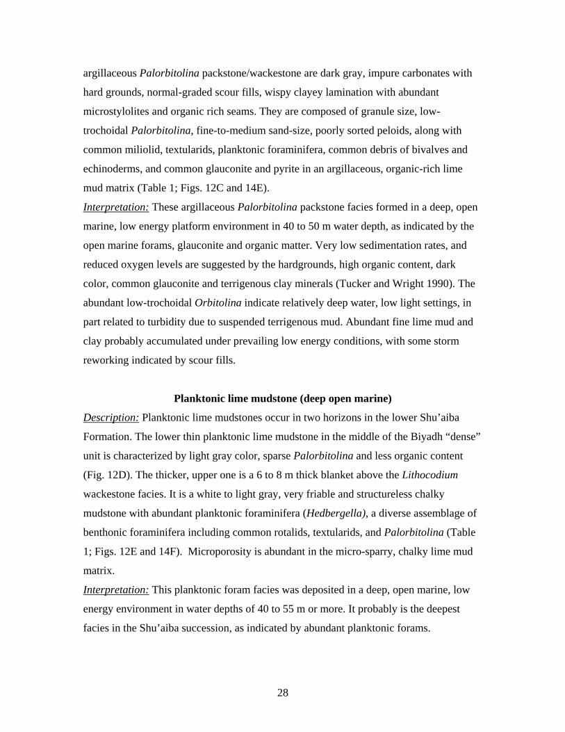
Planktonic lime mudstone (deep open marine)
Description: Planktonic lime mudstones occur in two horizons in the lower Shu’aiba
Formation. The lower thin planktonic lime mudstone in the middle of the Biyadh “dense”
unit is characterized by light gray color, sparse Palorbitolina and less organic content
(Fig. 12D). The thicker, upper one is a 6 to 8 m thick blanket above the Lithocodium
wackestone facies. It is a white to light gray, very friable and structureless chalky
mudstone with abundant planktonic foraminifera (Hedbergella), a diverse assemblage of
benthonic foraminifera including common rotalids, textularids, and Palorbitolina (Table
1; Figs. 12E and 14F). Microporosity is abundant in the micro-sparry, chalky lime mud
matrix.
Interpretation: This planktonic foram facies was deposited in a deep, open marine, low
energy environment in water depths of 40 to 55 m or more. It probably is the deepest
facies in the Shu’aiba succession, as indicated by abundant planktonic forams.
29
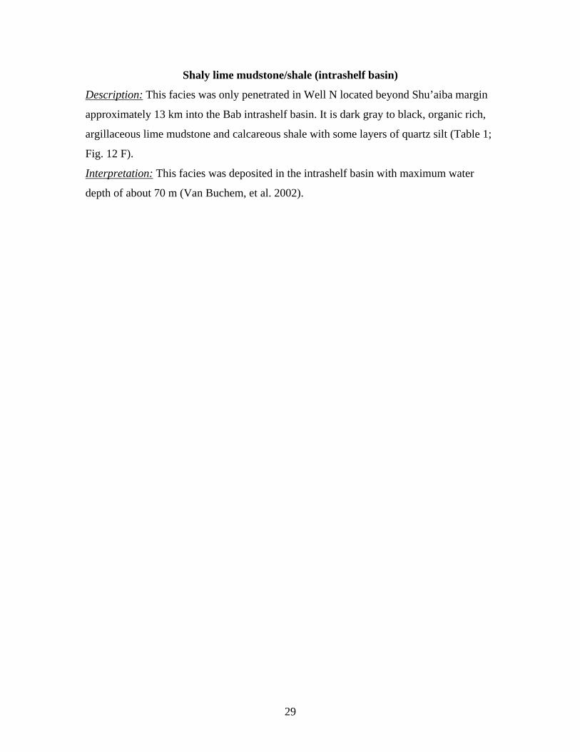
Shaly lime mudstone/shale (intrashelf basin)
Description: This facies was only penetrated in Well N located beyond Shu’aiba margin
approximately 13 km into the Bab intrashelf basin. It is dark gray to black, organic rich,
argillaceous lime mudstone and calcareous shale with some layers of quartz silt (Table 1;
Fig. 12 F).
Interpretation: This facies was deposited in the intrashelf basin with maximum water
depth of about 70 m (Van Buchem, et al. 2002).

30
Figure 10: Core sample photographs of typical facies. (A) Fine skeletal peloidal packstone (shallow lagoon). (B) Agriopleura floatstone in fine skeletal packstone matrix. (C) Lime mudstone with chert (deep lagoon) (D) Well rounded rudist (mainly Offneria) well- cemented rudstone (shoal/beach). (E) Rounded rudist skeletal grainstone/rudstone (shoal/channel). (F) In situ caprinid floatstone of Offneria (bank-crest).
A B
C D
E F
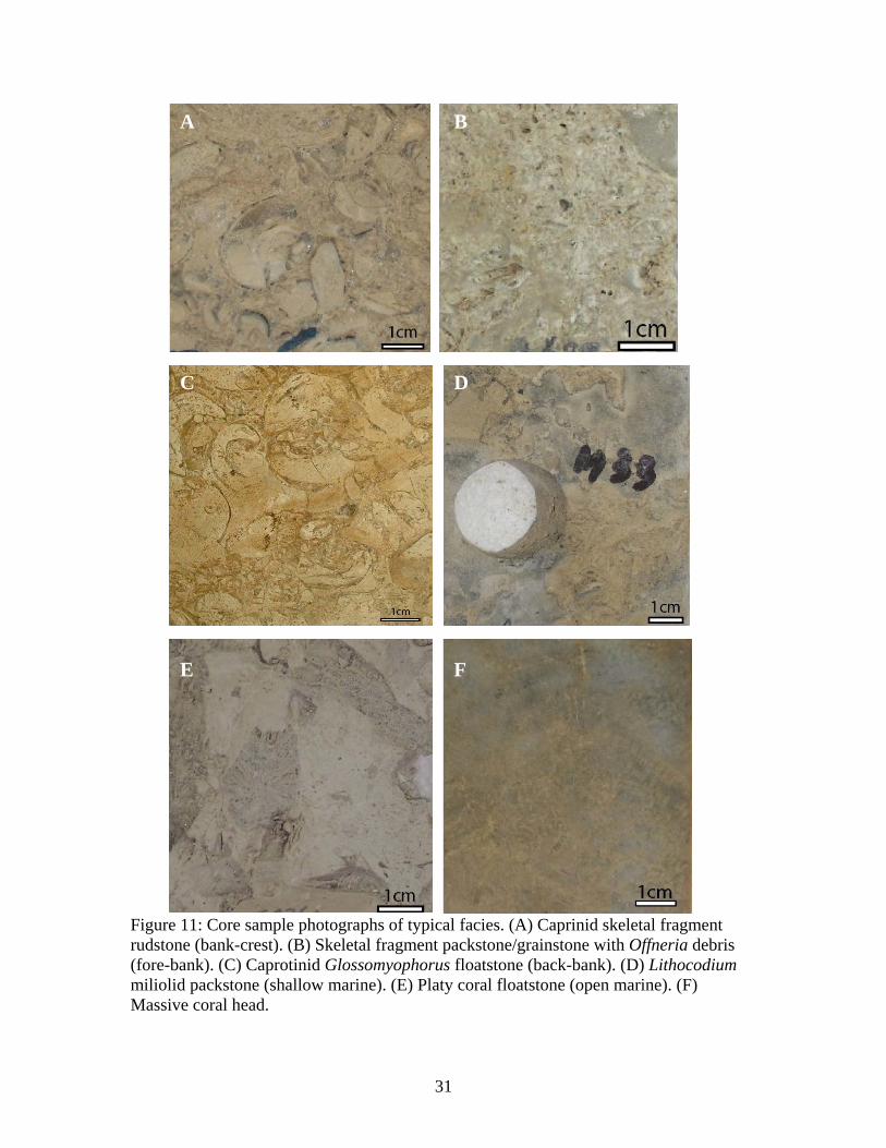
31
Figure 11: Core sample photographs of typical facies. (A) Caprinid skeletal fragment rudstone (bank-crest). (B) Skeletal fragment packstone/grainstone with Offneria debris (fore-bank). (C) Caprotinid Glossomyophorus floatstone (back-bank). (D) Lithocodium miliolid packstone (shallow marine). (E) Platy coral floatstone (open marine). (F) Massive coral head.
A B
E F
C D

32
Figure 12: Core sample photographs of typical facies. (A) Lithocodium aggregatum wackestone (open marine algal platform). (B) Palorbitolina wackestone (open marine). (C) Dark gray Palorbitolina packstone of Biyadh “dense” unit. (D) Light gray mudstone (MFS1). (E) Planktic chalky mudstone (MFS 2). (F) Shaly lime mudstone, Bab member (intrashelf basin).
D
E F
33
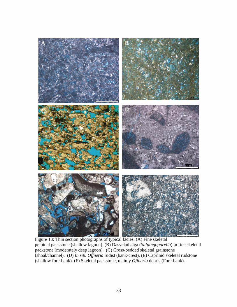
Figure 13: Thin section photographs of typical facies. (A) Fine skeletal peloidal packstone (shallow lagoon). (B) Dasyclad alga (Salpingoporella) in fine skeletal packstone (moderately deep lagoon). (C) Cross-bedded skeletal grainstone (shoal/channel). (D) In situ Offneria rudist (bank-crest). (E) Caprinid skeletal rudstone (shallow fore-bank). (F) Skeletal packstone, mainly Offneria debris (Fore-bank).
A
E F
B
DC
B
D

34
Figure 14: Thin section photographs of typical facies. (A) Lithocodium miliolid packstone (shallow marine, basal Shu’aiba Formation). (B) Branching coral packstone within lagoonal environments (Well F). (C)Lithocodium aggregatum wackestone. (D) Fine skeletal packstone (slope). (E) Dark argillaceous Palorbitolina packstone (Biyadh “dense”). (F) Planktic chalky mudstone (deep open marine).
A B
C D
E F

35
CHAPTER FOUR
SEQUENCE STRATIGRAPHY
The facies, sequences and bounding surfaces are shown in the detailed well log
cross-sections (Figs. 7A and B) and the simplified facies- and sequence framework are
also shown in Figures 8A and B. Map views of facies distributions generated at tops of
sequences 2, 3, 4, 5 and 6 by modifying previous facies maps of Aktas et al. (1999, 2000)
and are shown in figures 15 to 19.
Sequences, defined as relatively conformable successions of genetically related
strata bounded at their bases and tops by unconformities or their correlative conformities
(Vail et al. 1977), were defined using the criteria of Sarg (1987), Kerans and Tinker
(1997) and Handford and Loucks (1993). In this study, sequence boundaries
characterized by local to regional exposure locally with shale infill into karstic vugs, are
common at the top of the Shu’aiba formation, but local breccia or well-rounded rudist
rudstone do occur locally at tops of other sequences high in the succession. However,
most sequence boundaries within the Shu’aiba Formation lack such evidence of exposure,
and sequence boundaries were placed at tops of shallowing-upward successions, beneath
deepening upward units. Correlative conformities in deeper, open-marine settings were
placed directly beneath the shallowest water facies in the deeper, water succession,
marking a major lowering of relative sea level. Maximum flooding surfaces were placed
beneath the deepest water unit in a sequence. Boundaries of parasequences in the
succession were defined using flooding surfaces at the tops of upward shallowing
successions. Up to 30 parasequences were noted, but only fifteen to seventeen
parasequences were mapped in several wells. Only a few parasequences are traceable
throughout the buildup, as in the lower Shu’aiba Formation.
Gamma ray logs were used to trace sequence boundaries, high frequency
sequences and some of the parasequences, except in the middle Shu’aiba Formation with
its numerous rudist buildups. The-gamma ray logs were difficult to use as a correlation
tool, because of the uniformly low values. Carbon isotope data from Aktas et al. (1998)
were used to constrain correlations for some wells on the west-east cross-section, and to
36
pick the lower to upper Aptian boundary along the western and eastern flank of the field
beneath the upper Aptian Bab member (Fig. 4).
Reflection seismic profiles were of limited use in defining internal geometry and
correlating units, because of the low quality data, presence of artifacts and lack of clear
definition of the top of the Shu’aiba Formation on the well-to-seismic ties. Near-surface
structures and large sand dunes on the surface may have influenced data acquisition
making it hard to process and interpret the data (Triebwasser, 1998).
Because of the controversy over the hierarchy of sequences in the Shu’aiba
Formation and equivalent units of the Arabian Plate, sequences labeled S1 to S 7 were
picked on the basis of facies stacking and bounding surfaces, with no implications as to
order or duration. Sequences are briefly summarized in Table 2, and are described below.
Sequence 1 (S1)
Sequence one rests on white, fine skeletal peloidal packstone (lagoonal facies) of
the Biyadh reservoir. This facies shallows up to small rudist mounds of the elevator-type
rudists Glossomyophorus and Agriopleura, similar to the facies in the upper part of the
Shu’aiba Formation; it may be a shallowing event of the large sequence beneath the
Shu’aiba composite sequence. Sequence one is a blanket-like unit with almost constant
thickness of about 18 to 24 m (60 to 80 ft). Its basal sequence boundary is the sharp
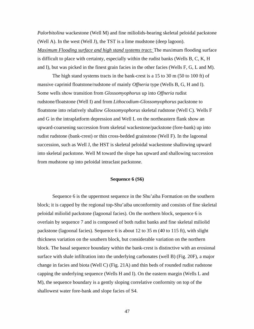
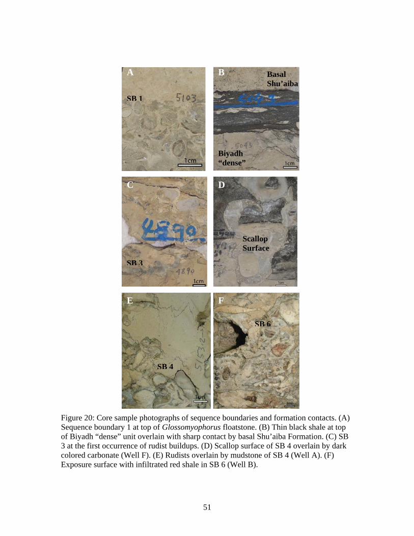
contact on the upper Biyadh reservoir (Fig. 20A), which is overlain by dark colored,
Palorbitolina-bearing carbonates of the Biyadh “dense” unit.
Transgressive systems tract: The transgressive systems tract is in the lower part of the
Biyadh dense unit and is about 6 to 10 m (20 to 30 ft) thick. It consists of two or more
parasequences of dark, argillaceous Palorbitolina packstone (open platform) containing
glauconite, pyrite and deep open marine biota (planktic forams, textularids). The
parasequences consists of wackestone overlain by low-trochoid Palorbitolina packstone
and may be capped by hardgrounds and scour surfaces. Two to three gamma ray spikes
marking clay, pyrite or glauconite form regional markers.
Maximum flooding surface and highstand systems tract: The maximum flooding surface
is placed below a thin 1.5 to 2 m (4 to 6 ft) light gray wackestone-mudstone with only

37
38
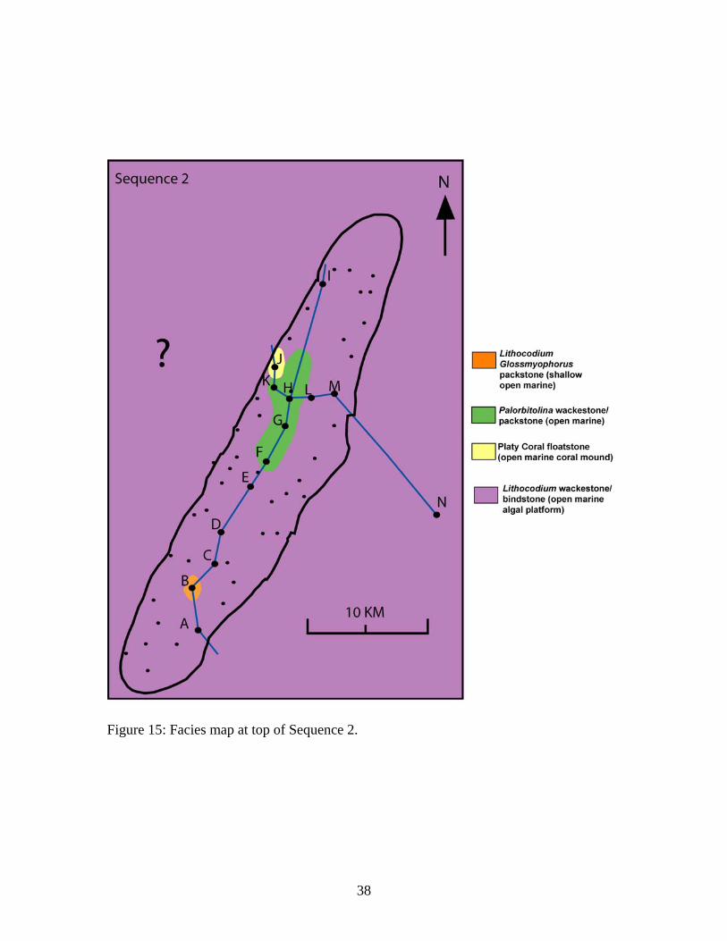
Figure 15: Facies map at top of Sequence 2.
39
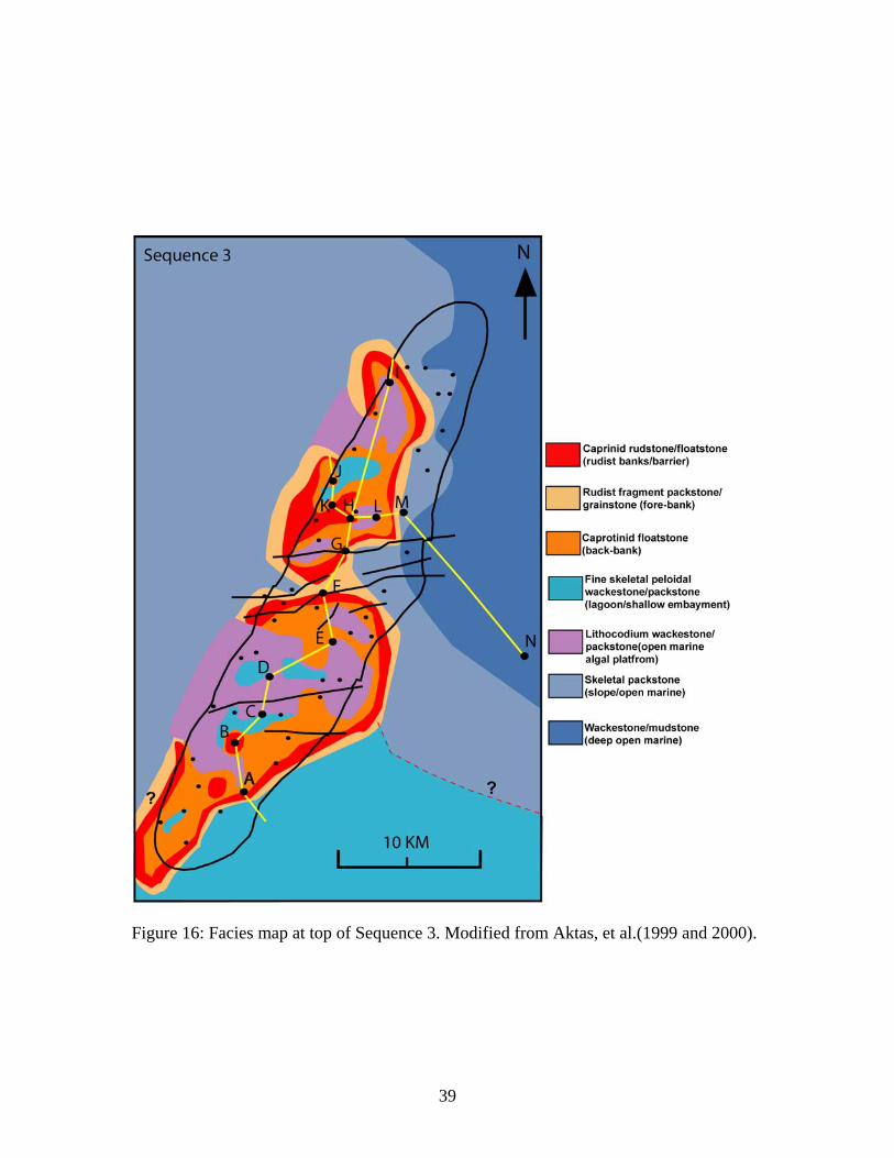
Figure 16: Facies map at top of Sequence 3. Modified from Aktas, et al.(1999 and 2000).
40
Figure 17: Facies map at top of Sequence 4. Modified from Aktas, et al. (1999 and 2000).
41
Figure 18: Facies map at top of Sequence 5. Modified from Aktas, et al. (1999 and 2000).

42
Figure 19: Facies map at top of Sequence 6. Modified from Aktas, et al. (1999 and 2000).
43
sparse Palorbitolina, relatively low shale content and low gamma ray response (Fig.
12D).
The high stand systems tract is 12 to 15 m (39 to 49 ft) thick, consisting of an
overall upward shallowing succession consisting of several parasequences, which show
an upward transition from dark, poorly fossiliferous mudstone to wackestone up into
Palorbitolina packstone, and then into oncoidal Lithocodium miliolid packstone. Several
gamma ray markers occur in the HST, as well as in the TST. The upper one is the
regional marker used to initially datum the sections, and is a thin (less than 0.3 m),
stylolitic black shale (Fig. 20B); the lower gamma ray markers are from several dark
shaly limestone horizons above and below the maximum flooding surface.
Sequence 2 (S2)
Sequence 2 is in the lower Shu’aiba Formation. In the southern block, this
sequence has layer-cake geometry with average thickness of 40 m (130 ft), but in the
northern block it is 10 to 38 m (32 to 124 ft) thick. On the west-east cross section (the
northern block), this sequence thins from 53 m (176 ft) in the west to 15 m (50 ft) in the
east in the intrashelf basin. The sequence 2 boundary is the correlative conformity at the
abrupt change in facies from oncoidal Lithocodium miliolid packstone facies (shallow
marine) of S1, above which is an upward deepening succession.
Transgressive systems tract: The transgressive systems tract is a very thin, locally
developed unit of Lithocodium or Palorbitolina wackestone that deepens up into a
planktic chalky mudstone.
Maximum flooding surface and highstand systems tract: The maximum flooding surface
(Fig. 12E) was placed near the base of the sheet-like, 7 m (23 ft) thick, white, planktic
chalky mudstone characterized by very low gamma ray response.
The high stand systems tract is up to 24 m (80 ft) thick, thinning toward the
eastern flank and into the fault zone (Wells F and G). It consists of up to 5 parasequences
in its thickest mounded development (Wells A, B, C, D, E and H). The parasequences
contain successively shallower facies up-section, from chalky mudstone that shallows up
into Palorbitolina mudstone/wackestone, into Lithocodium mudstone-wackestone and

44
local platy coral floatstone, especially on the northern block. Palorbitolina
wackestone/packstone is common on the central portion of the mound on the northern
block (Wells H and K). Thinned areas have few parasequences, reduced sections of
Lithocodium and to a lesser extent, Palorbitolina wackestone. The parasequences appear
to backstep toward the thickened mound crest.
Sequence 3 (S3)
Sequence 3 occurs in middle Shu’aiba Formation and contains the lowest rudist
facies. Sequence 3 ranges from 18 to 30 m (60 to 110 ft) thick in the southern and central
area, thinning onto the northern block and toward the flanks. On the platform, the basal
sequence boundary of S3 was placed at the sharp contact between Lithocodium
wackestone and the overlying rudist bearing limestones (Fig. 20C). On the eastern and
western ramp flanks, the sequence boundary is a correlative conformity between
Lithocodium wackestone and the overlying coral floatstone.
Transgressive systems tract: The transgressive systems tract commonly is a thin, less
than 3 m (10 ft), upward-fining unit of caprotinid floatstone (common Glossomyophorus
and rare Agriopleura). On the margin, platy coral floatstone may include thin lowstand to
transgressive deposits (Well L).
Maximum flooding surface and highstand systems tract: The maximum flooding surface
is placed beneath Lithocodium wackestone, but the MFS is difficult to pick in the rudist
buildups, as in Wells F, G and K on the northern block. Thin (0.3 m) Palorbitolina
wackestone or skeletal packstone horizons locally mark the MFS, such as in Wells K and
H.
The high stand systems tract is an upward-shallowing up succession, 12 to 21 m
(40 to 70 ft) thick. Wells within the platform interior show an upward-shallowing
succession of Lithocodium packstone/wackestone up into lagoonal skeletal peloidal
packstone/wackestone (Well D) or thin, caprotinid floatstone in the back-bank position
(Well C). Wells that penetrate the rudist rudstone typically show little facies succession
in the highstand (Wells H, F), whereas others (Well B) show an upward shallowing
succession of thin Lithocodium wackestone/mudstone up into caprotinid floatstone and
45
caprinid rudstone (Offneria rudists). On the flanks, the HST consists of Lithocodium
wackestone-bindstone capped by platy coral floatstone. In the intraplatform depression
(Well G), the high-stand is an upward shallowing unit of rudist-fragment
packstone/grainstone capped by caprinid skeletal fragment rudstone.
Sequence 4 (S4)
Sequence 4 in the middle Shu’aiba Formation has a thickness from 20 to 30 m (65
to 100 ft). The basal sequence boundary is locally a scalloped surface (Wells A and F)
(Figs. 20D and E) and commonly is a sharp contact showing an abrupt upward change in
facies. This sequence boundary can be regionally mapped across the field except on the
slope (Well M).
Transgressive systems tract: The transgressive systems tract where recognizable, is a 0 to
7 m (0 to 25 ft) thick upward-fining unit that deepens upward. It consists of a complex
mosaic of facies which differ from well to well. In sections dominated by rudist facies,
overlying rudist buildups of sequence 3, the sequence 4 TST commonly is not clearly
defined.
Maximum Flooding surface highstand systems tract: The maximum flooding surface in
sequence 4 is best recognized toward the eastern and western flanks of the field, where it
underlies open marine and slope facies. It was placed within deeper water, argillaceous
Palorbitolina mudstone in southeastern flank Well A, and at the base of lime mudstone
facies (deep lagoon) in the northwestern Well J. Within the rudist buildups, possible
maximum flooding surfaces might underlie thin layers of Palorbitolina skeletal
packstone low in the buildups (Wells H and K) or may occur at the turnaround between
upward-fining up into upward coarsening units (Well F).
The high stand systems tract of sequence 4 is a thick 12 m to 18 m (40 to 60 ft)
unit. Wells through the sequence 4 highstand bank-crest include Wells B, C, F and H, and
in which the rudist facies tend to be stacked on the sequence 3 rudist buildups. Some
bank-crest units show more in-place rudists up-section (Wells B and C); Well F shows a
transition from branching corals up into rudist rudstone, while Well H has rudist rudstone
up into rudist-skeletal fragment grainstone/rudstone. Sequence 4 lagoonal HST units are

46
the most open marine facies of sequences 3 to 7. They include deep-lagoon, burrowed
mudstone/wackestone (Well J) or Lithocodium wackestone/mudstone (Wells E and I) or,
especially in upper parts, shallow lagoonal, fine skeletal peloidal packstone/wackestone
(Well D). Flank wells in the north have Lithocodium wackestone and bindstone, and platy
coral facies, capped by rudist fragment packstone (Well L) grading downslope into
skeletal packstone (Well M). Thirty meters of fore-bank rudist fragment
wackestone/packstone/grainstone capped by thin rudist rudstone crest facies dominate
sections between the northern and southern blocks (Well G). In the south-east, the slope
section contains Palorbitolina wackestone/packstone up into peloid-skeletal
wackestone/packstone (Well A).
Sequence 5 (S 5)
Sequence 5 is relatively conformable on S4 in most wells, but evidence of a
sequence boundary is evident in several wells (Wells C, F and G). Sequence 5 is 15 to 20
m (49 to 65 ft) thick. The basal boundary of sequence 5 is relatively subtle within the
rudist margin (Wells B and H), being placed on the shallowest water facies within the
underlying rudist buildups of sequence 4, which include rudist-fragment rudstone (Well
H), in situ caprinid rudstone (Wells B and C) or local, thin units of rounded rudist
rudstone (Well F). Toward the northwest (Well I), the sequence boundary is a correlative
conformity between Lithocodium open marine facies of S4 and the overlying rudist bank.
It is difficult to pick in the eastern margin slope (Wells L and M), so it was placed on the
shallowest water slope facies of sequence 4.
Transgressive systems tract: The transgressive systems tract is difficult to recognize in
rudist-dominated sections (e.g. Wells B, H, K and I). In Well C, the TST is less than 3 m
(10 ft) of skeletal packstone and Glossomyophorus-Lithocodium packstone, and in Well
F, the TST is 6 to 9 m (20 to 30 ft) of caprinid rudstone deepening upward into skeletal
peloidal packstone and wackestone (fore-bank). In wells G and L, the TST is 15 to 20 m
(50 to 70 ft) of skeletal detrital packstone/wackestone (fore-bank). On the eastern slope,
the TST is an 8 m (28 ft) thick unit of skeletal packstone deepening upward to thin
47
Palorbitolina wackestone (Well M) and fine miliolids-bearing skeletal peloidal packstone
(Well A). In the west (Well J), the TST is a lime mudstone (deep lagoon).
Maximum Flooding surface and high stand systems tract: The maximum flooding surface
is difficult to place with certainty, especially within the rudist banks (Wells B, C, K, H
and I), but was picked in the finest grain facies in the other facies (Wells F, G, L and M).
The high stand systems tracts in the bank-crest is a 15 to 30 m (50 to 100 ft) of
massive caprinid floatstone/rudstone of mainly Offneria type (Wells B, G, H and I).
Some wells show transition from Glossomyophorus up into Offneria rudist
rudstone/floatstone (Well I) and from Lithocodium-Glossomyophorus packstone to
floatstone into relatively shallow Glossomyophorus skeletal rudstone (Well C). Wells F
and G in the intraplatform depression and Well L on the northeastern flank show an
upward-coarsening succession from skeletal wackestone/packstone (fore-bank) up into
rudist rudstone (bank-crest) or thin cross-bedded grainstone (Well F). In the lagoonal
succession, such as Well J, the HST is skeletal peloidal wackestone shallowing upward
into skeletal packstone. Well M toward the slope has upward and shallowing succession
from mudstone up into peloidal intraclast packstone.
Sequence 6 (S6)
Sequence 6 is the uppermost sequence in the Shu’aiba Formation on the southern
block; it is capped by the regional top-Shu’aiba unconformity and consists of fine skeletal
peloidal miliolid packstone (lagoonal facies). On the northern block, sequence 6 is
overlain by sequence 7 and is composed of both rudist banks and fine skeletal miliolid
packstone (lagoonal facies). Sequence 6 is about 12 to 35 m (40 to 115 ft), with slight
thickness variation on the southern block, but considerable variation on the northern
block. The basal sequence boundary within the bank-crest is distinctive with an erosional
surface with shale infiltration into the underlying carbonates (well B) (Fig. 20F), a major
change in facies and biota (Well C) (Fig. 21A) and thin beds of rounded rudist rudstone
capping the underlying sequence (Wells H and I). On the eastern margin (Wells L and
M), the sequence boundary is a gently sloping correlative conformity on top of the
shallowest water fore-bank and slope facies of S4.
48
Transgressive systems tract: The transgressive systems tract in the rudist banks is a 0 to 9
m (0 to 30 ft) thick unit of rudist skeletal rudstone (small rudist banks) (Wells G, H, I).
Well F has 15 m (50 ft) thick unit of branching coral packstone deepening up into high-
trochoid Palorbitolina packstone/wackestone (lagoonal facies). Wells A, B, C and J have
0.6 to 2.5 m (4 to 8 ft) of skeletal peloidal packstone (lagoonal facies). On the slope, the
TST is a thin unit of skeletal wackestone (Well M).
Maximum Flooding surface and high stand systems tract: The maximum flooding surface
on the bank-crest lies beneath a thin skeletal packstone within the rudist buildup in Wells
G and L, or beneath a thin mudstone or skeletal wackestone (shallow to deep lagoon) that
overlies rudist skeletal rudstone in Wells H and I. Within the lagoonal successions (Wells
A, B and C), the MFS is placed beneath the change in facies from skeletal packstone to
wackestone associated with a low gamma ray signal (e.g well A, B and C). In well F, in
the intraplatform depression, the MFS was placed at the base of major flooding unit of
high trochoid-Palorbitolina packstone/wackestone. Along the margin (Wells A and M),
the sequence 6 MFS appears to be at the base or within fine skeletal peloidal
packstone/wackestone, that resemble lagoonal facies.
Rudist banks are only patchily developed in the sequence 6 highstand. The high
stand systems tract is a 21 to 26 m (70 to 85 ft) thick, massive unit of caprinid rudstone
(Well G and L) that locally shallow up into rounded rudist rudstone (Well L). On the
northwestern flank, (Well I), there are small rudist banks with interbedded skeletal
packstone. In the east, within the shallow lagoonal successions, the HST is a 10 m (35 ft)
fine skeletal wackestone to packstone (shallow to moderately deep lagoon), that coarsen
up into Agriopleura packstone and floatstone into mudstone (Wells A, B, C, H and J)
locally with a fine packstone cap. Well F in the intraplatform depression has high-
trochoid Palorbitolina packstone/wackestone, coral packstone, fine skeletal peloidal
wackestone/packstone up to thin bed of cross-bedded grainstone. On the ramp slope
(Well M), fine skeletal detrital packstone slope facies shallow upward into medium-
coarse sand-sized skeletal packstone fore-bank facies.
Sequence 7 (S7)
49
Sequence 7 is present only on the northern block and ranges from 9 to 18 m (60 to
30 ft). The basal sequence boundary is the sharp contact at the top of the rudist bank-crest
of sequence 6 (Wells G and I) or the top of well-rounded rudist rudstone in Well L.
Within the platform, the basal sequence boundary was placed on sequence 6 Agriopleura
packstone facies (Wells H and J). On the slope (Well M) the correlative conformity is
placed on top of skeletal packstone fore-bank facies.
Transgressive system tract: The transgressive systems tract, where recognizable, is 3 to 7
m (10 to 25 ft) thick Agriopleura floatstone to packstone (Well G) or Agriopleura
packstone interbedded with skeletal mudstone/wackestone/packstone (Well H). Well L
has a well rounded rudist rudstone that deepens upward into rudist skeletal floatstone
interbedded with fine skeletal packstone.
Maximum flooding surface and high stand systems tract: The maximum flooding surface
is beneath a thin layer of mudstone (deep lagoon) in Well G and L, with planktic
foraminifera in Well G (Hughes, 1999). In Wells F, J and H, the MFS was placed beneath
the finest grained facies within the shallow lagoonal succession. On the flanks, the MFS
was placed at the base of the sequence, associated within a thin mudstone in Well I, that
has common planktic foraminifera downslope in Well M (Hughes, 1999). A second
flooding unit occurs higher in sequence 7 (Wells J and L). This flooding surface is a thin
layer of lime mudstone (deep lagoonal facies).
The high stand systems tract of sequence 7 is 4 to 7 m (15 to 25 ft) thick and
composed of two upward shallowing cycles. The lower one is fine skeletal peloidal
packstone that shallows up to Agriopleura floatstone (Wells H, I and J). The upper cycle
is fine skeletal packstone deepening up into mudstone (lagoonal facies) and shallowing
upward into fine packstone interbedded with Agriopleura floatstone. Well G has 3 m (10
ft) of Offneria rudist bank, just a few feet beneath the top Shu’aiba unconformity,
marking the last occurrence of the buildup in the study area. Well M in the eastern flank
has fine skeletal wackestone/packstone of Offneria debris and some Agriopleura fore-
bank facies (Hughes, 1999). In the upper most part of this sequence, shale from the Nahr-
Umr Formation is infiltrated into the upper Shu’aiba carbonate (Fig. 21B). This shale was
recognized in most wells. In wells L and I, karstic cavities (2 m; 7 ft) have penetrated

50
about 9 m (30 ft) deep into the upper Shu’aiba Formation. These karstic infills are mixed
green shale with fragments of carbonate rock (Fig. 20C).
51
Figure 20: Core sample photographs of sequence boundaries and formation contacts. (A) Sequence boundary 1 at top of Glossomyophorus floatstone. (B) Thin black shale at top of Biyadh “dense” unit overlain with sharp contact by basal Shu’aiba Formation. (C) SB 3 at the first occurrence of rudist buildups. (D) Scallop surface of SB 4 overlain by dark colored carbonate (Well F). (E) Rudists overlain by mudstone of SB 4 (Well A). (F) Exposure surface with infiltrated red shale in SB 6 (Well B).
A
SB 1
C
SB 3
D
Scallop Surface
E
SB 4
B
Biyadh “dense”
Basal Shu’aiba
F
SB 6

52
Figure 21: Core sample photographs showing; (A) Rudist overlain by sharp contact of SB6 and fine skeletal packstone (Well C). (B) Thin green shale infill coming from infiltration of Nahr-Umr shale into the upper part of Shu’aiba Formation. (C) Karst fill of mixed green shale and carbonate fragments (Well I). (D) Slickensides in lime mudstone (Well I). (E) Fractures filled with pyrite (Well F). (F) Core trays showing unconformable contact between Shu’aiba carbonate and green shale of Nahr-Umr Formation.
B
D
E
C
F
A
SB 6
53
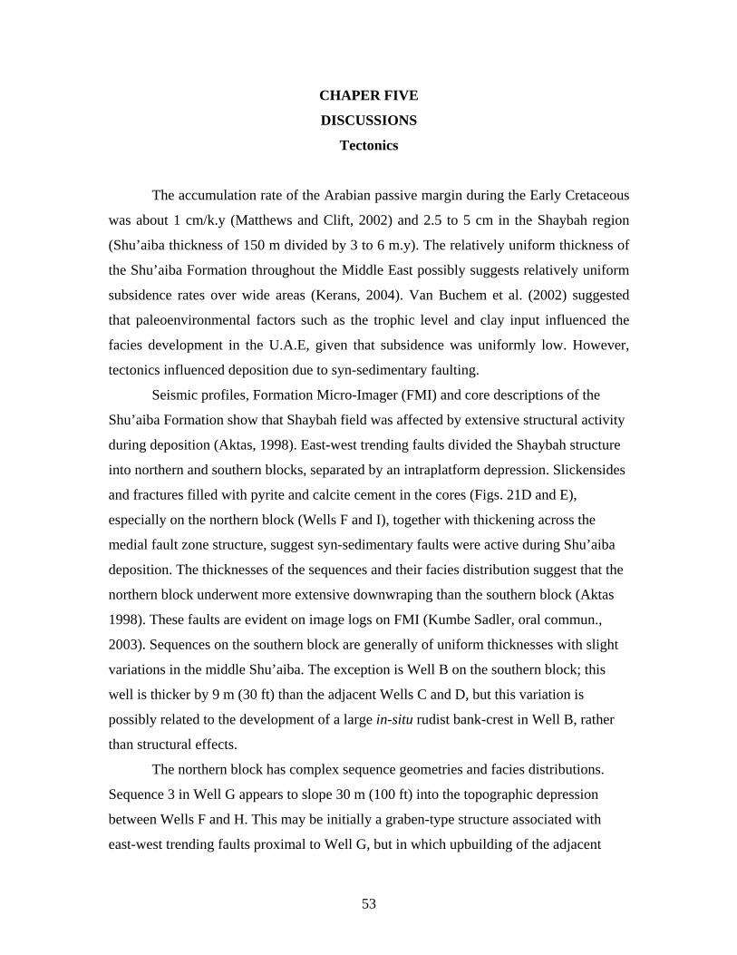
CHAPER FIVE
DISCUSSIONS
Tectonics
The accumulation rate of the Arabian passive margin during the Early Cretaceous
was about 1 cm/k.y (Matthews and Clift, 2002) and 2.5 to 5 cm in the Shaybah region
(Shu’aiba thickness of 150 m divided by 3 to 6 m.y). The relatively uniform thickness of
the Shu’aiba Formation throughout the Middle East possibly suggests relatively uniform
subsidence rates over wide areas (Kerans, 2004). Van Buchem et al. (2002) suggested
that paleoenvironmental factors such as the trophic level and clay input influenced the
facies development in the U.A.E, given that subsidence was uniformly low. However,
tectonics influenced deposition due to syn-sedimentary faulting.
Seismic profiles, Formation Micro-Imager (FMI) and core descriptions of the
Shu’aiba Formation show that Shaybah field was affected by extensive structural activity
during deposition (Aktas, 1998). East-west trending faults divided the Shaybah structure
into northern and southern blocks, separated by an intraplatform depression. Slickensides
and fractures filled with pyrite and calcite cement in the cores (Figs. 21D and E),
especially on the northern block (Wells F and I), together with thickening across the
medial fault zone structure, suggest syn-sedimentary faults were active during Shu’aiba
deposition. The thicknesses of the sequences and their facies distribution suggest that the
northern block underwent more extensive downwraping than the southern block (Aktas
1998). These faults are evident on image logs on FMI (Kumbe Sadler, oral commun.,
2003). Sequences on the southern block are generally of uniform thicknesses with slight
variations in the middle Shu’aiba. The exception is Well B on the southern block; this
well is thicker by 9 m (30 ft) than the adjacent Wells C and D, but this variation is
possibly related to the development of a large in-situ rudist bank-crest in Well B, rather
than structural effects.
The northern block has complex sequence geometries and facies distributions.
Sequence 3 in Well G appears to slope 30 m (100 ft) into the topographic depression
between Wells F and H. This may be initially a graben-type structure associated with
east-west trending faults proximal to Well G, but in which upbuilding of the adjacent
54
banks increased the relief. Sequences 4 and 5 in Well G suggest this depression persisted,
with large units of skeletal packstone debris (fore-bank) shed from nearby rudist banks in
Wells F and H.
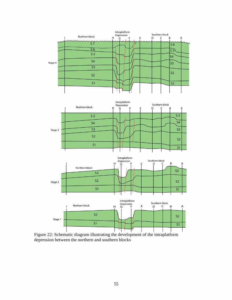
Assuming that the correlation of the sequences between the northern and southern
blocks is correct, then the history of fault movement can be determined. Reconstruction
of sequences on the northern and southern blocks (Fig. 22) suggests that Sequence 1, with
its blanket geometry, was deposited without any major structural effects. Sequence 2 also
initially had a blanket-like geometry, but in the highstand of sequence 2, small east-west
growth faults may have been initiated that promoted upbuilding of Lithocodium platform
on both the northern and southern blocks and sediment starvation in the intraplatform
depression. The block containing Well F moved up slightly relative to the southern block
in order to bring the top of sequence 3 in well F to the same elevation as on the southern
block. Also, during sequence 3 the whole of the northern block may have moved up
slightly relative to the southern block. Sequence 4 appears to have been stable as the
sequences in both blocks have uniform thicknesses except in Well G where the graben
provided excess accommodation. In sequence 5, the northern block may have moved
down slightly relative to the southern block. If the sequence correlations are correct,
major subsidence of the northern block relative to the southern block occurred during or
after deposition of sequence 6. In sequence 7, the northern block may have dropped, and
provided accommodation space that allowed sequence 7 to develop on the northern block
while the regional unconformity was initiated on the relative high southern block.
Alternatively, if both sequences 6 and 7 of the northern block are equal to sequence 6 on
the southern block, then the northern block subsidence likely continued through
sequences 6 and 7, and deposition occurred on both blocks, and terminated at the same
time. With relative sea level fall at the end of the Early Aptian, both northern and
southern blocks became emergent.
Shu’aiba Hierarchy
Composite Sequence:
55
Figure 22: Schematic diagram illustrating the development of the intraplatform depression between the northern and southern blocks
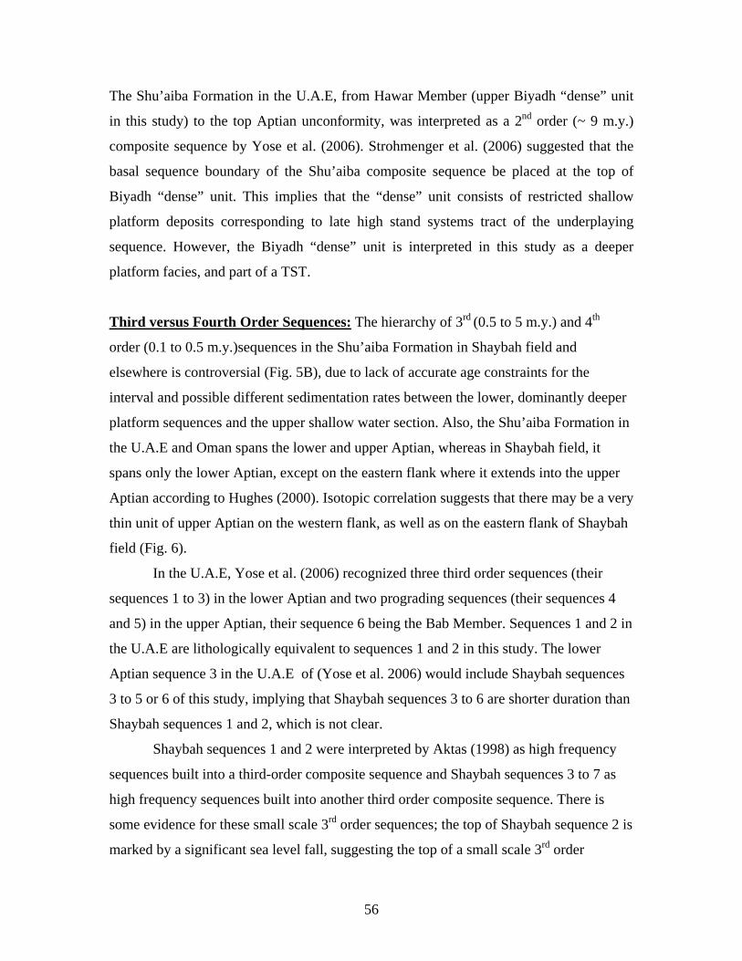
56
The Shu’aiba Formation in the U.A.E, from Hawar Member (upper Biyadh “dense” unit
in this study) to the top Aptian unconformity, was interpreted as a 2nd order (~ 9 m.y.)
composite sequence by Yose et al. (2006). Strohmenger et al. (2006) suggested that the
basal sequence boundary of the Shu’aiba composite sequence be placed at the top of
Biyadh “dense” unit. This implies that the “dense” unit consists of restricted shallow
platform deposits corresponding to late high stand systems tract of the underplaying
sequence. However, the Biyadh “dense” unit is interpreted in this study as a deeper
platform facies, and part of a TST.
Third versus Fourth Order Sequences: The hierarchy of 3rd (0.5 to 5 m.y.) and 4th
order (0.1 to 0.5 m.y.)sequences in the Shu’aiba Formation in Shaybah field and
elsewhere is controversial (Fig. 5B), due to lack of accurate age constraints for the
interval and possible different sedimentation rates between the lower, dominantly deeper
platform sequences and the upper shallow water section. Also, the Shu’aiba Formation in
the U.A.E and Oman spans the lower and upper Aptian, whereas in Shaybah field, it
spans only the lower Aptian, except on the eastern flank where it extends into the upper
Aptian according to Hughes (2000). Isotopic correlation suggests that there may be a very
thin unit of upper Aptian on the western flank, as well as on the eastern flank of Shaybah
field (Fig. 6).
In the U.A.E, Yose et al. (2006) recognized three third order sequences (their
sequences 1 to 3) in the lower Aptian and two prograding sequences (their sequences 4
and 5) in the upper Aptian, their sequence 6 being the Bab Member. Sequences 1 and 2 in
the U.A.E are lithologically equivalent to sequences 1 and 2 in this study. The lower
Aptian sequence 3 in the U.A.E of (Yose et al. 2006) would include Shaybah sequences
3 to 5 or 6 of this study, implying that Shaybah sequences 3 to 6 are shorter duration than
Shaybah sequences 1 and 2, which is not clear.
Shaybah sequences 1 and 2 were interpreted by Aktas (1998) as high frequency
sequences built into a third-order composite sequence and Shaybah sequences 3 to 7 as
high frequency sequences built into another third order composite sequence. There is
some evidence for these small scale 3rd order sequences; the top of Shaybah sequence 2 is
marked by a significant sea level fall, suggesting the top of a small scale 3rd order
57
sequence. The top of sequence 5, marked locally by erosion and emergence may be the
top of another small scale third order sequence composed of sequences 3 to 5 with the
MFS in sequence 4. This then suggests that sequences 6 and 7 may form part of another
small scale third order sequence capped by the unconformity on the platform and the
progradation of sequence 6 being the lowstand and sequence 7 mark the MFS and the
highstand.
Although it could be argued that sequences 3 to 7 may be shorter duration than
sequences 1 and 2, because the sedimentation rate are likely to have been higher within
the rudist buildups (sequences 3 to 6) than on the deeper platform (sequences 1 and 2),
with its condensed sections with planktic forams. However, sedimentation likely was
more continuous on the deeper platform, which did not become emergent; in contrast, the
shallower water, rudist buildup sequences likely were separated by increasingly longer
periods of non-deposition up-section. Thus, it is not possible to assign durations to the
sequences based on their thicknesses without additional information. To avoid this
problem, no time duration was implied for the durations of sequence 1 to 7 during the
initial phase of this work. That sequences are roughly the same duration, (rather than a
mix of 3rd and 4th order sequences) is suggested by the sea level curve of Rohl and Ogg
(1996, 1998), who show 7 high frequency sequences in this time interval from the Pacific
atolls.
The approximately 3 to 4 m.y. duration of the Shu’aiba interval (Yose et al.
2006), suggest that the 7 Shu’aiba sequences might be approximately 400 k.y. duration,
and so are likely to be 4th order (high frequency) sequences. This interpretation differs
from the standard interpretation of sequences 1 and 2 being 3rd order (e.g. Yose et al.
2006). It could be argued that Shaybah sequences 1 and 2 are bounded into a larger scale
sequence, whose top marks a regional sea level fall (Aktas 1998 and Hughes 2000).
However, the parasequences backstep in sequence 2 rather than prograde, suggesting that
accommodation exceeded sedimentation. The maximum flood of sequence 2 is beneath
the sequence 2 planktic foram mudstone, suggesting that the upper part of sequence 2 is
part of the composite early highstand. Shaybah sequences 3 to 7 appear to be the
highstand of the composite sequence, and may make up a 3rd order sequence. Sequences
6 and 7 might be the platform equivalent of the late highstand part of a younger 3rd order
58
sequence (equivalent to sequence 4 of Yose et al. 2006). This would be compatible with
evidence of flooding in Shaybah sequence 7. However, it could be argued that sequences
6 and 7 are merely the upper part of a 3rd order highstand composed of Shaybah
sequences 3 to 7.
Parasequences: The duration of parasequences is difficult to evaluate as they rarely are
regionally mapable especially over the rudist buildups. However, using the maximum
number of parasequences observed on the platform (5 in S1; 5 in S2; 3 in S3; 3-6 in S4 in
the intraplatform depression; 3 in S5; 4 in S6 and 5 in S7) for a total of about 30
parasequences. Given the 3 to 4 m.y. duration of the succession, this would suggest that
the parasequences might be ~ 100 k.y. cycles, perhaps driven by short term eccentricity.
Interpretation of Sequences
Shu’aiba composite sequence:
Shaybah sequences 1 and the lower part of sequence 2 of the Shu’aiba composite
sequence are regional transgressive units deposited during long term relative sea-level
rise during which sedimentation lagged accommodation, until the significant sea level fall
marking the termination of sequence 2. Shaybah sequences 3 to 5 are early highstand
with mainly aggradation of the rudist buildups, becoming slightly progradational in the
upper part of sequence 5, where sedimentation exceeded accommodation. Shaybah
sequences 6 and 7 are late highstand with continued, slight basinward progradation into
the intrashelf basin, and likely marks the major relative sea level fall after the early
Aptian.
Sequence 1 interpretation:
The sequence boundary of sequence 1 (upper Biyadh Formation reservoir unit)
developed on the underlying highstand unit of fine skeletal packstone with local rudist
Glassomyophorus and Agriopleura, indicating shallowing up and relative sea-level fall.
Deposition of sequence 1 (Biyadh “dense” unit) was initiated with relative sea level rise
and widespread deposition of the sheet-like unit of deeper platform, dark, shaly
Palorbitolina carbonate. The MFS beneath the thin light gray mudstone and low gamma
59
ray response indicates deeper conditions in sub-photic zones and widespread deposition
of pelagic foram lime mudstone (~ > 60 m water depth). This MFS is different than the
MFS (K70) of Sharland et al. (2001) that was picked based on the high gamma ray
response of the thin black shale at the top of Biyadh “dense” unit. High organic
productivity in sequence 1 may have been due to the influx of river-borne nutrients and
fine clay, which resulted in dark organic rich-carbonate. Upward shallowing due to
sedimentation, along with sea-level fall culminated in deposition of a sheet-like unit of
light-colored Lithocodium miliolid wackestone/packstone (15 to 25 water depth) on a
shallow open algal platform (Hughes, 2000). There is no evidence of a rudist rim at this
time, at least for the wells that penetrated the margin.
Sequence 2 interpretation:
The sequence 2 boundary developed conformably on the underlying algal
platform. This was followed by rapid sea level rise and deposition of a thin, upward
deepening unit of Lithocodium and Palorbitolina carbonates (TST), culminating in
widespread deepening and deposition of several meters of planktic foram mudstone over
the region. This planktic mudstone, with its low gamma ray response, appears to be the
deepest water facies in the Shu’aiba platform succession, marking the MFS of sequence 2
and possibly a regional MFS for the large scale Shu’aiba composite sequence (cf. Yose et
al. 2006). The pale color of this MFS may indicate non-stratified, oxygenated conditions
even though water depths were considerable. Aktas et al. (1998) suggested that this MFS
was the major drowning event for the lower Shu’aiba member. These Early Cretaceous
planktic forams may have lived in shallower water than modern planktic forams, thus
water depth may not have been excessive (Hughes, personal comun, 2005). Subsequent
relative sea level fall and upward shallowing was associated with possible backstepping
of Lithocodium-bearing parasequences and development of two broad mounds separated
by a trough or “pass” within the developing fault zone between the developing northern
and southern blocks. The pass was due to sedimentation starvation and deposition of a
thinned succession here, dominated by open marine Palorbitolina while the adjacent
platforms built upward. Sedimentation rate was slightly exceeded by accommodation
over the platforms, except toward the crest, causing parasequences to backstep (Fig. 8B).
60
The facies successions of sequence 2 generally record deposition under low energy
conditions, with low sedimentation rates (Aktas, 1998).
Sequence 3 interpretation:
The basal sequence boundary of sequence 3 was developed as a result of rapid
seal level fall of tens of meters (Hughes, 2003 ; Yose et al. 2006). This brought the algal
platform top into shallow water, allowing widespread deposition of Glossomyophorus
rudist facies, along with deeper coral facies locally on the platform flanks. It is possible
that the rudist rims were localized over the edge of fault blocks, and differentiated the
platform into lagoon, back-bank and fore-bank (Hughes, 2005). Within the intraplatform
depression, detrital rudist facies were deposited. These rudist facies were assigned to
sequence 3 rather than 2, because of the general absence of rudists bordering the
sequence 2 algal platform. Transgression initiated the rudist barrier along the eastern
margin, and bordering the intraplatform depression. During highstand, the interior of the
platform deepened to form Lithocodium wackestone, and highstand rudist barrier crest
developed along eastern, southern and northern margins, but the western margin likely
remained open and site of Lithocodium deeper platform facies (Fig. 16). This may be due
to eastern and northern margins being the windward side facing the deeper basin, while
the western side was shallow, and in a leeward setting. The prevailing easterly winds in
the tropics would support the eastern and northern margins being windward (Fig. 4B).
Well K in the northern block has distinctive reservoir facies, of rounded mud-free
caprinid rudist rudstone transported from the rudist buildups (Well H). These facies
formed in back-shoal settings associated with high energy agitated environments or
possibly channel complexes with currents winnowing fine matrix. The large thickness
and geometry of this unit (Fig. 8B) which occupies lows relative to the adjacent wells
may support a channel interpretation. Kerans (2004) described similar facies between the
rudist banks in Al Huwaisah field and interpreted them as a channel-fill with long-
focused current energy.
Sequence 4 interpretation:

61
The local erosional surface of the basal boundary of sequence 4 (Wells A and F)
(Figs. 20D and E) indicates local, high topography on the buildups, which might have
been exposed for a short time or subjected to marine erosion, due to relative sea level fall.
Rudist bank-crest and back-bank facies were re-established on the site of the sequence 3
rudist banks, which probably formed antecedent highs around the platform (Fig. 17). The
deep lagoonal mudstone on the north western flank, Palorbitolina mudstone on the
southeastern flank and widespread Lithocodium wackestone on the southern block
indicate significant deepening of the platform. The lack of data behind the deep lagoonal
mudstone on the northwestern flank makes it difficult to predict whether this lagoonal
facies was rimmed on the western margin, as suggested by previous work (Aktas et al.
1999 ; Hughes 2000) or was open, which is favored on the basis of the open-marine
lagoon fills.
Sequence 5 interpretation:
The subtle sequence boundary at the base of sequence 5 indicates a small drop in
sea level resulted in shallowing of the banks to sea level with little evidence of
emergence. Subsequent sea level rise caused the barrier to re-develop over the pre-
existing rudist barrier, along the northern and eastern margin and bordering the
intraplatform depression (Fig. 18). A rim appears to have developed at least along the
western margin of the platform on the northern block (Well I), and perhaps completely
rimming the platform. These facies prograded out over their fore-bank deposits in the late
highstand. This may have caused the disappearance of the Lithocodium facies and deep-
to-shallow lagoon facies to develop in the lagoonal depressions. The well developed in
situ rudists in sequence 5 are due to gradual shallowing of the whole platform throughout
sequences 1 to 5. Local exposure surfaces were infiltrated by red mudrock (e.g. Well B)
(Fig. 20F), thin beds of rudist rudstone were formed on the barrier crest and the platform,
prograded eastward (basinward), due to fall in relative sea level. This terminated rudist
development on the southern block, which likely was in a restricted, shallow setting,
compared to the northern block which extended northward into the intrashelf basin.
Because the platform was becoming shallower up-section, the platform would be
62
subjected to increasing exposure for the same sea level magnitude, perhaps accounting
for the onset of exposure features.
Sequence 6 interpretation:
The following discussion assumes that the correlation is correct for sequence 6
between the northern and southern blocks. Rudist buildups re-established in front of
earlier buildups bordering the northern platform, but formed only isolated patch-banks,
rather than a barrier (Fig. 19). The localized thick rudist facies of the northern block
(Wells G and L), are indicative of more accommodation space being available due to
growth faults between the northern and southern blocks, which dropped the northern
block down relative to the southern block. On the northern block, the rudist banks
prograded basinward from the eastern flanks (Fig. 8 B), as well from the western margin.
This marks the start of the late highstand of the Shu’aiba composite sequence. High
energy rudist buildups did not re-establish on the southern block, which may have had
less accommodation and was more restricted (Fig. 19). On the southern block,
widespread lagoonal fine skeletal packstone with local Agriopleura floatstone banks were
deposited, filling the available accommodation. On both blocks, lagoonal facies filled in
the depressions that were not filled by rudist back-bank facies. High energy rounded
rudstone on top of sequence 6 (Well L) records the relative fall of sea level terminating
sequence 6 deposition.
Sequence 7 interpretation:
Relative sea level fall exposed the southern block, which was not re-flooded
(assuming the uppermost Shu’aiba deposits here are sequence 6). On the northern block,
more accommodation space was available as it continued to subside. This caused
renewed marine flooding and widespread deposition of Agriopleura facies with relative
sea-level rise. Agriopleura rudists re-established locally along the eastern rim, (now
relatively low energy), and peripheral to the intraplatform depression. The rudist facies
along the margin prograded, but did not form the well developed, high energy rudist
banks of earlier sequences. Only locally (Wells G and L) did Offneria rudists develop,
representing late stage rudist progradation for the Shu’aiba composite sequence. The deep
63
lagoonal maximum flooding surfaces with planktic forams of sequence 7 (Well G)
indicate significant relative sea level rise. The Offneria debris in the uppermost part of
Well M on the eastern flank possibly attest to progradation of rudist banks from the
eastern flank; this is reminiscent of the prograding 3rd order sequence 4 of the Shu’aiba
Formation in the U.A.E (Kerans 2004 and Yose et al. 2006).
After deposition of sequence 7, sea level fall exposed the platform for
approximately ~ 4 m.y. (Sharland et al. 2001) to form the regional unconformity on top
of the Shu’aiba Formation in Shaybah field (Fig. 21F). This was accompanied by karsting
and subsequent infill of vugs and caverns within the upper Shu’aiba Formation by
infiltrating fine clastics from the Nahr-Umr shale. As the shelf margin of the Shu’aiba
Formation was subaerially exposed, the intrashelf basin filled with black shaly lime
mudstone and shale of the Bab member (Fig. 8B) (Alsharhan 1985 and 1995). The Bab
member represents the lowstand systems tract of the Late Aptian (Yose et al. 2006).
Paleoclimate and Eustasy
Greenhouse versus Transitional climate:
The Cretaceous time has long been considered as a warm, greenhouse climate.
However, recent studies have shown that the Cretaceous had intervals of global cooling
and warming (Frakes et al. 1995; Johnson et al. 1996). Although there is only limited
evidence for glaciation in the Cretaceous, modeling indicates there were freezing winters
in the continental interiors at high latitude (Barron et al. 1995). Alley and Frakes (2003)
reported on the basis of glacial diamictites, the first known Cretaceous glaciation in South
Australia. Moreover, Matthews and Frohlich (2002) and Immenhauser and Matthews
(2004) suggested that the lower Cretaceous Aptian and Albian sea level cycles were
controlled by glacio-eustatic mechanism driven by eccentricity. They suggested that the
idea of the Cretaceous being a time of global, continuous climatic warmth needed to be
re-evaluated.
Given the duration of ~ 3 to 4 m.y., the seven sequences recognized in the lower
Aptian Shu’aiba Formation in this study appear to be 4th order, high frequency sequences,
approximately 400 k.y. duration. The maximum number of parasequences in the Shu’aiba

64
Formation is about 26 to 30, and given the 3 to 4 m.y. duration, they are likely to be
about 100 k.y. duration. In greenhouse times, cycles are likely dominated by high
frequency, low amplitude sea level changes driven by precession (Read, 1995).
Therefore, one would expect to find many more parasequences in the 3 to 4 m.y.
Shu’aiba composite sequence. It is likely that long-term eccentricity drove the sea-level
changes to form the seven high frequency sequences, while short term eccentricity was
the likely driving mechanism for the parasequences. This is compatible with the
conclusions of Matthews and Frohlich (2002) and Immenhauser and Matthews (2004),
who suggested that the cycles in the Lower Cretaceous are glacio-eustatic and driven by
eccentricity. Rohl and Ogg (1998) documented that the Pacific guyots of Aptian-Albian
age are composed of 100 k.y parasequences grouped into 400 k.y parasequences sets.
Spectral analysis of wireline logs from the guyots indicate a dominant 413 k.y
periodicity, and a subordinate 123 k.y. cyclicity (1998).
The facies stacking and sequence boundaries of sequences 1 and 2 of the Shu’aiba
Formation resulted from rises and falls in sea level of some tens of meters. Also, the
regional drop in sea level at the top of Shu’aiba Formation was probably tens of meters.
These moderate amplitude sea level changes in the Shu’aiba Formation are not
compatible with classic greenhouse sea-level changes, which should be small. Thus, the
Aptian likely was a cooler or transitional period with some ice at the poles (c.f Read
1998).
Local Climate:
The absence of ooids and evaporites, and presence of karst at the top of Shu’aiba
Formation possibly indicate humid climate during deposition of the Shu’aiba Formation.
The well developed rimmed margin on the eastern side of the Shu’aiba buildup is
compatible with this margin being the windward margin, facing the Neo-Tethys Ocean
with its easterly trend winds. The western flank may have been the leeward margin with
relatively low energy (Poulsen et al. 1999) (Fig. 4B). This might account for the early
development of the rudist barrier on the eastern and northern windward margins, and
bordering the intraplatform depression. The later development of the rudist barrier on the
western side would be compatible with this being the leeward margin.
65
Eustatic Controls:
The Arabian platform sea level curve of Haq and Al-Qahtani (2005) (Fig. 23),
records one complete third-order sea level cycle in the lower Aptian. The Shu’aiba
composite sequence probably formed as a result of this Early Aptian sea level cycle. The
Haq and Al-Qahtani chart does not show higher frequency sea level cycles, such as those
recognized in the Shu’aiba Formation. This curve shows sea level rise in the uppermost
Barremian lower Early Aptian; associated with deposition of the transgressive Biyadh
“dense” unit. The maximum flooding surface K70 of Sharland et al. (2001) is the MFS of
the sea level cycle. This K70 MFS is assigned to the top of the Biyadh “dense” unit by
Sharland et al. (2001). In this paper, the major maximum flooding surface was placed in
high frequency sequence 2, at the base of the major planktic foram lime mudstone.
During the highstand with its falling sea level phase of the sea level cycle, Shaybah
sequences 3 to 6, the bulk of the highstand of the Shu’aiba composite sequence were
deposited, which might have initiated unconformity development of the Shu’aiba on the
southern block.
The upper Aptian sea level cycle may have caused renewed flooding of the
Shu’aiba buildup, and deposition of Shaybah sequence 7 on the northern block. However,
deposition in the Shaybah area appears to have ended soon after, with development of the
top Shu’aiba unconformity. The K80 maximum flooding surface of Sharland et al. (2001)
is in the Tar unit of the Bab Member, high in the succession, yet the Shu’aiba equivalents
in the U.A.E show pronounced progradation during much of the late Aptian prior to Bab
deposition, suggesting regional uplift caused a relative sea level fall rather than a rise to
the K80 maximum flooding surface.
Rohl and Ogg (1998) presented high frequency sea level curves for the Aptian
(Fig. 23) based on sequence interpretation of the guyots (drowned atolls) in the Pacific
Ocean. Correlation of the Shaybah sequences to this sea level curve depends on the
validity of the age constraints on the Shu’aiba Formation. Assuming that the Biyadh
“dense” unit is latest Barremian to Early Aptian (van Buchem et al. 2002), then it is likely
that the sea level fall at the base of the Aptian formed the top-Biyadh reservoir sequence
boundary. The first two sea level cycles of Rohl and Ogg (1998) could have generated

66
sequences 1 and 2 of the algal platform, and the significant sea level fall (their Apt. 2
sequence boundary) may have generated the large sea level fall on top of Shu’aiba
sequence 2 and onset of rudist formation of sequence 3. It is tempting to correlate
Shaybah sequences 3, 4 and 5 with their remaining 3 Early Aptian sea level cycles.
However, this would imply that Shaybah sequences 6 and 7 correlate with Rohl and
Ogg’s (1998) two earliest upper Aptian cycles (whose top boundaries are Apt. 6 and 7).
That their cycle 7 terminates in a major sea-level fall would be compatible with the
unconformity on top of Shaybah sequence 7 that exposed the buildup. However, Hughes
(2000) does not consider that any Upper Aptian is present on the platform in Shaybah
field. Whether or not the Shaybah sequences correlate one-for-one with the Aptian record
of the Pacific guyots, nevertheless, both appear to be dominated by 4th order sequences
driven by short and long term eccentricity (1998).
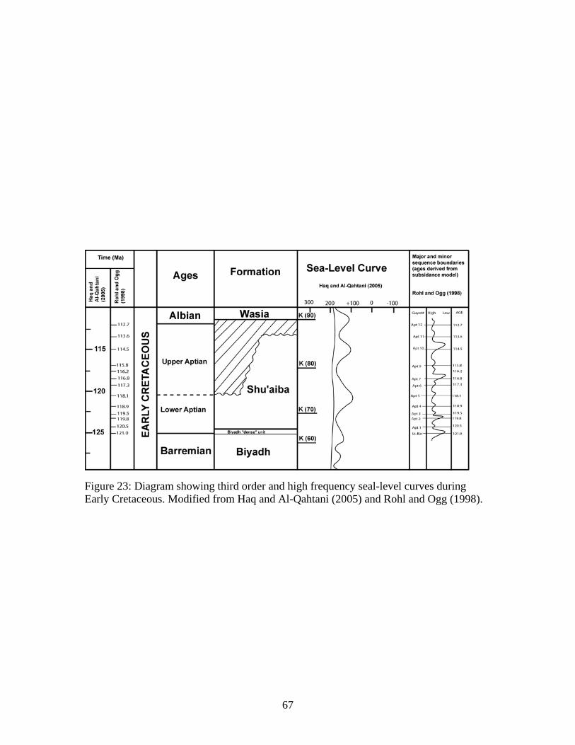
67
Figure 23: Diagram showing third order and high frequency seal-level curves during Early Cretaceous. Modified from Haq and Al-Qahtani (2005) and Rohl and Ogg (1998).
68
CHAPTER SIX
SIGNIFICANCE
This study builds on the work of Aktas (1998) and Hughes (2000), and uses
detailed lithological logs from cores to document facies, to define stacking patterns and
trace sequences through the Shu’aiba platform. This was to generate a more lithologic-
based sequence framework and reservoir model. Such a core-based approach was needed
because the seismic data is poor and biostratigraphic correlation is weak (Hughes 2000).
The sequence stratigraphy is complicated by the development of high frequency
sequences within the Shu’aiba composite sequence, few of which are marked by evidence
of exposure or unconformity development. Tracing of sequence boundaries was difficult
within the rudist-dominated margin, because of the commonly poor facies differentiation.
Sequence boundaries were more easily identified in lagoonal sections, where upward-
shallowing trends were more apparent. Rapid lateral and vertical facies differentiation on
the platform made it difficult to correlate from well to well. Correlation of sequences also
proved a problem in the lower and upper Shu’aiba Formation, due to growth-faulting and
differential upbuilding, which divided the Shu’aiba platform into northern and southern
blocks, separated by an intraplatform depression.
Maximum flooding surfaces were difficult to define, especially within the rudist
margin, where “keep-up” sediment was dominant and no obvious deeper subtidal facies
were developed. The maximum flooding surfaces were better developed within lagoonal
or deep-platform successions, where onset of deposition of fine grained, lower energy,
deeper water facies mark the maximum flooding surfaces. Topography on the Shu’aiba
platform resulted in differentiation of facies, with elevated rudist facies backed by deeper
subtidal lagoons, and a gentle slope into the basin in front of the rudist barrier. The
limited well control and poor quality seismic data hindered tracing of sequences downdip
and into the basin.
The sequence stratigraphic analysis provided a way to tentatively reconstruct the
evolution of the Shu’aiba platform. Re-datuming each sequence on shallow water facies
underlying sequence boundaries allowed the faulting history of the platform to be
69
tentatively reconstructed, although the reconstructions depend on physical correlation of
sequences without biostratigraphic control.
The lower Shu’aiba algal platform in this study has no rudist rimmed around the
structure. The subsequent rudist barrier was interpreted to fringe the Shaybah structure,
with best development on the windward northeastern side, but extending around the
structure in younger sequences. The localization of the rudist barrier around the Shaybah
structure contrasts with earlier interpretations in which the rudist barrier extended
southeastward from the south-eastern margin of the Shaybah structure to form a barrier
between the regional shallow ramp and deeper basin to the north. However, evidence for
the extension of this barrier is weak and based largely on the presence of lagoon-like
facies off the Shaybah structure to the south-east. These may be shallow embayment
facies, and not necessarily behind a rim.
The rudist facies in the Shu’aiba Formation, Shaybah field, formed banks
(accumulations of skeletal carbonate lacking a rigid internal skeletal framework) rather
than reefs (skeletal accumulations with rigid internal skeletal framework). Reefal
boundstones were developed along the ocean-facing margin of the passive margin,
evidence by coral-rudist-microbialite boundstone blocks in fore-slope facies (Greselle
and Pittet 2005). The southern margin of the intrashelf basin containing Shaybah field
may have been slightly restricted compared to the passive margin, thus and only banks
formed.
The prograding late Aptian 3rd order sequences in the late HST of the Shu’aiba
composite sequence in the U.A.E, were not penetrated by wells in Shaybah field.
Whether these are developed off the structure is unclear, although the presence of late
Aptian sediments along the eastern flank of the structure raise the possibility that
additional sequences may be present.
The dominant high frequency sequences in the Aptian of Shaybah field, are
similar to the succession in Pacific guyots of this age where the dominant signal is 413
k.y., associated with long term eccentricity (Rohl and Ogg 1998; Cooper 1998).
Similarly, the duration of the Shu’aiba parasequences is probably ~ 100 k.y. or so, similar
to upward shallowing parasequences of wackestone-packstone in the guyots, and
interpreted to be 95 and 123 k.y. sea level cycles driven by short term eccentricity

70
(Cooper 1998). This appears to be more compatible with moderate ice sheets at the poles
during this time, rather than an ice-free greenhouse world (cf. Matthews and Frohlich
2002). The high frequency sequences in the Shaybah field contrast with the interpretation
in the U.A.E (Yose et al. 2006), where the dominant motif is one of 3rd order sequences
bounded into a composite sequence.

71
CHAPTER SEVEN
CONCLUSIONS
1- The Early Cretaceous, Aptian Shu’aiba Formation in Shaybah field, Saudi Arabia,
is a large rudist-rimmed complex platform (60 km long by 12 km wide, and 150
m thick) that formed on a subtle structural high, extending from a regional ramp
northward into an intrashelf basin. The Shu’aiba buildup is composed of a
northern and southern block separated by an intraplatform depression, bordered
by growth faults.
2- The Aptian succession in Shaybah field is a composite sequence composed of
seven high frequency sequences. These sequences appear to be approximately 400
k.y. (4th order), and were formed by sea level changes driven by long term
eccentricity. Up to 30 parasequences are developed in the succession but are
difficult to trace regionally. They likely are of 100 k.y. duration, and formed by
sea level changes driven by short term eccentricity. This dominance of long-and
short term eccentricity cycles also characterized the Early Cretaceous of Pacific
guyots. The lack of precessional cycles in the Shu’aiba Formation and the
dominant eccentricity driven cycles is compatible with a cooler, Early Cretaceous
climate with some ice sheets at the poles rather than a greenhouse climate.
3- Shaybah sequences 1 and 2 are composed of Palorbitolina and Lithocodium
packstone and wackestone and formed on an open, initially low relief platform
that differentiated into two separate platforms with increased relief. Maximum
flooding events are evidenced by thin blankets of planktic foram lime mudstone.
Sequence 1 and the lower part of sequence 2 represent the transgressive phase for
the Shu’aiba composite sequence. Sequences 3 and 4 were characterized by initial
establishment of rudist buildups on the margin surrounded by lagoonal and back-
bank facies on the platform interior; the leeward western margin may have had a
more poorly developed rudist facies tract; sequence 4 has relatively deep lagoon
facies during the maximum flood. Sequence 5 has well developed rudist barrier
facies, including large rudist Offneria facies locally capped by rounded rudist
rudstone. Sequences 3 to 5 comprise the early highstand of the composite
72
sequence. Sequences 6 and 7 (the latter confined to the northern block) have
progradational, locally developed rudist facies, and widespread deep to shallow
lagoonal, fine skeletal packstone. Sequences 6 and 7 comprise part of the late
highstand of the composite sequence, and show evidence of deepening in the
reported increased planktic forams. Accommodation appears to have been
generated on the northern block during deposition of sequences 6 or 7 by growth
faulting during deposition.
4- The termination of Shu’aiba deposition on the Shaybah platform was associated
with sea level fall and development of the Late Aptian unconformity on top of the
Shu’aiba Formation. Terrigenous muds infiltrated into the Shu’aiba sediments
beneath the unconformity and filled karst vugs during deposition of the Nahr-Umr
Shale.
73
REFERENCES
Aktas, G. 1998. Geological Framework of Shu’aiba reservoir in Shaybah field: Sequence Stratigraphy, Depositional Model and Reservoir Quality. Saudi Aramco internal report. Aktas, G., Hughes, G.W., Abu-Bashait, A.J., Al-Garni, S. 1999. Stratigraphic framework of Shu’aiba Formation, Shaybah Field, Saudi Arabia; a basis for reservoir development of an Aptian carbonate ramp complex. American Association of Petroleum Geologists. Annual Convention 1999, San Antonio. Aktas, G., Hughes, G.W., Abu-Bashait, A.J., Al-Garni, S. 2000. Stratigraphic framework of Shu’aiba Formation, Shaybah Field, Saudi Arabia; a basis for reservoir development of an Aptian carbonate ramp complex. 4th Middle East Geosciences Conference. GEO 2000, Abstract. GeoArabia, V.5, no. 1, p.11. Alley, N.F, Frakes, L. A. 2003. First known Cretaceous glaciation: Livingston tillite member of the Cadna-Owie formation, South Australia. Australian Journal of Earth Sciences. 50, p. 139-144. Alsharhan, 1985. Depositional environment, reservoir units evolution, and hydrocarbon habitat of Shuaiba Formation, lower Cretaceous, Abu Dhabi, United Arab Emirates. AAPG Bulletin, V. 69, No. 6, P. 899-912. Alsharhan, 1995. Facies variation, diagenesis, and exploration potential of the Cretaceous rudist-bearing carbonate of the Arabian Gulf. AAPG Bulletin, V. 79, No. 4, P. 531-550. Blackey, R. 2005. Global paleogeographic maps for Early Cretaceous. From http://www2.nau.edu/~rcb7. Cooper, P. 1998. Sedimentary cycles in carbonate platform facies: Fourier analysis of geophysical logs from ODP Sites 865 and 866. in Camoin, G. F., Davies, P.J., 1998. Reefs and carbonate platforms in the Pacific and Indian Oceans. Special Publication 25. International Association of Sedimentologists.77-92. Frakes, L. A. 1999. Estimating the global thermal state from Cretaceous Seas
surface and continental temperature. In Barrera, E., Johnson, C.C., Evolution of the Cretaceous Ocean-Climate System Geological Society of America. Special paper 332. Pg. 49-57. Greselle, B., Pittet, B., 2005. Fringing carbonate platform at the Arabian Plate margin in northern Oman during the Late Aptian-Middle Albian: Evidence for high- amplitude sea-level changes. Sedimentary Geology 175 (2005) 367-390.
74
Hay, W. W., DeConto, R.M, Wold, C. N, Wilson, K. M, Voigt, S, Schulz, M, Wold, A. R, Cullo, W. C, Ronov, A. B, Balukhovsky, A. N, Soding, E. 1999. Alternative global Cretaceous paleogeography. Geological Society of America. Special Paper 332. Pg. 1-47. Harris, P.M, Frost S.H, Seiglie G.A, Schneidermann, N. 1984. Regional unconformities and depositional cycles, Cretaceous of the Arabian Peninsula. American Association of Petroleum Geosciences, Memoir, v. 36, p. 67-80. Handford, C.R. and R.G. Loucks 1993. Carbonate depositional sequences and system tract – responses of carbonate platforms to Relative Sea-Level Changes. American Association of Petroleum Geologists, Memoir no. 57, p. 3-41. Haq, B. U, Al-Qahtani, A. 2005. Phanerozoic cycles of sea-level change on the Arabian Platform. GeoArabia. Pg. 127-158. Hughes, G.W. 1999. The Shu’aiba Formation at Shaybah Field: Summary of macropalaeontological and Micropalaeontological evidence for each layer. Saudi Aramco internal report. Hughes, G.W. 2000. Bioecostratigraphy of the Shu’aiba Formation, Shaybah field, Saudi Arabia. GeoArabia, Vol. 5, No. 4, Pg. 545-578. Hughes, G.W., Siddiqui, S., Sadler, R.K. 2003. Shu’aiba rudist taphonomy using computerized tomography and image logs, Shaybah Field, Saudi Arabia. GeoArabia, 8, 585-596. Hughes, G.W. 2003. Agriopleura Morphotypes of the Lower Aptian Shu’aiba Formation of Saudi Arabia. 2003. Geologia Croatica. 56/2. p. 133-138. Zagreb. Hughes, G.W. 2005. Micropalaeontological dissection of the Shu’aiba reservoir, Saudi Arabia. From: POWELL, A.J. & RIDING, J.B. (eds). Recent development in applied biostratigraphy. The Micropalaeontological Society, Special Publications, 69-90. 1747-602X/$15.00 Immenhauser, A, Matthews, R. K. 2004. Albian sea-level cycles in Oman: The ‘Rosetta Stone’ approach. GeoArabia, Vol. 9, No. 3. Kerans, C., and Tinker, S. W. 1997. Sequence stratigraphy and characterization of carbonate reservoirs: Society of Economic Paleontologists and Mineralogists Short Course Notes #40, 165 p. Kerans, C. 2004. Regional Stratigraphic Setting of Shuaiba Reservoir- A core-based perspective. Shu’aiba workshop, GeoArabia. Unpublished report.

75
Lehmann, C, Osleger, D. A & Montanez, I. P. 1998. Controls on cyclostratigraphy of lower Cretaceous carbonates and evaporates, Cupido and Coahuila Platforms, Northestern Mexico. Jurnal of Sedimentary Research, Vol. 68, No. 6, p. 1109- 1130. Matthews, R. K & Frohlich, C. 2002. Maximum flooding surfaces and sequence boundaries: comparisons between observations and orbital forcing in the Cretaceous and Jurassic (65-190 Ma). GeoArabia, V. 7, No. 3. Pg. 502-538. Poulsen, C.J., Barron, E.J., Johnson, C.C., and Fawcett, P., 1999, Links between major climate factors and regional oceanic circulation in the mid-Cretaceous. In Barrera, E., and Johnson, C.C., eds., Evolution of the Cretaceous Ocean-Climate Systems: Boulder, Colorado, Geological Society of America, Special papers 332. P 73-89. Read, J.F., 1995, Overview of carbonate platform sequences, cyclestratigraphy and reservoir in greenhouse and icehouse worlds, in Read, J.f., Kerans, C., Weber,L.Jl, Sarg, J.F., and Wright F.w., Milankovitch Sea Level Changes, Cycles and Reservoirs on Carbonate Platforms in Greenhouse and Icehouse Worlds: SEPM, Short Course Notes no. 35,p.1-102. Read, J.F., 1998, Phanerozoic carbonate ramps from greenhouse, transitional and ice- house worlds: clues from field and modeling studies. In: Wright, V.P. & Burchette, T.P. (eds) Carbonate Ramps. Geological Society, London, Special Publications, 149, 107-135. Rohl, U., Ogg, J.G. 1998. Aptian-Albian eustatic sea-levels. Spec. in Camoin, G. F., Davies, P.J., 1998. Reefs and carbonate platforms in the Pacific and Indian Oceans. Special Publication 25. International Association of Sedimentologists.77- 92. Russell, D.S. 2001. Reservoir characterization of the Shuaiba Formation (Lower Cretaceous) Abu Dhabi, United Arab Emirates and Jabel Akhdar, Sultanate of Oman. PHD thesis, University of Aberdeen. Russell, D. S., Akbar, M. & Vissapragada, B. & Walkden, G. M. 2003. Rock types and permeability prediction from dipmeter and image logs: Shuaiba reservoir (Aptian), Abu Dhabi. AAPG Bulletin, V. 86, No. 10. pp. 1709-1732. Saggaf, M. 1998. Shaybah guidebook. A reservoir characterization perspective. Contributors: Nebrija, L., Aktas, G., Amos, S. W., Al-Ghamdi, J., Hauser, E.C., Heil, R. J., Hughes, W. G., Al-Khalifa, M.A., Al-Qahtani, J.A., Sadler., R., Saggaf, M.M., Triebwasser, H.L. Northern Fields Characterization Division. Reservoir Characterization Department, Exploration Organization, Saudi Aramco internal report.
76
Sarg, J.F., 1988, Carbonate sequence stratigraphy, in Wilgus, C.K., Hatings, B.S., Kendall, C.G.St.C., Posamentier, H.W., Ross, C.A., and Van Wagoner, J.C., Sea- Level Changes: An Integrated Approach: SEPM, Special Publication 42, p. 155- 181. Scotes, C.R., Gahagan, L. M., and Larson, R. L., 1989. Plate tectonic reconstructions of the Cretaceous and Cenozoic ocean basins, in Scotese, C.R. and Sager, W.W. (eds), Mesozoic and Cenozoic Plate reconstructions, Elsevier, Amsterdam, p. 27- 48. Sharland, P.R, Archer, R., Casey, D.M, Davies, R.B., Hall, S.H, Heward, A.P, Horbury A.D., Simmons, M.D. 2001. Arabian Plate sequence stratigraphy. GeoArabia Special Publication 2. Stoll, H.M, Schrag, D.P. 2000. High-resolution stable isotope records from the Upper Cretaceous rocks of Italy and Spain: Glacial episodes in a greenhouse planet?. Geological Society of America Bulletin. v. 112; no.2; p. 308-319. Strohmenger, C. J., L. J. Weber, A. Ghani, K. Al-Mehsin, O. Al-Jeelani, A. Al- Mansoori, T. Al-Dayyani, L. Vaughan, S. A. Khan, and J. C. Mitchell, 2006, High-resolution sequence stratigraphy and reservoir characterization of upper Thamama (Lower Cretaceous) reservoir of a giant Abu Dhabi oil field, United Arab Emirates, in P. M. Harris and L. J. Weber, eds., Giant hydrocarbon reservoir of the world: From rocks to reservoir characterization and modeling, p. 141-173. Tucker, M.E. & Wright, P.V. Carbonate sedimentology. 1990. (C)By Blackwell Science Ltd. Vail, P.R., R.M. Mitchum, R.G. Todd, J.M. Widmier, S. Thompson III, J.B. Sangree, J.N. Bubb, and W.G. Hatlelid 1977. Seismic stratigraphy and global changes of Sea-level. American Association of Petroleum Geologists, Memoir 26, p. 49-212. Van Buchem, F.S.P., Pittet, H. Hillgartner, J. Grotsch, A. I. Al Mansouri, I. M. Billing, H.H.J. Droste, W.H. Oterdoom and M. Van Steenwinkel, 2002, High- resolution sequence stratigraphic architecture of Barremian/ Aptian carbonate in northern Oman and the United Arab Emirates (Kharaib and Shuaiba Formations): GeoArabia, V. 7, p. 461-500. Weber, L.J & Sarq, J.F & Wright F.M. 1995. Sequence stratigraphy and reservoir delineation of the Middle Pennsylvanian (Desmoinesian), Paradox basin and Aneth field, southwestern USA.SEPM short course No. 35. p. 1-60. Yose, A. A., A. S. Ruf, C.J. Strohmenger, J. S. Schuelke, A. Gombos, I. Al-Hosani, S. Al-Maskary, G. Gloch, and Y. Al-Mehairi, 2006, Volume based characterization of a heterogeneous carbonate reservoir, Lower Cretaceous, Abu

77
Dhabi (U.A.E), in P. M. Harris and L. J. Weber, eds., Giant hydrocarbon reservoir of the world: From rocks to reservoir characterization and modelling, p.175-214. Ziegler, M.A. 1976. Rocks and fabrics in the lower Cretaceous Shu’aiba Formation of the Shaybah field and in eastern Saudi Arabia. Internal report. Saudi Aramco.
Related Documents