Facies Interpretation from Well Logs: Applied to SMEKS Field, Offshore Western Niger Delta Olumuyiwa Odundun 1 ; Matthew Nton 1 1 Department of Geology, University of Ibadan, Ibadan, Nigeria SUMMARY This paper presents the interpretation of data from well-logs and core samples obtained from SMEKS Field, offshore western Niger Delta. The study aims at using well log approach in establishing the sedimentary facies, their successions and environments of deposition in this field. In addition, a well to well correlation and reservoir quality assessment were undertaken. The palaeodepositional environments in the field were deduced by combining gamma ray log trends with core data. Lithofacies interpretation was carried out with Schlumberger’s Petrel 2010 software package using the gamma ray, effective porosity and r esistivity logs obtained from four wells. Correlation technique was used to delineate the subsurface trends of these facies. Lithofacies calculation shows that the entire well interval consists of sand, silt and shale. Four log facies were recognized in the study area: irregular log trends representing deep marine clay; a funnel-shaped facies representing a crevasse splay; a cylindrical-shaped facies representing slope channel-fills and turbidite fans, and a bell-shaped facies representing transgressive marine shelf. Four reservoir bodies were discovered in the field. Sand bodies are 50 m thick or less and are characteristically poorly sorted to well sorted, fine clayey sands- with some conglomerate and shale pebbles. A qualitative reservoir evaluation shows that porosity values range from 20 to 37% while the permeability range from 524 to 9600 md. The porosity and permeability are better developed in areas of sand bodies deposited in the slope channel environment. There is a good hydrocarbon bearing potential of the deep sea channel sands coupled with the complex fault system of which the distal Niger Delta province is associated. INTRODUCTION The Niger Delta basin has spectacularly maintained a thick sedimentary apron and salient petroleum geological features favorable for petroleum accumulation from the onshore through the continental shelf and to the deepwater terrains. The onshore and continental shelf Niger Delta are being explored for more than half a century now. However, exploration activities are gradually being shifted to the deep offshore to unveil its hydrocarbon potential. The deep sea channel sands are the main exploration target in this section of the Niger Delta (Whiteman, 1982). A lot of information about the sediments and sedimentary processes is contained in well logs. Sediments in different paleoenvironments display characteristic log motifs. As a result, borehole logs are widely used to interpret sedimentary facies (Weber, 1971). The logs used in this study include Gamma Ray (GR), true resistivity (RD/AHT90/P40H), and effective porosity (PIGE). Information about the sediments and sedimentary processes from the above logs may not be sufficient alone, due to some lithologies having similar natural radioactivity and electrical properties. Information from cuttings and cores is therefore often an essential component

Welcome message from author
This document is posted to help you gain knowledge. Please leave a comment to let me know what you think about it! Share it to your friends and learn new things together.
Transcript

Facies Interpretation from Well Logs: Applied to SMEKS Field, Offshore Western Niger Delta
Olumuyiwa Odundun
1; Matthew Nton
1
1 Department of Geology, University of Ibadan, Ibadan, Nigeria
SUMMARY
This paper presents the interpretation of data from well-logs and core samples obtained from SMEKS Field, offshore western Niger Delta.
The study aims at using well log approach in establishing the sedimentary facies, their successions and environments of deposition in this
field. In addition, a well to well correlation and reservoir quality assessment were undertaken.
The palaeodepositional environments in the field were deduced by combining gamma ray log trends with core data. Lithofacies
interpretation was carried out with Schlumberger’s Petrel 2010 software package using the gamma ray, effective porosity and resistivity
logs obtained from four wells. Correlation technique was used to delineate the subsurface trends of these facies.
Lithofacies calculation shows that the entire well interval consists of sand, silt and shale. Four log facies were recognized in the study area:
irregular log trends representing deep marine clay; a funnel-shaped facies representing a crevasse splay; a cylindrical-shaped facies
representing slope channel-fills and turbidite fans, and a bell-shaped facies representing transgressive marine shelf. Four reservoir bodies
were discovered in the field. Sand bodies are 50 m thick or less and are characteristically poorly sorted to well sorted, fine clayey sands-
with some conglomerate and shale pebbles. A qualitative reservoir evaluation shows that porosity values range from 20 to 37% while the
permeability range from 524 to 9600 md. The porosity and permeability are better developed in areas of sand bodies deposited in the slope
channel environment. There is a good hydrocarbon bearing potential of the deep sea channel sands coupled with the complex fault system
of which the distal Niger Delta province is associated.
INTRODUCTION
The Niger Delta basin has spectacularly maintained a thick sedimentary apron and salient petroleum geological features favorable for
petroleum accumulation from the onshore through the continental shelf and to the deepwater terrains. The onshore and continental shelf
Niger Delta are being explored for more than half a century now. However, exploration activities are gradually being shifted to the deep
offshore to unveil its hydrocarbon potential. The deep sea channel sands are the main exploration target in this section of the Niger Delta
(Whiteman, 1982).
A lot of information about the sediments and sedimentary processes is contained in well logs. Sediments in different paleoenvironments
display characteristic log motifs. As a result, borehole logs are widely used to interpret sedimentary facies (Weber, 1971). The logs used in
this study include Gamma Ray (GR), true resistivity (RD/AHT90/P40H), and effective porosity (PIGE).
Information about the sediments and sedimentary processes from the above logs may not be sufficient alone, due to some lithologies
having similar natural radioactivity and electrical properties. Information from cuttings and cores is therefore often an essential component
of any lithologic analysis. From the combined core description and wireline log data, it is commonly possible to generate a series of
(wireline) log facies. Such log facies may be used to describe the reservoir section in uncored, but logged, wells (Gluyas and Swarbrick,
2004).
This study attempts to identify the reservoir bodies in the offshore western Niger Delta. It tries to establish their sedimentary facies and
successions from the well-log responses and core data. The distribution of the facies and its impact on petrophysical properties (such as
porosity and permeability) will also be examined.
LOCATION OF STUDY AREA AND GEOLOGY
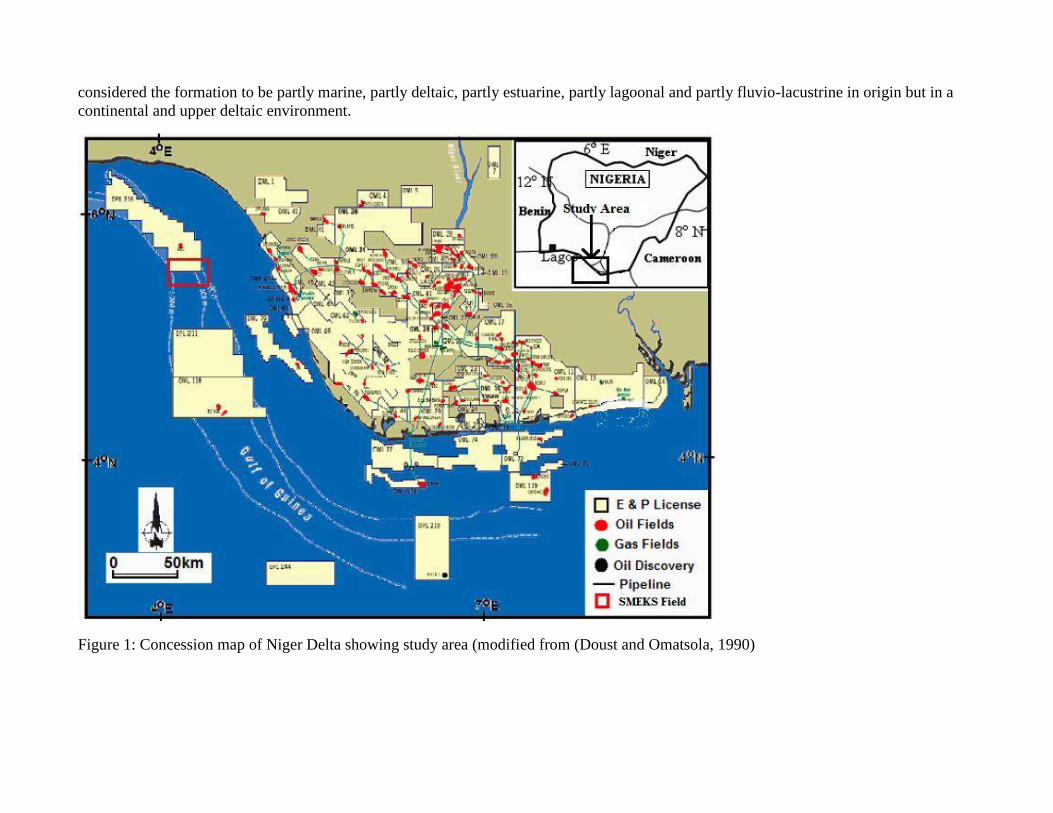
The study area is a field situated in OML-X, belonging to Nigerian Agip Exploration Ltd, offshore western Niger Delta in the Gulf of
Guinea (Figure 1). The map showing location of wells used in this study is shown in Figure 2. It lies in a water depth range of 300-400 m.
The Niger Delta province is said to have a sediment thickness of 12 km at the central portion with an area extent of about 75,000 km2
(Reijers et al., 1997). The source of the sedimentary fill is the Niger-Benue and Cross Rivers with other distributaries prograding into the
Atlantic Ocean. These fills gave rise to the formations found in the basin, which consists of unconsolidated sands and over pressured
shales. While the sands are fluvial to fluvio marine (channels and barrier bars respectively), the shales are fluvial marine or lagoonal.
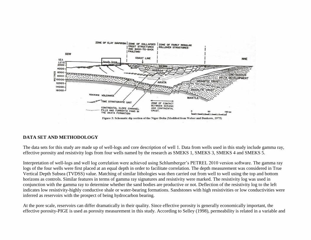
The formations in the Tertiary Niger Delta include the Agbada and Benin Formations to the North with a transition to the Akata Formation
in the deep water portion of the Basin where the Agbada and Benin Formations thin and disappear seaward (Figure 3).
The Akata Formation at the base of the delta is of marine origin and is composed of thick shale sequences (potential source rock), turbidite
sand (potential reservoirs in deep water), and minor amounts of clay and silt. The formation underlies the entire delta, and is typically
overpressured. Turbidity currents likely deposited deep sea fan sands within the upper Akata Formation during development of the delta
(Burke, 1972).
The Agbada Formation which overlies the Akata Formation, consists of unconsolidated to slightly consolidated paralic siliciclastic
sequence of sandy unit with minor shale intercalations of about 4500 m thick (Weber and Daukoru, 1975). There is consistently an upward
increase in the sand content in any given area. In the lower portion, shale and sandstone beds are deposited in equal proportion (50%),
however, the upper section is mostly sand (75%) with minor shale intercalations. Its oldest units of sediments are Eocene in age and
deposition continues to Recent. Channel and basin-floor fan deposits in the Agbada Formation constitutes the main reservoirs of the Niger
Delta.
The Benin Formation marks the upper most unit of the Delta complex and consists mainly of 2000 m thick fresh water-bearing massive
continental sands and gravels which are deposited in the upper deltaic plain environment. The sands are yellowish brown or white in colour
due to the presence of limonite, haematite and feldspars. Brackish water and marine faunas are absent in this formation. Reyment (1965)
considered the formation to be partly marine, partly deltaic, partly estuarine, partly lagoonal and partly fluvio-lacustrine in origin but in a
continental and upper deltaic environment.
Figure 1: Concession map of Niger Delta showing study area (modified from (Doust and Omatsola, 1990)
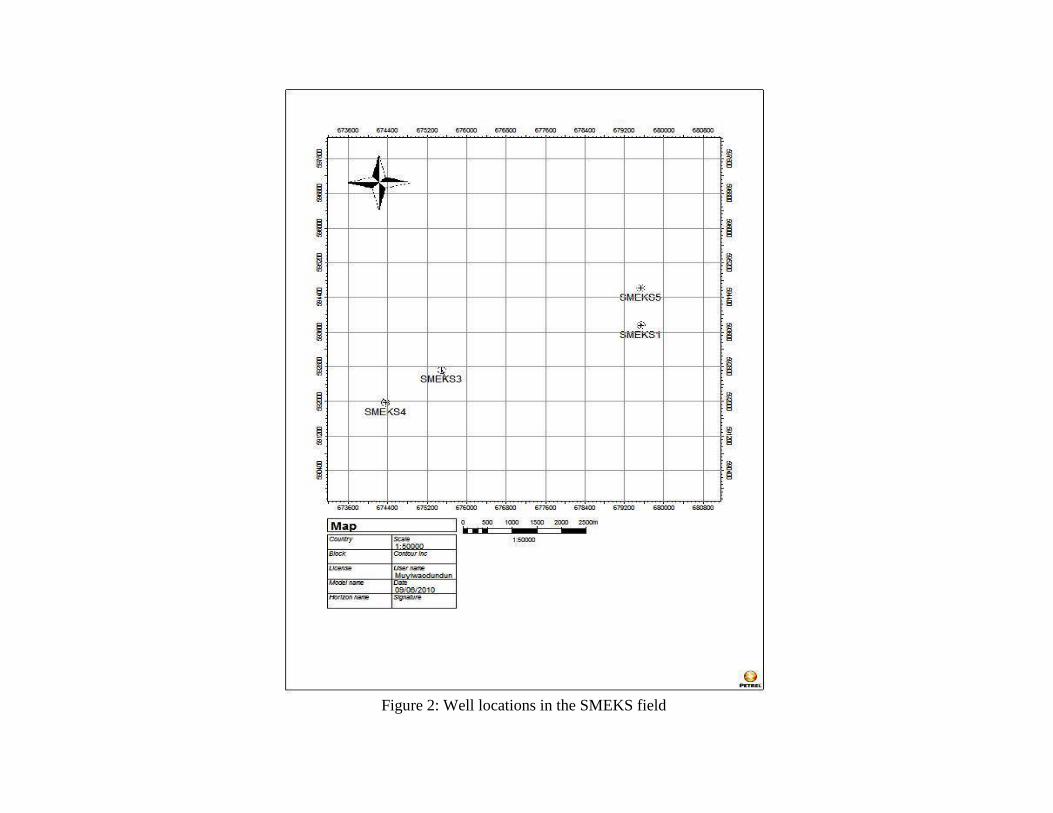
Figure 2: Well locations in the SMEKS field
DATA SET AND METHODOLOGY
The data sets for this study are made up of well-logs and core description of well 1. Data from wells used in this study include gamma ray,
effective porosity and resistivity logs from four wells named by the research as SMEKS 1, SMEKS 3, SMEKS 4 and SMEKS 5.
Interpretation of well-logs and well log correlation were achieved using Schlumberger’s PETREL 2010 version software. The gamma ray
logs of the four wells were first placed at an equal depth in order to facilitate correlation. The depth measurement was considered in True
Vertical Depth Subsea (TVDSS) value. Matching of similar lithologies was then carried out from well to well using the top and bottom
horizons as controls. Similar features in terms of gamma ray signatures and resistivity were marked. The resistivity log was used in
conjunction with the gamma ray to determine whether the sand bodies are productive or not. Deflection of the resistivity log to the left
indicates low resistivity-highly conductive shale or water-bearing formations. Sandstones with high resistivities or low conductivities were
inferred as reservoirs with the prospect of being hydrocarbon bearing.
At the pore scale, reservoirs can differ dramatically in their quality. Since effective porosity is generally economically important, the
effective porosity-PIGE is used as porosity measurement in this study. According to Selley (1998), permeability is related in a variable and
complex way to porosity, pore size, arrangement of pores and pore throats, and grain size. The result of well log analysis – irreducible
water saturation - made available was useful in estimating the permeability. The equation used in estimating the permeability is shown
below;
(Rojstaczer et al., 2008)
Where K is the absolute permeability
Øe is the effective porosity
Sw is the irreducible water saturation
Prediction of depositional environment can be made based on sandstone composition, grain size characteristics, spontaneous potential, and
gamma ray log shapes (Morris and Biggs, 1990). Vail and Wornardt (1991), used the log shapes, resulting from a combination of
spontaneous potential or gamma ray and resistivity to interprete the lithofacies and depositional systems in the Gulf of Mexico. In this
study, prediction of depositional environment was made from the usage of gamma ray log shapes (Fig.4). Stratigraphic modelling
involving creating logs showing facies and depositional environments, was carried out in Petrel, using the log calculator.
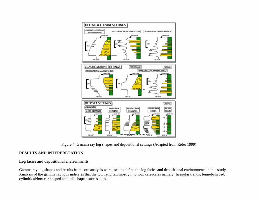
Figure 4: Gamma ray log shapes and depositional settings (Adapted from Rider 1999)
RESULTS AND INTERPRETATION
Log facies and depositional environments
Gamma ray log shapes and results from core analysis were used to define the log facies and depositional environments in this study.
Analysis of the gamma ray logs indicates that the log trend fall mostly into four categories namely; Irregular trends, funnel-shaped,
cylindrical/box car-shaped and bell-shaped successions.
Modified from Shell (1982)
Irregular log trends
The irregular trend abounds in the analysis (Figures 5-9). According to Emery and Myers (1996), the trend has no character, representing
aggradation of shales or silts. In SMEKS 1 (Fig.5) where there is a cored interval, it can be seen that the irregular log trends, when
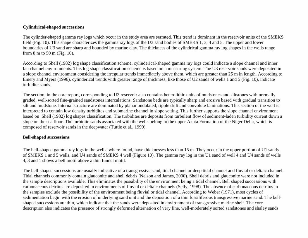
calibrated with core data, indicates the presence of shale and silts. The trend is more prominent in SMEKS 5 well showing from a depth of
1500 m to 1680 m. The irregular shape of gamma ray log in the analysis classifies the log facies as belonging to a basin plain environment.
The environment is characteristically, a blanket of clays and fine silts deposited from suspension, with high lateral continuity and low
lithologic variation. As reported by Coleman and Prior (1980), since deposition is entirely from suspension, parallel laminae are by far the
most common primary structure.
Funnel-shaped successions
The gamma ray log trend of SMEKS 3 (Fig.7), which occur between depths of 1614 and 1620 m, is serrated and funnel-shaped with a
thickness of about 6 m. The trend is usually interpreted to indicate deposition of cleaning upward sediment or an increase in the sand
content of the turbidite bodies, as applied to a deep marine setting.
According to Selley (1998), the environments of shallowing-upward and coarsening successions is divided into three categories namely;
Regressive barrier bars, prograding marine shelf fans and prograding delta or crevasse splays.
The first two environments are commonly deposited with glauconite, shell debris, carbonaceous detritus and mica (Selley, 1998). It is not
likely that these features are present in the well, since the description of the cores from the closest well (SMEKS 1) does not indicate any.
The absence of shell debris, carbonaceous detrirus and glauconite in the core report excludes the possibility of the environment being
regressive barrier bar or prograding marine shelf. The log shape of U4 reservoir (1614-1620 m) of well 3 can then be inferred to indicate a
crevasse splay. This is also supported by the small thickness value of 6 m. One of the main differences between a crevasse splay and a
prograding delta is the depositional scale. According to Chow et al., (2005), the prograding delta is comparatively large. The funnel-shaped
successions in wells 3 and 4, which are less than 8 m, are too thin to be of a prograding marine shelf or a prograding delta (Rider, 1999).
Utilising well log interpretation methods of Shell (1982), facies of prograding marine shelf also occur in wells 3 and 5 but none is a
reservoir sand.
The crevasse splay is a deposit of deltaic sediments formed after the flooding of the bank which leads to fan-shaped sand deposit on the
delta plain (HWU, 2005). Gluyas and Swarbrick (2004) classified the crevasse under the deltaic depositional system. The crevasse splay
sand observed is therefore of deltaic/fluvial setting and this is characteristic of the Agbada Formation where channels and basin floor fan
serve as main reservoirs (Doust and Omatsola, 1990).

Figure 5: Cored interval 1 and depositional environment interpretation of SMEKS1 well.
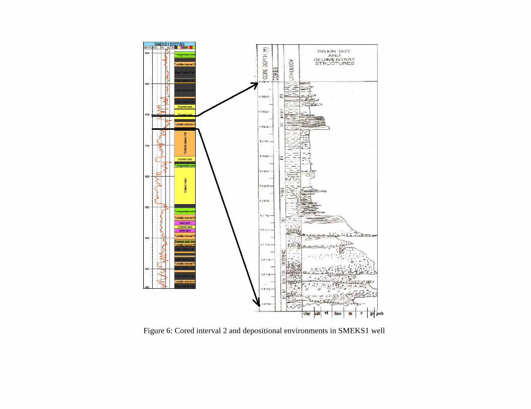
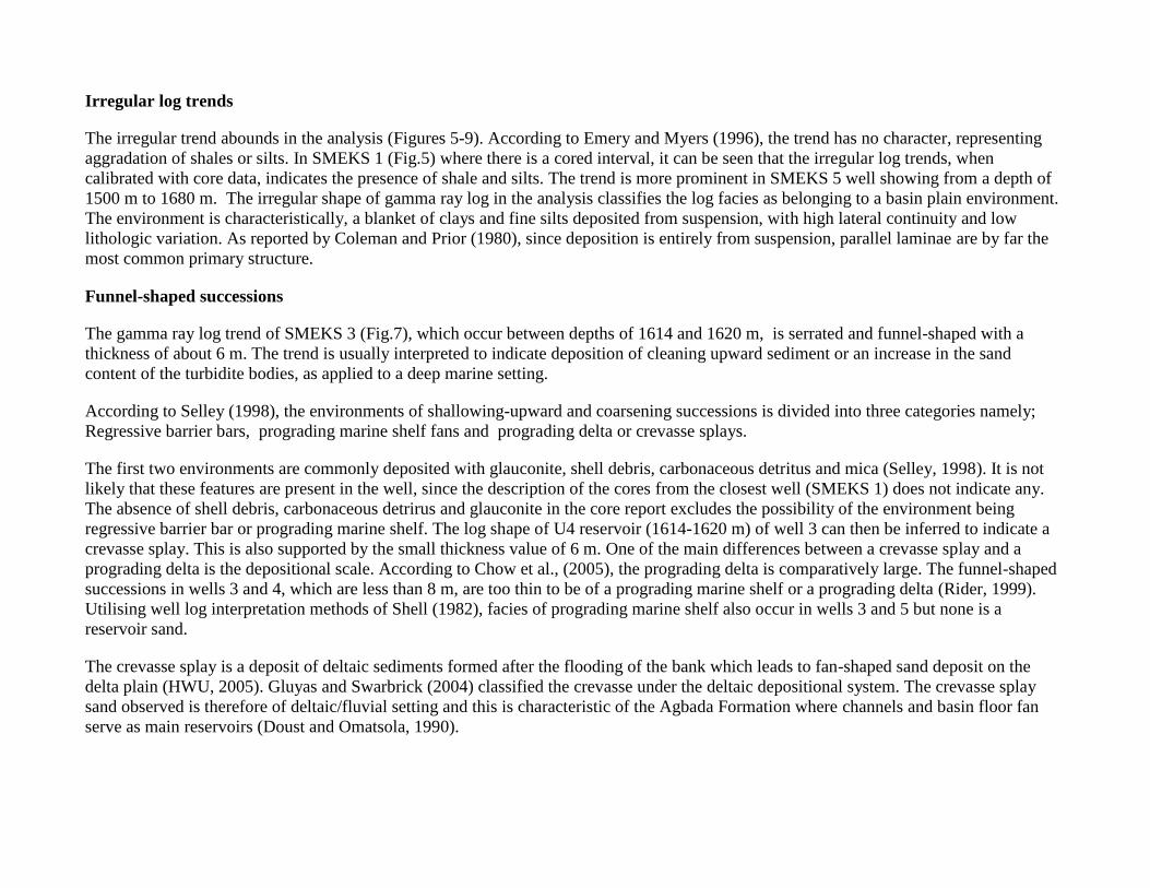
Figure 6: Cored interval 2 and depositional environments in SMEKS1 well
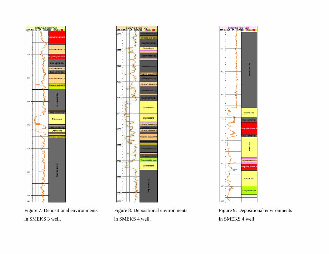
Figure 7: Depositional environments Figure 8: Depositional environments Figure 9: Depositional environments
in SMEKS 3 well. in SMEKS 4 well. in SMEKS 4 well
Cylindrical-shaped successions
The cylinder-shaped gamma ray logs which occur in the study area are serrated. This trend is dominant in the reservoir units of the SMEKS
field (Fig. 10). This shape characterizes the gamma ray logs of the U3 sand bodies of SMEKS 1, 3, 4 and 5. The upper and lower
boundaries of U3 sand are sharp and bounded by marine clay. The thickness of the cylindrical gamma ray log shapes in the wells range
from 8 m to 50 m (Fig. 10).
According to Shell (1982) log shape classification scheme, cylinderical-shaped gamma ray logs could indicate a slope channel and inner
fan channel environments. This log shape classification scheme is based on a measuring system. The U3 reservoir sands were deposited in
a slope channel environment considering the irregular trends immediately above them, which are greater than 25 m in length. According to
Emery and Myers (1996), cylinderical trends with greater range of thickness, like those of U2 sands of wells 1 and 5 (Fig. 10), indicate
turbidite sands.
The section, in the core report, corresponding to U3 reservoir also contains heterolithic units of mudstones and siltstones with normally
graded, well-sorted fine-grained sandstones intercalations. Sandstone beds are typically sharp and erosive based with gradual transition to
silt and mudstone. Internal structure are dominated by planar ondulated, ripple drift and convolute laminations. This section of the well is
interpreted to contain low density turbidites and submarine channel in slope setting. This further supports the slope channel environment
based on Shell (1982) log shapes classification. The turbidites are deposits from turbulent flow of sediment-laden turbidity current down a
slope on the sea floor. The turbidite sands associated with the wells belong to the upper Akata Formation of the Niger Delta, which is
composed of reservoir sands in the deepwater (Tuttle et al., 1999).
Bell-shaped successions
The bell-shaped gamma ray logs in the wells, where found, have thicknesses less than 15 m. They occur in the upper portion of U1 sands
of SMEKS 1 and 5 wells, and U4 sands of SMEKS 4 well (Figure 10). The gamma ray log in the U1 sand of well 4 and U4 sands of wells
4, 3 and 1 shows a bell motif above a thin funnel motif.
The bell-shaped successions are usually indicative of a transgressive sand, tidal channel or deep tidal channel and fluvial or deltaic channel.
Tidal channels commonly contain glauconite and shell debris (Nelson and James, 2000). Shell debris and glauconite were not included in
the sample descriptions available. This eliminates the possibility of the environment being a tidal channel. Bell shaped successions with
carbonaceous detritus are deposited in environments of fluvial or deltaic channels (Selly, 1998). The absence of carbonaceous detritus in
the samples exclude the possibility of the environment being fluvial or tidal channel. According to Weber (1971), most cycles of
sedimentation begin with the erosion of underlying sand unit and the deposition of a thin fossiliferous transgressive marine sand. The bell-
shaped successions are thin, which indicate that the sands were deposited in environment of transgressive marine shelf. The core
description also indicates the presence of strongly deformed alternation of very fine, well-moderately sorted sandstones and shaley sands
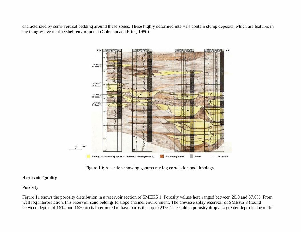
characterized by semi-vertical bedding around these zones. These highly deformed intervals contain slump deposits, which are features in
the trangressive marine shelf environment (Coleman and Prior, 1980).
Figure 10: A section showing gamma ray log correlation and lithology
Reservoir Quality
Porosity
Figure 11 shows the porosity distribution in a reservoir section of SMEKS 1. Porosity values here ranged between 20.0 and 37.0%. From
well log interpretation, this reservoir sand belongs to slope channel environment. The crevasse splay reservoir of SMEKS 3 (found
between depths of 1614 and 1620 m) is interpreted to have porosities up to 21%. The sudden porosity drop at a greater depth is due to the
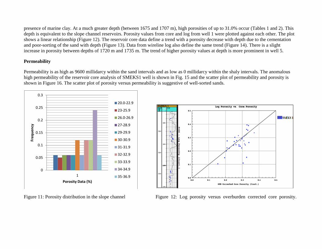
presence of marine clay. At a much greater depth (between 1675 and 1707 m), high porosities of up to 31.0% occur (Tables 1 and 2). This
depth is equivalent to the slope channel reservoirs. Porosity values from core and log from well 1 were plotted against each other. The plot
shows a linear relationship (Figure 12). The reservoir core data define a trend with a porosity decrease with depth due to the cementation
and poor-sorting of the sand with depth (Figure 13). Data from wireline log also define the same trend (Figure 14). There is a slight
increase in porosity between depths of 1720 m and 1735 m. The trend of higher porosity values at depth is more prominent in well 5.
Permeability
Permeability is as high as 9600 millidarcy within the sand intervals and as low as 0 millidarcy within the shaly intervals. The anomalous
high permeability of the reservoir core analysis of SMEKS1 well is shown in Fig. 15 and the scatter plot of permeability and porosity is
shown in Figure 16. The scatter plot of porosity versus permeability is suggestive of well-sorted sands.
Figure 11: Porosity distribution in the slope channel Figure 12: Log porosity versus overburden corrected core porosity.
0
0.05
0.1
0.15
0.2
0.25
0.3
1
Fre
qu
en
cy
Porosity Data (%)
20.0-22.9
23-25.9
26.0-26.9
27-28.9
29-29.9
30-30.9
31-31.9
32-32.9
33-33.9
34-34.9
35-36.9
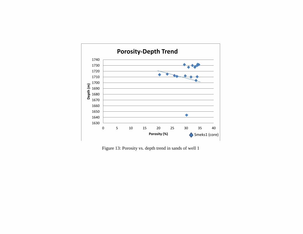
Figure 13: Porosity vs. depth trend in sands of well 1
1630
1640
1650
1660
1670
1680
1690
1700
1710
1720
1730
1740
0 5 10 15 20 25 30 35 40
De
pth
(m
)
Porosity (%)
Porosity-Depth Trend
Smeks1 (core)

Figure 14: Porosity vs. depth trend in sands of SMEKS1 well according to wireline data.
1630
1640
1650
1660
1670
1680
1690
1700
1710
1720
1730
1740
0 10 20 30 40 50
De
pth
(m
)
Porosity(%)
Porosity-Depth Trend
Smeks1(wireline measurement)
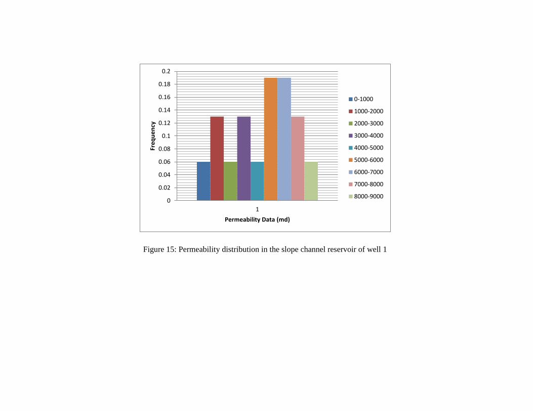
Figure 15: Permeability distribution in the slope channel reservoir of well 1
0
0.02
0.04
0.06
0.08
0.1
0.12
0.14
0.16
0.18
0.2
1
Fre
qu
en
cy
Permeability Data (md)
0-1000
1000-2000
2000-3000
3000-4000
4000-5000
5000-6000
6000-7000
7000-8000
8000-9000
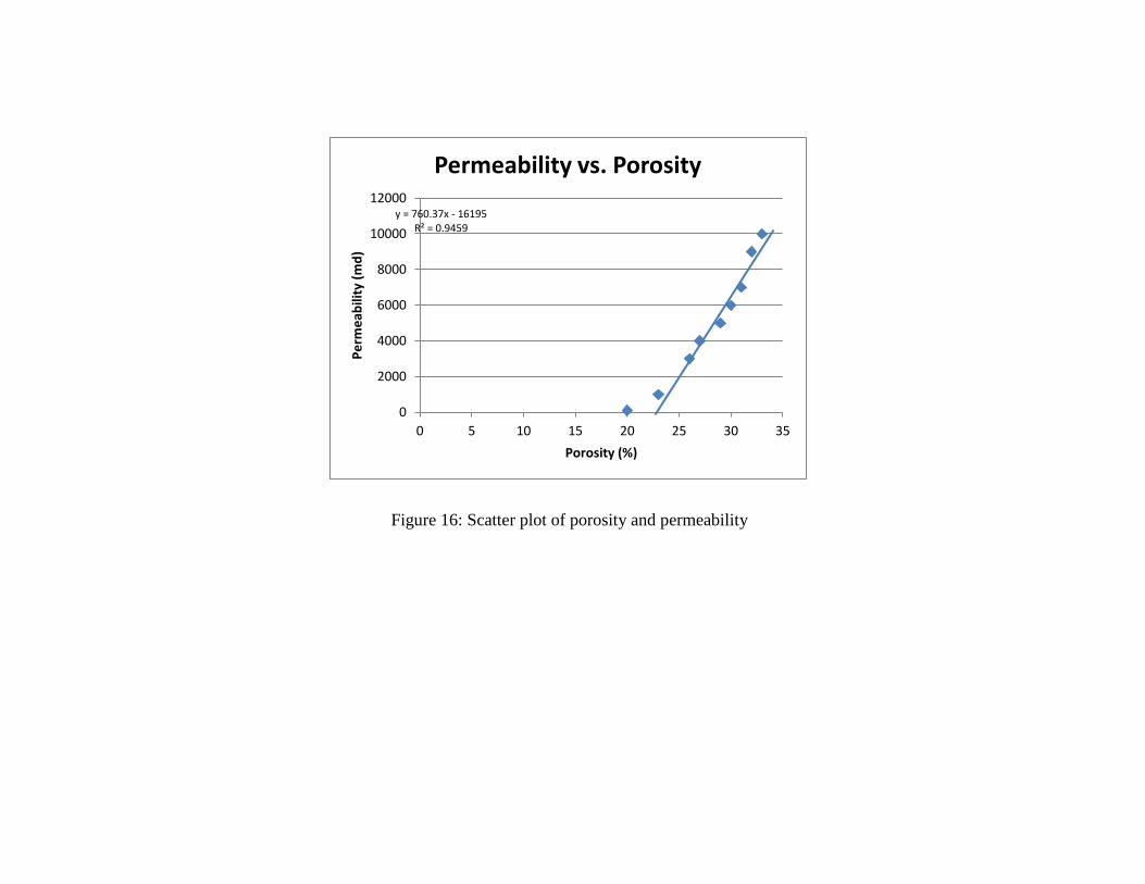
Figure 16: Scatter plot of porosity and permeability
0
2000
4000
6000
8000
10000
12000
0 5 10 15 20 25 30 35
Pe
rme
abili
ty (
md
)
Porosity (%)
Permeability vs. Porosity
y = 760.37x - 16195 R² = 0.9459

Table 1: Porosity and permeability values of reservoir sands in SMEKS1 well
Depth(m) Core Porosity from wireline
log measurements Por.(%) Perm.(md)
1644 30.2 106 0.25
1704 33.6 3840 0.34
1710 31.8 967 0.13
1710.5 34 1010 0.27
1711 26.7 5830 0.31
1712 29.7 3720 0.26
1712.5 25.8 6000 0.24
1714 20.4 6390 0.18
1715 23.2 9080 0.15
1727 30.9 6940 0.23
1727 33.2 9550 0.26
1728 33.3 4970 0.26
1731.5 34.6 6500 0.39
1731.5 29.4 6750 0.38
1732 34.2 8250 0.33
1732.5 37.1 6750 0.35
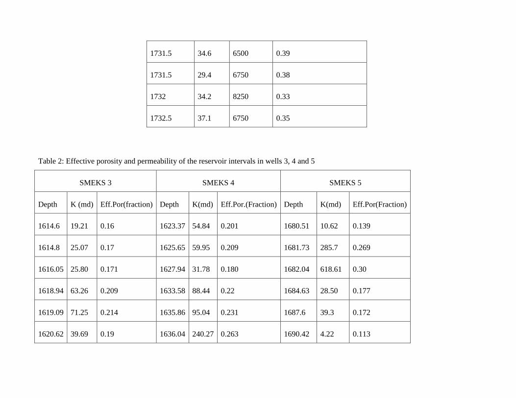
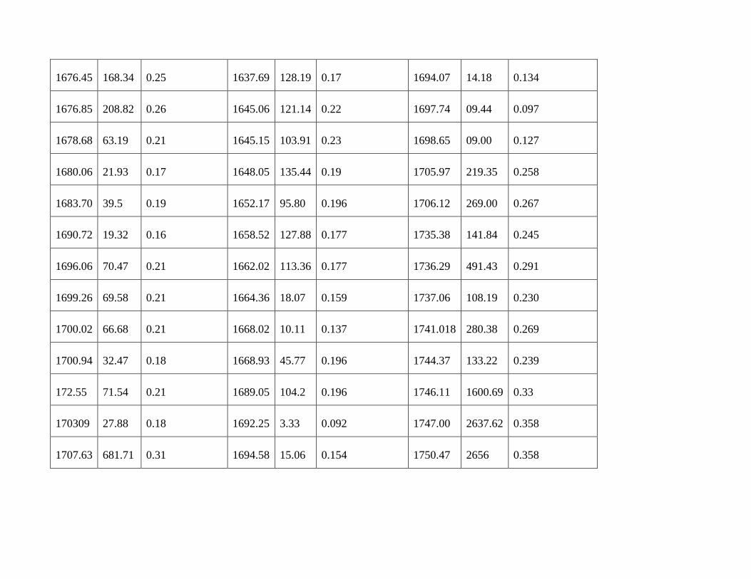
Table 2: Effective porosity and permeability of the reservoir intervals in wells 3, 4 and 5
SMEKS 3 SMEKS 4 SMEKS 5
Depth K (md) Eff.Por(fraction) Depth K(md) Eff.Por.(Fraction) Depth K(md) Eff.Por(Fraction)
1614.6 19.21 0.16 1623.37 54.84 0.201 1680.51 10.62 0.139
1614.8 25.07 0.17 1625.65 59.95 0.209 1681.73 285.7 0.269
1616.05 25.80 0.171 1627.94 31.78 0.180 1682.04 618.61 0.30
1618.94 63.26 0.209 1633.58 88.44 0.22 1684.63 28.50 0.177
1619.09 71.25 0.214 1635.86 95.04 0.231 1687.6 39.3 0.172
1620.62 39.69 0.19 1636.04 240.27 0.263 1690.42 4.22 0.113
1676.45 168.34 0.25 1637.69 128.19 0.17 1694.07 14.18 0.134
1676.85 208.82 0.26 1645.06 121.14 0.22 1697.74 09.44 0.097
1678.68 63.19 0.21 1645.15 103.91 0.23 1698.65 09.00 0.127
1680.06 21.93 0.17 1648.05 135.44 0.19 1705.97 219.35 0.258
1683.70 39.5 0.19 1652.17 95.80 0.196 1706.12 269.00 0.267
1690.72 19.32 0.16 1658.52 127.88 0.177 1735.38 141.84 0.245
1696.06 70.47 0.21 1662.02 113.36 0.177 1736.29 491.43 0.291
1699.26 69.58 0.21 1664.36 18.07 0.159 1737.06 108.19 0.230
1700.02 66.68 0.21 1668.02 10.11 0.137 1741.018 280.38 0.269
1700.94 32.47 0.18 1668.93 45.77 0.196 1744.37 133.22 0.239
172.55 71.54 0.21 1689.05 104.2 0.196 1746.11 1600.69 0.33
170309 27.88 0.18 1692.25 3.33 0.092 1747.00 2637.62 0.358
1707.63 681.71 0.31 1694.58 15.06 0.154 1750.47 2656 0.358
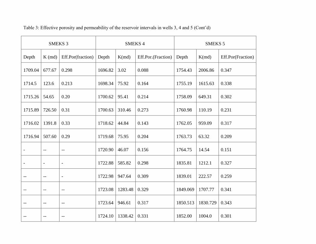
Table 3: Effective porosity and permeability of the reservoir intervals in wells 3, 4 and 5 (Cont’d)
SMEKS 3 SMEKS 4 SMEKS 5
Depth K (md) Eff.Por(fraction) Depth K(md) Eff.Por.(Fraction) Depth K(md) Eff.Por(Fraction)
1709.04 677.67 0.298 1696.82 3.02 0.088 1754.43 2006.86 0.347
1714.5 123.6 0.213 1698.34 75.92 0.164 1755.19 1615.63 0.338
1715.26 54.65 0.20 1700.62 95.41 0.214 1758.09 649.31 0.302
1715.89 726.50 0.31 1700.63 310.46 0.273 1760.98 110.19 0.231
1716.02 1391.8 0.33 1718.62 44.84 0.143 1762.05 959.09 0.317
1716.94 507.60 0.29 1719.68 75.95 0.204 1763.73 63.32 0.209
- -- -- 1720.90 46.07 0.156 1764.75 14.54 0.151
- - - 1722.88 585.82 0.298 1835.81 1212.1 0.327
-- -- - 1722.98 947.64 0.309 1839.01 222.57 0.259
-- -- -- 1723.08 1283.48 0.329 1849.069 1707.77 0.341
-- -- -- 1723.64 946.61 0.317 1850.513 1830.729 0.343
-- -- -- 1724.10 1338.42 0.331 1852.00 1004.0 0.301

-- -- -- 1724.71 2577.45 0.357 1852.57 1041.08 0.321
-- -- -- 1724.86 2903.8 0.362 1853.95 687.66 0.304
-- -- -- -- _ _ 1854.09 706.62 0.306
-- -- -- -- -- -- 1855.92 1035.09 0.321
-- -- -- -- -- -- 1857.15 972.87 0.319
-- -- -- -- -- -- 1857.91 902.30 0.310
-- -- -- -- -- -- 1858.00 1001.61 0.319
CONCLUSIONS
The SMEKS field is a deep offshore field located off the western coast of the Niger delta in the Gulf of Guinea. The combination of core
description data from the cored well and gamma ray log responses was useful in generating a series of log facies. The log facies were used
to describe the reservoir section in the uncored, but logged wells in the field. Four log facies were recognized in the study area. The facies
represents palaeodepositional environments of basin plain, crevasse splay, slope channel and transgressive marine shelf. The crevasse
splays belong to parts of a deltaic system which is characteristic of the Agbada Formation. The transgressive sands belong to the clastic
marine setting while the slope channel and the basin plain belong to the deep sea setting.
The dominant lithologies in the wells are sand, silt and clay. Majority of the sand bodies are those of the slope channel-fills and turbidite
fans. These are marine sand deposits occurring underneath the paralic sandy sediments of the Agbada Formation, that is, the upper Akata
Formation. The sands occur at depths ranging from 1640 m to 1800 m. These sand bodies are 52 m thick or less and are poorly sorted to
well sorted, fine clayey sands with some conglomerate. Some of these sand bodies serve as reservoirs in the deep water. The quality of the
reservoirs was measured as porosity and permeability. Generally, there is a porosity decrease with depth except at depths containing porous
sand which could be as a result of overpressures, limiting significant quartz cementation in these zones.

The challenge encountered in the correlation of the wells, gives an insight on the complex nature of the fault systems in the field. Doust
and Omatsola (1990), stated that the distal delta province is the most structurally complex due to internal gravity tectonics on the modern
continental slope. A limited sand continuity observed across the field is attributed to strict control exerted by the depositional agent, low
sand supply, erosional processes and lateral facies changes.
ACKNOWLEDGEMENTS
The authors would like to thank the management of Nigeria Agip Exploration Limited for the data set used in this study. We are indeed
grateful to Schlumberger Nigeria Limited for the software installation at the workstation of the Department of Geology, University of
Ibadan, Nigeria. The contributions of Mrs. Pauline Ale and Mr. Bankole Aderemi of Schlumberger Nigeria Limited in the provision of
technical assistance are invaluable.
REFERENCES
Burke, K.C. (1972). Longshore drift submarine canyons and submarine fans in the development of the Niger Delta. AAPG Bulletin 56, pp.
1975-1983.
Chow, J. J., Ming.-Ching Li. and Fuh, S. (2005). Geophysical well log study on the paleoenvironment of the hydrocarbon producing zones
in the Erchungchi Formation, Hsinyin, SW Taiwan. TAO, Vol.16, No.3, pp. 531-543.
Coleman, J. M. and Prior, D.B. (1980). Deltaic sand bodies; A 1980 education short course. AAPG Note Series No.14.
Doust, H. and Omatsola, E. (1990). Niger Delta. In; J.D. Edwards and Santogrossi.(Eds.), Divergent/Passive Margins basin. American
Association of Petroleum Geologist Memoir 48. pp. 201-238.
Emery, D. and Myers, K.J. (1996). Sequence Stratigraphy. Blackwell Science Ltd.
Gluyas, J. and Swarbick, R. (2004). Petroleum geoscience. Oxford: Blackwell Publishing Co. p. 40-252
HWU. (2005). Petroleum Geoscience. Heriot Watt Institute of Petroleum Engineering.
Morris, R.L. and Biggs, W.P. (1990). Using log derived values of water saturation and porosity. SPWLA 8th Annual Logging Symposium,
1-26.
Nelson, C. S. and James, N.P. (2000). Marine Cements in Mid-Tertiary cool-water shelf limestones of New Zealand and Southern
Australia. Sediment 47, 609-629.
Porrenga, D. H. (1967). Glauconite and chamosite as depth indicators in the marine environment. Marine Geology 5, 495-501.

Reijers, T. J., Petters, S.W. and Nwajide, C.S. (1997). The Niger Delta. In R. e. Selley, African Basins-Sedimentary Basin of the World 3.
Amsterdam: Elsevier Science. pp. 151-172.
Reyment, R. A. (1965). Aspect of geology of Nigeria. Ibadan: University of Ibadan Press.
Rider, M.H. (1999). Geologic interpretation of well logs. Whittles Publishing Services.
Rojstaczer, Ingbristen, S.E. and Hayb, D.O. (2008). Permeability of continental crust influenced by internal and external forces. Geofluids
8, 128-139.
Selley, R.C. (1998). Elements of Petroleum Geology. Department of Geology, Imperial College, London. pp. 37-145.
Shell. (1982). Well log interpretation: Chapters 11,12 and 13. Shell Houston.
Tuttle, L.W., Charpentier, R.R. and Brownfield, M.E. (1999). The Niger Delta Petroleum System: Niger Delta province, Nigeria,
Cameroon and Equatorial Guinea, Africa. Denver: USGS. Open-File Report 99-50-H.
Vail, P.R. and Wornardt, W. (1991). An integrated approach to exploration and development in the 90s. Well log seismic sequence
stratigraphy analysis. Gulf Coast Association of Geologists XL1, 630-650.
Weber, K. (1971). Sedimentological aspects of oil fields in the Niger Delta. . Geologie en Mijnbouw, volume 50, 559-576.
Weber, K.J. and Daukoru, E.M. (1975). Petroleum geological aspects of the Niger Delta. 9th World Petroleum Congress Proceedings, 209-
221.
Whiteman, A. (1982). Nigeria: Its petroleum geology resources and potential vol.1. London: Grantman and Trontman. P.394
Related Documents