Sensors 2014, 14, 21726-21749; doi:10.3390/s141121726 sensors ISSN 1424-8220 www.mdpi.com/journal/sensors Article Face Recognition System for Set-Top Box-Based Intelligent TV Won Oh Lee, Yeong Gon Kim, Hyung Gil Hong and Kang Ryoung Park * Division of Electronics and Electrical Engineering, Dongguk University, 26 Pil-dong 3-ga, Jung-gu, Seoul 100-715, Korea; E-Mails: [email protected] (W.O.L.); [email protected] (Y.G.K.); [email protected] (H.G.H.) * Author to whom correspondence should be addressed; E-Mail: [email protected]; Tel.: +82-2-2260-3329; Fax: +82-2-2277-8735. External Editors: Gianluca Paravati and Valentina Gatteschi Received: 18 April 2014; in revised form: 4 November 2014 / Accepted: 11 November 2014 / Published: 18 November 2014 Abstract: Despite the prevalence of smart TVs, many consumers continue to use conventional TVs with supplementary set-top boxes (STBs) because of the high cost of smart TVs. However, because the processing power of a STB is quite low, the smart TV functionalities that can be implemented in a STB are very limited. Because of this, negligible research has been conducted regarding face recognition for conventional TVs with supplementary STBs, even though many such studies have been conducted with smart TVs. In terms of camera sensors, previous face recognition systems have used high-resolution cameras, cameras with high magnification zoom lenses, or camera systems with panning and tilting devices that can be used for face recognition from various positions. However, these cameras and devices cannot be used in intelligent TV environments because of limitations related to size and cost, and only small, low cost web-cameras can be used. The resulting face recognition performance is degraded because of the limited resolution and quality levels of the images. Therefore, we propose a new face recognition system for intelligent TVs in order to overcome the limitations associated with low resource set-top box and low cost web-cameras. We implement the face recognition system using a software algorithm that does not require special devices or cameras. Our research has the following four novelties: first, the candidate regions in a viewer’s face are detected in an image captured by a camera connected to the STB via low processing background subtraction and face color filtering; second, the detected candidate regions of face are transmitted to a server that has high processing power in order to detect face OPEN ACCESS

Welcome message from author
This document is posted to help you gain knowledge. Please leave a comment to let me know what you think about it! Share it to your friends and learn new things together.
Transcript
Sensors 2014, 14, 21726-21749; doi:10.3390/s141121726
sensors ISSN 1424-8220
www.mdpi.com/journal/sensors
Article
Face Recognition System for Set-Top Box-Based Intelligent TV
Won Oh Lee, Yeong Gon Kim, Hyung Gil Hong and Kang Ryoung Park *
Division of Electronics and Electrical Engineering, Dongguk University, 26 Pil-dong 3-ga, Jung-gu,
Seoul 100-715, Korea; E-Mails: [email protected] (W.O.L.); [email protected] (Y.G.K.);
[email protected] (H.G.H.)
* Author to whom correspondence should be addressed; E-Mail: [email protected];
Tel.: +82-2-2260-3329; Fax: +82-2-2277-8735.
External Editors: Gianluca Paravati and Valentina Gatteschi
Received: 18 April 2014; in revised form: 4 November 2014 / Accepted: 11 November 2014 /
Published: 18 November 2014
Abstract: Despite the prevalence of smart TVs, many consumers continue to use
conventional TVs with supplementary set-top boxes (STBs) because of the high cost of
smart TVs. However, because the processing power of a STB is quite low, the smart TV
functionalities that can be implemented in a STB are very limited. Because of this,
negligible research has been conducted regarding face recognition for conventional TVs
with supplementary STBs, even though many such studies have been conducted with smart
TVs. In terms of camera sensors, previous face recognition systems have used
high-resolution cameras, cameras with high magnification zoom lenses, or camera systems
with panning and tilting devices that can be used for face recognition from various
positions. However, these cameras and devices cannot be used in intelligent TV
environments because of limitations related to size and cost, and only small, low cost
web-cameras can be used. The resulting face recognition performance is degraded because
of the limited resolution and quality levels of the images. Therefore, we propose a new face
recognition system for intelligent TVs in order to overcome the limitations associated with
low resource set-top box and low cost web-cameras. We implement the face recognition
system using a software algorithm that does not require special devices or cameras. Our
research has the following four novelties: first, the candidate regions in a viewer’s face are
detected in an image captured by a camera connected to the STB via low processing
background subtraction and face color filtering; second, the detected candidate regions of
face are transmitted to a server that has high processing power in order to detect face
OPEN ACCESS
Sensors 2014, 14 21727
regions accurately; third, in-plane rotations of the face regions are compensated based on
similarities between the left and right half sub-regions of the face regions; fourth, various
poses of the viewer’s face region are identified using five templates obtained during the
initial user registration stage and multi-level local binary pattern matching. Experimental
results indicate that the recall; precision; and genuine acceptance rate were about 95.7%;
96.2%; and 90.2%, respectively.
Keywords: set-top box; face recognition; in-plane rotation; multi-level local binary pattern
1. Introduction
In recent times, the broadcasting environment has changed significantly owing to the prevalence of
digital TVs, internet protocol (IP) TVs, and smart TVs that provide a variety of multimedia services
and multiple channels. Consequently, audiences can access their desired amount of multimedia
content. Due to these developments in the broadcasting environment, many broadcasters, advertising
agents, media agents, and audience rating survey companies are increasingly interested in measuring
the viewer’s watching patterns. As a result, considerable research is being focused on interactive
TV [1–3]. Many intelligent TVs include cameras that facilitate face recognition technologies and can
be used to identify viewers and provide personalized services [3–7]. Zuo et al. presented a
consumer-oriented face recognition system called HomeFace. Their system can be embedded in a
smart home environment that includes a smart TV for user identification [3]. It uses skin-color-based,
geometry-based, and neural-network (NN)-based face detectors to detect face regions. In addition, it
uses multi-stage, rejection-based linear discriminant analysis (LDA) to classify faces. However, their
system cannot recognize faces that are in in-plane or out-of-plane rotation states or those that are
captured at low resolutions. In-plane rotation of a face frequently occurs when a viewer watches the
TV while lying on his or her side. An et al., proposed a real-time face analysis system that can detect
and recognize human faces and their expressions using adaptive boosting (Adaboost) LDA
(Ada-LDA), and multi-scale and multi-position local binary pattern matching (MspLBP) [4]. However,
their system cannot analyze faces with in-plane rotation. Lee et al., proposed a smart TV interaction
system that performs face detection and classification based on uniform local binary patterns (ULBPs)
and support vector machines (SVMs). In addition, they use local Gabor binary pattern histogram
sequences (LGBPHS) for face recognition [5,7]. However, their system requires an additional
near-infrared camera with illuminators in order to function properly. Lin et al. introduced a prototype
multi-facial recognition technique aided IPTV system that is called EyeTV. Their system uses an IP
camera to acquire the facial features of users, and a multi-facial recognition technique is employed in
order to recognize the viewer’s identity [6]. It also stores the viewing history of a user’s group
automatically. However, the system does not deal with in-plane rotation of faces or faces in various poses.
We propose a new face recognition system for intelligent TVs equipped with supplementary low
resource set-top boxs (STBs) that overcomes the shortcomings of the previous proposals stated above.
Recognizing the faces of TV viewers is different from face recognition for access control. The in-plane
rotations of faces occur frequently in cases of face recognition in a TV environment because viewers
Sensors 2014, 14 21728
often watch TV while lying on their sides. Therefore, our system compensates for in-plane rotations of
face regions by measuring the similarities between the left and right half sub-regions of the face
regions. In addition, it recognizes faces in various poses based on five templates that are stored during
the enrollment process and multi-level local binary patterns (MLBPs).
The remainder of this paper is organized as follows: we describe the proposed system and the
method in Section 2, present experimental results in Section 3, and summarize and present concluding
remarks in Section 4.
2. Proposed System and Method
2.1. Proposed System Architecture
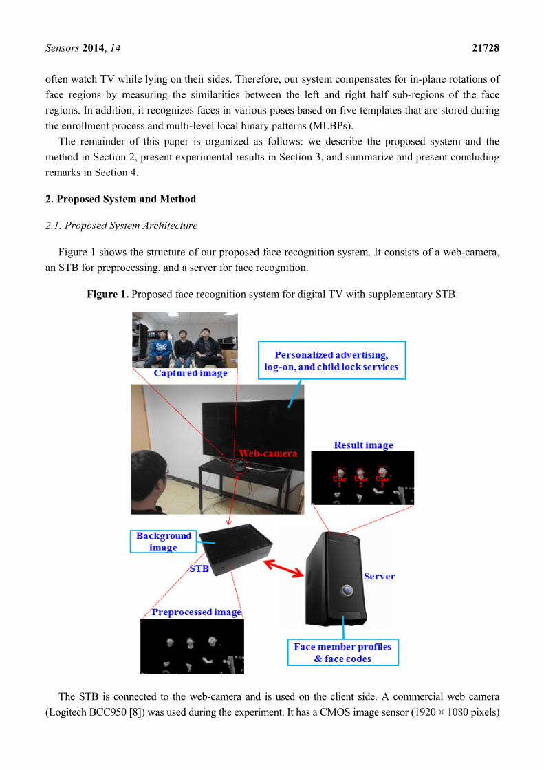
Figure 1 shows the structure of our proposed face recognition system. It consists of a web-camera,
an STB for preprocessing, and a server for face recognition.
Figure 1. Proposed face recognition system for digital TV with supplementary STB.
The STB is connected to the web-camera and is used on the client side. A commercial web camera
(Logitech BCC950 [8]) was used during the experiment. It has a CMOS image sensor (1920 × 1080 pixels)

Sensors 2014, 14 21729
and a diagonal field of view of 78°. The data interface for this camera is USB 2.0. Owing to the
processing power limitations of the STB, we capture images at a resolution of 1280 × 720 pixels.
The background image is also registered for preprocessing on the client side. Our system
automatically recommends that the user update the background image based on measurements of
changes in pixels between the initial background image without any user and the current image. An
updated background image can be saved manually by pressing a button on a remote controller.
However, this procedure of manual update by user is not mandatory but optional to the user (just
recommendation). Even without this procedure of the manual update, our system can detect the area of
user’s face by color filtering in the client side and Adaboost face detector in the server side,
respectively, as shown in Figure 2.
Figure 2. Flowchart of our proposed method: (a) Client part, (b) Server part.
(a) (b)
Then, preprocessing is conducted and the image of a face candidate region is sent to the server via
the communication network. On the server side, family member profiles are pre-registered for face
recognition. The family member profiles and their face codes are enrolled through the STB and the
web-camera during the initial user registration stage. Based on this information, face recognition is
performed using MLBP matching. The experimental results indicate that our proposed system can
provide personalized services such as advertising, log on, and child lock.
2.2. Overview of Proposed Method
Figure 2 shows a flowchart of our proposed method. Figure 2a,b displays the client and server
portions of our proposed method, respectively.
Sensors 2014, 14 21730
A red-green-blue (RGB) color image is captured by a camera connected to the STB in step (1) and
the resulting gray image is obtained. In step (2), the zero pixel values of the gray image are converted
to one in order to discriminate between the non-candidate regions of faces that are assigned as zero
values and the zero pixel values of the input image. In other words, step (2) is performed in order to
distinguish the original zero (black) pixels in the input image from the background areas assigned as
zero (black) pixels through the step (3) of Figure 2. In step (3), the difference image between the
captured image and the pre-saved background image is obtained in order to estimate user candidate
areas. In step (4), morphological operations are performed to remove noise [9]. In step (5), a procedure
is carried out in order to fill in holes in the face region. In step (6), the candidate areas for face regions
are determined using skin color filtering in the face candidate regions obtained in step (5). Then,
morphological operations are performed to remove noise from the face areas and a preprocessed image
is obtained.
In step (8), the preprocessed image is sent to the server over the network. Although the Adaboost
method has been widely used for face detection [10,11], we use the method in Figure 2 for the
following reasons. The proposed face recognition system is implemented in intelligent TV with
supplementary, low resource STB. The processing power of STB is considerably low and therefore,
the Adaboost method can overload the STB. In addition, false detections of face regions by the
Adaboost method can be minimized by discarding non-face candidate regions based on the
preprocessing shown in Figure 2.
On receiving the preprocessed image, the server detects the face regions (step (10)). In order to
detect the face regions when in-plane rotations have occurred, a procedure comprising image rotations
and face detection using the Adaboost method is performed. The Adaboost method is based on a
combination of weak classifiers [10,11]. Based on these steps, multiple face boxes can exist even for a
single face. Therefore, in order to detect and select the correct face box, the gray level difference
histogram (GLDH) method is utilized, as shown in step (11) [12]. The GLDH method is based on the
measurement of the level of similarity between the left and right half sub-regions of the face region. In
step (12), the eye regions are detected based on the Adaboost method. Information about the detected
eye region is utilized in order to reject incorrectly detected face regions, and face normalization is used
for face recognition. The areas of the face region with holes are then filled through interpolation in
step (13), and face recognition is conducted using MLBP.
In order to reduce communication load, one preprocessed image was sent to the server when a user
pressed a button on the remote controller. Therefore, it was not possible to use tracking methods, such
as Kalman and particle filter, that are based on successive frames to detect faces and eyes.
2.3. Preprocessing on the Client Side
Our proposed method is divided into the following two stages: the enrollment stage and the
recognition stage. During the enrollment stage, a user inputs his/her family member code (father,
mother, son, etc.) and a face image is captured by the web-camera. The captured image is then sent to
the server after the preprocessing steps (1)–(8) (Figure 2a). The face region is then detected and facial
codes are enrolled using the MLBP method, as shown in steps (9)–(14) (Figure 2b). Five face images
are captured as the user gazes at the following five positions on the TV screen: top-left, top-right,
Sensors 2014, 14 21731
center, bottom-left, and bottom-right. These images are utilized for face recognition that is robust to
various facial poses. During the recognition stage, face recognition is performed based on facial codes
that were saved during the enrollment stage. In general, many STBs are connected to the remote
server. Thus, preprocessing of the captured image is performed by the clients in order to reduce the
communication load that can arise when sending the original captured images to the server. Figure 3
illustrates the segmentation of the user area of the image—(i.e., steps (1)–(5) in Figure 2).
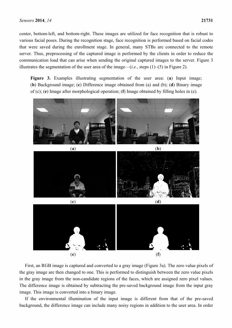
Figure 3. Examples illustrating segmentation of the user area: (a) Input image;
(b) Background image; (c) Difference image obtained from (a) and (b); (d) Binary image
of (c); (e) Image after morphological operation; (f) Image obtained by filling holes in (e).
(a) (b)
(c) (d)
(e) (f)
First, an RGB image is captured and converted to a gray image (Figure 3a). The zero value pixels of
the gray image are then changed to one. This is performed to distinguish between the zero value pixels
in the gray image from the non-candidate regions of the faces, which are assigned zero pixel values.
The difference image is obtained by subtracting the pre-saved background image from the input gray
image. This image is converted into a binary image.
If the environmental illumination of the input image is different from that of the pre-saved
background, the difference image can include many noisy regions in addition to the user area. In order
Sensors 2014, 14 21732
to solve this problem, our system uses the following scheme. If there are significant pixel level
differences between the initial background image without any user and the current image, our system
automatically recommends that the user update the background image. The new background image can
be manually saved by pressing a button on a remote controller.
Then, morphological operations such as erosion and dilation are performed in the binary image in
order to remove noise. The morphological operation in Figure 2 (step (4)) is performed using the
following procedures. First, an erosion operation is performed in order to remove noise and then a
dilation operation is performed in order to remove small holes in face candidate regions. There are two
types of possible errors in the binary image, as shown in Figure 3e. A type 1 error is defined as one in
which the foreground (user area) is incorrectly identified as the background and a type 2 error is the
reverse. The additional procedure to detect accurate face area is performed with the face candidate
regions transmitted to the server. Thus, we designed a filter that reduces the type 1 errors by filling in
holes in the face candidate regions, as defined in Equation (1):
otherwise
mjlibn
if , jib Bml
≥−−
= ∈
,0
),(255
11
),( ),(2
α (1)
here, b(i, j) is the binary image and B is the structuring elements for n × n pixels. We experimentally
determined the values of n and α as 11 and 0.35, respectively. The b(i, j) which is satisfied with the
upper condition of Equation (1) is assigned as 1 and filled as the face candidate pixel. The hole filling
procedure can reduce the holes whose sizes are considerably large to be removed by the morphological
operation. There are many white pixels (correctly defined as face candidate regions) around holes
(incorrectly defined as non-face regions). Based on these characteristics, target pixels are converted
from non-face candidate regions to face candidate ones when the proportion of white pixels is larger
than the α threshold in the n × n mask in Equation (1).
Skin color filtering is then performed. Various color spaces can be used for estimating skin regions.
They include RGB, YCrCb [13], and HSV [14]. In order to reduce the effect of brightness on color, the
color spaces of YCrCb and HSV have been used for the estimation of skin color more than that of
RGB. For our study, we choose the HSV color space for detecting the face color area. In general, the
skin color area is defined in the HSV color space using the parameters in Equation (2) [14]:
1.0V0.35 0.68,S0.20 ,50H0 ≤≤≤≤°≤≤° (2)
Zhang et al. introduced a hue histogram, which they used to analyze 200 pictures of people from the
Mongoloid, Caucasoid, and Negroid ethnic groups [15]. They discovered that skin color pixels are
distributed mainly in the region [0°, 50°], and that there are negligible skin color pixel distributions in
the region [300°, 350°]. Because more accurate face area detections can be performed based on the
face candidate regions that are transmitted to the server, we use a wider range of hue values for color
filtering, as defined in Equation (3), in order to reduce type 1 face detection errors. After the color
filtering is performed based on Equation (3), we perform additional procedures for face detection, face
region verification, eye detection, and face recognition (Figure 2b). Type 2 errors can be reduced by
these additional procedures. However, if type 1 errors occur, they cannot be corrected by these
Sensors 2014, 14 21733
additional procedures. Therefore, we use the less strict conditions in Equation (3) in order to reduce the
type 1 errors, despite the increase in type 2 errors:
°≤≤°°≤≤° 355H300 ,55H0 (3)
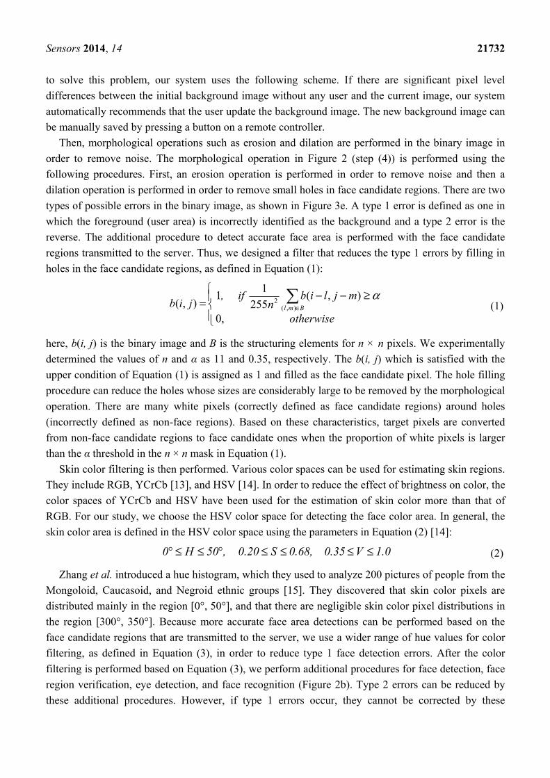
The results of color filtering are shown in Figure 4. Figure 4a,b shows the result after color filtering,
and the resulting image after morphological operations that involve erosion and dilation, respectively.
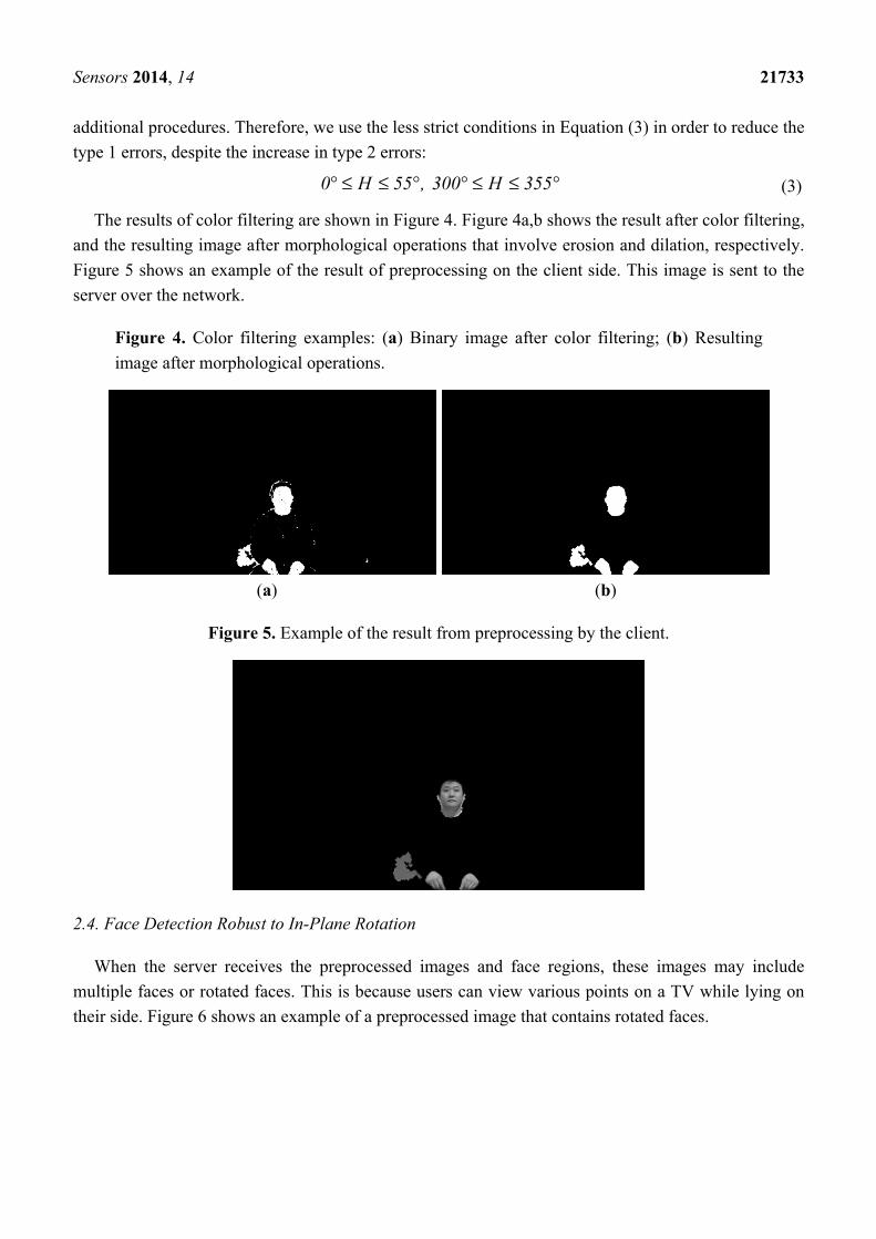
Figure 5 shows an example of the result of preprocessing on the client side. This image is sent to the
server over the network.
Figure 4. Color filtering examples: (a) Binary image after color filtering; (b) Resulting
image after morphological operations.
(a) (b)
Figure 5. Example of the result from preprocessing by the client.
2.4. Face Detection Robust to In-Plane Rotation
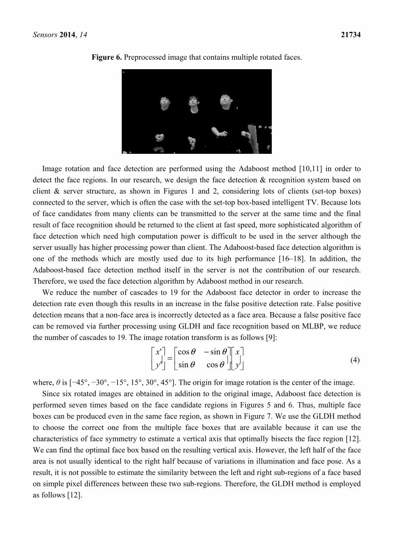
When the server receives the preprocessed images and face regions, these images may include
multiple faces or rotated faces. This is because users can view various points on a TV while lying on
their side. Figure 6 shows an example of a preprocessed image that contains rotated faces.
Sensors 2014, 14 21734
Figure 6. Preprocessed image that contains multiple rotated faces.
Image rotation and face detection are performed using the Adaboost method [10,11] in order to
detect the face regions. In our research, we design the face detection & recognition system based on
client & server structure, as shown in Figures 1 and 2, considering lots of clients (set-top boxes)
connected to the server, which is often the case with the set-top box-based intelligent TV. Because lots
of face candidates from many clients can be transmitted to the server at the same time and the final
result of face recognition should be returned to the client at fast speed, more sophisticated algorithm of
face detection which need high computation power is difficult to be used in the server although the
server usually has higher processing power than client. The Adaboost-based face detection algorithm is
one of the methods which are mostly used due to its high performance [16–18]. In addition, the
Adaboost-based face detection method itself in the server is not the contribution of our research.
Therefore, we used the face detection algorithm by Adaboost method in our research.
We reduce the number of cascades to 19 for the Adaboost face detector in order to increase the
detection rate even though this results in an increase in the false positive detection rate. False positive
detection means that a non-face area is incorrectly detected as a face area. Because a false positive face
can be removed via further processing using GLDH and face recognition based on MLBP, we reduce
the number of cascades to 19. The image rotation transform is as follows [9]:
−=
y
x
y
x
θθθθ
cossin
sincos
'
' (4)
where, θ is [−45°, −30°, −15°, 15°, 30°, 45°]. The origin for image rotation is the center of the image.
Since six rotated images are obtained in addition to the original image, Adaboost face detection is
performed seven times based on the face candidate regions in Figures 5 and 6. Thus, multiple face
boxes can be produced even in the same face region, as shown in Figure 7. We use the GLDH method
to choose the correct one from the multiple face boxes that are available because it can use the
characteristics of face symmetry to estimate a vertical axis that optimally bisects the face region [12].
We can find the optimal face box based on the resulting vertical axis. However, the left half of the face
area is not usually identical to the right half because of variations in illumination and face pose. As a
result, it is not possible to estimate the similarity between the left and right sub-regions of a face based
on simple pixel differences between these two sub-regions. Therefore, the GLDH method is employed
as follows [12].
Sensors 2014, 14 21735
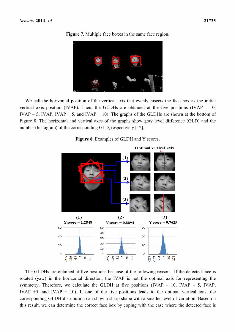
Figure 7. Multiple face boxes in the same face region.
We call the horizontal position of the vertical axis that evenly bisects the face box as the initial
vertical axis position (IVAP). Then, the GLDHs are obtained at the five positions (IVAP – 10,
IVAP – 5, IVAP, IVAP + 5, and IVAP + 10). The graphs of the GLDHs are shown at the bottom of
Figure 8. The horizontal and vertical axes of the graphs show gray level difference (GLD) and the
number (histogram) of the corresponding GLD, respectively [12].
Figure 8. Examples of GLDH and Y scores.
The GLDHs are obtained at five positions because of the following reasons. If the detected face is
rotated (yaw) in the horizontal direction, the IVAP is not the optimal axis for representing the
symmetry. Therefore, we calculate the GLDH at five positions (IVAP – 10, IVAP – 5, IVAP,
IVAP +5, and IVAP + 10). If one of the five positions leads to the optimal vertical axis, the
corresponding GLDH distribution can show a sharp shape with a smaller level of variation. Based on
this result, we can determine the correct face box by coping with the case where the detected face is
Sensors 2014, 14 21736
rotated in the horizontal direction because the severe rotations of faces typically do not occur when
users are watching TV.
We use the Y score defined in Equation (5) to measure the shape of the distribution [12]:
2σMEAN
scoreY = (5)
The MEAN in Equation (5) is the number of pixel pairs whose GLD falls within a specified range
(which we set at ±5) based on the mean of the distribution. The higher the MEAN, the more symmetric
the axis is. The σ parameter represents the standard deviation of the distribution. The higher the Y
score, the more symmetric the face region is based on the axis [12].
As shown in Figure 7, several faces are determined as belonging to the same facial group based on
their distances from each other. That is, the face boxes whose inter-distances between centers are
smaller than the threshold are designated as belonging to the same facial group. Then, the axes that
have larger Y scores than the threshold are chosen from the facial group. Figure 8 shows the GLDH for
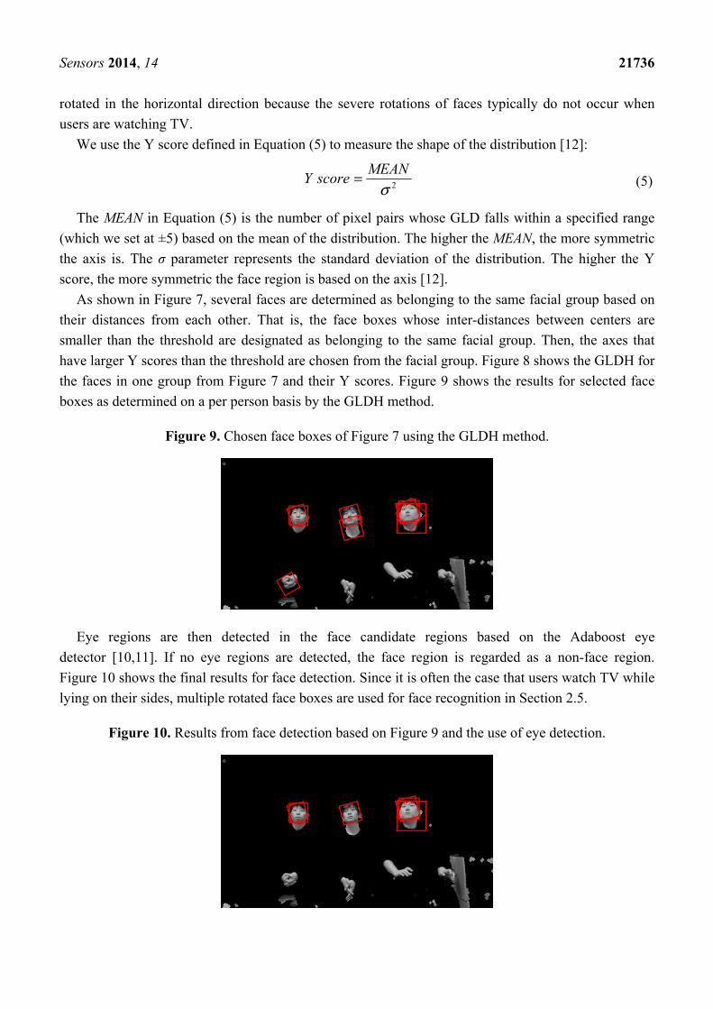
the faces in one group from Figure 7 and their Y scores. Figure 9 shows the results for selected face
boxes as determined on a per person basis by the GLDH method.
Figure 9. Chosen face boxes of Figure 7 using the GLDH method.
Eye regions are then detected in the face candidate regions based on the Adaboost eye
detector [10,11]. If no eye regions are detected, the face region is regarded as a non-face region.
Figure 10 shows the final results for face detection. Since it is often the case that users watch TV while
lying on their sides, multiple rotated face boxes are used for face recognition in Section 2.5.
Figure 10. Results from face detection based on Figure 9 and the use of eye detection.
Sensors 2014, 14 21737
If the multiple face candidates from Figures 7 and 9 are used for face recognition, the processing
time increases considerably. In addition, face recognition errors (false matching) increase because of
the multiple trials during the recognition process.
2.5. Face Recognition Based on MLBP
The detected face regions are used for face recognition. However, the detected face regions can still
contain holes (i.e., incorrectly rejected face pixels) because of image differences and color filtering and
these holes can lead to face recognition errors. In order to rectify this, we interpolate the hole pixels in
the detected face region. If a zero value pixel is found inside the detected region, it is compensated for
by applying a 5 × 5 average mask and by excluding adjacent zero pixels. The interpolated face image
is then normalized based on the two eye positions and used for face recognition based on the MLBP
method. The basic operator for the local binary pattern (LBP) is a simple, yet powerful, texture
descriptor. It is used for texture classification, segmentation, face detection, and face recognition [19].
The basic concept behind the LBP is the assignment of a binary code to each pixel based on a
comparison between the center and its neighboring pixels. In order to acquire large-scale image
structures, the basic LBP was extended to multi-resolution LBP, which is denoted as LBPP, R, as shown
in Figure 11 [20,21]. By extending single-resolution LBP operator to a multi-resolution operator using
the various P and R values, various (local and global) textures can be extracted for face recognition.
The LBPP, R code is obtained using Equation (6) [20,21]:
<≥
=−=−
= 0 ,0
0 ,1)( ,2)(
1
0, x
xxswhereggsLBP
P
p
pcpRP (6)
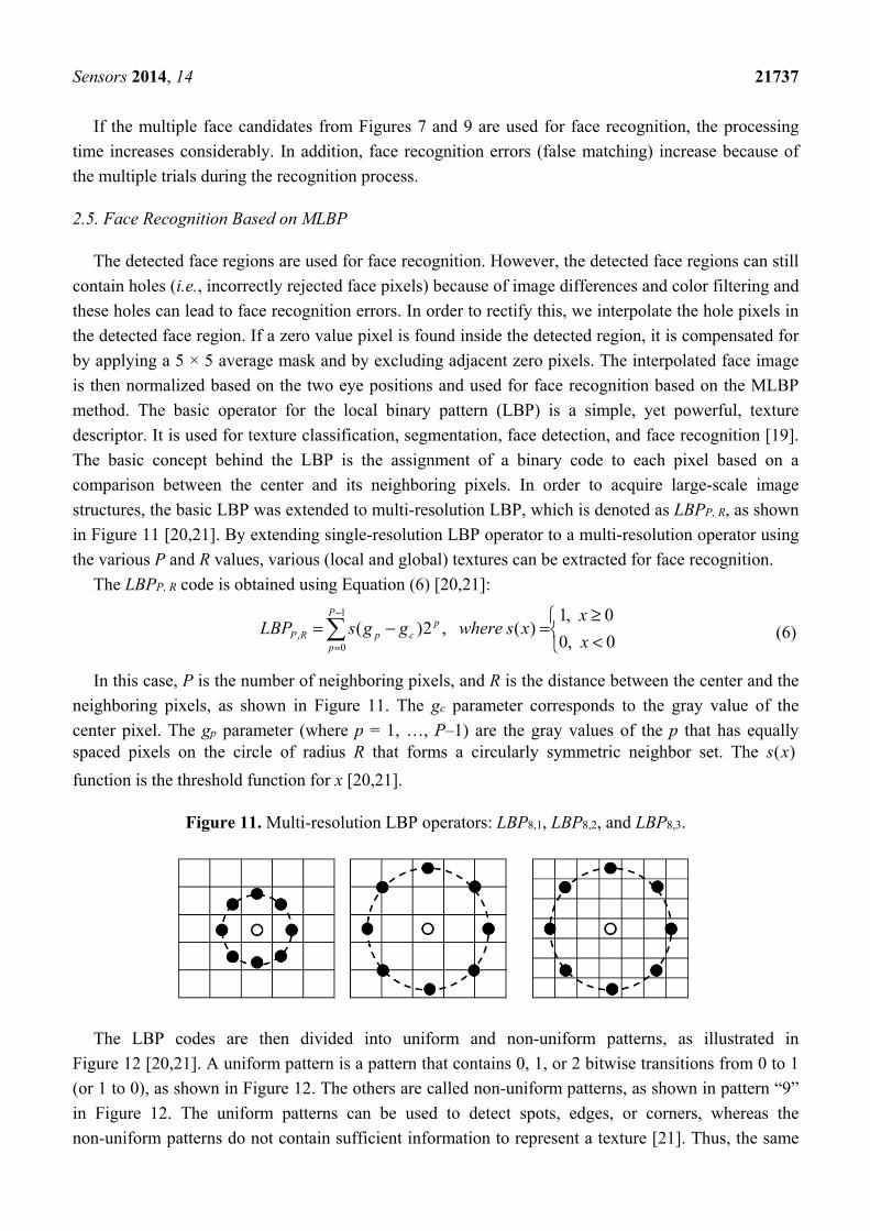
In this case, P is the number of neighboring pixels, and R is the distance between the center and the
neighboring pixels, as shown in Figure 11. The gc parameter corresponds to the gray value of the
center pixel. The gp parameter (where p = 1, …, P–1) are the gray values of the p that has equally spaced pixels on the circle of radius R that forms a circularly symmetric neighbor set. The )(xs
function is the threshold function for x [20,21].
Figure 11. Multi-resolution LBP operators: LBP8,1, LBP8,2, and LBP8,3.
The LBP codes are then divided into uniform and non-uniform patterns, as illustrated in
Figure 12 [20,21]. A uniform pattern is a pattern that contains 0, 1, or 2 bitwise transitions from 0 to 1
(or 1 to 0), as shown in Figure 12. The others are called non-uniform patterns, as shown in pattern “9”
in Figure 12. The uniform patterns can be used to detect spots, edges, or corners, whereas the
non-uniform patterns do not contain sufficient information to represent a texture [21]. Thus, the same
Sensors 2014, 14 21738
code can be assigned to all non-uniform patterns, as shown in pattern “9” in Figure 12. This leads to a
reduction in the number of patterns.
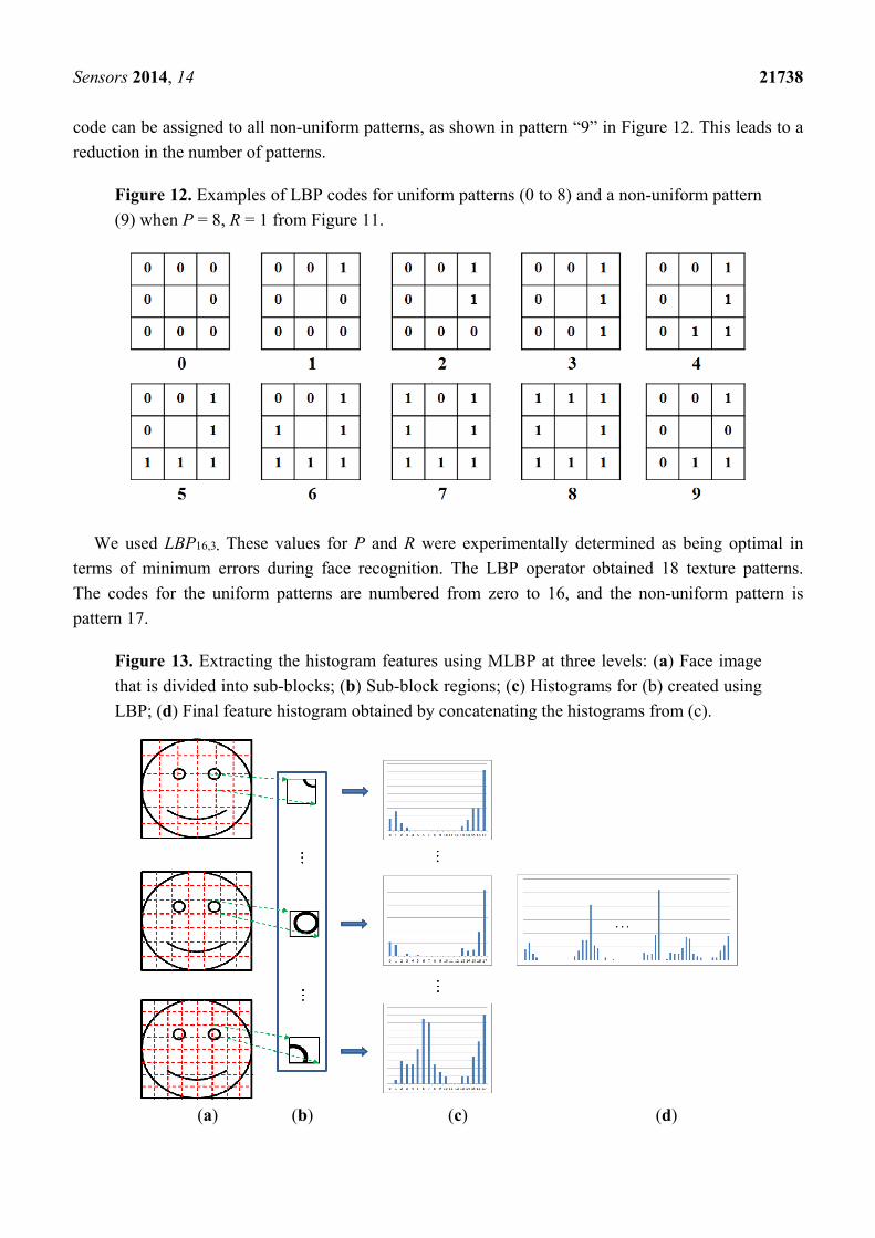
Figure 12. Examples of LBP codes for uniform patterns (0 to 8) and a non-uniform pattern
(9) when P = 8, R = 1 from Figure 11.
We used LBP16,3. These values for P and R were experimentally determined as being optimal in
terms of minimum errors during face recognition. The LBP operator obtained 18 texture patterns.
The codes for the uniform patterns are numbered from zero to 16, and the non-uniform pattern is
pattern 17.
Figure 13. Extracting the histogram features using MLBP at three levels: (a) Face image
that is divided into sub-blocks; (b) Sub-block regions; (c) Histograms for (b) created using
LBP; (d) Final feature histogram obtained by concatenating the histograms from (c).
(a) (b) (c) (d)
Sensors 2014, 14 21739
The final features for face recognition were obtained using the MLBP method [22]. Figure 13
shows the concept behind the MLBP feature extraction technique. The facial image is divided into
sub-blocks, and the LBP histograms are calculated from each block as shown in Figure 13c. Because
the number of texture patterns from the LBP operator is 18, we obtained a histogram with 18
components from each sub-block. In order to represent the histogram features globally and locally, the
sub-blocks for faces are defined at three levels. The upper, middle, and lower faces in Figure 13a are
the first, second, and third levels, respectively. That is, the global features are obtained from the
sub-block for the face area for the first level. Local features are acquired from the sub-blocks for the
third level because each sub-block is defined in the smaller region of the face. All of the histograms for
each block are concatenated in order to form the final feature vector for face recognition, as shown in
Figure 13d. We experimentally determined the optimal number of sub-blocks to be 6 × 6, 7 × 7, and
8 × 8 for the first, second, and third levels, respectively, in terms of minimum errors during
face recognition.
We use the chi-square distance to measure the dissimilarity between enrolled face histogram
features and the dissimilarity from the input image. The chi-square distance is expressed as follows in
Equation (7) [23]:
+−
=i ii
ii
MS
MSMS
22 )(
),(χ (7)
Here, Si is the enrolled histogram and Mi is the calculated histogram for the input image. In order to
cope with faces in various poses (horizontal and vertical rotation), the face histogram feature for the
input image is compared with the five enrolled ones (which were obtained at the initial enrollment
stage) using Equation (7). The input face is then accepted as the enrolled person if the calculated
distance is less than the predetermined threshold. The face region that has smallest chi-square distance
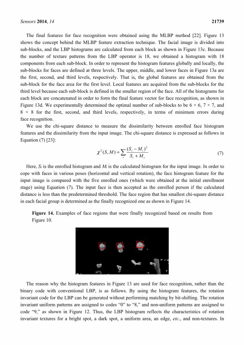
in each facial group is determined as the finally recognized one as shown in Figure 14.
Figure 14. Examples of face regions that were finally recognized based on results from
Figure 10.
The reason why the histogram features in Figure 13 are used for face recognition, rather than the
binary code with conventional LBP, is as follows. By using the histogram features, the rotation
invariant code for the LBP can be generated without performing matching by bit-shifting. The rotation
invariant uniform patterns are assigned to codes “0” to “8,” and non-uniform patterns are assigned to
code “9,” as shown in Figure 12. Thus, the LBP histogram reflects the characteristics of rotation
invariant textures for a bright spot, a dark spot, a uniform area, an edge, etc., and non-textures. In
Sensors 2014, 14 21740
addition, the process for matching based on the binary code from conventional LBP can be affected
more significantly by the misalignment of the regions that are being compared than the process that
depends on histogram features.
3. Experimental Results
We tested our proposed system on an STB (MIPS-based dual core 1.5 GHz, 1 GB DDR3 memory,
and 256/512 MB NAND memory) that was connected to a web-camera and a server with a 3.5 GHz
CPU and 8 GB of RAM. The experimental set-up of TV and the camera in Figure 1 was as follows: the
size of the TV was 60 inch. The distance between the camera lens and the floor was about 79 cm. The
distance between the TV (bottom of TV display) and the floor was about 84 cm.
Fifteen people, divided into five groups, participated in the test. The three persons in each group
carried out five trials using the proposed system. The changes that were made between different trials
included changes to the number of participants (one or three), changes to the seating positions (left,
middle, right), and changes to the Z distances (1.5, 2, 2.5 m). Participants were instructed to look
naturally and randomly at any point on the TV screen without restrictions. A total of 1350 frames
(15 persons × 5 trials × 2 quantities of participants × 3 seating positions × 3 Z distances) were obtained
for measuring the performance of the proposed system. In addition, a total of 75 frames (15 persons × 5
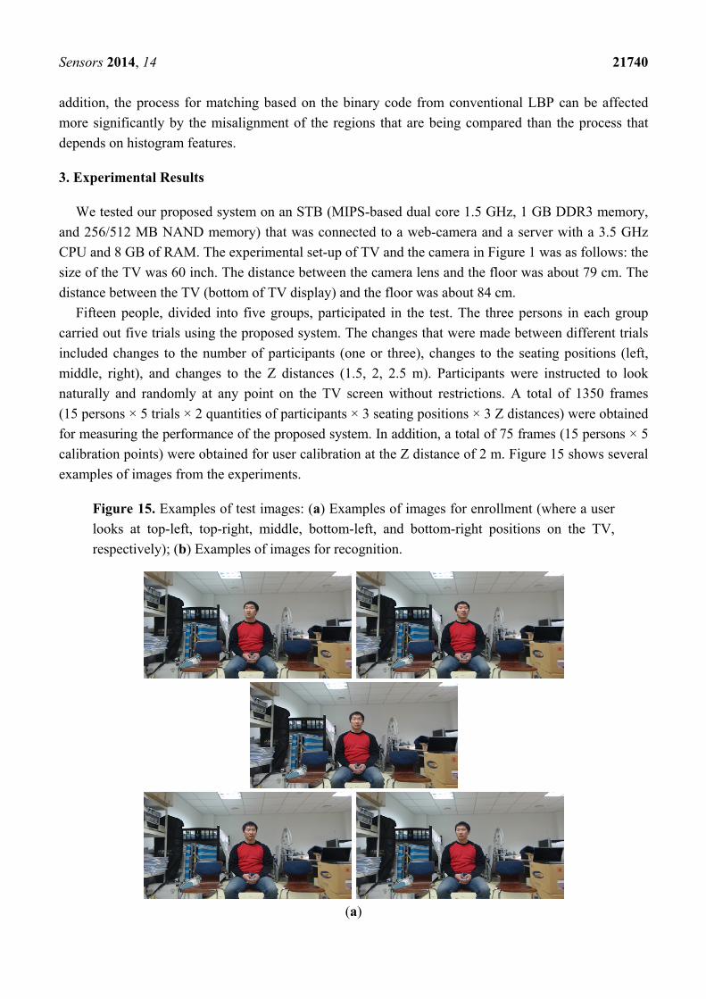
calibration points) were obtained for user calibration at the Z distance of 2 m. Figure 15 shows several
examples of images from the experiments.
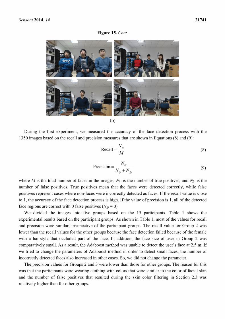
Figure 15. Examples of test images: (a) Examples of images for enrollment (where a user
looks at top-left, top-right, middle, bottom-left, and bottom-right positions on the TV,
respectively); (b) Examples of images for recognition.
(a)
Sensors 2014, 14 21741
Figure 15. Cont.
(b)
During the first experiment, we measured the accuracy of the face detection process with the
1350 images based on the recall and precision measures that are shown in Equations (8) and (9):
M
Ntp=Recall (8)
fptp
tp
NN
N
+=Precision (9)
where M is the total number of faces in the images, Ntp is the number of true positives, and Nfp is the
number of false positives. True positives mean that the faces were detected correctly, while false
positives represent cases where non-faces were incorrectly detected as faces. If the recall value is close
to 1, the accuracy of the face detection process is high. If the value of precision is 1, all of the detected
face regions are correct with 0 false positives (Nfp = 0).
We divided the images into five groups based on the 15 participants. Table 1 shows the
experimental results based on the participant groups. As shown in Table 1, most of the values for recall
and precision were similar, irrespective of the participant groups. The recall value for Group 2 was
lower than the recall values for the other groups because the face detection failed because of the female
with a hairstyle that occluded part of the face. In addition, the face size of user in Group 2 was
comparatively small. As a result, the Adaboost method was unable to detect the user’s face at 2.5 m. If
we tried to change the parameters of Adaboost method in order to detect small faces, the number of
incorrectly detected faces also increased in other cases. So, we did not change the parameter.
The precision values for Groups 2 and 3 were lower than those for other groups. The reason for this
was that the participants were wearing clothing with colors that were similar to the color of facial skin
and the number of false positives that resulted during the skin color filtering in Section 2.3 was
relatively higher than for other groups.

Sensors 2014, 14 21742
Table 1. Experimental Results based on Participant Groups (unit: %).
Group Recall Precision GAR
1 96.85 98.87 90.76 2 89.44 91.15 93.2 3 97.78 92.63 82.89 4 95.74 98.86 96.98 5 98.7 99.26 87.33
Average 95.7 96.15 90.23
In Table 2, we measured the face detection accuracies based on the Z distances of the participants.
The recall values were lower when the participants were at the Z distance of 2.5 m. The reason
for this is that the face sizes became smaller at the far Z distance and the face detection process failed
as a result.
Table 2. Experimental Results based on the Z Distances (unit: %).
Z Distance (m) Recall Precision GAR
1.5 100 96.81 89.11 2 95.78 96.59 92.97
2.5 91.33 96.47 88.61
In Tables 3 and 4, we measured the face detection accuracies based on the seating positions and the
number of participants, respectively. In order to calculate the precision value, Nfp was measured as
shown in Equation (9). False positives occur in the background area, but it is difficult to define the
background region in cases where the results are based on the seating positions, as shown in Table 3.
That is, when three participants are included in same image, it is difficult to separate the three
backgrounds for the participants that are in the left, middle, and right seating positions. Therefore, in
Table 3, the precision value was not measured. As shown in Tables 3 and 4, the face detection
accuracies were similar irrespective of the seating positions and the number of participants.
Table 3. Experimental Results based on Seating Positions (unit: %).
Seating Position Recall GAR
Left 97.11 91.46 Middle 94.22 93.55 Right 95.78 85.64
Table 4. Experimental Results based on the Number of Participants (unit: %).
The Number of Participants
Recall Precision GAR
1 95.7 96.13 90.12 3 95.7 96.13 90.57
During the second experiment, we measured the accuracy of the face recognition process based on
genuine acceptance rate (GAR). By considering the use of the proposed system in a conventional
family, we set the number of enrolled persons at 3. The GAR in Table 1 was calculated using only the
Sensors 2014, 14 21743
face regions that were correctly detected, because the GAR measures the level of performance for face
recognition, rather than detection.
As shown in Tables 1–4, we measured the GAR based on the participant groups, Z distances,
seating positions, and number of participants in the input image. Since the images for enrolled
participants were obtained at the Z distance of 2 m, the GAR at the 2 m was higher in Table 2 than it
was in other cases. As shown in Tables 2–4, we were able to confirm that the accuracy levels from our
system were similar irrespective of the Z distances, seating positions, and the number of participants.
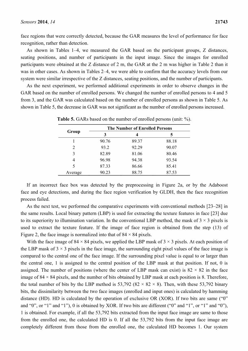
As the next experiment, we performed additional experiments in order to observe changes in the
GAR based on the number of enrolled persons. We changed the number of enrolled persons to 4 and 5
from 3, and the GAR was calculated based on the number of enrolled persons as shown in Table 5. As
shown in Table 5, the decrease in GAR was not significant as the number of enrolled persons increased.
Table 5. GARs based on the number of enrolled persons (unit: %).
Group The Number of Enrolled Persons
3 4 5
1 90.76 89.37 88.18 2 93.2 92.29 90.07 3 82.89 81.06 80.46 4 96.98 94.38 93.54 5 87.33 86.66 85.41
Average 90.23 88.75 87.53
If an incorrect face box was detected by the preprocessing in Figure 2a, or by the Adaboost
face and eye detections, and during the face region verification by GLDH, then the face recognition
process failed.
As the next test, we performed the comparative experiments with conventional methods [23–28] in
the same results. Local binary pattern (LBP) is used for extracting the texture features in face [23] due
to its superiority to illumination variation. In the conventional LBP method, the mask of 3 × 3 pixels is
used to extract the texture feature. If the image of face region is obtained from the step (13) of
Figure 2, the face image is normalized into that of 84 × 84 pixels.
With the face image of 84 × 84 pixels, we applied the LBP mask of 3 × 3 pixels. At each position of
the LBP mask of 3 × 3 pixels in the face image, the surrounding eight pixel values of the face image is
compared to the central one of the face image. If the surrounding pixel value is equal to or larger than
the central one, 1 is assigned to the central position of the LBP mask at that position. If not, 0 is
assigned. The number of positions (where the center of LBP mask can exist) is 82 × 82 in the face
image of 84 × 84 pixels, and the number of bits obtained by LBP mask at each position is 8. Therefore,
the total number of bits by the LBP method is 53,792 (82 × 82 × 8). Then, with these 53,792 binary
bits, the dissimilarity between the two face images (enrolled and input ones) is calculated by hamming
distance (HD). HD is calculated by the operation of exclusive OR (XOR). If two bits are same (“0”
and “0”, or “1” and “1”), 0 is obtained by XOR. If two bits are different (“0” and “1”, or “1” and “0”),
1 is obtained. For example, if all the 53,792 bits extracted from the input face image are same to those
from the enrolled one, the calculated HD is 0. If all the 53,792 bits from the input face image are
completely different from those from the enrolled one, the calculated HD becomes 1. Our system
Sensors 2014, 14 21744
finally selects the user of enrolled face bits (53,792 bits) (whose HD calculated with the input one is
smallest among all the enrolled ones) as a genuine user.
Principal component analysis (PCA) is one of the most widely used method for face recognition by
representing the facial features as global ones of eigen-coefficients based on eigenfaces [24,25].
Non-negative matrix factorization (NMF) is used for part-based representation by using non-negative
values for the basis and coefficients [26]. Local non-negative matrix factorization (LNMF) is the
enhanced method of NMF by making the local features more distinctive [26]. Support vector
machine-discriminant analysis (SVM-DA) is the enhanced method of conventional linear discriminant
analysis (LDA) based on the fusion of SVM and LDA by solving the limitation of LDA which
assumes that all classes have same density function and Gaussian distributions [27]. Modified census
transform (MCT) is the revised method of LBP by using the average value of the 3 × 3 pixels where the
mask is applied instead of the central value of the 3 × 3 pixels [28]. Therefore, the number of bits
obtained by the MCT mask at each position is 9 (as explained before, the number of bits is 8 in case of
the LBP method). Because the number of positions (where the center of MCT mask can exist) is 82 × 82
in the face image of 84 × 84 pixels, the total number of bits by the MCT method is 60,516 (82 × 82 × 9).
Then, with these 60,516 binary bits, the dissimilarity between the two face images (enrolled and input
ones) is calculated by HD, also. Like the LBP method, our system finally selects the user of enrolled
face bits (60,516 bits) (whose HD calculated with the input one is smallest among all the enrolled
ones) as a genuine user. This kind of scheme (selecting the user of enrolled face features (whose
distance calculated with the input one is smallest among all the enrolled ones) as a genuine user) is
also used for other conventional methods of PCA, LNMF, SVM-DA, and our MLBP-based method.
The same data (which were used for the experiments of Table 5) were used for additional
experiments. In detail, we did not apply the conventional methods (LBP, PCA, LNMF, SVM-DA, and
MCT) directly to the input images. Instead, we applied them to the step of face recognition (step (14)
of Figure 2). That is, the same steps (1)~(13) of Figure 2 were used for both our MLBP-based method and
the conventional ones, which means that we used the same face images (which were obtained through the
steps (1)~(13) of Figure 2) for both our method and the conventional ones for the fair comparisons.
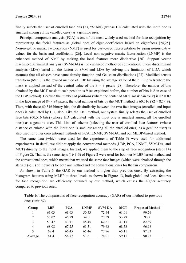
As shown in Table 6, the GAR by our method is higher than previous ones. By extracting the
histogram features using MLBP at three levels as shown in Figure 13, both global and local features
for face recognition are efficiently obtained by our method, which causes the higher accuracy
compared to previous ones.
Table 6. The comparisons of face recognition accuracy (GAR) of our method to previous
ones (unit: %).
Group LBP PCA LNMF SVM-DA MCT Proposed Method
1 63.03 61.03 50.53 72.44 61.01 90.76 2 57.02 45.99 42.1 77.59 53.79 93.2 3 50.47 43.11 48.45 62.61 47.13 82.89 4 68.08 67.25 61.51 79.63 68.53 96.98 5 68.4 66.45 65.46 77.76 65.11 87.33
Average 61.4 56.77 53.61 74.01 59.11 90.23
Sensors 2014, 14 21745
As explained at the beginning part of Section 3, a total of 1350 frames (15 persons × 5 trials × 2
quantities of participants × 3 seating positions × 3 Z distances) were obtained for measuring the
performance of the proposed system. The image size (resolution) of each people is reduced with the
increase of Z distance, and the image data which were obtained at three different Z distances (1.5, 2,
2.5 m) include the effect of the change of image size (resolution), consequently.
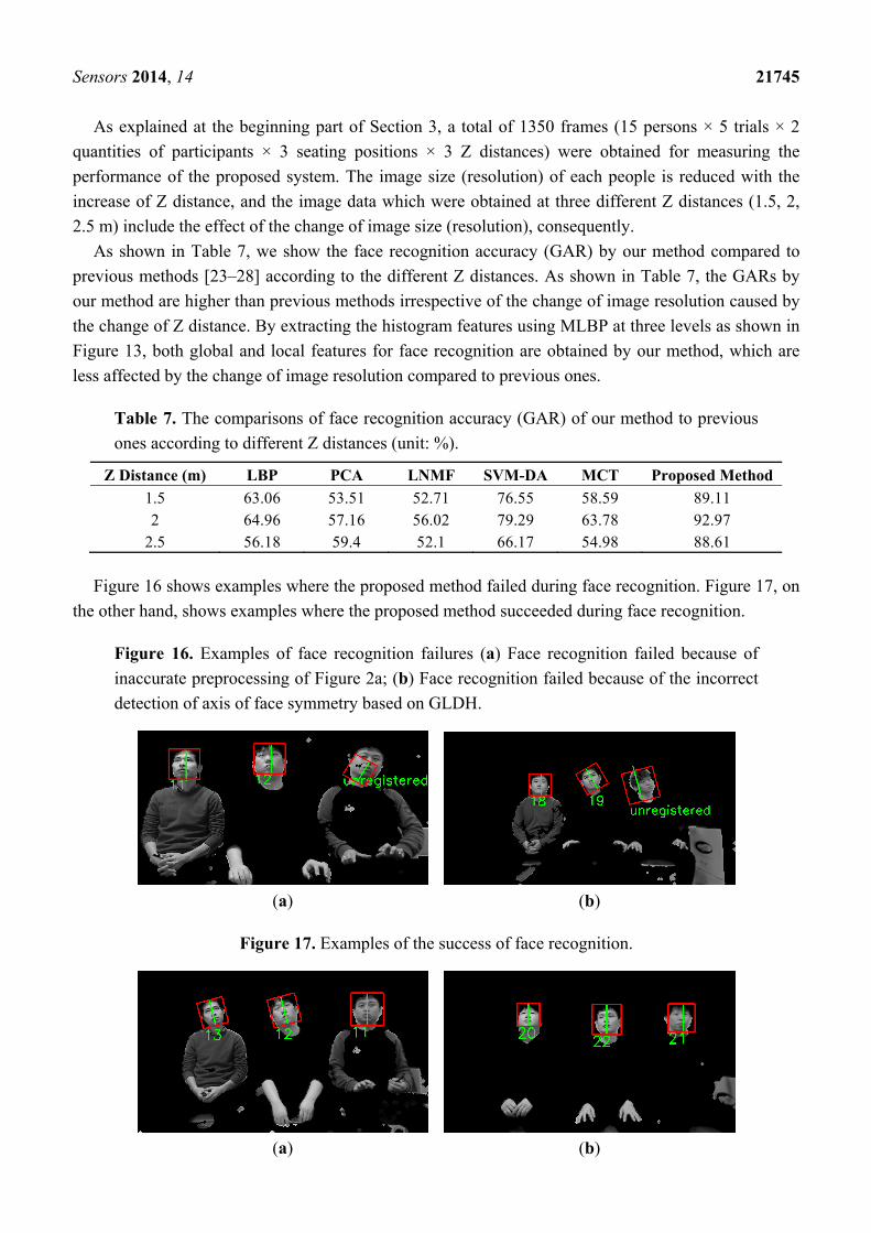
As shown in Table 7, we show the face recognition accuracy (GAR) by our method compared to
previous methods [23–28] according to the different Z distances. As shown in Table 7, the GARs by
our method are higher than previous methods irrespective of the change of image resolution caused by
the change of Z distance. By extracting the histogram features using MLBP at three levels as shown in
Figure 13, both global and local features for face recognition are obtained by our method, which are
less affected by the change of image resolution compared to previous ones.
Table 7. The comparisons of face recognition accuracy (GAR) of our method to previous
ones according to different Z distances (unit: %).
Z Distance (m) LBP PCA LNMF SVM-DA MCT Proposed Method
1.5 63.06 53.51 52.71 76.55 58.59 89.11 2 64.96 57.16 56.02 79.29 63.78 92.97
2.5 56.18 59.4 52.1 66.17 54.98 88.61
Figure 16 shows examples where the proposed method failed during face recognition. Figure 17, on
the other hand, shows examples where the proposed method succeeded during face recognition.
Figure 16. Examples of face recognition failures (a) Face recognition failed because of
inaccurate preprocessing of Figure 2a; (b) Face recognition failed because of the incorrect
detection of axis of face symmetry based on GLDH.
(a) (b)
Figure 17. Examples of the success of face recognition.
(a) (b)
Sensors 2014, 14 21746
Experimental results showed that the processing time per each image is about 185 ms in our system.
Therefore, our system can output result at the speed of about 5 or 6 frames per second. Considering our
applications such as personalized advertizing and program recommendation services, child lock, and
the automatic audience rating survey, our system having the processing speed of about 5 or 6 frames
per second can be sufficiently used for these applications.
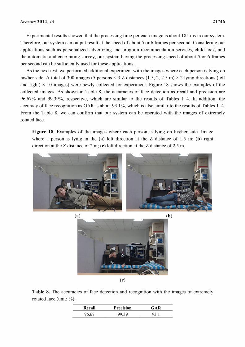
As the next test, we performed additional experiment with the images where each person is lying on
his/her side. A total of 300 images (5 persons × 3 Z distances (1.5, 2, 2.5 m) × 2 lying directions (left
and right) × 10 images) were newly collected for experiment. Figure 18 shows the examples of the
collected images. As shown in Table 8, the accuracies of face detection as recall and precision are
96.67% and 99.39%, respective, which are similar to the results of Tables 1–4. In addition, the
accuracy of face recognition as GAR is about 93.1%, which is also similar to the results of Tables 1–4.
From the Table 8, we can confirm that our system can be operated with the images of extremely
rotated face.
Figure 18. Examples of the images where each person is lying on his/her side. Image
where a person is lying in the (a) left direction at the Z distance of 1.5 m; (b) right
direction at the Z distance of 2 m; (c) left direction at the Z distance of 2.5 m.
(a) (b)
(c)
Table 8. The accuracies of face detection and recognition with the images of extremely
rotated face (unit: %).
Recall Precision GAR
96.67 99.39 93.1
Sensors 2014, 14 21747
4. Conclusions
In this paper, we proposed a new face recognition system for intelligent TVs with supplementary
low resource STBs. Experimental results showed that recall, precision, and GAR values for the system
were about 95.7%, 96.2%, and 90.2%, respectively. In addition, we confirmed that the accuracy of our
system was similar, irrespective of the Z distances, seating positions, and the number of participants.
However, if an incorrect face box was detected during preprocessing, during the Adaboost face and
eye detections, or during the face region verification by GLDH, then face recognition failed.
Based on our face recognition results, we believe that our proposed system can provide personalized
advertising services, log on services, and child lock services in conventional TVs with supplementary
STBs. In a future study, we plan to test our system with a wider variety of STBs, servers, and network
environments, including wired and wireless network environments.
Acknowledgments
This research was supported by Basic Science Research Program through the National Research
Foundation of Korea (NRF) funded by the Ministry of Education (NRF-2012R1A1A2038666).
Author Contributions
Won Oh Lee and Kang Ryoung Park designed the overall system and made the face recognition
algorithm. In addition, they wrote and revised the paper. Yeong Gon Kim and Hyung Gil Hong
implemented the face detection algorithm.
Conflicts of Interest
The authors declare no conflict of interest.
References
1. Isobe, T.; Fujiwara, M.; Kaneta, H.; Uratani, N.; Morita, T. Development and Features of a TV
Navigation System. IEEE Trans. Consum. Electron. 2003, 49, 1035–1042.
2. Zhang, H.; Zheng, S.; Yuan, J. A Personalized TV Guide System Compliant with MHP.
IEEE Trans. Consum. Electron. 2005, 51, 731–737.
3. Zuo, F.; de With, P.H.N. Real-time Embedded Face Recognition for Smart Home. IEEE Trans.
Consum. Electron. 2005, 51, 183–190.
4. An, K.H.; Chung, M.J. Cognitive Face Analysis System for Future Interactive TV. IEEE Trans.
Consum. Electron. 2009, 55, 2271–2279.
5. Lee, S.-H.; Sohn, M.-K.; Kim, D.-J.; Kim, B.; Kim, H. Face Recognition of Near-infrared Images
for Interactive Smart TV. In Proceedings of the 27th Conference on Image and Vision Computing
New Zealand, Dunedin, New Zealand, 26–28 November 2012; pp. 335–339.
6. Lin, K.-H.; Shiue, D.-H.; Chiu, Y.-S.; Tsai, W.-H.; Jang, F.-J.; Chen, J.-S. Design and
Implementation of Face Recognition-aided IPTV Adaptive Group Recommendation System
Based on NLMS Algorithm. In Proceedings of the International Symposium on Communications
and Information Technologies, Gold Coast, Australia, 2–5 October 2012; pp. 626–631.

Sensors 2014, 14 21748
7. Lee, S.-H.; Sohn, M.-K.; Kim, D.-J.; Kim, B.; Kim, H. Smart TV Interaction System Using Face
and Hand Gesture Recognition. In Proceedings of the International Conference on Consumer
Electronics, Las Vegas, NV, USA, 11–14 January 2013; pp. 173–174.
8. Logitech BCC950. Available online: http://www.logitech.com/en-us/support/conferencecam?section
=overview&crid=637&osid=14&bit=64 (accessed on 13 June 2014).
9. Gonzalez, R.C.; Woods, R.E. Digital Image Processing, 2nd ed.; Prentice-Hall: Englewood Cliffs,
NJ, USA, 2002.
10. Viola, P.; Jones, M. Rapid Object Detection Using a Boosted Cascade of Simple Features. In
Proceedings of the Computer Vision and Pattern Recognition, Kauai, HI, USA, 8–14 December
2001; pp. I-511–I-518.
11. Viola, P.; Jones, M.J. Robust Real-time Face Detection. Int. J. Comput. Vis. 2004, 57, 137–154.
12. Chen, X.; Rynn, P.J.; Bowyer, K.W. Fully Automated Facial Symmetry Axis Detection in Frontal
Color Images. In Proceedings of the IEEE Workshop on Automatic Identification Advanced
Technologies, Buffalo, NY, USA, 17–18 October 2005; pp. 106–111.
13. Phung, S.L.; Bouzerdoum, A.; Chai, D. A Novel Skin Color Model in YCbCr Color Space and Its
Application to Human Face Detection. In Proceedings of the International Conference on Image
Processing, Rochester, NY, USA, 22–25 September 2002; pp. I-289–I-292.
14. Wang, Y.; Yuan, B. A Novel Approach for Human Face Detection from Color Images under
Complex Background. Pattern Recognit. 2001, 34, 1983–1992.
15. Zhang, X.-N.; Jiang, J.; Liang, Z.-H.; Liu, C.-L. Skin Color Enhancement Based on Favorite Skin
Color in HSV Color Space. IEEE Trans. Consum. Electron. 2010, 56, 1789–1793.
16. Xu, Y.; Fang, X.; Li, X.; Yang, J.; You, J.; Liu, H.; Teng, S. Data uncertainty in face recognition.
IEEE Trans. Cybern. 2014, 44, 1950–1961.
17. Li, S.Z.; Chu, R.; Liao, S. Zhang, L. Illumination invariant face recognition using near-infrared
images. IEEE Trans. Pattern Anal. Mach. Intell. 2007, 29, 627–639.
18. Bhatt, H.S.; Singh, R.; Vatsa, M. On recognizing faces in videos using clustering-based re-ranking
and fusion. IEEE Trans. Inf. Forensic Secur. 2014, 9, 1056–1068.
19. Ojala, T.; Pietikäinen, M.; Harwood, D. A Comparative Study of Texture Measures with
Classification Based on Feature Distributions. Pattern Recognit. 1996, 29, 51–59.
20. Ojala, T.; Pietikäinen, M.; Mäenpää, T. Multiresolution Gray-scale and Rotation Invariant
Texture Classification with Local Binary Patterns. IEEE Trans. Pattern Anal. Mach. Intell. 2002,
24, 971–987.
21. Choi, S.E.; Lee, Y.J.; Lee, S.J.; Park, K.R.; Kim, J. Age Estimation Using a Hierarchical
Classifier Based on Global and Local Facial Features. Pattern Recognit. 2011, 44, 1262–1281.
22. Happy, S.L.; Georage, A.; Routray, A. A Real Time Facial Expression Classification System
Using Local Binary Patterns. In Proceedings of the 4th International Conference on Intelligent
Human Computer interaction, Kharagpur, India, 27–29 December 2012; pp. 1–5.
23. Ahonen, T.; Hadid, A.; Pietikäinen, M. Face Recognition with Local Binary Patterns.
In Proceeding of the 8th European Conference on Computer Vision, Prague, Czech Republic,
11–14 May 2004; pp. 469–481.
24. Belhumeur, P.N.; Hespanha, J.P.; Kriegman, D.J. Eigenfaces vs. fisherfaces: Recognition using
class specific linear projection. IEEE Trans. Pattern Anal. Mach. Intell. 1997, 19, 711–720.

Sensors 2014, 14 21749
25. Turk, M.; Pentland, A. Eigenfaces for recognition. J. Cogn. Neurosci. 1991, 3, 71–86.
26. Li, S.Z.; Hou, X.W.; Zhang, H.J.; Cheng, Q.S. Learning Spatially Localized, Parts-based
Representation. In Proceedings of the IEEE Conference on Computer Vision and Pattern
Recognition, Kauai, HI, USA, 8–14 December 2001; pp. 207–212.
27. Kim, S.-K.; Park, Y.J.; Toh, K.-A.; Lee, S. SVM-based feature extraction for face recognition.
Pattern Recognit. 2010, 43, 2871–2881.
28. Froba, B.; Ernst, A. Face Detection with the Modified Census Transform. In Proceedings of the
IEEE International Conference on Automatic Face and Gesture Recognition, Seoul, Korea, 17–19
May 2004; pp. 91–96.
© 2014 by the authors; licensee MDPI, Basel, Switzerland. This article is an open access article
distributed under the terms and conditions of the Creative Commons Attribution license
(http://creativecommons.org/licenses/by/4.0/).
Related Documents