ICEBT 2010 Face Recognition Based on Ridgelet Transforms Satyajit Kautkar a , Rahulkumar Koche b , Tushar Keskar c , Aniket Pande d , Milind Rane e , Gary A. Atkinson a a Machine Vision Laboratory, University of West England, Bristol. BS16 1QY. b Portland State University, PO Box 751, Portland, Oregon, USA. c Tata Communications, Chennai, India. d Infosys Technologies, Hydrabad, India. e Department of Electronics, VIT, Pune, 411 037, India. Abstract This paper relates to a face recognition and verification technique based on ridgelet transforms. Our proposed method first uses the ridgelet transform of the face image for feature extraction. This involves first applying a sequen- tial combination of radon and wavelet transforms to both the training and test images. The result is then decomposed into a set of feature vectors. The Euclidean distance between training and test feature vectors is finally used for the actual recognition. Before applying any transform on the training image, we normalize the image using a segmen- tation process based on the YCbCr colour model. This essentially detects the largest region of skin in the image. Experimental results using Yale, AT&T, faces94, faces96 and Indian databases show the superiority of the proposed method with some of the existing popular algorithms. Keywords: Face recognition, ridgelet transform, normalization 1. Introduction Computer vision has gained progressively more importance in day-to-day life during the last few years as the range of applications has been steadily increasing. Face recognition by a computer system is one of the most promising and potentially widespread areas in the field [1]. Biometric recognition or biometrics is the technique in which the identity of the person is verified using either tangible or abstract features of the person such as their face, fingerprints, voice, iris etc. This paper presents a detailed set of experiments and analysis on a new technique of face recognition based on the ridgelet transform. The development of face recognition systems started in early 1960s [2]. Since then, a wide variety of algorithms such as Principle Component Analysis (PCA) and Linear Discriminant Analysis (LDA) have been used, modified and tested consistently. Kirby and Sirovich developed a PCA-based face recognition technique in which images are projected into Eigenspace to calculate the Eigenvectors of faces [3]. Later, LDA or Fisher faces was developed, which used Fisher discriminants to classify different feature vectors [4]. Unfortunately, LDA suffers from the small sample problem and so is less effective if only a small training set is available [5, 6]. Liu and Wechsler used Independent Component Analysis (ICA) of Gabor features with the observation that Gabor-transformed face images exhibit strong characteristics of spatial locality, scale, and orientation selectivity [7]. They also use PCA to reduce the dimensionality Email address: [email protected] (Satyajit Kautkar) c ⃝ 2010 Published by Elsevier Ltd Procedia Computer Science 2 (2010) 35–43 www.elsevier.com/locate/procedia 1877-0509 c ⃝ 2010 Published by Elsevier Ltd doi:10.1016/j.procs.2010.11.006

Welcome message from author
This document is posted to help you gain knowledge. Please leave a comment to let me know what you think about it! Share it to your friends and learn new things together.
Transcript
Procedia Computer Science 00 (2010) 1–9
Procedia ComputerScience
ICEBT 2010
Face Recognition Based on Ridgelet Transforms
Satyajit Kautkara, Rahulkumar Kocheb, Tushar Keskarc, Aniket Panded, Milind Ranee, Gary A. Atkinsona
aMachine Vision Laboratory, University of West England, Bristol. BS16 1QY.bPortland State University, PO Box 751, Portland, Oregon, USA.
cTata Communications, Chennai, India.dInfosys Technologies, Hydrabad, India.
eDepartment of Electronics, VIT, Pune, 411 037, India.
Abstract
This paper relates to a face recognition and verification technique based on ridgelet transforms. Our proposedmethod first uses the ridgelet transform of the face image for feature extraction. This involves first applying a sequen-tial combination of radon and wavelet transforms to both the training and test images. The result is then decomposedinto a set of feature vectors. The Euclidean distance between training and test feature vectors is finally used for theactual recognition. Before applying any transform on the training image, we normalize the image using a segmen-tation process based on the YCbCr colour model. This essentially detects the largest region of skin in the image.Experimental results using Yale, AT&T, faces94, faces96 and Indian databases show the superiority of the proposedmethod with some of the existing popular algorithms.
Keywords: Face recognition, ridgelet transform, normalization
1. Introduction
Computer vision has gained progressively more importance in day-to-day life during the last few years as the rangeof applications has been steadily increasing. Face recognition by a computer system is one of the most promising andpotentially widespread areas in the field [1]. Biometric recognition or biometrics is the technique in which the identityof the person is verified using either tangible or abstract features of the person such as their face, fingerprints, voice,iris etc. This paper presents a detailed set of experiments and analysis on a new technique of face recognition basedon the ridgelet transform.
The development of face recognition systems started in early 1960s [2]. Since then, a wide variety of algorithmssuch as Principle Component Analysis (PCA) and Linear Discriminant Analysis (LDA) have been used, modifiedand tested consistently. Kirby and Sirovich developed a PCA-based face recognition technique in which images areprojected into Eigenspace to calculate the Eigenvectors of faces [3]. Later, LDA or Fisher faces was developed, whichused Fisher discriminants to classify different feature vectors [4]. Unfortunately, LDA suffers from the small sampleproblem and so is less effective if only a small training set is available [5, 6]. Liu and Wechsler used IndependentComponent Analysis (ICA) of Gabor features with the observation that Gabor-transformed face images exhibit strongcharacteristics of spatial locality, scale, and orientation selectivity [7]. They also use PCA to reduce the dimensionality
Email address: [email protected] (Satyajit Kautkar)
c⃝ 2010 Published by Elsevier Ltd
Procedia Computer Science 2 (2010) 35–43
www.elsevier.com/locate/procedia
1877-0509 c⃝ 2010 Published by Elsevier Ltddoi:10.1016/j.procs.2010.11.006
S. Kautkar et al. / Procedia Computer Science 00 (2010) 1–9 2
of the feature vectors. Jadhav and Holambe used a face recognition technique based on Radon and wavelet transforms[8]. In this technique, the directional features of the facial images are calculated in different orientations using theRadon transform which enhances low frequency components in that image. Then, a wavelet transform is applied inRadon space which produces multi-resolution facial image.
Do and Vetterli proposed the Finite Ridgelet Transform (FRIT) to overcome the periodization effect of the finiteRadon transform (FRAT) [9]. They have also showed by numerical analysis that FRIT performs better than wavelettransforms in approximating and denoising images with straight edges. On the other hand, FRIT is only suitable forimages of prime-pixels length, which limits its applications in image processing. Jun et al. proposed an algorithmwhich digitally implements ridgelet transforms suitable for images of dyadic length [10]. Carri et al. presented a 3Dridgelet transform based on discrete analytical 3D lines or the 3D Discrete Analytical ridgelet Transform (DART)[11]. This technique uses a Fourier-based strategy which results in fast perfect backprojection. Chen et al. presented anovel descriptor for feature extraction by using a combination of ridgelets and Fourier transforms [12]. The descriptoris very robust to Gaussian noise and can be used efficiently for pattern recognition.
Some remaining challenges in the field are as follows:
• Facial Expressions: Facial expressions while smiling or frowning may affect the recognition system.
• Size of images: Differences in the image dimensions and cropping regions can be detrimental to a system’sperformance.
• Illumination: For images captured in varying lightning conditions, it is very hard for the system to classify theimages.
• Rotation or pose variance: Rotation of faces within the images greatly affects the system performance.
The detrimental impacts of these problems may be reduced by normalizing the image before the processing. Wedescribe our novel normalization procedure in the next section of the paper. We then present some background theoryon ridgelet transforms before furnishing the details of our method. A detailed set of results and conclusions are thenpresented in sections 5 and 6 of the paper.
2. Normalization
Normalization is a required pre-processing step for most face recognition techniques. In normalization, the imageis transformed into a standard form which is free from any geometric or photometric distortions. In this paper, thenormalization procedure is applied to all training and testing images before the actual recognition takes place.
Our method first extracts the facial image using the YCbCr colour space associated with the image. Y is theluminance component, while Cb and Cr are blue and red component of the image pixel respectively. The methodessentially uses the Cr component to extract the region of the image likely to correspond to skin. The largest suchregion is assumed to be the face and is used to crop the image. In summary, the procedure is as follows:
1. Convert the RGB image into YCbCr colour space.2. Segment the image, assuming that pixels having value of Cr greater than a fixed threshold are skin pixels.3. Convert the image into binary image, where skin pixels are foreground and non-skin pixels become background.
This operation generates a number of foreground areas, of which the largest area is assumed to be the face.4. The foreground areas that are not part of the face are reclassified to background.5. A bounding box is created about the face part and is cropped from the rest of the image.6. The cropped image is rescaled to match the dimensions of the other faces in the database, ready for use in
training and testing.
Although this method is rather simplistic, it does allow for a more rapid normalization than most existing approachesand can be improved further by incorporating eye/nose detection into the cropping phase.
36 S. Kautkar et al. / Procedia Computer Science 2 (2010) 35–43
S. Kautkar et al. / Procedia Computer Science 00 (2010) 1–9 3
3. Ridgelet Transforms
In many image processing tasks, a sparse representation of an image is used in order to compact the image into asmall number of samples. Wavelets are a good example of sparse geometrical image representation. But regardlessof the success of the wavelets, they exhibit strong limitations in terms of efficiency when applied in more than onedimension. Wavelets show good performance for piecewise smooth functions in one dimension, but fail to efficientlyrepresent objects with highly anisotropic elements such as lines or curvilinear structures (e.g. edges). The reason isthat wavelets are non-geometrical and do not exploit the regularity of the edge curve. Wavelets are therefore good atrepresenting zero-dimensional or point singularities. However, two-dimensional piecewise smooth signals (such asface images) have one-dimensional singularities meaning that wavelets will not accurately represent the smoothnessof the image along the curve [13, 9].
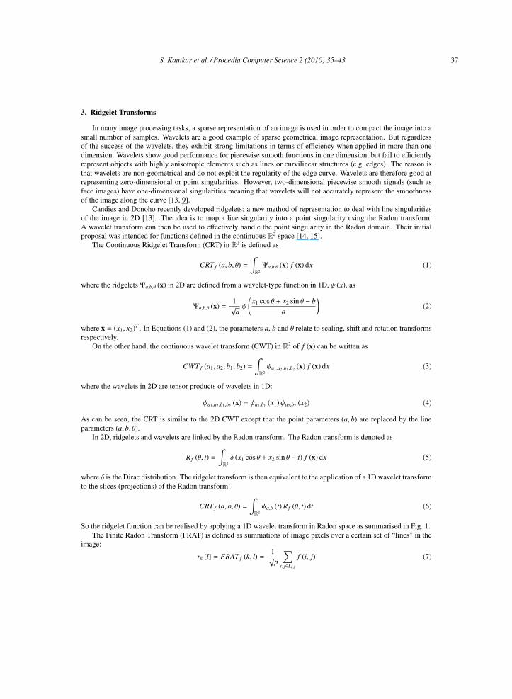
Candies and Donoho recently developed ridgelets: a new method of representation to deal with line singularitiesof the image in 2D [13]. The idea is to map a line singularity into a point singularity using the Radon transform.A wavelet transform can then be used to effectively handle the point singularity in the Radon domain. Their initialproposal was intended for functions defined in the continuous R2 space [14, 15].
The Continuous Ridgelet Transform (CRT) in R2 is defined as
CRT f (a, b, θ) =∫
R2Ψa,b,θ (x) f (x) dx (1)
where the ridgelets Ψa,b,θ (x) in 2D are defined from a wavelet-type function in 1D, ψ (x), as
Ψa,b,θ (x) =1√aψ
(x1 cos θ + x2 sin θ − b
a
)(2)
where x = (x1, x2)T . In Equations (1) and (2), the parameters a, b and θ relate to scaling, shift and rotation transformsrespectively.
On the other hand, the continuous wavelet transform (CWT) in R2 of f (x) can be written as
CWT f (a1, a2, b1, b2) =∫
R2ψa1,a2,b1,b2 (x) f (x) dx (3)
where the wavelets in 2D are tensor products of wavelets in 1D:
ψa1,a2,b1,b2 (x) = ψa1,b1 (x1)ψa2,b2 (x2) (4)
As can be seen, the CRT is similar to the 2D CWT except that the point parameters (a, b) are replaced by the lineparameters (a, b, θ).
In 2D, ridgelets and wavelets are linked by the Radon transform. The Radon transform is denoted as
Rf (θ, t) =∫
R2δ (x1 cos θ + x2 sin θ − t) f (x) dx (5)
where δ is the Dirac distribution. The ridgelet transform is then equivalent to the application of a 1D wavelet transformto the slices (projections) of the Radon transform:
CRT f (a, b, θ) =∫
R2ψa,b (t) Rf (θ, t) dt (6)
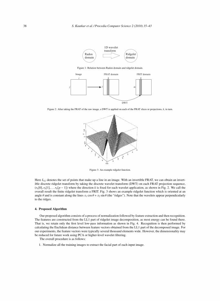
So the ridgelet function can be realised by applying a 1D wavelet transform in Radon space as summarised in Fig. 1.The Finite Radon Transform (FRAT) is defined as summations of image pixels over a certain set of “lines” in the
image:
rk [l] = FRAT f (k, l) =1√p
∑
i, j∈Lk,l
f (i, j) (7)
S. Kautkar et al. / Procedia Computer Science 2 (2010) 35–43 37
S. Kautkar et al. / Procedia Computer Science 00 (2010) 1–9 4
1D wavelettransform
Radondomain
Ridgeletdomain
Figure 1: Relation between Radon domain and ridgelet domain.
Image FRAT domain FRIT domain
i
j l
k
m
k
DWT
Figure 2: After taking the FRAT of the raw image, a DWT is applied on each of the FRAT slices or projections, k, in turn.
Figure 3: An example ridgelet function.
Here Lk,l denotes the set of points that make up a line in an image. With an invertible FRAT, we can obtain an invert-ible discrete ridgelet transform by taking the discrete wavelet transform (DWT) on each FRAT projection sequence,(rk[0], rk[1], . . . rk[p − 1]) where the direction k is fixed for each wavelet application, as shown in Fig. 2. We call theoverall result the finite ridgelet transform a FRIT. Fig. 3 shows an example ridgelet function which is oriented at anangle θ and is constant along the lines x1 cos θ + x2 sin θ (the “ridges”). Note that the wavelets appear perpendicularlyto the ridges.
4. Proposed Algorithm
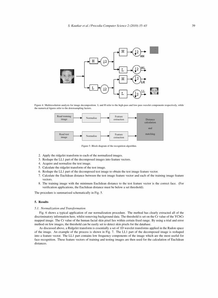
Our proposed algorithm consists of a process of normalization followed by feature extraction and then recognition.The features are constructed from the LL1 part of ridgelet image decomposition, as most energy can be found there.That is, we retain only the first level low-pass information as shown in Fig. 4. Recognition is then performed bycalculating the Euclidean distance between feature vectors obtained from the LL1 part of the decomposed image. Forour experiments, the feature vectors were typically several thousand elements wide. However, the dimensionality maybe reduced for future work using PCA or higher-level wavelet filtering.
The overall procedure is as follows:
1. Normalize all the training images to extract the facial part of each input image.
38 S. Kautkar et al. / Procedia Computer Science 2 (2010) 35–43
S. Kautkar et al. / Procedia Computer Science 00 (2010) 1–9 5
Figure 4: Multiresolution analysis for image decomposition. L and H refer to the high-pass and low-pass wavelet components respectively, whilethe numerical figures refer to the downsampling factors.
Read testimage
Read trainingimage Normalise
Normalise
Featureextraction
Featureextraction
Distancecalculation
and
matching
Figure 5: Block diagram of the recognition algorithm.
2. Apply the ridgelet transform to each of the normalized images.3. Reshape the LL1 part of the decomposed images into feature vectors.4. Acquire and normalize the test image.5. Calculate the ridgelet transform of the test image.6. Reshape the LL1 part of the decomposed test image to obtain the test image feature vector.7. Calculate the Euclidean distance between the test image feature vector and each of the training image feature
vectors.8. The training image with the minimum Euclidean distance to the test feature vector is the correct face. (For
verification applications, the Euclidean distance must be below a set threshold).
The procedure is summarised schematically in Fig. 5.
5. Results
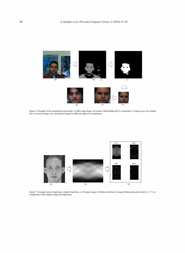
5.1. Normalization and TransformationFig. 6 shows a typical application of our normalization procedure. The method has clearly extracted all of the
discriminatory information here, whilst removing background data. The threshold is set on the Cr value of the YCbCrmapped image. The Cr value of the human facial skin pixel lies within certain fixed range. By using a trial and errormethod on few images, the threshold can be easily set to detect skin pixels for the database.
As discussed above, a Ridgelet transform is essentially a set of 1D wavelet transforms applied in the Radon spaceof the image. An example of the process is shown in Fig. 7. The LL1 part of the decomposed image is reshapedinto a feature vector. The LL1 part contains low frequency components of the image which are the most useful forface recognition. These feature vectors of training and testing images are then used for the calculation of Euclideandistances.
S. Kautkar et al. / Procedia Computer Science 2 (2010) 35–43 39
S. Kautkar et al. / Procedia Computer Science 00 (2010) 1–9 6
Figure 6: Example of the normalization procedure. (a) Raw input image; (b) result of thresholding the Cr component; (c) largest area; (d) croppedface; (e) resized image; (g) a normalized image for different subject for comparison.
Figure 7: Example result of applying a ridgelet transform. (a) Original image; (b) Radon transform of image (Radon projections interval = 3◦); (c)components of the ridgelet image decomposition.
40 S. Kautkar et al. / Procedia Computer Science 2 (2010) 35–43
S. Kautkar et al. / Procedia Computer Science 00 (2010) 1–9 7
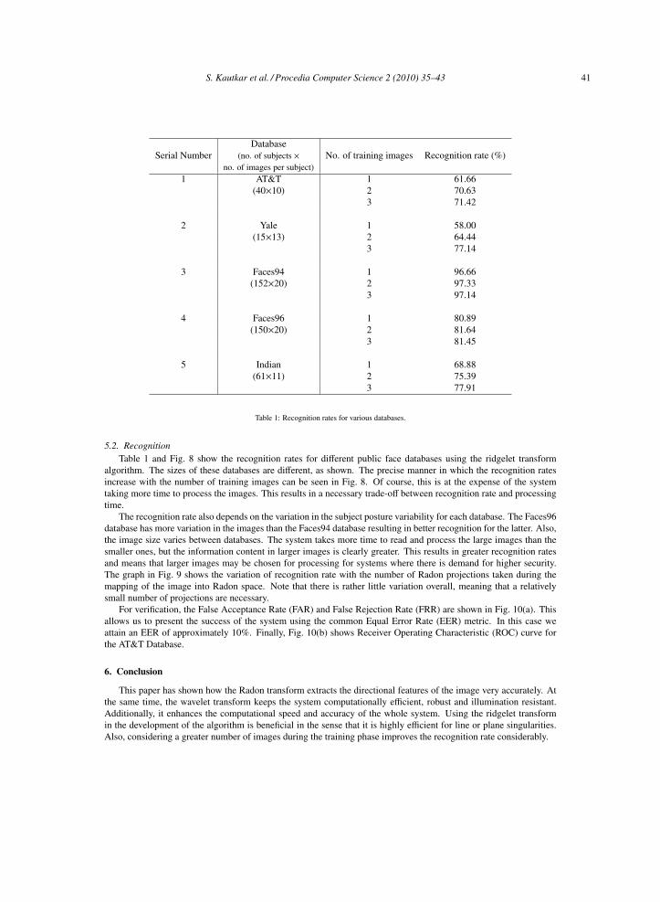
DatabaseSerial Number (no. of subjects × No. of training images Recognition rate (%)
no. of images per subject)1 AT&T 1 61.66
(40×10) 2 70.633 71.42
2 Yale 1 58.00(15×13) 2 64.44
3 77.14
3 Faces94 1 96.66(152×20) 2 97.33
3 97.14
4 Faces96 1 80.89(150×20) 2 81.64
3 81.45
5 Indian 1 68.88(61×11) 2 75.39
3 77.91
Table 1: Recognition rates for various databases.
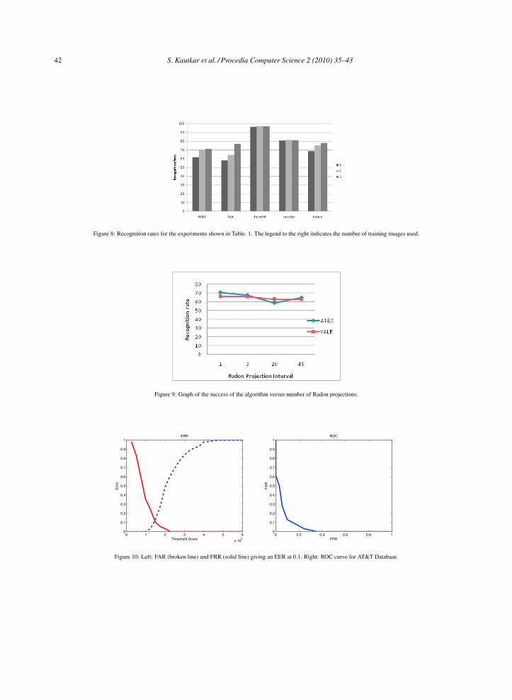
5.2. RecognitionTable 1 and Fig. 8 show the recognition rates for different public face databases using the ridgelet transform
algorithm. The sizes of these databases are different, as shown. The precise manner in which the recognition ratesincrease with the number of training images can be seen in Fig. 8. Of course, this is at the expense of the systemtaking more time to process the images. This results in a necessary trade-off between recognition rate and processingtime.
The recognition rate also depends on the variation in the subject posture variability for each database. The Faces96database has more variation in the images than the Faces94 database resulting in better recognition for the latter. Also,the image size varies between databases. The system takes more time to read and process the large images than thesmaller ones, but the information content in larger images is clearly greater. This results in greater recognition ratesand means that larger images may be chosen for processing for systems where there is demand for higher security.The graph in Fig. 9 shows the variation of recognition rate with the number of Radon projections taken during themapping of the image into Radon space. Note that there is rather little variation overall, meaning that a relativelysmall number of projections are necessary.
For verification, the False Acceptance Rate (FAR) and False Rejection Rate (FRR) are shown in Fig. 10(a). Thisallows us to present the success of the system using the common Equal Error Rate (EER) metric. In this case weattain an EER of approximately 10%. Finally, Fig. 10(b) shows Receiver Operating Characteristic (ROC) curve forthe AT&T Database.
6. Conclusion
This paper has shown how the Radon transform extracts the directional features of the image very accurately. Atthe same time, the wavelet transform keeps the system computationally efficient, robust and illumination resistant.Additionally, it enhances the computational speed and accuracy of the whole system. Using the ridgelet transformin the development of the algorithm is beneficial in the sense that it is highly efficient for line or plane singularities.Also, considering a greater number of images during the training phase improves the recognition rate considerably.
S. Kautkar et al. / Procedia Computer Science 2 (2010) 35–43 41
S. Kautkar et al. / Procedia Computer Science 00 (2010) 1–9 8
Figure 8: Recognition rates for the experiments shown in Table. 1. The legend to the right indicates the number of training images used.
Figure 9: Graph of the success of the algorithm versus number of Radon projections.
0 1 2 3 4 5 6
x 105
0
0.1
0.2
0.3
0.4
0.5
0.6
0.7
0.8
0.9
1
Threshold Score
Err
or
ERR
0 0.2 0.4 0.6 0.8 10
0.1
0.2
0.3
0.4
0.5
0.6
0.7
0.8
0.9
1
FRR
FA
R
ROC
Figure 10: Left: FAR (broken line) and FRR (solid line) giving an EER at 0.1. Right: ROC curve for AT&T Database.
42 S. Kautkar et al. / Procedia Computer Science 2 (2010) 35–43

S. Kautkar et al. / Procedia Computer Science 00 (2010) 1–9 9
7. References
[1] W. Zhao, R. Chellappa (eds), Face Processing: Advanced Modeling and Methods, Elsevier, 2006.[2] W. W. Bledsoe, Man-machine facial recognition: Report on a large-scale experiment, technical report PRI 22, Panoramic Research, Inc., Palo
Alto, California. 1966.[3] M. Kirby, L. Sirovich, Application of Karhunen-Loeve procedure for the characterization of human faces, IEEE Trans. Patt. Anal. Mach.
Intell. 12 (1990) 103–108.[4] W. S. Yambor, Analysis of PCA based and Fisher discriminant based image recognition algorithms, Computer Science Dept, Colorado State
University, Technical Report CS-00-103.[5] A. M. Martı́nez, A. C. Kak, PCA versus LDA, IEEE Trans. Patt. Anal. Mach. Intell. 23 (2001) 228–233.[6] M. Sharkas, M. A. Elenien, Eigenfaces vs. Fisherfaces vs. ICA for face recognition: A comparative study, in: Proc. Signal Proc., 2008, pp.
914–919.[7] C. Liu, Gabor-based kernel PCA with fractional power polynomial models for face recognition, IEEE Trans. Patt. Anal. Mach. Intell. 26
(2004) 572–581.[8] D. V. Jadhav, R. S. Holambe, Feature extraction using radon and wavelet transforms with application to face recognition, Neurocomputing
72 (2008) 1951–1959.[9] M. N. Do, M. Vetterli, The finite ridgelet transform for image representation, IEEE Trans. Im. Proc. 12 (2003) 16–28.
[10] X. J. Jun, N. Lin, Y. Miao, A new digital implementation of ridgelet transform for images of dyadic length, in: Proc. ICITA, 2005, pp. 613 –616.
[11] P. Carri, D. Helhert, E. Andres, 3D fast ridgelet transform, IEEE Trans. Im. Proc. 15 (2006) 3701 – 3714.[12] G. Y. Chen, T. D. Bui, A. Krzyzak, Invariant ridgelet-Fourier descriptor for pattern recognition, in: Proc. ICPR, Vol. 12, 2006, pp. 768 – 771.[13] E. J. Candies, Ridgelets: Theory and applications, Ph.D. thesis, Department of Statistics, Stanford University (1998).[14] S. R. Deans, The Radon Transform and Some of Its Applications, John Wiley and Sons, 1983.[15] J. L. Starck, E. J. Candies, D. Donoho, The curvelet transform for image denoising, IEEE Trans. Im. Proc. 11 (2002) 670–684.
S. Kautkar et al. / Procedia Computer Science 2 (2010) 35–43 43
Related Documents