www.inl.gov Fabrication Process Selection through the Miniplate-1 (MP-1) Experiment I. Glagolenko, N. Woolstenhulme, B. Rabin, D. Keiser, M. Meyer, B. Nielson, J. Parry, M. Lillo, G. Roth, W. Jones, J. Wiest, and S. Snow, INL G. Hofman and E. Wilson, ANL D. Senor, PNNL C. Richardson, B&W 02/26/15

Welcome message from author
This document is posted to help you gain knowledge. Please leave a comment to let me know what you think about it! Share it to your friends and learn new things together.
Transcript

ww
w.in
l.gov
Fabrication Process Selection through the Miniplate-1 (MP-1) Experiment I. Glagolenko, N. Woolstenhulme, B. Rabin, D. Keiser, M. Meyer, B. Nielson, J. Parry, M. Lillo, G. Roth, W. Jones, J. Wiest, and S. Snow, INL G. Hofman and E. Wilson, ANL D. Senor, PNNL C. Richardson, B&W 02/26/15

Needed LEU fuel for conversion of five US High Power Research Reactors (US HPRR)
US High Performance Research Reactor (US HPRR)
Regulatory Agency
1 Massachusetts Institute of Technology Reactor (MITR) Nuclear Regulatory
Commission (NRC)
2 Missouri University Research Reactor (MURR) 3 National Bureau of Standards Reactor (NBSR) 4 High Flux Isotope Reactor (HFIR) Department of
Energy (DOE) 5 Advanced Test Reactor (ATR)
Challenge: one type of fuel for different end-use applications
2

Selected Design Monolithic LEU U-10Mo fuel with Zr diffusion barrier
August 2009: Favorable performance in the limited number of irradiation tests:
9 miniplates (RERTR-9,-10) 2 large size plates (AFIP-2 and AFIP-3)
Additional data became available for this fuel design later: 56 miniplates (RERTR-12), 11 larger size plates (AFIP-4, AFIP-6, AFIP-6-MKII, AFIP-7)
3
Al-6061 cladding U-Mo monolithic foil
(0.2 – 0.635 mm thick)
Co-rolled Zr barrier (0.0254 mm thick)
Plate (1.1 mm – 2.54 mm thick)

Reference Fuel fabrication process Bench scale reference process developed at INL • Down-blending and alloying • U-Mo casting and coupon preparation • Hot rolling of U-Mo with Zr barrier in a welded can assembly • De-canning of the U-Mo/Zr foil • Annealing of the foil, if desired • Cold rolling of the foil to final thickness • Foil shearing • Foil cleaning • Bonding of the foil and cladding at 560 °C using Hot Isostatic Press (HIP)
4

Challenges Scaling of the fabrication process
5
Not commercially viable: low yield inefficient poor uranium
resource utilization high cost of waste
reprocessing
INL bench-scale reference fabrication
process
Large scale reference fabrication
process Scale-up
2.54 cm × 10.16 cm 10.06 cm× 125.73 cm

Key to Success
6
Successful Fuel Product
Efficient and Economical Fabrication
Process
Acceptable Irradiation
Performance

New Focus Develop commercially viable fabrication process
7
Fuel Fabrication Capability (FFC) is in charge
Stage Gate Approach in Fabrication Process Selection Improve yield
Minimize waste Reduce cost
Optimize existing (baseline) fabrication process
Develop/implement alternative fabrication methods
Detailed information about FFC activities is in Doug Burkes’s
presentation on Friday
Examples of Fabrication method Improvements
8
• Reduction of U-waste by changing Zr barrier application method
• Reduction of cost by switching to can-less HIP
Key: new fabrication technologies have to be demonstrated at large scale
No barrier
Zr barrier application
Co-rolling
Plasma spray
Electro-plating
Cladding bonding
Hot Isostatic Press (HIP)
Can-less HIP

New Focus
9
MP-1 test is a platform for achieving this mission
Base Fuel Designs
• no fuel grading
• no poisons
Reactors MURR, MIT,
NBSR
Single Fab. Process
Compatible with ATR/HFIR
Commercial Viability Deploy and demonstrate
commercially viable fabrication methods at large
scale far in advance of irradiation tests
Adequate Irradiation Performance
Demonstrate irradiation performance as a function
of fabrication process
Downselect Select fabrication process
suitable to be qualified for LEU conversion

Evaluation of Fuel Performance: Miniplate-1 (MP-1) irradiation test
• Fabrication process downselect test • All test specimens manufactured using fabrication processes that meet
“commercial viability” requirements • Miniplate scale • Base fuel designs • Prototypic irradiation conditions/plate geometries • Focus on evaluation of irradiation performance against a set of
established criteria • Development of key relationships:
10
Fabrication process
Microstructure/ properties
Irradiation performance

Role of MP-1 in US HPRR Fuel Development Program
11
Base Fuel Qualification
Report submitted to NRC
MP-1 Screening/downselect test, miniplate scale
MP-2 Fuel qualification test
miniplate scale
FSP-1 Fuel qualification test full-size plate scale
ET-1 Fuel qualification test
fuel element scale
Base fuel fabrication process selected for qualification Fuel specification defined
Detailed information about base fuel qualification is in
Nic Woolstenhulme’s presentation on
Friday

MP-1 Designing by the Rules • Design to meet safety and program requirements • Be prototypic as much as feasible:
– use LEU instead of HEU – prototypic geometries (fuel meat/cladding thickness) – commercial fab processes – prototypic irradiation conditions
• Obtain statistical confidence to enable good downselect decision • Reduce the risk of in-reactor failure as much as possible
12

MP-1 Fabrication Requirements • Miniplates are manufactured by commercial supplier (B&W) using
commercially viable processes: – optimized baseline – alternative
• MP-1 fuel specification requires demonstration of selected fabrication processes at full scale
• Miniplates are representative of the full scale products and meet established fuel specification
• Entry requirement for MP-1 test – Fabrication processes meet Technology Readiness Level 4 (TRL- 4)
• economics (capital and life cycle cost) • technical maturity • suitability for implementation • lead time for deployment
13

MP-1 Matrix (Evolving)
14
Fabrication Process Variables
Fuel
Specimens
Coupon fabrication
Zr barrier application
Fuel foil edge conditions
Cladding bonding
Optimized FY16 baseline
Billet casting and bare rolling
No barrier
Co-rolling
Plasma spray
Electro-plating
Not-covered (co-roll, plasma-spray)
Hot Isostatic Press (HIP)
Can-less HIP
Covered (electroplating)
Reference Fuel
Specimens

MP-1 Selecting plate geometries and irradiation conditions for testing
Five Reactors: • Variety of plate designs (fuel meat/cladding thicknesses) coupled with
unique operating conditions • Striving to be prototypic
15
Plate 19
Plate 15
Plate 19
Plate 15
Dispersion • The same fuel meat thickness • Plate with the highest power density
is the plate with the highest heat flux
Monolithic • Multiple fuel foil thicknesses • Plate 19 – highest power density • Plate 15 – highest heat flux

Reactor plates limiting operating conditions vs. MP-1 targets
16
MP-1 high power target: 0.0085”, 0.05”
MP-1 medium power target: 0.0085”, 0.05” MP-1 low
power target: 0.025”, 0.05”
ATR- thick foil: 0.016”, 0.05”
ATR-thin foil: 0.008”, 0.05”
MURR-thin foil: 0.009”, 0.044”
MURR-thick foil:
0.020”, 0.044”
NBSR: 0.0085”, 0.05”
MITR-thin foil: 0.013”, 0.049” MITR-thick foil:
0.025”, 0.049” 0
10
20
30
40
50
0 1 2 3 4 5 6 7 8
Plat
e pe
ak p
ower
(r
eact
or s
peci
fic n
ode)
, kW
/cc
Plate peak burnup (reactor specific node), × E21 fiss/cc

Selection of plate geometries / irradiation conditions for MP-1
17
ATR, (HFIR)
thickest meat low power,
med-burnup
thin meat med power,
highest burnup
thin meat highest power,
low-to-med burnup
NBSR, MURR-1 MURR-22, MITR

Fab Process #1
Fab Process #2
Fab Process #3 Test Condition #1
low power, med-burnup
Test Condition #2 medium power,
high burnup
Test Condition #3
high power, low-to-med burnup
And the Winner is … Fab Process X !!! EXPERT JURY
Geometry #1 thick meat
Geometry #2 thin meat
Geometry #2 thin meat
. . .
Essence of MP-1
18
Fabrication + Performance Requirements

MP-1 Matrix Specimen Category
Coupon Fab Method
Foil Trimming
Clad Bonding
Fuel Meat, Plate
thickness (inches)
Power, Burnup
Zirconium Application and Edge Condition
Co-roll Plasma Spray Electroplating No Zirconium (Uncovered) (Uncovered) (Covered)
Fabrication Process Variables
FY16 Optimized Baseline
(Billet Cast and Bare
Roll)
Slitting
HIP
0.0085, 0.049 52.5, 5.5 FFC-1-1 FFC-5-1 FFC-6-1
0.0085, 0.049 17.6, 7.6 FFC-1-2 FFC-5-2 FFC-6-2 FFC-4-2
0.025, 0.049 7.7, 4.0 FFC-1-3 FFC-5-3 FFC-6-3 FFC-4-3
Alternate (Canless
HIP)
0.0085, 0.049 52.5, 5.5 FFC-8-1 FFC-7-1 FFC-9-1
0.0085, 0.049 17.6, 7.6 FFC-8-2 FFC-7-2 FFC-9-2 FFC-12-2
0.025, 0.049 7.7, 4.0 FFC-8-3 FFC-7-3 FFC-9-3 FFC-12-3
Reference Process (modified geometry)
Old Reference Shear HIP
0.0085, 0.049 52.5, 5.5 FD-11-1
0.0085, 0.049 17.6, 7.6 FD-11-2
0.025, 0.049 7.7, 4.0 FD-11-3
19
• 4 replicates for each specimen type • 28 specimens in high power conditions • 36 specimens in medium power conditions • 36 specimens in low power conditions • Additional archives and substitutes
100 specimens total to be irradiated: 72 LEU + 28 HEU

LEU Advantages
• Prototypic enrichment • Prototypic fabrication line • Representative power
history • Less spread in power
among specimens in the flux trap
• Less spread in burnup
Consequences
• Longer irradiation time • Need for higher flux flux
trap (NBSR case) • Harder to match target
power = can’t use enrichment to adjust power
• Limited number of suitable test positions within one test train
20
ATR- and HFIR-like conditions still require HEU!

MP-1 Test Capsule Hf suppressors to reduce power peaking
Benefits Reduces power
peaking to allow thermal safety requirements for experiment insertion to be met
Helps to avoid failures at non-prototypic conditions
21
Courtesy of Jim Wiest

Courtesy of Nic Woolstenhulme
MP-1 Hardware Design Large-B Position
Irradiation Vehicle
South Flux Trap Irradiation Vehicle
• Two side-by-side channels, a.k.a ‘double barrel design’
• Fits more specimens at the same axial flux level → with the same power
• Provides more efficient cooling configuration for high power specimens
22

B-12 B-10
B-11 South Flux Trap (SFT)
MP-1 Test Positions in ATR
23

Low Power Test in Large B Test Position
24
• MITR – MURR-22 condition • All plates are LEU • With Hf suppressors • Up to 26% higher than bounding
conversion element power • Number of useful positions (in red)
per one large B test train = 14 • Need to fit 36 specimens 3 large
B test trains • Each specimen type is isolated in
individual capsule • 5-6 cycles to reach target burnup
Courtesy of Nic Woolstenhulme

Medium Power Test in South Flux Trap
25
• NBSR – MURR-1 condition • All plates are LEU • Without Hf suppressors • Up to 58% higher than conversion
element bounding power • Number of useful positions (in red) = 32 • Need to fit 36 specimens 4 mini-
plates short • Specimens without Zr barrier are
isolated in individual capsule • Two specimen types are in one capsule • 6-7 cycles to reach target burnup
Courtesy of Nic Woolstenhulme
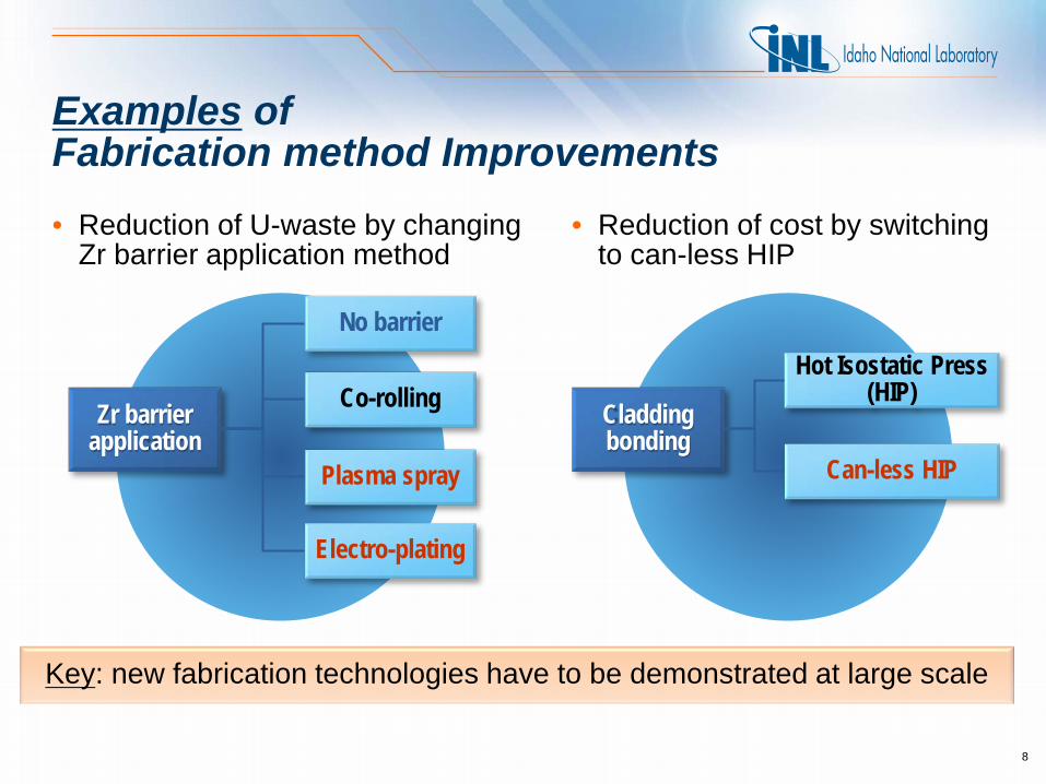
High Power Test in South Flux Trap
26
• ATR condition • All plates are HEU (A% and B%) • With Hf suppressors • Number of useful positions (in red) = 32 • Need to fit 28 specimens • No specimens without Zr barrier • ~ 1 cycle to reach target burnup
Courtesy of Nic Woolstenhulme

Irradiation Schedule
27
Test Test Position ATR Cycles 1 2 3 4 5 6 7 8
CIC
Low Power Three large B’s X X X X X X
Medium Power South Flux Trap X X X X X X X High Power South Flux Trap X
Channel gap probe measurements and data
interpretation
As-run analysis for the previous cycle and
projections for the next cycle
Risk assessment against ‘requirements based exit criteria’
‘Go/no go’decision per capsule basis
In-between cycles

Irradiation Performance
28
Mechanical Integrity • no in-core blistering • blister threshold temperature is
known acceptable • no excessive swelling • no plate deformation or movement • thermo-physical properties affecting
geometric stability are known
Stable and Predictable Behavior
• no fission product release • no delamination (bond integrity) • no in-core blistering • blister threshold temperature is known
and acceptable • no warping or buckling • fuel microstructure is stable • mechanical properties are known and
acceptable • mechanical stresses are known • thermo-physical properties affecting
mechanical integrity are known • no excessive cladding corrosion • limits for fabrication defects are
established
• swelling is known and acceptable
• fuel microstructure is stable, no obvious precursors to failure
– large gas bubbles
– interconnected porosity
• thermo-physical properties affecting fuel stability are known
• blister threshold temperature is known and acceptable
Geometric Stability
Acceptable Irradiation
Performance Geometric Stability
Mechanical Integrity
Stable and Predictable Behavior
Detailed information about PIE activities is in Adam Robinson’s
presentation on Friday

MP-1 Benefit to the Program • MP-1 will provide irradiation performance data for the fabrication
processes: – that have lower cost, produce less waste and are more efficient – that have been demonstrated to be scalable and commercially
viable – with good statistical confidence to enable solid fabrication process
down-select decision • MP-1 will deliver fuel/fabrication process for future fuel qualification and
ultimate reactor conversion
29
Related Documents