Surfaces, Interfaces and Coatings Technology 1 www.videleaf.com Book Chapter Fabrication of Co-Ni based Superhydrophobic Coating and its Wear Resistance, Durability and Corrosion Resistance Yanpeng Xue* and Shuqiang Wang National Center for Materials Service Safety, University of Science and Technology Beijing, China *Corresponding Author: Yanpeng Xue, National Center for Materials Service Safety, University of Science and Technology Beijing, Xueyuan Road 30, 100083 Beijing, China Published June 16, 2021 How to cite this book chapter: Yanpeng Xue, Shuqiang Wang. Fabrication of Co-Ni based Superhydrophobic Coating and its Wear Resistance, Durability and Corrosion Resistance. In: Alessio Bosio, editor. Surfaces, Interfaces and Coatings Technology. Hyderabad, India: Vide Leaf. 2021. © The Author(s) 2021. This article is distributed under the terms of the Creative Commons Attribution 4.0 International License(http://creativecommons.org/licenses/by/4.0/), which permits unrestricted use, distribution, and reproduction in any medium, provided the original work is properly cited. Acknowledgement: The authors thank the support from Fundamental Research Funds for the Central Universities China (Project ID: FRF-TP-20-049A2). And the project was also supported by the Tribology Science Fund of State Key Laboratory of Tribology.

Welcome message from author
This document is posted to help you gain knowledge. Please leave a comment to let me know what you think about it! Share it to your friends and learn new things together.
Transcript
Surfaces, Interfaces and Coatings Technology
1 www.videleaf.com
Book Chapter
Fabrication of Co-Ni based
Superhydrophobic Coating and its Wear
Resistance, Durability and Corrosion
Resistance
Yanpeng Xue* and Shuqiang Wang
National Center for Materials Service Safety, University of
Science and Technology Beijing, China
*Corresponding Author: Yanpeng Xue, National Center for Materials Service Safety, University of Science and Technology
Beijing, Xueyuan Road 30, 100083 Beijing, China
Published June 16, 2021
How to cite this book chapter: Yanpeng Xue, Shuqiang Wang.
Fabrication of Co-Ni based Superhydrophobic Coating and its Wear Resistance, Durability and Corrosion Resistance. In:
Alessio Bosio, editor. Surfaces, Interfaces and Coatings
Technology. Hyderabad, India: Vide Leaf. 2021.
© The Author(s) 2021. This article is distributed under the terms
of the Creative Commons Attribution 4.0 International License(http://creativecommons.org/licenses/by/4.0/), which
permits unrestricted use, distribution, and reproduction in any
medium, provided the original work is properly cited.
Acknowledgement: The authors thank the support from
Fundamental Research Funds for the Central Universities China
(Project ID: FRF-TP-20-049A2). And the project was also supported by the Tribology Science Fund of State Key
Laboratory of Tribology.
Surfaces, Interfaces and Coatings Technology
2 www.videleaf.com
Introduction
Super-hydrophobic surfaces inspired by biological species have been extensively concerned due to their potential applications in
corrosion protection [1,2], anti-icing [3,4], water/oil separation
[5] and drag reduction [6]. Techniques to make
superhydrophobic surfaces can be simply divided into two categories: making a rough surface from a low surface energy
material or modifying a rough surface with a material of low
surface energy [7,8]. Many methods have been developed to produce rough surfaces, including plasma etching [9], chemical
vapor deposition [10], solgel method [11], and electrodeposition
[12]. Most of these methods involved multi-step procedures and
harsh conditions, or require specialized reagents and equipment. In contrast, electrodeposition has been used as a one step, simple
and economic method to fabricate superhydrophobic surface on
different substrates. Up to now, a few papers have been published on superhydrophobic nickel films produced by
electrodeposition without applying low surface energy materials
[13,14]. These researches have usually studied the morphology and wetting behavior of the coatings. Ni coatings prepared by
electrochemical deposition have been studied extensively, which
exhibit excellent corrosion protection [15].
S. Esmailzadeh et al. [1] fabricated hierarchical nickel films on
copper substrate by two-step electrodeposition process. In this
work, the corrosion resistant and superhydrophobic nickel films with a hierarchical structure were synthesized by directional
electrodeposition process. The relationship between the
wettability and surface morphology was studied under different deposition current densities.
However, only limited studies were concerned about the Ni-Co
alloy coatings with micro-nanostructures. Silva et al. [16] deposited Ni-Co surfaces with a 3D hierarchical open porous
structure by applying a square current wave form on austenitic
stainless steel substrates. Xue et al. [17] prepared bimetallic Ni-Co coating with novel hierarchical micro-spherical structures on
carbon steel substrate. The properties including surface
morphologies, structures, chemical compositions, wetting
Surfaces, Interfaces and Coatings Technology
3 www.videleaf.com
properties, as well as the growth mechanism of the
electrodeposited hierarchical structure were observed. However, one of the major drawbacks to overcome for practical
applications of super-hydrophobic coating, is its mechanical
durability due to its fragile micro-nano structures, which is
behind the surface super-hydrophobic property [18,19].
In our works, to improve the mechanical durability of the Ni-Co
superhydrophobic coating, many attempts have been made such as increasing the cobalt content and adding the second particle
WC and CeO2 on the electrolyte solutions.
Preparation of Co-Ni based Superhydrophobic
Coating Co-Ni Superhydrophobic Coating
A new low-cost process preparation for super-hydrophobic Co-
Ni coating was prepared on carbon steel substrate via an electrodeposition route [20]. The Co-Ni coatings were deposited
at a constant potential of −1.0, −1.4 and −1.7 V for 3000 s at
room temperature in mixed solution CoCl2 0.1 mol/L + NiCl2 0.03 mol/L + H3BO3 0.1 mol/L. For the bare carbon steel, the
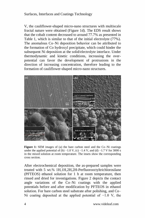
polished surface displayed lots of scratches (Figure 1a). After
electrochemical deposition under the applied potential at −1.0 V for 3000 s in the above-mentioned solution, the carbon steel
surface was covered by uniform granular structures containing
average size of sub-micrometer in diameter and the as-polished
scratches were covered completely (Figure 1b). As shown in the cross-section view, the thickness of the coating is around 26 μm
for the deposition time of 3000 s, and the EDS result showed that
the cobalt content is around 93.8%, which is higher than that of the initial electrolyte (77%, CoCl2 0.1 mol/L NiCl2 0.03 mol/L).
After the deposition at −1.4 V for 3000 s, the coating surface
evidenced lots of spherical humps with an average size of 33 μm and a large number of cracks (Figure 1c), which may be
attributed to the internal stress generated during the
electrochemical deposition process. The cross-section image
revealed that the thickness of the coating was around 40 μm and the large spherical humps grew from the thin layer composed of
small irregular crystals. Increasing the applied potential to −1.7
Surfaces, Interfaces and Coatings Technology
4 www.videleaf.com
V, the cauliflower-shaped micro-nano structures with multiscale
fractal nature were obtained (Figure 1d). The EDS result shows that the cobalt content decreased to around 77.7% as presented in
Table 1, which is similar to that of the initial electrolyte (77%).
The anomalous Co–Ni deposition behavior can be attributed to
the formation of Co hydroxyl precipitate, which could hinder the subsequent Ni deposition at the solid/electrolyte interface. Under
thermodynamic and kinetic conditions, increasing the over-
potential can favor the development of protrusions in the direction of increasing concentration, therefore leading to the
formation of cauliflower-shaped micro-nano structures.
Figure 1: SEM images of (a) the bare carbon steel and the Co–Ni coatings under the applied potential of (b) −1.0 V, (c) −1.4 V, and (d) −1.7 V for 3000 s in the mixed solution at room temperature. The insets show the corresponding cross section.
After electrochemical deposition, the as-prepared samples were
treated with 5 wt.% 1H,1H,2H,2H-Perfluorooctyltrichlorosilane (PFTEOS) ethanol solution for 1 h at room temperature, then
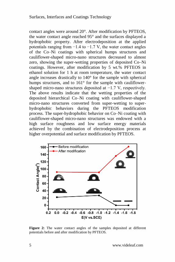
rinsed and dried for investigations. Figure 2 depicts the contact
angle variations of the Co–Ni coatings with the applied potentials before and after modification by PFTEOS in ethanol
solution. For bare carbon steel substrate after polishing, and Co–
Ni coating deposited at the applied potential of −1.0 V, the
Surfaces, Interfaces and Coatings Technology
5 www.videleaf.com
contact angles were around 20°. After modification by PFTEOS,
the water contact angle reached 95° and the surfaces displayed a hydrophobic property. After electrodeposition at the applied
potentials ranging from −1.4 to −1.7 V, the water contact angles
of the Co–Ni coatings with spherical humps structures and
cauliflower-shaped micro-nano structures decreased to almost zero, showing the super-wetting properties of deposited Co–Ni
coatings. However, after modification by 5 wt.% PFTEOS in
ethanol solution for 1 h at room temperature, the water contact angle increases drastically to 140° for the sample with spherical
humps structures, and to 161° for the sample with cauliflower-
shaped micro-nano structures deposited at −1.7 V, respectively. The above results indicate that the wetting properties of the
deposited hierarchical Co–Ni coating with cauliflower-shaped
micro-nano structures converted from super-wetting to super-
hydrophobic behaviors during the PFTEOS modification process. The super-hydrophobic behavior on Co–Ni coating with
cauliflower-shaped micro-nano structures was endowed with a
high surface roughness and low surface energy materials achieved by the combination of electrodeposition process at
higher overpotential and surface modification by PFTEOS.
Figure 2: The water contact angles of the samples deposited at different potentials before and after modification by PFTEOS.
Surfaces, Interfaces and Coatings Technology
6 www.videleaf.com
Co-Ni/WC Superhydrophobic Coating
In order to further improve the mechanical durability of the Co-
Ni coating, robust super-hydrophobic cobalt-nickel coatings
reinforced by micro-nano tungsten carbide (WC) particles were achieved on carbon steel substrate by electrochemical deposition
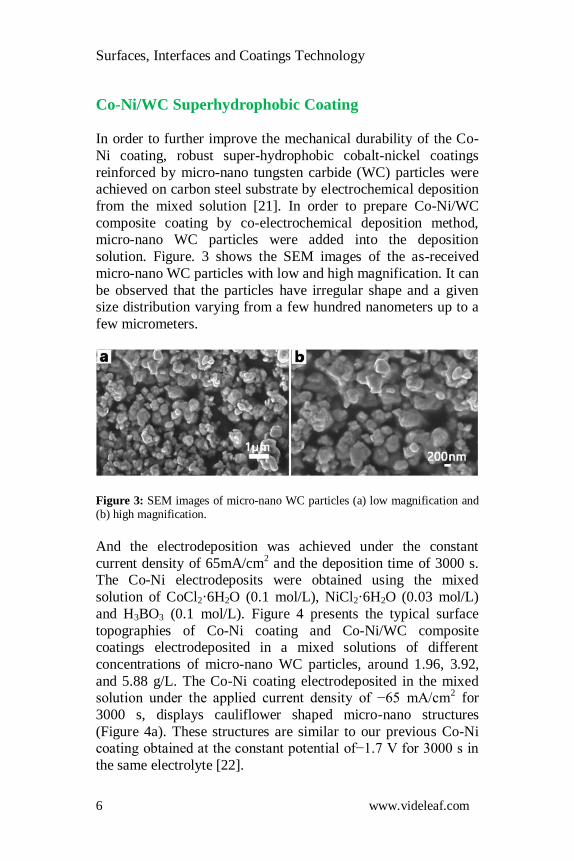
from the mixed solution [21]. In order to prepare Co-Ni/WC
composite coating by co-electrochemical deposition method, micro-nano WC particles were added into the deposition
solution. Figure. 3 shows the SEM images of the as-received
micro-nano WC particles with low and high magnification. It can
be observed that the particles have irregular shape and a given size distribution varying from a few hundred nanometers up to a
few micrometers.
Figure 3: SEM images of micro-nano WC particles (a) low magnification and (b) high magnification.
And the electrodeposition was achieved under the constant
current density of 65mA/cm2 and the deposition time of 3000 s.
The Co-Ni electrodeposits were obtained using the mixed
solution of CoCl2·6H2O (0.1 mol/L), NiCl2·6H2O (0.03 mol/L)
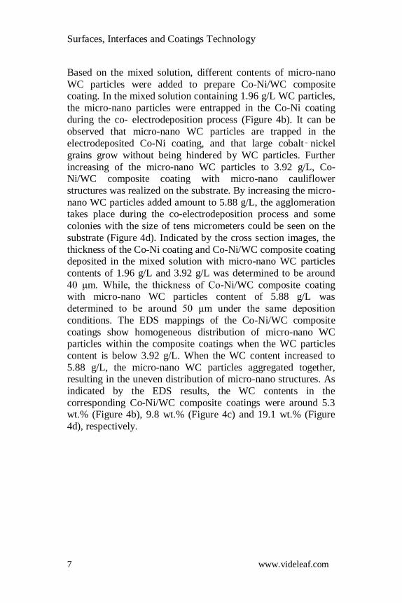
and H3BO3 (0.1 mol/L). Figure 4 presents the typical surface
topographies of Co-Ni coating and Co-Ni/WC composite coatings electrodeposited in a mixed solutions of different
concentrations of micro-nano WC particles, around 1.96, 3.92,
and 5.88 g/L. The Co-Ni coating electrodeposited in the mixed solution under the applied current density of −65 mA/cm
2 for
3000 s, displays cauliflower shaped micro-nano structures
(Figure 4a). These structures are similar to our previous Co-Ni coating obtained at the constant potential of−1.7 V for 3000 s in
the same electrolyte [22].
Surfaces, Interfaces and Coatings Technology
7 www.videleaf.com
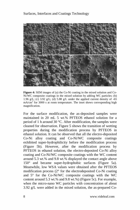
Based on the mixed solution, different contents of micro-nano
WC particles were added to prepare Co-Ni/WC composite coating. In the mixed solution containing 1.96 g/L WC particles,
the micro-nano particles were entrapped in the Co-Ni coating
during the co- electrodeposition process (Figure 4b). It can be
observed that micro-nano WC particles are trapped in the
electrodeposited Co-Ni coating, and that large cobalt‑ nickel
grains grow without being hindered by WC particles. Further
increasing of the micro-nano WC particles to 3.92 g/L, Co-Ni/WC composite coating with micro-nano cauliflower
structures was realized on the substrate. By increasing the micro-
nano WC particles added amount to 5.88 g/L, the agglomeration takes place during the co-electrodeposition process and some
colonies with the size of tens micrometers could be seen on the
substrate (Figure 4d). Indicated by the cross section images, the
thickness of the Co-Ni coating and Co-Ni/WC composite coating deposited in the mixed solution with micro-nano WC particles
contents of 1.96 g/L and 3.92 g/L was determined to be around
40 μm. While, the thickness of Co-Ni/WC composite coating with micro-nano WC particles content of 5.88 g/L was
determined to be around 50 μm under the same deposition
conditions. The EDS mappings of the Co-Ni/WC composite
coatings show homogeneous distribution of micro-nano WC particles within the composite coatings when the WC particles
content is below 3.92 g/L. When the WC content increased to
5.88 g/L, the micro-nano WC particles aggregated together, resulting in the uneven distribution of micro-nano structures. As
indicated by the EDS results, the WC contents in the
corresponding Co-Ni/WC composite coatings were around 5.3 wt.% (Figure 4b), 9.8 wt.% (Figure 4c) and 19.1 wt.% (Figure
4d), respectively.
Surfaces, Interfaces and Coatings Technology
8 www.videleaf.com
Figure 4: SEM images of (a) the Co-Ni coating in the mixed solution and Co-Ni/WC composite coatings in the mixed solution by adding WC particles: (b) 1.96 g/L; (c) 3.92 g/L; (d) 5.88 g/L under the applied current density of -65 mA/cm2 for 3000 s at room temperature. The inset shows corresponding high magnification.
For the surface modification, the as-deposited samples were
maintained in 20 mL 5 wt.% PFTEOS ethanol solution for a period of 1 h around 30 °C. After modification, the samples were
cleaned for observation. Figure 5 shows the transition of wetting
properties during the modification process by PFTEOS in ethanol solution. It can be observed that all the electro-deposited
Co-Ni alloy coating and Co-Ni/WC composite coatings
exhibited super-hydrophilicity before the modification process
(Figure 5b). However, after the modification process by PFTEOS in ethanol solution, the electro-deposited Co-Ni alloy
coating and Co-Ni/WC composite coatings with the WC content
around 5.3 wt.% and 9.8 wt.% displayed the contact angle above 150° and became super-hydrophobic surfaces (Figure 5a).
Meanwhile, low WSA values were obtained after the PFTEOS
modification process (2° for the electrodeposited Co-Ni coating
and 5° for the Co-Ni/WC composite coatings with the WC content around 5.3 wt.% and 9.8 wt.%) (Figure 5c). For example,
when the micro-nano WC particles with concentration of about
3.92 g/L were added in the mixed solution, the as-prepared Co-
Surfaces, Interfaces and Coatings Technology
9 www.videleaf.com
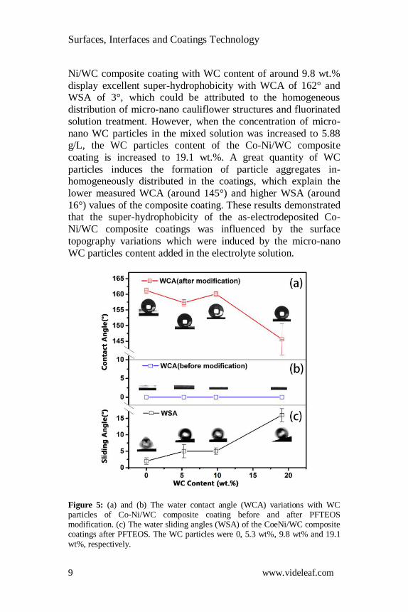
Ni/WC composite coating with WC content of around 9.8 wt.%
display excellent super-hydrophobicity with WCA of 162° and WSA of 3°, which could be attributed to the homogeneous
distribution of micro-nano cauliflower structures and fluorinated
solution treatment. However, when the concentration of micro-
nano WC particles in the mixed solution was increased to 5.88 g/L, the WC particles content of the Co-Ni/WC composite
coating is increased to 19.1 wt.%. A great quantity of WC
particles induces the formation of particle aggregates in-homogeneously distributed in the coatings, which explain the
lower measured WCA (around 145°) and higher WSA (around
16°) values of the composite coating. These results demonstrated that the super-hydrophobicity of the as-electrodeposited Co-
Ni/WC composite coatings was influenced by the surface
topography variations which were induced by the micro-nano
WC particles content added in the electrolyte solution.
Figure 5: (a) and (b) The water contact angle (WCA) variations with WC particles of Co-Ni/WC composite coating before and after PFTEOS modification. (c) The water sliding angles (WSA) of the CoeNi/WC composite coatings after PFTEOS. The WC particles were 0, 5.3 wt%, 9.8 wt% and 19.1
wt%, respectively.
Surfaces, Interfaces and Coatings Technology
10 www.videleaf.com
Co-Ni/CeO2 Superhydrophobic Coating
Up to now, Rare-earth oxides (REOs) as a second phase particles
received less attention on the preparation of super-hydrophobic
coatings. Metal atoms in REOs have a lower tendency to exchange electrons and form a hydrogen bond with interfacial
water molecules, which is an effective way to build super-
hydrophobic surfaces. Because of their unique electronic structure, Rare-earth oxides (REOs) have been proven to be
intrinsically hydrophobic [23]. Herein, cerium oxide particles
(CeO2) are added to the coating by co-electrodeposition. The Co-
Ni/CeO2 composite coatings are obtained in the mixed solution with CoCl2·6H2O (0.1 mol/L), NiCl2·6H2O (0.03 mol/L), H3BO3
(0.1 mol/L) and different amounts of CeO2 particles in the
solution [24]. To ensure uniform distribution of micro-nano CeO2 particles in the coating, the magnetic stirrer (Model SH-2,
Input 220 V 50/60 HZ) is used and adjusted to approximately
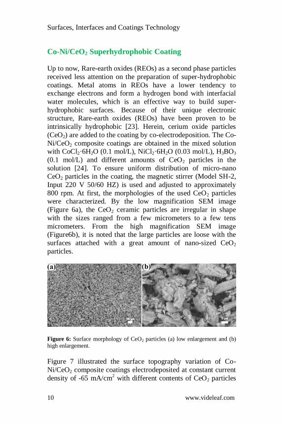
800 rpm. At first, the morphologies of the used CeO2 particles were characterized. By the low magnification SEM image
(Figure 6a), the CeO2 ceramic particles are irregular in shape
with the sizes ranged from a few micrometers to a few tens
micrometers. From the high magnification SEM image (Figure6b), it is noted that the large particles are loose with the
surfaces attached with a great amount of nano-sized CeO2
particles.
Figure 6: Surface morphology of CeO2 particles (a) low enlargement and (b) high enlargement.
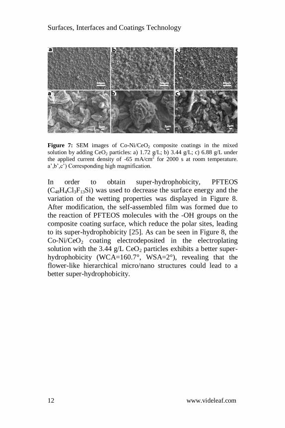
Figure 7 illustrated the surface topography variation of Co-
Ni/CeO2 composite coatings electrodeposited at constant current
density of -65 mA/cm2 with different contents of CeO2 particles
Surfaces, Interfaces and Coatings Technology
11 www.videleaf.com
added in the above-mentioned mixed solution. When the content
of CeO2 particles in the electrolyte solution was 1.72 g/L, irregular diamond-like structures having a diameter of about
several micrometers were aggregated to form a larger-sized
irregular structure, and distributed uniformly over the entire
surface (Figure7a and 7d). After doubling the CeO2 content to 3.44 g/L, parts of the diamond structures were replaced by the
flaky fish scale structures, and further aggregated into the
flower-like micro/nano hierarchical structures (Figure 7b and 7e). With the CeO2 content rose to 6.88 g/L in the mixed
solution, the flower-like micro/nano hierarchical structures were
replaced by locally aggregated CeO2 clusters, which were distributed inhomogeneously on the surface (Figure 7c and 7f).
According to the cross section images, the thickness of the
composite coating electrodeposited in the mixed solution
containing CeO2 particles of 1.72 g/L was around 15 μm after the deposition time of 2000 s. With the increase of the CeO2
particles to 3.44 g/L, the thickness of the electrodeposited
composite coating increased to 20 μm. However, by adding the CeO2 particles to 6.88 g/L, the electrodeposited coating’s
thickness decreased to 16 μm, which could be attributed to the
difficulty of co-electrodeposition due to the large amount of CeO2 particles. According to the EDS analysis, the CeO2
contents were around 12.4 wt.% (Figure7a), 15.6 wt.%
(Figure7b) and 19.1 wt.% (Figure7c) in the corresponding Co-
Ni/CeO2 composite coatings respectively. Under the same deposition conditions, the CeO2 content in the coatings gradually
increased while the nickel in the composite deposits content
decreased.
Surfaces, Interfaces and Coatings Technology
12 www.videleaf.com
Figure 7: SEM images of Co-Ni/CeO2 composite coatings in the mixed
solution by adding CeO2 particles: a) 1.72 g/L; b) 3.44 g/L; c) 6.88 g/L under the applied current density of -65 mA/cm2 for 2000 s at room temperature. a’,b’,c’) Corresponding high magnification.
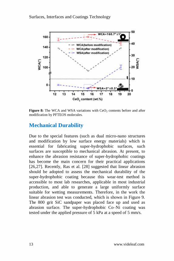
In order to obtain super-hydrophobicity, PFTEOS (C48H4Cl3F13Si) was used to decrease the surface energy and the
variation of the wetting properties was displayed in Figure 8.
After modification, the self-assembled film was formed due to the reaction of PFTEOS molecules with the -OH groups on the
composite coating surface, which reduce the polar sites, leading
to its super-hydrophobicity [25]. As can be seen in Figure 8, the
Co-Ni/CeO2 coating electrodeposited in the electroplating solution with the 3.44 g/L CeO2 particles exhibits a better super-
hydrophobicity (WCA=160.7°, WSA=2°), revealing that the
flower-like hierarchical micro/nano structures could lead to a better super-hydrophobicity.
Surfaces, Interfaces and Coatings Technology
13 www.videleaf.com
Figure 8: The WCA and WSA variations with CeO2 contents before and after
modification by PFTEOS molecules.
Mechanical Durability Due to the special features (such as dual micro-nano structures
and modification by low surface energy materials) which is
essential for fabricating super-hydrophobic surfaces, such surfaces are susceptible to mechanical abrasion. At present, to
enhance the abrasion resistance of super-hydrophobic coatings
has become the main concern for their practical applications [26,27]. Recently, Ras et al. [28] suggested that linear abrasion
should be adopted to assess the mechanical durability of the
super-hydrophobic coating because this wear-test method is
accessible to most lab researches, applicable in most industrial production, and able to generate a large uniformly surface
suitable for wetting measurements. Therefore, in the work the
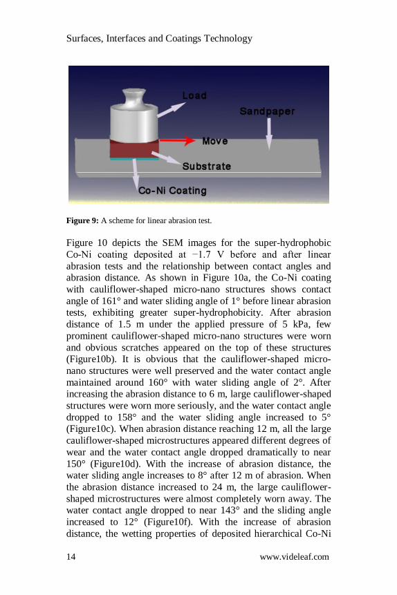
linear abrasion test was conducted, which is shown in Figure 9. The 800 grit SiC sandpaper was placed face up and used as
abrasion surface. The super-hydrophobic Co–Ni coating was
tested under the applied pressure of 5 kPa at a speed of 5 mm/s.
Surfaces, Interfaces and Coatings Technology
14 www.videleaf.com
Figure 9: A scheme for linear abrasion test.
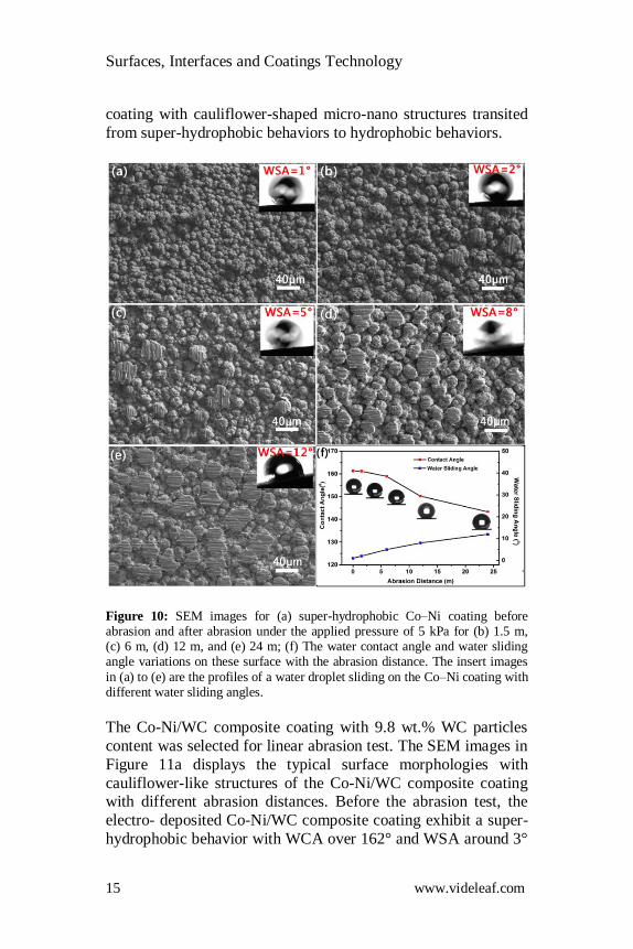
Figure 10 depicts the SEM images for the super-hydrophobic
Co-Ni coating deposited at −1.7 V before and after linear
abrasion tests and the relationship between contact angles and abrasion distance. As shown in Figure 10a, the Co-Ni coating
with cauliflower-shaped micro-nano structures shows contact
angle of 161° and water sliding angle of 1° before linear abrasion tests, exhibiting greater super-hydrophobicity. After abrasion
distance of 1.5 m under the applied pressure of 5 kPa, few
prominent cauliflower-shaped micro-nano structures were worn
and obvious scratches appeared on the top of these structures (Figure10b). It is obvious that the cauliflower-shaped micro-
nano structures were well preserved and the water contact angle
maintained around 160° with water sliding angle of 2°. After increasing the abrasion distance to 6 m, large cauliflower-shaped
structures were worn more seriously, and the water contact angle
dropped to 158° and the water sliding angle increased to 5° (Figure10c). When abrasion distance reaching 12 m, all the large
cauliflower-shaped microstructures appeared different degrees of
wear and the water contact angle dropped dramatically to near
150° (Figure10d). With the increase of abrasion distance, the water sliding angle increases to 8° after 12 m of abrasion. When
the abrasion distance increased to 24 m, the large cauliflower-
shaped microstructures were almost completely worn away. The water contact angle dropped to near 143° and the sliding angle
increased to 12° (Figure10f). With the increase of abrasion
distance, the wetting properties of deposited hierarchical Co-Ni
Surfaces, Interfaces and Coatings Technology
15 www.videleaf.com
coating with cauliflower-shaped micro-nano structures transited
from super-hydrophobic behaviors to hydrophobic behaviors.
Figure 10: SEM images for (a) super-hydrophobic Co–Ni coating before abrasion and after abrasion under the applied pressure of 5 kPa for (b) 1.5 m, (c) 6 m, (d) 12 m, and (e) 24 m; (f) The water contact angle and water sliding angle variations on these surface with the abrasion distance. The insert images
in (a) to (e) are the profiles of a water droplet sliding on the Co–Ni coating with different water sliding angles.
The Co-Ni/WC composite coating with 9.8 wt.% WC particles
content was selected for linear abrasion test. The SEM images in
Figure 11a displays the typical surface morphologies with
cauliflower-like structures of the Co-Ni/WC composite coating with different abrasion distances. Before the abrasion test, the
electro- deposited Co-Ni/WC composite coating exhibit a super-
hydrophobic behavior with WCA over 162° and WSA around 3°
Surfaces, Interfaces and Coatings Technology
16 www.videleaf.com
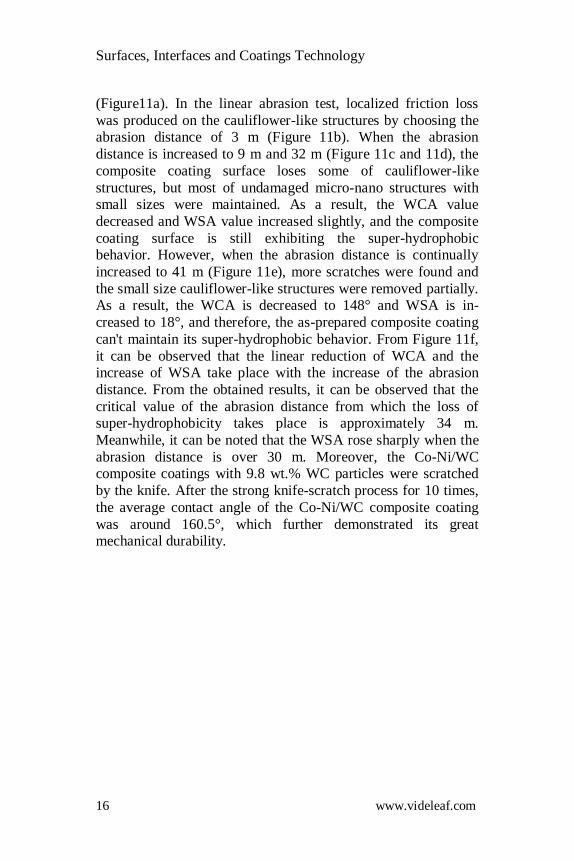
(Figure11a). In the linear abrasion test, localized friction loss
was produced on the cauliflower-like structures by choosing the abrasion distance of 3 m (Figure 11b). When the abrasion
distance is increased to 9 m and 32 m (Figure 11c and 11d), the
composite coating surface loses some of cauliflower-like
structures, but most of undamaged micro-nano structures with small sizes were maintained. As a result, the WCA value
decreased and WSA value increased slightly, and the composite
coating surface is still exhibiting the super-hydrophobic behavior. However, when the abrasion distance is continually
increased to 41 m (Figure 11e), more scratches were found and
the small size cauliflower-like structures were removed partially. As a result, the WCA is decreased to 148° and WSA is in-
creased to 18°, and therefore, the as-prepared composite coating
can't maintain its super-hydrophobic behavior. From Figure 11f,
it can be observed that the linear reduction of WCA and the increase of WSA take place with the increase of the abrasion
distance. From the obtained results, it can be observed that the
critical value of the abrasion distance from which the loss of super-hydrophobicity takes place is approximately 34 m.
Meanwhile, it can be noted that the WSA rose sharply when the
abrasion distance is over 30 m. Moreover, the Co-Ni/WC composite coatings with 9.8 wt.% WC particles were scratched
by the knife. After the strong knife-scratch process for 10 times,
the average contact angle of the Co-Ni/WC composite coating
was around 160.5°, which further demonstrated its great mechanical durability.
Surfaces, Interfaces and Coatings Technology
17 www.videleaf.com
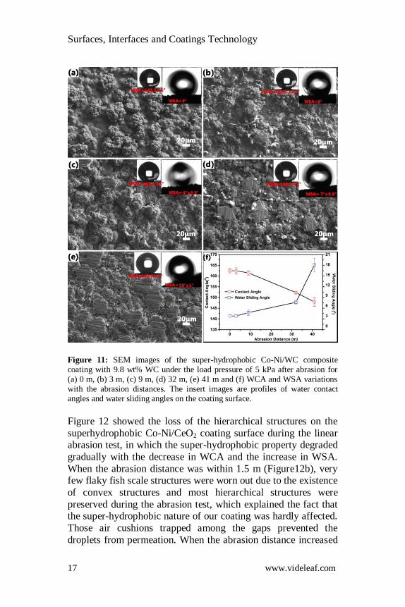
Figure 11: SEM images of the super-hydrophobic Co-Ni/WC composite coating with 9.8 wt% WC under the load pressure of 5 kPa after abrasion for (a) 0 m, (b) 3 m, (c) 9 m, (d) 32 m, (e) 41 m and (f) WCA and WSA variations with the abrasion distances. The insert images are profiles of water contact angles and water sliding angles on the coating surface.
Figure 12 showed the loss of the hierarchical structures on the
superhydrophobic Co-Ni/CeO2 coating surface during the linear abrasion test, in which the super-hydrophobic property degraded
gradually with the decrease in WCA and the increase in WSA.
When the abrasion distance was within 1.5 m (Figure12b), very few flaky fish scale structures were worn out due to the existence
of convex structures and most hierarchical structures were
preserved during the abrasion test, which explained the fact that the super-hydrophobic nature of our coating was hardly affected.
Those air cushions trapped among the gaps prevented the
droplets from permeation. When the abrasion distance increased
Surfaces, Interfaces and Coatings Technology
18 www.videleaf.com
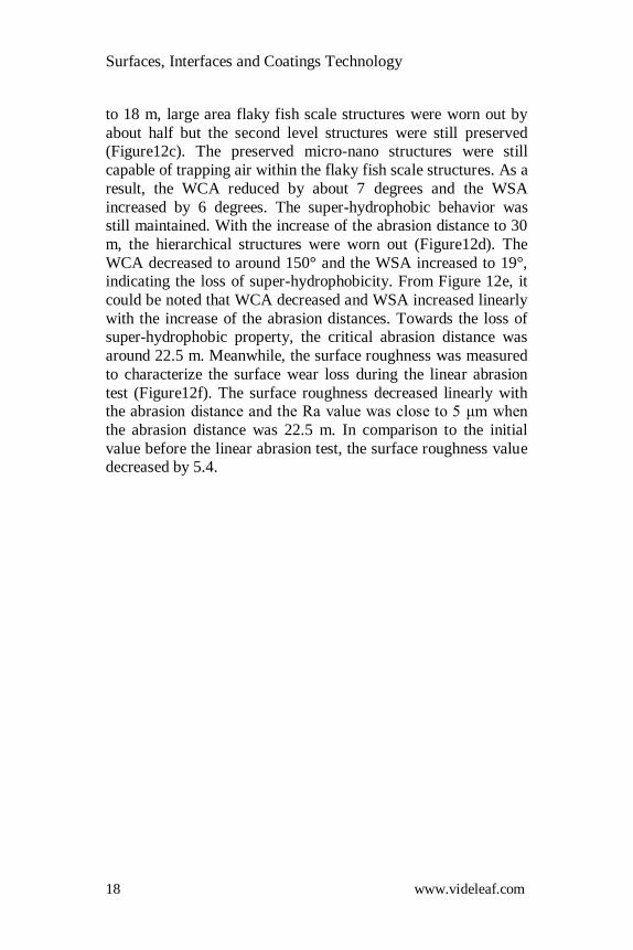
to 18 m, large area flaky fish scale structures were worn out by
about half but the second level structures were still preserved (Figure12c). The preserved micro-nano structures were still
capable of trapping air within the flaky fish scale structures. As a
result, the WCA reduced by about 7 degrees and the WSA
increased by 6 degrees. The super-hydrophobic behavior was still maintained. With the increase of the abrasion distance to 30
m, the hierarchical structures were worn out (Figure12d). The
WCA decreased to around 150° and the WSA increased to 19°, indicating the loss of super-hydrophobicity. From Figure 12e, it
could be noted that WCA decreased and WSA increased linearly
with the increase of the abrasion distances. Towards the loss of super-hydrophobic property, the critical abrasion distance was
around 22.5 m. Meanwhile, the surface roughness was measured
to characterize the surface wear loss during the linear abrasion
test (Figure12f). The surface roughness decreased linearly with the abrasion distance and the Ra value was close to 5 μm when
the abrasion distance was 22.5 m. In comparison to the initial
value before the linear abrasion test, the surface roughness value decreased by 5.4.
Surfaces, Interfaces and Coatings Technology
19 www.videleaf.com
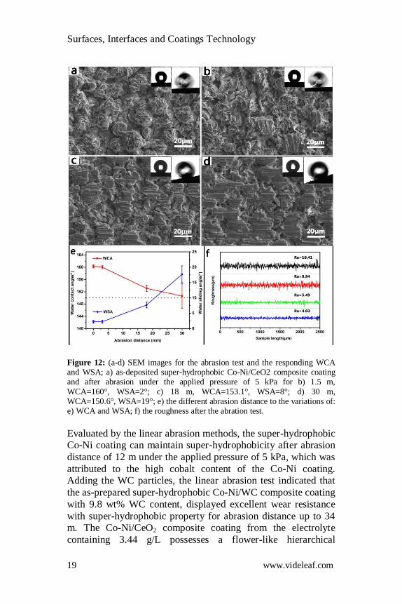
Figure 12: (a-d) SEM images for the abrasion test and the responding WCA and WSA; a) as-deposited super-hydrophobic Co-Ni/CeO2 composite coating and after abrasion under the applied pressure of 5 kPa for b) 1.5 m,
WCA=160°, WSA=2°; c) 18 m, WCA=153.1°, WSA=8°; d) 30 m, WCA=150.6°, WSA=19°; e) the different abrasion distance to the variations of: e) WCA and WSA; f) the roughness after the abration test.
Evaluated by the linear abrasion methods, the super-hydrophobic Co-Ni coating can maintain super-hydrophobicity after abrasion
distance of 12 m under the applied pressure of 5 kPa, which was
attributed to the high cobalt content of the Co-Ni coating. Adding the WC particles, the linear abrasion test indicated that
the as-prepared super-hydrophobic Co-Ni/WC composite coating
with 9.8 wt% WC content, displayed excellent wear resistance
with super-hydrophobic property for abrasion distance up to 34 m. The Co-Ni/CeO2 composite coating from the electrolyte
containing 3.44 g/L possesses a flower-like hierarchical
Surfaces, Interfaces and Coatings Technology
20 www.videleaf.com
structures, displaying a super-hydrophobic behavior after the
modification by PFTEOS. More importantly, excellent mechanical durability with critical abrasion distance of 22.5 m is
achieved under a 5 kPa fixed normal pressure in the liner
abrasion test before the loss of super-hydrophobicity. We have
found that some features were of vital importance for the wear resistance of superhydrophobic coatings, such as the micro–nano
hierarchical structures and microhardness. As indicated by the
results, microhardness and roughness showed a positive correlation with the abrasion distance of the superhydrophobic
composite coatings. To improve the wear resistance of the
superhydrophobic coating, its microhardness was improved by adding second-phase particles, which was proved effective
through our works.
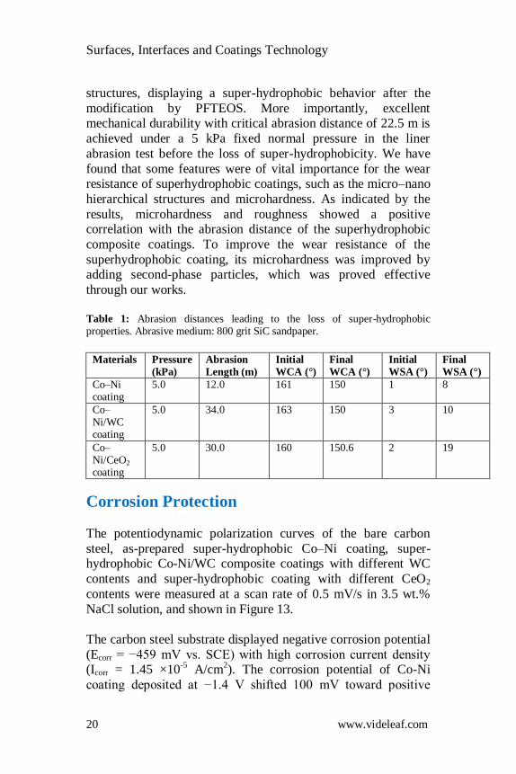
Table 1: Abrasion distances leading to the loss of super-hydrophobic properties. Abrasive medium: 800 grit SiC sandpaper.
Materials Pressure
(kPa)
Abrasion
Length (m)
Initial
WCA (°)
Final
WCA (°)
Initial
WSA (°)
Final
WSA (°)
Co–Ni coating
5.0 12.0 161 150 1 8
Co–Ni/WC coating
5.0 34.0 163 150 3 10
Co–Ni/CeO2 coating
5.0 30.0 160 150.6 2 19
Corrosion Protection
The potentiodynamic polarization curves of the bare carbon
steel, as-prepared super-hydrophobic Co–Ni coating, super-hydrophobic Co-Ni/WC composite coatings with different WC
contents and super-hydrophobic coating with different CeO2
contents were measured at a scan rate of 0.5 mV/s in 3.5 wt.%
NaCl solution, and shown in Figure 13.
The carbon steel substrate displayed negative corrosion potential
(Ecorr = −459 mV vs. SCE) with high corrosion current density (Icorr = 1.45 ×10
-5 A/cm
2). The corrosion potential of Co-Ni
coating deposited at −1.4 V shifted 100 mV toward positive
Surfaces, Interfaces and Coatings Technology
21 www.videleaf.com
direction compared with carbon steel with lower corrosion
current density of 1.50×10⁻⁶ A/cm
2. For the super-hydrophobic
Co–Ni coating deposited at −1.7 V, the corrosion potential and
corrosion current density are −303 mV and 5.87×10⁻⁷
A/cm2
respectively. The corrosion current density of as-prepared super-
hydrophobic Co-Ni coating was 20 times lower than that of bare carbon steel substrate, demonstrating the significantly improved
anti-corrosion performance of the super-hydrophobic Co-Ni
coating with cauliflower-shaped micro-nano structures.
Generally, the positive shift of the corrosion potential and the
low corrosion current density are a signature of a better corrosion resistance. As shown in Figure 13b, the Co-Ni/WC composite
coatings show a better corrosion resistance compared both to the
carbon steel substrate and the super-hydrophobic Co-Ni coating
according to these characteristics. The anodic polarization current density measured for super-hydrophobic Co-Ni/WC
composite coating with the WC particles content of 9.8 wt.%
(Icorr=1.29×10⁻⁷
A/cm2) decreases by about two orders of
magnitude compared to bare carbon steel (Icorr=1.45×10⁻⁵
A/cm2).
In addition, although the composite coating with the WC
particles content of 19.1 wt.% exhibits hydrophobic property with WCA of 145º, its corrosion current density (Icorr=1.78×10
-6
A/cm2) was one order of magnitude lower than that of the bare
carbon steel. Compared with the carbon steel substrate, both the
anodic and cathodic branches of the as-prepared coatings show lower current density, indicating that the as-prepared super-
hydrophobic Co-Ni/WC composite coating provides great
corrosion protection performance.
As shown in Figure 13c, for the super-hydrophobic Co-Ni/CeO2
composite coating (1.72 g/L CeO2 and 3.44 g/L CeO2), the
corrosion potentials shift positively about 109 mV and 142 mV respectively. Due to the adding of CeO2 particles, the corrosion
probability of the as-prepared super-hydrophobic coatings
decreases. The as-prepared super-hydrophobic coatings electrodeposited with the CeO2 particles of 1.72 g/L and 3.44 g/L
exhibited a two orders of magnitude reduction in corrosion rate,
which could be attributed to their super-hydrophobicity that the trapped air as a barrier decreased the solution/solid contact area
Surfaces, Interfaces and Coatings Technology
22 www.videleaf.com
effectively. However, with the increasing of micro-nano CeO2
particles to 6.88 g/L, corrosion potential shift negatively a little and the corrosion current density (icorr) was smaller than those of
the aforementioned composite coatings, which could be
attributed to the formation of holes based on the difficulty of co-
electrodeposition under the deposition conditions of large amount of CeO2 particles in the mixed solution.
These results clearly show that the as-prepared super-hydrophobic Co-Ni coating, super-hydrophobic Co-Ni/WC
composite coatings and super-hydrophobic Co-Ni/CeO2
composite coatings exhibit higher corrosion resistance than carbon steel substrate. The air entrapped in the cauliflower like
structures can prevent the super-hydrophobic composite coating
from being wetted by the corrosion medium through the limited
solid contact area, endowing the coating larger charge transfer resistance and lower corrosion rate, and then better corrosion
protection performance [29].
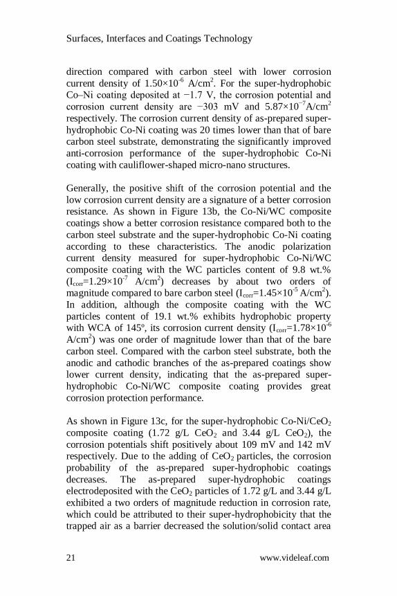
Figure 13: Potentiodynamic polarization curves of (a) Super-hydrophobic Co–Ni coating, (b) Super-hydrophobic Co-Ni/WC composite coatings with different WC contents and (c) Super-hydrophobic coating with different CeO2
contents in 3.5 wt% NaCl aqueous solution at the scan rate of 0.5 mV/s.
Table 2: Derived results from the potentiodynamic polarization measurements.
Sample Ecorr
(mV) Icorr (A/cm2)
Corrosion rate(mm/a)
Bare carbon steel -459.4 1.45 ×10⁻⁵ 0.162
Superhydrophobic Co-Ni coating -303.3 5.87×10⁻⁷ 0.0066
Superhydrophobic Co-Ni/WC coating -286.3 2.48×10⁻⁹ 0.000028
Superhydrophobic Co-Ni/CeO2 coating
-316.9 1.24×10⁻⁷ 0.0014
Surfaces, Interfaces and Coatings Technology
23 www.videleaf.com
Long-Term Durability
The long-term durability for two kinds Co-Ni based robust coatings, Co-Ni super-hydrophobic coating and Co-Ni/WC
super-hydrophobic coating, was analyzed by immersion test in
3.5 wt.% NaCl solution. The immersion test displayed that two
kinds of robust super-hydrophobic coatings have long-term durability, where the Co-Ni super-hydrophobic coating loses
super-hydrophobicity after immersion for 20 days and the critical
immersion time of Co-Ni/WC super-hydrophobic coating was 12 days, respectively. The loss of super-hydrophobicity could be
attributed to the corrosion damage of the micro-nanostructures
on the coating and the decomposition of low surface energy
materials. In the early stage of immersion, the decomposition of hydrophobic groups occurred firstly. In the later stage, it
appeared as corrosion damage of micro-nano structures on the
coatings.
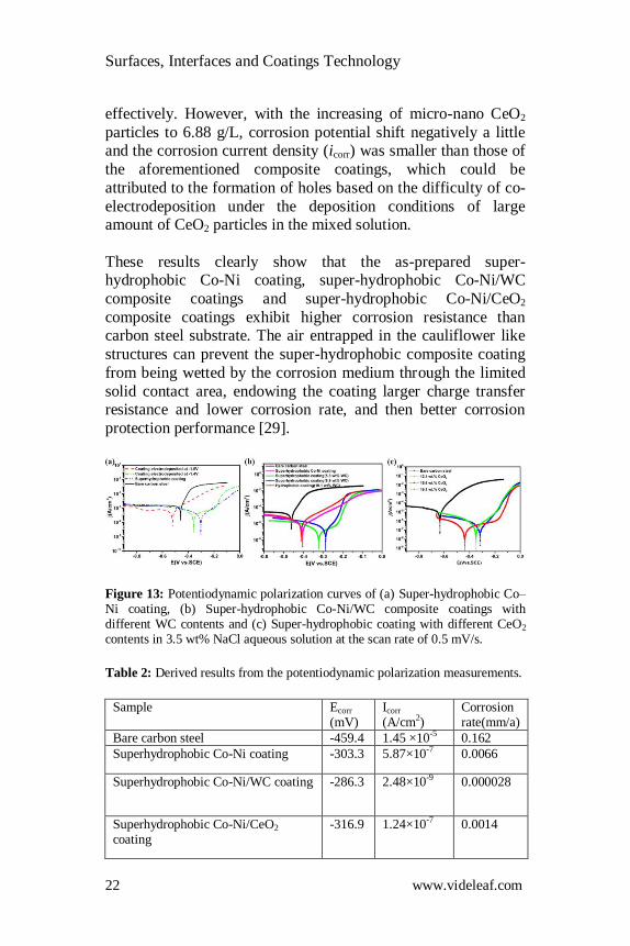
Figure 14: Wettability variations (WCA, WSA) with immersion time of (a) Co-Ni superhydrophobic coating and (b) Co-Ni/WCsuperhydrophobic composite coating.
Conclusion
The Co-Ni based composite coatings were prepared on carbon steel by the co-electrochemical deposition process by adding
different micro-nano particles in the mixed solution. During the
modification process, the PFTEOS molecules can induce the transit from super-hydrophilicity to super-hydrophobicity of the
as-prepared composite coatings. The linear abrasion test revealed
that the super-hydrophobic Co-Ni based composite coatings
Surfaces, Interfaces and Coatings Technology
24 www.videleaf.com
displayed excellent mechanical durability at 5 kPa load pressure
and Co-Ni, Co-Ni/WC, Co-Ni/CeO2 superhydrophobic coating can keep their super-hydrophobicity for the abrasion distance of
12 m, 34 m, 22.5 m, respectively. The higher abrasion resistance
of the deposited Co-Ni based composite coating was attributed to
the combination of micro-nano particles addition with high cobalt content inside the coating. Moreover, the corrosion
current density of the super-hydrophobic Co-Ni based coating
was decreased by more than two orders of magnitude compared to that of bare carbon steel, exhibiting great corrosion protection.
With the robust mechanical durability, the as-prepared super-
hydrophobic Co-Ni based composite coating could be excellent alternative technique for real applications in the future.
References
1. S Esmailzadeh, S Khorsand, K Raeissi, F Ashrafizadeh. Microstructural evolution and corrosion resistance of super-
hydrophobic electrodeposited nickel films. Surf. Coatings
Technol. 2015; 283: 337–346. 2. D Zhang, L Wang, H Qian, X Li. Superhydrophobic surfaces
for corrosion protection: a review of recent progresses and
future directions. J. Coatings Technol. Res. 2016; 13: 11–29.
3. P Eberle, MK Tiwari, T Maitra, D Poulikakos. Rational nanostructuring of surfaces for extraordinary icephobicity.
Nanoscale. 2014; 6: 4874–4881.
4. T Maitra, MK Tiwari, C Antonini, P Schoch, S Jung, et al. On the nanoengineering of superhydrophobic and
impalement resistant surface textures below the freezing
temperature. Nano Lett. 2014; 14: 172–182. 5. Q Ma, H Cheng, AG Fane, R Wang, H Zhang. Recent
Development of Advanced Materials with Special
Wettability for Selective Oil/Water Separation. Small. 2016;
12: 2186–2202. 6. X Yao, Y Song, L Jiang. Applications of bio-inspired special
wettable surfaces, Adv. Mater. 2011; 23: 719–734.
7. X Yanpeng, A Taleb, P Jegou. Electrodeposition of cobalt films with an oriented fir tree-like morphology with
adjustable wetting properties using a self-assembled gold
nanoparticle modified HOPG electrode. J. Mater. Chem. A.
Surfaces, Interfaces and Coatings Technology
25 www.videleaf.com
2013; 1: 11580–11588.
8. C Peng, Z Chen, MK Tiwari. All-organic superhydrophobic coatings with mechanochemical robustness and liquid
impalement resistance. Nat. Mater. 2018; 17: 355–360.
9. HC Barshilia, N Gupta. Superhydrophobic
polytetrafluoroethylene surfaces with leaf-like micro-protrusions through Ar + O2 plasma etching process.
Vacuum. 2014; 99: 42–48.
10. S Rezaei, I Manoucheri, R Moradian, B Pourabbas. One-step chemical vapor deposition and modification of silica
nanoparticles at the lowest possible temperature and
superhydrophobic surface fabrication. Chem. Eng. J. 2014; 252: 11–16.
11. WH Huang, CS Lin. Robust superhydrophobic transparent
coatings fabricated by a low-temperature sol-gel process.
Appl. Surf. Sci. 2014; 305: 702–709. 12. W Xi, Z Qiao, C Zhu, A Jia, M Li. The preparation of lotus-
like super-hydrophobic copper surfaces by electroplating.
Appl. Surf. Sci. 2009; 255: 4836–4839. 13. F Su, K Yao. Facile fabrication of superhydrophobic surface
with excellent mechanical abrasion and corrosion resistance
on copper substrate by a novel method. ACS Appl. Mater. Interfaces. 2014; 6: 8762–8770.
14. G Zhao, Y Xue, Y Huang, Y Ye, FC Walsh, et al. One-step
electrodeposition of a self-cleaning and corrosion resistant
Ni/WS2 superhydrophobic surface, RSC Adv. 2016; 6: 59104–59112.
15. J Zhou, G Zhao, J Li, J Chen, S Zhang, et al. Electroplating
of non-fluorinated superhydrophobic Ni/WC/WS2 composite coatings with high abrasive resistance. Appl. Surf.
Sci. 2019; 487: 1329–1340.
16. RP Silva, S Eugénio, TM Silva, MJ Carmezim, MF
Montemor. Fabrication of three-dimensional dendritic Ni-Co films by electrodeposition on stainless steel substrates. J.
Phys. Chem. C. 2012; 116: 22425–22431.
17. Y Xue, S Wang, G Zhao, A Taleb, Y Jin. Fabrication of Ni-Co coating by electrochemical deposition with high super-
hydrophobic properties for corrosion protection. Surf. Coat.
Technol. 2019; 363: 352–361. 18. T Verho, C Bower, P Andrew, S Franssila, O Ikkala, et al.
Surfaces, Interfaces and Coatings Technology
26 www.videleaf.com
Mechanically Durable Superhydrophobic Surfaces. Adv.
Mater. 2011; 23: 673–678. 19. D Wang, Q Sun, MJ Hokkanen, C Zhang, FY Lin, et al.
Design of robust superhydrophobic surfaces. Nature. 2020;
582: 55–59.
20. Y Xue, S Wang, P Bi, G Zhao, Y Jin. Super-hydrophobic Co-Ni coating with high abrasion resistance prepared by
electrodeposition. Coatings. 2019; 9: 1–14.
21. S Wang, Y Xue, C Ban, Y Xue, A Taleb, et al. Fabrication of robust tungsten carbide particles reinforced Co–Ni super-
hydrophobic composite coating by electrochemical
deposition, Surf. Coatings Technol. 2020; 385: 125390. 22. Y Xue, S Wang, P Bi, G Zhao, Y Jin. Super-hydrophobic Co-
Ni coating with high abrasion resistance prepared by
electrodeposition. Coatings. 2019; 9.
23. G Azimi, R Dhiman, HM Kwon, AT Paxson, KK Varanasi. Hydrophobicity of rare-earth oxide ceramics. Nat. Mater.
2013; 12: 315–320.
24. Y Xue, S Wang, Y Xue, L Cao, M Nie, et al. Robust Self-Cleaning and Marine Anticorrosion Super-Hydrophobic Co–
Ni/CeO2 Composite Coatings. Adv. Eng. Mater. 2020; 22.
25. C Jeong, CH Choi. Single-step direct fabrication of pillar-on-pore hybrid nanostructures in anodizing aluminum for
superior superhydrophobic efficiency. ACS Appl. Mater.
Interfaces. 2012; 4: 842–848.
26. T Darmanin, E Taffi, D Givenchy, S Amigoni, F Guittard. Superhydrophobic Surfaces by Electrochemical Processes.
Adv. Mater. 2013; 25: 1378–1394.
27. Y Tian, B Su, L Jiang. Interfacial Material System Exhibiting Superwettability. Adv. Mater. 2014; 26: 6872–6897.
28. X Tian, T Verho, RHA Ras. Moving superhydrophobic
surfaces toward real-world applications, Science (80-). 2016;
352: 142–143. 29. P Bi, H Li, G Zhao, M Ran, L Cao, et al. Robust super-
hydrophobic coating prepared by electrochemical surface
engineering for corrosion protection. Coatings. 2019; 9.
Related Documents