Fabrication, Modelling and Application of Conductive Polymer Composites by Aaron David Price A thesis submitted in conformity with the requirements for the degree of Doctor of Philosophy Graduate Department of Mechanical and Industrial Engineering University of Toronto Copyright © 2012 by Aaron David Price

Welcome message from author
This document is posted to help you gain knowledge. Please leave a comment to let me know what you think about it! Share it to your friends and learn new things together.
Transcript
Fabrication, Modelling and Application of Conductive
Polymer Composites
by
Aaron David Price
A thesis submitted in conformity with the requirementsfor the degree of Doctor of Philosophy
Graduate Department of Mechanical and Industrial Engineering
University of Toronto
Copyright © 2012 by Aaron David Price

Abstract
Fabrication, Modelling and Application of Conductive Polymer Composites
Aaron David Price
Doctor of Philosophy
Graduate Department of Mechanical and Industrial Engineering
University of Toronto
2012
Electroactive polymers (EAP) are an emerging branch of smart materials that possess
the capability to change shape in the presence of an electric field. Opportunities for the
advancement of knowledge were identified in the branch of EAP consisting of inherently
electrically conductive polymers. This dissertation explores methods by which the unique
properties of composite materials having conductive polymers as a constituent may be
exploited.
Chapter 3 describes the blending of polyaniline with conventional thermoplastics.
Processing these polyblends into foams yielded a porous conductive material. The effect
of blend composition and processing parameters on the resulting porous morphology and
electrical conductivity was investigated. These findings represent the first systematic
study of porous conductive polymer blends.
In Chapter 4, multilayer electroactive polymer actuators consisting of polypyrrole
films electropolymerized on a passive polymer membrane core were harnessed as actu-
ators. The membrane is vital in the transport of ionic species and largely dictates the
stiffness of the layered configuration. The impact of the mechanical properties of the
membrane on the actuation response of polypyrrole-based trilayer bending actuators was
investigated. Candidate materials with distinct morphologies were identified and their
mechanical properties were evaluated. These results indicated that polyvinylidene diflu-
oride membranes were superior to the other candidates. An electrochemical synthesis
ii

procedure was proposed, and the design of a novel polymerization vessel was reported.
These facilities were utilized to prepare actuators under a variety of synthesis conditions
to investigate the impact of conductive polymer morphology on the electromechanical re-
sponse. Characterization techniques were implemented to quantitatively assess physical
and electrochemical properties of the layered composite.
Chapter 5 proposes a new unified multiphysics model that captures the electroactive
actuation response inherent to conductive polymer trilayer actuators. The main contri-
bution of this investigation was the proposal and development of a new hybrid model that
unifies concepts from charge transport and electrochemomechanical models. The output
of the proposed model was compared with published data and shown to be accurate to
within 10%.
Finally, Chapter 6 demonstrated the application of these materials for use as precision
mirror positioners in adaptive optical systems.
iii

Extended Abstract
Fabrication, Modelling and Application of Conductive Polymer Composites
Aaron David Price
Doctor of Philosophy
Graduate Department of Mechanical and Industrial Engineering
University of Toronto
2012
Electroactive polymers (EAP) are an emerging branch of smart materials that possess the
unique capability to change shape in the presence of an electric field. These polymers are
categorized according to their microstructural properties as electric, ionic or molecular
and can be used in a variety of applications ranging from high-performance textiles
to self-repairing components in the transportation industry. Recent advances in the
biotechnology industry have revealed enormous potential for the application of EAP for
biomedical use.
At the onset of the research programme presented herein, preliminary research effort
was allocated to the synthesis of a variety of EAP materials including carbon nanotube
sheets, conducting polymer fibres and films, and ionomeric polymer-metal composites.
From these initial steps, it was determined that several opportunities for the advancement
of knowledge existed in the particular branch of EAP consisting of inherently electrically
conductive polymers, as their relative youth corresponded with an incomplete under-
standing of the field.
This dissertation explores methods by which the unique properties of composite ma-
terials having conductive polymers as a constituent may be exploited. These approaches
are segregated into four aspects: blending of conducting polymers and conventional ther-
moplastics to achieve novel low-density polymeric composites, fabrication techniques and
characterization methods for conducting polymer trilayer actuators, multiphysics finite
iv

element modelling of these actuators, and finally a demonstration of their implemen-
tation in a real engineering system. Each of these investigations represents an original
contribution to knowledge of conducting polymer composites.
Chapter 3, Porous composite blends of conductive polymers forms the basis of two
distinct published journal papers in Synthetic Metals and Cellular Polymers. This chap-
ter describes how the conductive polymer polyaniline was blended with conventional
industrial thermoplastics in order to obtain an electrically conductive polymer blend
with satisfactory mechanical properties. Processing these polyblends into foams yielded
a porous conductive material that exhibited immense application potential (such as dy-
namic separation media and low-density electrostatic discharge protection packaging, for
example). In this chapter, the morphology of a thermally-processable blend consist-
ing of an electrically conductive polyaniline-dodecylbenzene sulfonic acid complex and
poly(methyl methacrylate) was explored using a two-phase batch foaming setup. The ef-
fect of blend composition and processing parameters on the resulting porous morphology
was investigated. The impact of the underlying microstructure and blend composition
on the frequency dependent electrical conductivity was elucidated using multiple linear
regression, and a model was proposed. Finally, dielectric analysis was utilized to identify
the critical dispersion frequency of an unfoamed blend composition near the percolation
threshold. These findings represent the first systematic study of porous conductive poly-
mer blends and reveal a tremendous opportunity for a vast array of novel low-density
electrically conductive polymeric materials.
Chapter 4, Fabrication and characterization of polypyrrole trilayer actuators provides
the basis for a manuscript published in Cellular Plastics. In this chapter, multilayer
electroactive polymer actuators consisting of polypyrrole films electropolymerized on a
passive polymer membrane core were harnessed as actuators. It was shown that the mem-
brane plays a vital role in the transport of ionic species and largely dictates the stiffness
of the layered configuration, yet in past studies the specification of the membrane re-
v

mained arbitrary. Here, the impact of the mechanical properties of the membrane on
the actuation response of polypyrrole-based trilayer bending actuators was investigated.
Candidate materials with distinct morphologies were identified and include polyvinyli-
dene difluoride, Nylon, and nitrocellulose. The quasistatic stress-strain response and
the frequency dependent viscoelastic nature of the candidates were then evaluated. On
the basis of mechanical properties, these results indicated that polyvinylidene difluoride
membranes were superior to the other candidates for application as trilayer actuator
cores. An effective electrochemical synthesis procedure was also proposed, and the re-
fined design of a novel polymerization vessel was reported. These facilities were then
utilized to prepare bis(trifluoromethane)sulfonimide doped polypyrrole actuators with
polyvinylidene difluoride cores and Nylon cores under a variety of synthesis conditions
to investigate the impact of conductive polymer morphology on the electromechanical
actuation response. Characterization techniques were also developed and implemented
to quantitatively assess physical and electrochemical properties of the layered composite.
Chapter 5, Modelling the polypyrrole trilayer actuation mechanism proposes a new
unified multiphysics model that captures the electroactive actuation response inherent
to conductive polymer trilayer actuators. The chapter reviewed the existing conduc-
tive polymer actuator modelling approaches, and a major deficiency was identified in
that these models are based on specimen-specific properties, which must be individually
characterized a priori and/or monitored in situ. The main contribution of this investiga-
tion was the remediation of this deficiency through the proposal and development of a
new hybrid model that unifies concepts from charge transport models and electrochemo-
mechanical approaches. The output of the proposed model was compared with published
data and shown to be accurate to within 10% over a useful range of input voltage levels.
Finally, Chapter 6, Application of electroactive polymers in optical systems demon-
strated the application of these materials for use as precision mirror positioners in adap-
tive optical systems.
vi

The ideal engineer is a composite . . . He is not a scientist, he is not a mathe-
matician, he is not a sociologist or a writer; but he may use the knowledge and
techniques of any or all of these disciplines in solving engineering problems.
– N. W. Dougherty
Professor of Civil Engineering
University of Tennessee, 1955
vii
Acknowledgements
Financial support for my studies was generously provided by NSERC Canada, DuPont
Canada Inc., Canada Foundation for Innovation, Canada Research Chairs Program, the
Government of Ontario: Ministry of Research and Innovation, and the University of
Toronto.
Thanks to the members of my Examination Committee, and in particular to Profs. Jan
Spelt and Ridha Ben Mrad for their insightful guidance throughout the duration of the
project. Thanks also to Prof. Ben Amara for suggesting the opportunity for the optical
application of electroactive polymers and for facilitating the exploration of electroactive
polymers in adaptive optical components.
Special thanks to my thesis supervisor Prof. Hani Naguib for his enduring patience
and forthright advice, for giving me the opportunity to interact with the global leaders of
the electroactive polymer community, for awarding me the freedom to pursue the ideas I
thought were most interesting, and for enforcing his policy regarding journal publication
frequency.
Finally, thank you to my past and present colleagues in the Smart and Adaptive
Polymers Laboratory, my dearest friends, and especially my family. Thanks to my loving
wife Jennifer, who always had faith in me through thick and thin, across international
borders and multiple time zones. I owe special gratitude to my Mother for inspiring my
inquisitive nature, and to my late Father for instilling in me a spirit of perseverance in
the face of adversity, without which this work would not have been possible. You’ve all
supported me in one way or another along the way, and for that I am eternally grateful.
Thank you all.
viii

Contents
1 Introduction 1
1.1 Objectives . . . . . . . . . . . . . . . . . . . . . . . . . . . . . . . . . . . 2
1.2 Major contributions . . . . . . . . . . . . . . . . . . . . . . . . . . . . . . 5
1.3 Organization of the thesis . . . . . . . . . . . . . . . . . . . . . . . . . . 6
List of references . . . . . . . . . . . . . . . . . . . . . . . . . . . . . . . . . . 7
2 Exploratory work: synthesis of ionic EAP 9
2.1 Summary of relevant exploratory work . . . . . . . . . . . . . . . . . . . 10
2.2 Brief theoretical background . . . . . . . . . . . . . . . . . . . . . . . . . 10
2.2.1 Structure and composition of IPMC actuators . . . . . . . . . . . 10
2.2.2 IPMC actuation mechanism . . . . . . . . . . . . . . . . . . . . . 11
2.2.3 IPMC modelling . . . . . . . . . . . . . . . . . . . . . . . . . . . 12
2.2.4 Polyaniline fibre . . . . . . . . . . . . . . . . . . . . . . . . . . . . 14
2.3 Experimental results . . . . . . . . . . . . . . . . . . . . . . . . . . . . . 16
2.3.1 PAni-coated IPMC . . . . . . . . . . . . . . . . . . . . . . . . . . 16
2.3.2 Polyaniline fibre . . . . . . . . . . . . . . . . . . . . . . . . . . . . 18
2.4 Electrical conductivity and actuation mechanisms . . . . . . . . . . . . . 20
2.4.1 Electrical conductivity in conjugated polymers . . . . . . . . . . . 20
2.4.2 Actuation mechanism in PPy . . . . . . . . . . . . . . . . . . . . 23
ix

2.5 Chapter summary . . . . . . . . . . . . . . . . . . . . . . . . . . . . . . . 26
List of references . . . . . . . . . . . . . . . . . . . . . . . . . . . . . . . . . . 27
3 Porous composite blends of conductive polymers 33
3.1 Introduction . . . . . . . . . . . . . . . . . . . . . . . . . . . . . . . . . . 34
3.2 Batch foaming process . . . . . . . . . . . . . . . . . . . . . . . . . . . . 35
3.3 Experimental methodology . . . . . . . . . . . . . . . . . . . . . . . . . . 37
3.3.1 Blended sample preparation . . . . . . . . . . . . . . . . . . . . . 37
3.3.2 Microcellular processing . . . . . . . . . . . . . . . . . . . . . . . 38
3.3.3 Characterization of porous morphology . . . . . . . . . . . . . . . 38
3.3.4 Characterization of dielectric properties . . . . . . . . . . . . . . . 39
3.4 Results and discussion . . . . . . . . . . . . . . . . . . . . . . . . . . . . 40
3.4.1 Samples . . . . . . . . . . . . . . . . . . . . . . . . . . . . . . . . 40
3.4.2 Porous morphology . . . . . . . . . . . . . . . . . . . . . . . . . . 41
3.4.3 Dielectric properties . . . . . . . . . . . . . . . . . . . . . . . . . 48
3.5 Chapter summary . . . . . . . . . . . . . . . . . . . . . . . . . . . . . . . 52
List of references . . . . . . . . . . . . . . . . . . . . . . . . . . . . . . . . . . 52
4 Fabrication and characterization of polypyrrole trilayer actuators 57
4.1 Introduction . . . . . . . . . . . . . . . . . . . . . . . . . . . . . . . . . . 58
4.2 Review of ICP actuator technology . . . . . . . . . . . . . . . . . . . . . 59
4.2.1 Evolution of the conducting polymer trilayer actuator . . . . . . . 60
4.2.2 Polypyrrole synthesis . . . . . . . . . . . . . . . . . . . . . . . . . 61
4.3 Mechanical analysis of porous core materials . . . . . . . . . . . . . . . . 63
4.4 Actuator fabrication method . . . . . . . . . . . . . . . . . . . . . . . . . 65
4.5 Characterization of trilayer actuators . . . . . . . . . . . . . . . . . . . . 69
4.5.1 Analysis of trilayer microstructure . . . . . . . . . . . . . . . . . . 69
4.5.2 Electromechanical response . . . . . . . . . . . . . . . . . . . . . 70
x

4.6 Chapter summary . . . . . . . . . . . . . . . . . . . . . . . . . . . . . . . 76
List of references . . . . . . . . . . . . . . . . . . . . . . . . . . . . . . . . . . 78
5 Modelling the polypyrrole trilayer actuation mechanism 84
5.1 Introduction . . . . . . . . . . . . . . . . . . . . . . . . . . . . . . . . . . 85
5.2 Review of existing CP actuator modelling approaches . . . . . . . . . . . 85
5.2.1 Diffusive Elastic Metal model . . . . . . . . . . . . . . . . . . . . 86
5.2.2 Numerical methods: thermal expansion analogues . . . . . . . . . 87
5.2.3 Electrochemomechanical models . . . . . . . . . . . . . . . . . . . 87
5.2.4 Charge transport models . . . . . . . . . . . . . . . . . . . . . . . 90
5.3 Design considerations for trilayer actuators . . . . . . . . . . . . . . . . . 91
5.3.1 Force output at equilibrium . . . . . . . . . . . . . . . . . . . . . 92
5.3.2 Displacement capability . . . . . . . . . . . . . . . . . . . . . . . 92
5.3.3 Time response . . . . . . . . . . . . . . . . . . . . . . . . . . . . . 93
5.3.4 Comparison with other actuation technologies . . . . . . . . . . . 93
5.4 A new unified multiphysics finite element model . . . . . . . . . . . . . . 93
5.4.1 Model identification . . . . . . . . . . . . . . . . . . . . . . . . . . 94
5.4.2 Charge transport . . . . . . . . . . . . . . . . . . . . . . . . . . . 95
5.4.3 Solid mechanics . . . . . . . . . . . . . . . . . . . . . . . . . . . . 104
5.5 Model validation . . . . . . . . . . . . . . . . . . . . . . . . . . . . . . . 108
5.6 Chapter summary . . . . . . . . . . . . . . . . . . . . . . . . . . . . . . . 109
List of references . . . . . . . . . . . . . . . . . . . . . . . . . . . . . . . . . . 110
6 Application of electroactive polymers in optical systems 114
6.1 EAP actuators and adaptive optics . . . . . . . . . . . . . . . . . . . . . 115
6.1.1 Conducting polymer actuators . . . . . . . . . . . . . . . . . . . . 116
6.1.2 Stroke requirement for piston-tilt mirrors . . . . . . . . . . . . . . 117
6.2 Fabrication method for trilayer EAP actuators . . . . . . . . . . . . . . . 118
xi

6.3 Design of an EAP piston-tilt mirror . . . . . . . . . . . . . . . . . . . . . 118
6.4 Experimental performance characterization . . . . . . . . . . . . . . . . . 122
6.5 Chapter summary . . . . . . . . . . . . . . . . . . . . . . . . . . . . . . . 127
List of references . . . . . . . . . . . . . . . . . . . . . . . . . . . . . . . . . . 127
7 Concluding remarks 130
7.1 Summary of conclusions . . . . . . . . . . . . . . . . . . . . . . . . . . . 130
7.2 Summary of contributions . . . . . . . . . . . . . . . . . . . . . . . . . . 132
7.3 Scholarly publications associated with this thesis . . . . . . . . . . . . . . 134
7.3.1 Refereed journal publications . . . . . . . . . . . . . . . . . . . . 134
7.3.2 Refereed conference papers published in proceedings . . . . . . . . 135
7.3.3 Conference presentations . . . . . . . . . . . . . . . . . . . . . . . 136
7.3.4 Poster presentations . . . . . . . . . . . . . . . . . . . . . . . . . 137
7.4 Recommendations for future research . . . . . . . . . . . . . . . . . . . . 137
Appendices
A List of acronyms and symbols 140
B Software code listing 146
B.1 COMSOL Multiphysics® implementation of UMP-FEM . . . . . . . . . 146
xii

List of Tables
2.1 Experimental parameters for spinning of PAni fibres . . . . . . . . . . . . 18
3.1 Summary of pore morphology characteristics. . . . . . . . . . . . . . . . 44
4.1 Tip deflections as function of electric potential . . . . . . . . . . . . . . . 73
5.1 Summary of model parameters. . . . . . . . . . . . . . . . . . . . . . . . 107
xiii

List of Figures
1.1 Road-map of studied EAP technologies . . . . . . . . . . . . . . . . . . . 3
2.1 PAni fibre spinning procedure . . . . . . . . . . . . . . . . . . . . . . . . 15
2.2 PAni fibre spinning apparatus . . . . . . . . . . . . . . . . . . . . . . . . 16
2.3 PAni surface coating on IPMC . . . . . . . . . . . . . . . . . . . . . . . . 17
2.4 Hybrid PAni-IPMC actuator performance . . . . . . . . . . . . . . . . . 17
2.5 PAni fibre . . . . . . . . . . . . . . . . . . . . . . . . . . . . . . . . . . . 19
2.6 PAni Emeraldine forms . . . . . . . . . . . . . . . . . . . . . . . . . . . . 22
2.7 Conducting polymer actuation mechanism . . . . . . . . . . . . . . . . . 25
2.8 Electrochemical switching of polypyrrole . . . . . . . . . . . . . . . . . . 26
3.1 The two-phase batch foaming process . . . . . . . . . . . . . . . . . . . . 36
3.2 Blend samples at each stage of the foaming process . . . . . . . . . . . . 41
3.3 SEM images of polymer morphology (low PAni content) . . . . . . . . . 42
3.4 SEM images of polymer morphology (high PAni content) . . . . . . . . . 43
3.5 Impact of thermal doping processibility on morphology . . . . . . . . . . 47
3.6 Blend conductivity as function of composition and frequency . . . . . . . 49
3.7 Blend conductivity as function of rel. density and composition . . . . . . 49
3.8 Cole-Cole plot of dielectric dispersion . . . . . . . . . . . . . . . . . . . . 51
3.9 Debye dielectric dispersion curve . . . . . . . . . . . . . . . . . . . . . . . 51
xiv
4.1 Periodic tip excursions for PPy trilayer . . . . . . . . . . . . . . . . . . . 58
4.2 Illustration of trilayer actuator cross-section . . . . . . . . . . . . . . . . 62
4.3 Porosity of membrane substrates . . . . . . . . . . . . . . . . . . . . . . 64
4.4 Quasistatic stress-strain response of membranes . . . . . . . . . . . . . . 65
4.5 DMA analysis of PVDF and Nylon membranes . . . . . . . . . . . . . . 66
4.6 Electropolymerization vessel designs . . . . . . . . . . . . . . . . . . . . . 68
4.7 SEM micrographs of trilayer actuators . . . . . . . . . . . . . . . . . . . 69
4.8 SEM micrographs of polymerized surface morphology . . . . . . . . . . . 70
4.9 SEM micrographs of various trilayer cross-sections . . . . . . . . . . . . . 71
4.10 Displacement and force measurement apparatuses . . . . . . . . . . . . . 72
4.11 Electromechanical response of a trilayer actuator . . . . . . . . . . . . . . 74
4.12 Plot of trilayer tip displacement as function of voltage and frequency . . 75
4.13 Observed actuator force output . . . . . . . . . . . . . . . . . . . . . . . 77
5.1 DEM model . . . . . . . . . . . . . . . . . . . . . . . . . . . . . . . . . . 87
5.2 ECM model . . . . . . . . . . . . . . . . . . . . . . . . . . . . . . . . . . 89
5.3 Boundary and domain conditions for proposed transport model . . . . . 96
5.4 Simulated potential profile . . . . . . . . . . . . . . . . . . . . . . . . . . 102
5.5 Simulated anion concentration profile . . . . . . . . . . . . . . . . . . . . 102
5.6 Simulated hole concentration profile . . . . . . . . . . . . . . . . . . . . . 103
5.7 Simulated cation concentration profile . . . . . . . . . . . . . . . . . . . . 103
5.8 Deflection curves for various input voltages . . . . . . . . . . . . . . . . . 105
5.9 Deformed 2D trilayer mesh . . . . . . . . . . . . . . . . . . . . . . . . . . 106
5.10 Curvature dependence on electric potential . . . . . . . . . . . . . . . . . 109
6.1 Trilayer cross-section . . . . . . . . . . . . . . . . . . . . . . . . . . . . . 116
6.2 Schematic of optical system . . . . . . . . . . . . . . . . . . . . . . . . . 119
6.3 PPy Product . . . . . . . . . . . . . . . . . . . . . . . . . . . . . . . . . 120
xv

6.4 Power management system . . . . . . . . . . . . . . . . . . . . . . . . . . 121
6.5 Actuator switching module . . . . . . . . . . . . . . . . . . . . . . . . . . 122
6.6 EAP actuator array . . . . . . . . . . . . . . . . . . . . . . . . . . . . . . 123
6.7 EAP piston-tilt mirror system . . . . . . . . . . . . . . . . . . . . . . . . 123
6.8 Shack-Hartmann sensing principle . . . . . . . . . . . . . . . . . . . . . . 124
6.9 Raw sensed image . . . . . . . . . . . . . . . . . . . . . . . . . . . . . . . 125
6.10 Beam steering results . . . . . . . . . . . . . . . . . . . . . . . . . . . . . 126
xvi

xvii

Chapter 1Introduction
Electroactive polymers (EAP) are a relatively new class of polymers de-
fined by their shape change in response to an applied electric field. Such
materials are promising for sensing and actuation applications and are com-
monly categorized as either electric, ionic, or molecular according to the nature of the
underlying actuation phenomena (Bar-Cohen, 2004). The research body pertaining to
electronic EAP is well established; however widescale adoption of electronic EAP tech-
nology has been hindered by the necessarily high voltage required for actuation (Plante
and Dubowsky, 2006). Molecular EAP are based on synthetic forms of mechanical mech-
anisms found in biological systems, and are challenging to scale to macroscopic lev-
els (Mahadevan and Matsudaira, 2000). In light of these restrictions, this study has
focussed on the ionic branch of EAP. According to the classification of ionic EAP pro-
posed by Bar-Cohen (2004), three principal material groups have been identified: carbon
nanotubes (CNT), ionomeric polymer-metal composites (IPMC), and inherently conduc-
tive polymers (ICP) such as polyaniline (PAni) and polypyrrole (PPy).
Materials based on each of these ionic EAP groups were synthesized to assess their
unique actuation capabilities and limitations firsthand (Price and Naguib, 2007; Price
et al., 2007; Price and Naguib, 2008). Figure 1.1 provides an overview of the elec-
troactive polymers (with special emphasis on the ionic branch) and indicates how these
1

Introduction 2
initial exploratory efforts performed at the onset of this study helped steer the research
program toward novel areas and ultimately toward solutions to critical problems. The
subclass of ICP was identified as the most propitious group of materials for novel actua-
tor development due to multiple factors including inherent flexibility, low input voltage
requirement, low density, and compatibility with biological environments. The concept
of hybrid EAP actuators that combine multiple electroactive mechanisms and harness
the electrical conductivity of ICP was also established through the introduction of IPMC
coated with compliant PAni electrodes. Unlike most other EAP materials, this unique
combination of features suggests that ICP technology, and particularly PPy for its envi-
ronmental stability, is a promising novel actuator technology (Madden et al., 2004).
Although these characteristics are attractive to designers, a survey conducted by Wal-
lace et al. (2002) summarizing ICP-related academic research and the potential applica-
tions reveals that the majority of publications investigate either the electrical properties
of existing ICP or synthesis of new ICP, while only a fraction report on ICP applications.
Wallace et al. (2002) also report that further subclassification of the application-related
publications indicates that implementations as batteries, sensors, membranes, light emit-
ting diodes, and corrosion inhibiting coatings dominate, while ICP based actuators rep-
resent only a minute portion of application-related research. These findings convey the
existence of an underexplored frontier in the domain of ICP based actuators.
1.1 Objectives
This research project aims to exploit the unique electrochemomechanical properties of
ICP to develop innovative engineering materials for novel applications. This goal is
embodied by the following research objectives:
• Development of new engineering polymeric materials with novel electrical proper-
ties. The first objective is to develop a low-density polymeric material that incor-

Intro
ductio
n3
EAP
Electronic Molecular Ionic
CNT IPMC ICP
HydrogelBuckypaper Nafion-Pt PAni PPy
PAni-coatedIPMC
Porous Blends Fibres Films
Actuators
Fabrication Characterization Modelling
Devices:Active Optical Components
Figure 1.1: A systematic investigation of ionic EAP materials was conducted. The study concentrated on the development ofconducting polymer actuator technology.

Introduction 4
porates the electrical behaviour of intrinsically conductive polymers. The material
should be thermally processable so that it can be introduced into conventional
polymer manufacturing processes such as extrusion and compression molding. A
foaming process should be employed to impart a porous morphology into the poly-
mer in order to realize the reduced density. Finally, a model of the effect of blend
composition and foaming time on the electrical conductivity should be postulated.
• Investigate improved methods for trilayer actuator fabrication. The second objec-
tive is to improve known approaches for ICP actuator fabrication by quantifying
the elastic properties of polymer membranes conventionally employed for trilayer
actuator cores. A new electropolymerization vessel should be designed for actuator
fabrication, and the corresponding electrochemical procedure should be established
and implemented to prepare actuator samples. Finally, an actuator characteriza-
tion apparatus should be constructed, and the performance of the samples should
be quantified.
• Modelling of the ICP trilayer actuation mechanism. The third objective is to de-
velop a model that unifies the electrical, charge transport, and solid mechanics
aspects inherent to ICP trilayer bending actuators. The model should predict ac-
tuator deflection curves in response to a range of applied voltages. Finally, the
model should be validated against published experimental data.
• Demonstrate the novel application of ICP actuators. The final objective aims to
demonstrate the use of conducting polymer actuators in a novel active optical
component. The requisite fabrication method of the actuators should be reported,
and the design of the associated mechatronic systems should be conveyed. Finally,
the component should be integrated within an existing optical system and the
performance characterized.

Introduction 5
1.2 Major contributions
This thesis conveys the following major contributions to the scientific body of knowledge:
• Novel porous conductive polymer blends. The first-ever study of novel porous con-
ducting polymer blends is reported. A new material fabrication method consisting
of chemical and thermal processing, compound extrusion and batch foaming tech-
niques is implemented for the preparation of wholly polymer blends that uniquely
exhibit low mass density and electrical percolation behaviour. Microcellular and
dielectric characterization methods are applied to elucidate the evolution of the
porous morphology, and the critical percolation threshold is identified. Finally, a
statistical model of blend conductivity below the percolation threshold is proposed
that accounts for 99.5% of physical variation in blend conductivity as a function of
composition and relative density.
• Evaluation of porous membrane core elasticity and porous morphology for poly-
pyrrole trilayer actuators. The first study on the influence of the membrane core
elasticity and porous morphology on the actuation response of conducting poly-
mer trilayer bending actuators is reported. Quasi-static and dynamic mechanical
analysis experiments are conducted on candidate core membrane materials to char-
acterize their mechanical stiffness. From these results it is determined that PVDF
is the most favourable candidate material if tip displacement is to be maximized.
An improved conducting polymer electropolymerization method is proposed, and
the requisite novel reactor vessel design for the low-temperature fabrication of elec-
trochemically layered composite structures is realized. This novel actuator fabri-
cation facility is utilized to prepare trilayer actuators under varying conditions to
assess their resulting morphology. A new actuation characterization apparatus was
commissioned to quantify the electromechanical performance of trilayer actuators
using a laser displacement sensor, digital camera, load cell, signal generator, elec-

Introduction 6
trical sourcemeter, and data acquisition computer. The apparatus is utilized to
characterize frequency-dependent electromechanical actuation behaviour in terms
of free tip displacement and blocking force.
• Unified multiphysics finite element model of the polypyrrole trilayer actuation mech-
anism. A new unified multiphysics finite element model is introduced that bridges
the gap between existing modelling approaches for the coupled electrical, chemical
transport, and mechanical responses of layered conductive polymer actuators. The
model is realized using the COMSOL Multiphysics® commercial software and sim-
ulations are conducted to obtain actuator deflection curves in response to a range
of applied voltages. Comparison with published data indicates that the model pre-
dictions of mechanical curvature fall within 95% confidence intervals throughout
the entire range of input potentials evaluated.
• Electroactive polymer actuated piston-tilt mirror for optical beam steering. A novel
piston-tilt mirror apparatus is developed that employs low-voltage electroactive
polymer actuators to reorient a plane mirror. The requisite electroactive polymer
synthesis procedure and actuator fabrication method are reported, accompanied by
the original design of the ancillary power management and control interface units.
Finally, the apparatus is experimentally tested for the first time, and beam steering
performance is assessed in the context of an existing experimental retinal imaging
system. The results indicate that a single actuator provides tilt compensation of
20.6 mrad, and the optical stroke increases further to 31.9 mrad when adjacent
actuators are activated.
1.3 Organization of the thesis
The following chapter, Chapter 2, Exploratory work: synthesis of ionic EAP summarizes
the most influential experimental results of the initial exploratory phase of the research
Introduction 7
programme and indicates how the key findings stemming from these initial activities
steered the subsequent direction of the research plan. The pertinent ICP conduction
and actuation mechanisms are also described. In accordance with the aforementioned
objectives, the remainder of the thesis is organized as follows: Chapter 3, Porous com-
posite blends of conductive polymers explores the fabrication and properties of a novel
polymer composite that exploits the inherent electrical conductivity of conjugated elec-
troactive polymers. Next, Chapter 4, Fabrication and characterization of polypyrrole
trilayer actuators explores the large-scale actuation mechanism exhibited by layered con-
ductive polymer actuators, and in particular explores how the mechanical properties of
the core material influence the actuation performance. In doing so, a specialized electro-
polymerization vessel and corresponding chemical procedure were designed to facilitate
the fabrication of layer conductive polymer actuators. Chapter 5, Modelling the poly-
pyrrole trilayer actuation mechanism adds to the body of knowledge a new unified multi-
physics model that captures the electroactive actuation response inherent to conductive
polymer trilayer actuators. Chapter 6, Application of electroactive polymers in optical
systems provides a study on the practical engineering application of trilayer actuators in
the context of a beam steering mirror in an active optical system. Finally, Chapter 7,
Concluding remarks summarizes the primary conclusions of the work, reiterates the main
contributions to knowledge, and provides recommendations for future research.
List of references
Bar-Cohen, Y. (2004), EAP history, current status, and infrastructure, in Y. Bar-Cohen,
ed., ‘Electroactive Polymer (EAP) Actuators as Artificial Muscles: Reality, Potential,
and Challenges’, 2nd edn, SPIE Press, Bellingham.
Madden, P. G. A., Madden, J. D. W., Anquetil, P. A., Vandesteeg, N. A. and Hunter,

Introduction 8
I. W. (2004), ‘The relation of conducting polymer actuator material properties to
performance’, IEEE J. Oceanic Eng. 29(3), 696–705.
Mahadevan, L. and Matsudaira, P. (2000), ‘Motility powered by supramolecular springs
and ratchets’, Science 288(5463), 95–99.
Plante, J. S. and Dubowsky, S. (2006), ‘Large-scale failure modes of dielectric elastomer
actuators’, Internat. J. Solids Structures 43(25-26), 7727–7751.
Price, A. D., Berndt, C. S., Deluca, J. M., Farra, N., Gillies, A. G., Kopec, M. O.
and Naguib, H. E. (2007), ‘Synthesis and evaluation of ionic electroactive polymer
actuators’, Proceedings of Cansmart 2007: 10th International Workshop on Smart
Materials and Structures pp. 197–206.
Price, A. D. and Naguib, H. E. (2007), ‘Synthesis and characterization of porous poly-
aniline conductive polymers’, SPIE Electroactive Polymer Actuators and Devices (EA-
PAD) 2007 6524, 65240V–1–65240V–8.
Price, A. and Naguib, H. (2008), ‘Porous conductive polyblends of polyaniline in poly
(methyl methacrylate)’, SPIE Electroactive Polymer Actuators and Devices (EAPAD)
2008 6927(69271U-1–69271U-10).
Wallace, G., Kane-Maguire, L. A. P., Spinks, G. M. and Teasdale, P. R. (2002), Conduc-
tive Electroactive Polymers: Intelligent Materials Systems, CRC Press, New York.

Chapter 2Exploratory work: Synthesis and evaluation
of ionic electroactive polymer actuators
This chapter summarizes the most influential experimental results of the ex-
ploratory phase of the research programme, and later introduces the electrical
conductivity and actuation mechanisms for ICP that are relevant to the re-
maining chapters of the thesis. The experience gained from the preparation of different
ionic EAP materials was relevant in that the key findings of these initial activities steered
the subsequent direction of the research plan. Ionic EAP such as conductive PAni and
IPMC were identified as particularly promising materials for sensing and actuation ap-
plications due to their low drive voltages and high reliability (with respect to electronic
EAP). A summary of representative structures and synthesis processes of these materi-
als is provided herein. Preliminary experimental results are provided pertaining to the
synthesis of two ionic EAP materials: a novel PAni-coated Nafion-Pt ionic polymer-
metal composite and a wet-spun PAni fibre. Finally, two ICP mechanisms relevant to
the subsequent chapters are presented: electrical conduction in conjugated polymers and
electroactive actuation for PPy.
9

Synthesis of ionic EAP 10
2.1 Summary of relevant exploratory work
Of the three main classes of EAP introduced in Chapter 1, the ionic class is particularly
attractive for use as actuators due to their inherently low drive voltages which range
between 1–5 V. Two significant ionic EAP materials are the conducting polymer PAni
and IPMC. This study introduces the complex relationship between material structure,
material properties, modelling techniques, processing methods, and dynamic response in
the context of IPMC and PAni. The prerequisite details of the microstructure are first
presented, followed by a review of pertinent actuation models and preliminary experi-
mental synthesis results. Three main lessons are conveyed from this foundational work:
novel materials can be prepared by combining two or more EAPs, material properties
of EAPs may be highly tailored through modification of the synthesis procedure, and
finally models for EAP materials are useful tools in understanding how to improve their
performance in application. Applying these lessons to ICP materials constitutes the main
scientific contributions of this thesis.
2.2 Brief theoretical background
2.2.1 Structure and composition of IPMC actuators
The core of a typical IPMC consists of a perfluorinated ionomer membrane such as
Nafion 117® or Flemion 1.14® that is approximately 200 µm thick. Nafion’s ionic sul-
fonic acid side group facilitates the selective reduction of metal salts at the membrane
interface (Li and Nemat-Nasser, 2000).
Noble metal electrodes are chemically plated on each face of the ionomer using a
reducing agent which induces precipitation of the metal from its corresponding salt solu-
tion. The electrode thickness typically ranges between 5–10 µm. The electrodes consist
of two distinct regions: the subsurface region of metal particles dispersed within the
Synthesis of ionic EAP 11
ionomer base, and a thicker overlayer on the surface of the ionomer. Careful processing
is required to produce an overlayer which has sufficient conductivity while balancing the
corresponding increase in stiffness (Nemat-Nasser and Thomas, 2004). Finally, the com-
posite is neutralized with counterions such as sodium, lithium, or potassium to balance
the anions covalently bonded with the ionomer. Detailed IPMC synthesis procedures are
provided by Kim and Shahinpoor (2003).
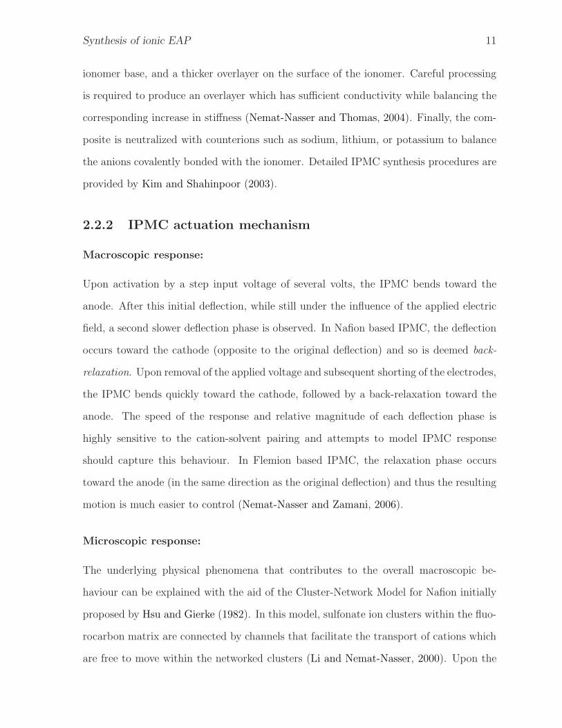
2.2.2 IPMC actuation mechanism
Macroscopic response:
Upon activation by a step input voltage of several volts, the IPMC bends toward the
anode. After this initial deflection, while still under the influence of the applied electric
field, a second slower deflection phase is observed. In Nafion based IPMC, the deflection
occurs toward the cathode (opposite to the original deflection) and so is deemed back-
relaxation. Upon removal of the applied voltage and subsequent shorting of the electrodes,
the IPMC bends quickly toward the cathode, followed by a back-relaxation toward the
anode. The speed of the response and relative magnitude of each deflection phase is
highly sensitive to the cation-solvent pairing and attempts to model IPMC response
should capture this behaviour. In Flemion based IPMC, the relaxation phase occurs
toward the anode (in the same direction as the original deflection) and thus the resulting
motion is much easier to control (Nemat-Nasser and Zamani, 2006).
Microscopic response:
The underlying physical phenomena that contributes to the overall macroscopic be-
haviour can be explained with the aid of the Cluster-Network Model for Nafion initially
proposed by Hsu and Gierke (1982). In this model, sulfonate ion clusters within the fluo-
rocarbon matrix are connected by channels that facilitate the transport of cations which
are free to move within the networked clusters (Li and Nemat-Nasser, 2000). Upon the

Synthesis of ionic EAP 12
application of an electric potential, the cations migrate through the channels toward the
cathode creating two distinct boundary layers. Clusters in the anode boundary layer are
depleted of their cations as the latter migrate toward the cathode, and as a result, the
cathode boundary layer is supplied with an excess of cations. Although the overall bal-
ance of cations within the IPMC remains unchanged, the localized imbalance of cations
in the cathode boundary layer induces bulk deformation of the IPMC as the clusters
dilate or contract according to changes in the elastic, osmotic, and electrostatic forces
present. As ion migration and solution drag is responsible for the underlying actuation,
the IPMC must be kept hydrated. This restriction poses a major design challenge for
application of IPMC actuators.
2.2.3 IPMC modelling
In a comprehensive review by Shahinpoor and Kim (2004), available models for IPMC
sensing and actuation were presented and categorized as either physical models, black
box models, or gray box models. Physical models are those in which the phenomena
which are believed to cause the electromechanical response and subsequent deformation
(in the case of actuation) or voltage output (in the case of sensing) are modeled.
Alternatively, black box models (sometimes referred to as phenomenological or empir-
ical models) have little regard for the underlying actuation mechanism and rely solely on
system identification techniques such as those presented by Mallavarapu et al. (2001) and
Bhat and Kim (2004). Finally, gray box models are a combination of the previous two,
making use of the physical laws governing the process and experimentally determined
parameters to compensate for uncaptured behaviour.
Models developed thus far vary drastically in complexity (according to their intended
use) and are typically based on one of several approaches including continuum electro-
dynamics of ionomer swelling and contraction, continuum diffusion electromechanical
models for asymmetric bending, continuum microelectromechanical models, microelec-

Synthesis of ionic EAP 13
tromechanical modelling of asymmetric deformation, time dependent phenomenological
modelling, steady state solutions based on linear irreversible thermodynamics, expanded
ion transport modelling, equivalent circuit modelling, physiochemical phenomena, and
nano-scaled physics-based modelling (Shahinpoor and Kim, 2004; Tadokoro and Konyo,
2004).
The nano-scaled physics-based model proposed by Nemat-Nasser is applicable to
many IPMC compositions as it inherently captures the effect of various solvent-cation
interactions (Nemat-Nasser, 2002). The model is also attractive because it is computa-
tionally suitable for real-time control. Once the stiffness properties have been established
for a specimen, the dynamics-related aspect of the model relies on the formulation of ex-
pressions for the displacement rate, charge distribution, and volumetric change within
the anode and cathode boundary layers. The normalized tip-displacement formula for a
specimen of length L, unit width, total thickness 2H , and bare ionomer thickness 2h is
given by
u
L=
YBL(3YIPMC − 2YB
) hLLA
4H3DA
(tC
LA
LC
− tA
), (2.1)
where u is the tip velocity, LA and LC are the effective length of the anode and cathode
boundary layers, DA is the computed diffusion rate coefficient, tA, and tC are the analyt-
ically computed cluster pressure in the anode and cathode boundary layers, and YIPMC,
YB, and YBL denote the elastic modulus of the hydrated IPMC, bare ionomer (determined
analytically), and boundary layer respectively.
Work conducted by Nemat-Nasser and Wu (2006); Wu and Nemat-Nasser (2004) con-
firms that predictions from this nano-scaled physics-based model are in good agreement
with experimental results for a wide variety of compositional IPMC variants. The model
captures both the back-relaxation phenomena, as well as the IPMC response to sudden
shorting of the electrodes. These models facilitate the design and control of IPMC as
bending actuators, and a new model for layered PPy bending actuators will be presented
in Chapter 5.

Synthesis of ionic EAP 14
2.2.4 Polyaniline fibre
Structure:
Polyaniline is unique in that it has six readily electrochemically accessible oxidation
states, three of which are relevant to this investigation (Wallace, Kane-Maguire and
Lewis, 2002; Smela et al., 2005). Emeraldine salt (ES) is the conductive form of PAni, and
hence the form of most interest to this study. Unfortunately, ES has no known solvents
unless modifications are made to the polymer such as side-group additions, see (Wei et al.,
1996). This insolubility serves as an obstacle for solution processing of the material, and
as such the PAni is often converted through deprotonation or electrochemical reduction
to the nonconductive Leucoemeraldine base (LEB) or Emeraldine base (EB) forms which
are generally soluble in solvents such as NMP. After casting or drawing into a desired
form (such as a film or fibre), the PAni can be chemically transformed back into the
conductive ES state via an oxidizing agent and/or protonic acid.
Synthesis:
The detailed polymerization reaction of PAni including the intermediate complexes is
described by Odian (2004). Most polymers are cast as fibres or films, and while the
former’s geometry lends itself well to linear actuator applications, free-standing solution
cast PAni films which may find use as a separation technology membrane tend to be too
brittle for actuation purposes (Wei et al., 1992; Xi et al., 2005). Because of this, PAni
fibre processes will be explored in favour of free-standing film production techniques.
The fibre synthesis process illustrated in Figure 2.1 has been compiled based on
procedures reported by a variety of sources and empirical laboratory experience (Liu
and Gao, 2004; Mottaghitalab et al., 2006; Mattes, Wang, Yang, Zhu, Blumenthal and
Hundley, 1997; Mattes, Wang and Yang, 1997). A 10% w/w high molecular weight
EB (300,000 MW, Sigma-Aldrich) solution in NMP is prepared. The PAni is added

Synthesis of ionic EAP 15
Synthesis
Spinning
Drawing
Doping
NMP PAni-EB / NMP PAni-LEB / NMP
Wet-spin PAni solution into fibres
Stretch fibres in water bath at temperature of 100 ◦C
Prepare solution of water, FeCl3 and CSA Immerse fibres for 45 min
Figure 2.1: Outline of PAni fibre synthesis procedure.
gradually over an hour while stirring to facilitate homogeneity. The solution is stirred
for one additional hour to ensure that the EB is fully dissolved while minimizing the risk
of gelation (Mottaghitalab et al., 2006). The mixture is then cooled to approximately
5 ◦C using an ice-water bath. To inhibit gelation in the spinning solution, the EB was
converted to LEB by means of a chemical reduction. The reduction is accomplished by
the gradual addition of a reducing agent, in this case phenyl hydrazine in the amount of
3% (of the PAni mass), which is left stirring for 3 h.
As shown in Figure 2.2, the polymer solution is transferred to a pressure vessel after
filtering through a 100 µm cell strainer. Nitrogen gas is used to drive the fluid through
an in-line 140 µm filter, and then through a spinneret. Small spinneret apertures are
used to obtain fibres with improved mechanical properties due to enhanced alignment of
the polymer chains. The polymer solution is wet-spun into a 15% NMP coagulation bath
at 5 ◦C. The presence of NMP acts as plasticizer, which enables the fibre to be drawn
since the rigid molecular chains and strong intermolecular hydrogen bonds of PAni make
it normally difficult to draw (Liu and Gao, 2004).
The fibres are then placed in a water bath at 100 ◦C to reduce the residual solvent
and subsequently stretched. The fibres may be immersed in a doping bath consisting of
1 M CSA as the dopant acid, and 1 M FeCl3 as the oxidizing agent to accomplish the
oxidative p-doping conversion to the conductive ES form.

Synthesis of ionic EAP 16
Figure 2.2: Custom-designed PAni fibre wet-spinning apparatus.
2.3 Experimental results
2.3.1 PAni-coated IPMC
To address the dehydration issues associated with operating an IPMC actuator outside of
an aqueous environment, a novel PAni-coated Nafion-Pt IPMC was produced as shown
in Figure 2.3. A Nafion-Pt IPMC synthesized according to the method described by
Shahinpoor (2005) was dip-coated in a 3% w/w PAni-EB (MW = 20,000, Sigma-Aldrich)
NMP solution to produce a conductive polymer surface coating approximately 5 µm
thick (measured from SEM). The sample was then dried under vacuum, and immersed
in a 1 M HCl solution for 24 h to dope the PAni. Surface conductivity measurements
performed using a two-probe multimeter indicated that the doping process resulted in
a surface conductivity of approximately 9.0 S · cm−1. The sample was hydrated using

Synthesis of ionic EAP 17
(a) (b)
Figure 2.3: (a) IPMC consisting of a Nafion base polymer membrane, Pt metal subsurfacelayer, and Pt metal overlayer and (b) PAni surface coating on IPMC surface.
Figure 2.4: Tip excursion of PAni-coated Nafion-Pt IPMC after 5 cycles under 7 Vapplied potential (elapsed time approximately 10 s, 27.5 mm× 2.5 mm strip)
de-ionized water, and a potential was applied to actuate the material until the maximum
displacement was achieved. The voltage was then removed, and the sample was allowed
to relax. These cycles were repeated until angular displacement reached a maximum
as illustrated in Figure 2.4. It was observed that although the PAni coating slightly
impedes the actuation response of the IPMC, dehydration effects were not prevalent. In
this manner, the PAni coating of IPMC actuators is a promising technique to extend the
operational lifetime of IPMC actuators when not immersed in an aqueous environment.

Synthesis of ionic EAP 18
Table 2.1: Experimental parameters used for spinning of PAni fibres.
Trial PAni MW Ps ds Observations[% w/w] [psi] [mm]
Dry-wet spinning:1 15 20,000 100 1 Brittle, discontinuous lumps of PAni2 25 20,000 100 1 No fibres produced (droplet formation)3 25 20,000 200 1 Thick brittle fibres (d ≈ 3 mm)4 9 300,000 1000 0.15 Discontinuous, relatively thick fibres5 9 300,000 2000 0.15 Relatively thick fibres (d ≈ 1 mm)
Wet spinning:6 9 300,000 2500 0.15 Relatively thin fibres (d ≈ 0.30 mm)7 9 300,000 2100 0.15 Relatively thin fibres (d ≈ 0.30 mm)8 10 300,000 100–500 0.15 Flexible and thin fibres (d ≈ 0.16 mm)
2.3.2 Polyaniline fibre
An investigation was conducted to determine the effect of varying spinning parameters on
fibre properties. The parameters used in the experimental trials are provided in Table 2.1,
where Ps denotes the applied pressure, ds is the spinneret diameter, and d is the fibre
diameter.
Dry-wet spinning of polyaniline:
The initial trial (1) resulted in the formation of brittle lumps of PAni with very poor
mechanical properties. The second trial (2) involved an increase in PAni concentration.
Spinning was not successful due to the increased viscosity of the solution. Trial 3 in-
volved an increase in pressure to compensate for the increased viscosity. This led to the
formation of thick and brittle fibres. Trial 4 involved significant changes: a smaller spin-
neret diameter was used for reasons previously mentioned. Also, high molecular weight
polyaniline was utilized because the longer chains improve mechanical properties and
conductivity. With this addition, the processing became much more difficult as the so-
lution would rapidly gel. The result was the formation of discontinuous, relatively thick
fibres. This was due to the blockages created at the surface of the coagulation bath.

Synthesis of ionic EAP 19
Figure 2.5: Compliant 150 µm diameter fibre produced by wet-spinning process.
Trial 5 was identical to trial 4 except with a substantial increase in pressure. The result
was continuous, relatively thick fibres exhibiting considerable die swell.
Wet spinning of polyaniline:
In an attempt to minimize die swell and surface blockages, the air gap between the
spinneret and the coagulation bath was removed, and the resulting fibres (trials 6 and
7) were relatively thin and continuous. Trial 8 was performed at a very low spinning
pressure. The fibres were subsequently drawn 20%, as this induces an increase in fibre
strength, crystallinity and conductivity. This resulted in extremely thin and flexible
fibres as shown in Figure 2.5. Flexural stresses imposed on the fibre resulted in a series
of surface microcrack formations in the tensile regions.
These results indicate that the optimal configuration of those evaluated is the wet-
spinning of 10% w/w high molecular weight PAni through a 0.15 mm diameter spinneret
at a reduced pressure of 100–500 psi. Higher molecular weight PAni resulted in more
continuous and flexible fibres that could be drawn. A small spinneret opening produced
thin and ductile fibres due to enhanced alignment of the polymer chains. Lower applied

Synthesis of ionic EAP 20
pressures resulted in a desirable state of reduced die swell. Further reduction of the die
swell phenomenon was achieved by the removal of the air gap between the spinneret
and the coagulation bath (conversion from dry-wet spinning to wet spinning). These
findings demonstrate how material composition, synthesis procedure, and processing can
be varied to yield novel EAP materials. These concepts will be employed to prepare new
EAP materials in Chapter 3 and an improved EAP material in Chapter 4.
2.4 Electrical conductivity and actuation mechanisms
ICP exhibit two behaviours of special interest for the remaining chapters of this thesis.
The first behaviour is the characteristic ability of the ICP to exhibit a degree of electrical
conductivity. This behaviour will the exploited in Chapter 3, Porous composite blends
of conductive polymers to prepare a novel low-density conductive polymer composite.
The second behaviour of interest is the electroactive actuation mechanism exhibited by
certain ICP in electrolytic environments. In Chapter 4, Fabrication and characterization
of polypyrrole trilayer actuators this actuation behaviour is harnessed to investigate lay-
ered conductive polymer bending actuators, while Chapter 5, Modelling the polypyrrole
trilayer actuation mechanism explores the coupled charge transport and solid mechanics
aspects of the actuation mechanism, and Chapter 6, Application of electroactive poly-
mers in optical systems demonstrates the application of the actuation mechanism in the
context of an experimental optical system.
2.4.1 Electrical conductivity in conjugated polymers
The common defining feature of ICP is their conjugated backbone (alternating single and
double bonds) which permits a degree of electronic conduction due to charge delocaliza-
tion. In their base form, ICP are semiconductors that exhibit poor conductivity due
to a band gap between the valence and conduction bands (typically of several electron-
Synthesis of ionic EAP 21
volts). Conductivity may be increased by up to 13 orders of magnitude by a generally
reversible process known as doping, in which the chemical or electrical addition or re-
moval of charge from the polymer backbone results in structural changes that generate
intermediate states within the band gap (Madden, 2007). Unlike conventional conduc-
tors, charge carriers in ICP are not simply holes and electrons; they are entities known
as polarons which are associated with conformational distortions along the chain Blythe
and Bloor (refer to 2005, for an in-depth treatment of the underlying theory of the ICP
electronic properties).
Several studies report significantly high conductivities in PAni derivatives such as
PAni-camphor sulphonic acid (CSA) cast from m-cresol (Joo et al., 1994). These high
conductivities, combined with their ease of synthesis and environmental stability (Lee
et al., 1995), suggest that the scope of this study pertaining to the inherent conductivity of
ICP focus on PAni in particular. PAni has the additional benefit of being a biocompatible
material (Kamalesh et al., 2000; Wang et al., 1999), which is an essential prerequisite for
many biomedical applications.
The major drawback of PAni in the conductive ES form is its intractability due to
strong intermolecular hydrogen bonding (Mattes, Wang, Yang, Zhu, Blumenthal and
Hundley, 1997). Because of this, conventional melt processing is not possible as the
polymer decomposes below a softening or melting point (Cao et al., 1992). For the
same reason, ES has no known solvents. These complications pose significant difficulties
with respect to the use of conventional polymer processing methods. These processing
obstacles are typically remedied by means of a chemical oxidation state conversion via
deprotonation or electrochemical reduction to the nonconductive LEB or EB forms which
are generally soluble in common solvents such as NMP. After casting or drawing into a
desired form (such as a film or fibre), the PAni can be chemically transformed back into
the conductive ES state via an oxidizing agent and/or protonic acid as indicated by their
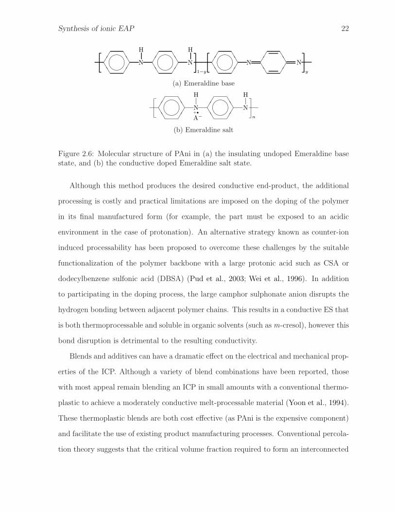
chemical structures in Figure 2.6.
Synthesis of ionic EAP 22
✔✔
❚❚
✔✔
❚❚✖✕✗✔
✔✔
❚❚
✔✔
❚❚✖✕✗✔
N
H
N
H
1−y
✔✔
❚❚
✔✔
❚❚✖✕✗✔
✔✔
❚❚
✔✔
❚❚
N
y
N
(a) Emeraldine base
✔✔
❚❚
✔✔
❚❚✖✕✗✔
✔✔
❚❚
✔✔
❚❚✖✕✗✔
N
H
N
H
nA−
+•
(b) Emeraldine salt
Figure 2.6: Molecular structure of PAni in (a) the insulating undoped Emeraldine basestate, and (b) the conductive doped Emeraldine salt state.
Although this method produces the desired conductive end-product, the additional
processing is costly and practical limitations are imposed on the doping of the polymer
in its final manufactured form (for example, the part must be exposed to an acidic
environment in the case of protonation). An alternative strategy known as counter-ion
induced processability has been proposed to overcome these challenges by the suitable
functionalization of the polymer backbone with a large protonic acid such as CSA or
dodecylbenzene sulfonic acid (DBSA) (Pud et al., 2003; Wei et al., 1996). In addition
to participating in the doping process, the large camphor sulphonate anion disrupts the
hydrogen bonding between adjacent polymer chains. This results in a conductive ES that
is both thermoprocessable and soluble in organic solvents (such asm-cresol), however this
bond disruption is detrimental to the resulting conductivity.
Blends and additives can have a dramatic effect on the electrical and mechanical prop-
erties of the ICP. Although a variety of blend combinations have been reported, those
with most appeal remain blending an ICP in small amounts with a conventional thermo-
plastic to achieve a moderately conductive melt-processable material (Yoon et al., 1994).
These thermoplastic blends are both cost effective (as PAni is the expensive component)
and facilitate the use of existing product manufacturing processes. Conventional percola-
tion theory suggests that the critical volume fraction required to form an interconnected

Synthesis of ionic EAP 23
three-dimensional network of randomly distributed spherical conductive particles in an
insulating matrix is φc ≈ 16% (Blythe and Bloor, 2005). In the case of sulphonated
PAni-PMMA solution cast films, a percolation threshold much lower than the theoreti-
cal is reported (φc ≈ 1%) (Reghu et al., 1993). This reduced threshold is attributed to
the formation of an interconnected conductive network of PAni-CSA (Yang et al., 1993).
Percolation thresholds obtained for compression molded and especially injection molded
samples are suggested to be significantly higher than their solution cast counterparts due
to: (i) flow-induced fibril alignment which disrupts the network formation resulting in
anisotropy, and (ii) elevated temperatures that result in deprotonation (Morgan et al.,
2001). From these factors, it is apparent that the thermal and rheological behaviour of
the blends have a significant effect on the resulting crystallinity, which in turn is related
to the formation of a well-connected fibrous PAni network. These processing issues and
the application of a thermal counter-ion induced processability method will be explored
in Chapter 3, Porous composite blends of conductive polymers using a DBSA counterion.
2.4.2 Actuation mechanism in PPy
The mechanism responsible for the actuation behaviour of conductive polymers is com-
plex and is a result of several interrelated phenomena. Wallace, Kane-Maguire, Spinks
and Teasdale (2002) report that the application of relatively low electrical stimulation
(on the order of a few volts) induces a change of state between an oxidized and re-
duced form of PPy. This change in the polymer structure results in volumetric swelling
(dilation) typically around 2–3% that is primarily attributed to ion migration between
the polymer backbone and neighbouring electrolyte. Secondary sources of dimensional
change include the conformational transformation of the polymer backbone (reconfigured
bond length and bond angle) and solvent drag associated with ion transport. These un-
derlying phenomena result in a macroscopic actuation which can be utilized to perform
mechanical work. One remarkable example is the use of bis(trifluoromethane)sulfon-

Synthesis of ionic EAP 24
imide (TFSI−) doped PPy films exhibiting single cycle strains in excess of 29% at rates
exceeding 10% · s−1, capable of generating blocking stresses of 22 MPa (Hara et al., 2004b;
Hara, Zama, Takashima and Kaneto, 2005). PPy actuators based on this dopant system
warrant further study as they exhibit an attractive balance of simultaneous strain and
stress capacity (7% strain at 5 MPa load).
On a molecular level, the swelling phenomenon is attributed to the transport of poten-
tially solvated ions from the electrolyte into the conducting polymer matrix to maintain
charge neutrality upon modification of the latter’s oxidation state (Fang et al., 2008), as
illustrated in Figure 2.7(a) and (b). The nature of the swelling is dependent on the relative
mobilities of the cationic and anionic species involved (and their solvent interactions), for
which the following possible concurrent reactions have been identified (Hutchison et al.,
2000):
• Reduction mechanisms based on anion egress or cation ingress:
PPy+A− + e− −→ PPy0 +A− (2.2)
PPy+A− + C+ + e− −→ PPy0A−C+ (2.3)
• Oxidation mechanisms based on anion ingress or cation egress:
PPy0 +A−−→ PPy+A− + e− (2.4)
PPy0A−C+−→ PPy+A− + C+ + e− (2.5)
• Salt draining with the gradual egress of both ionic species:
PPy0A−C+−→ PPy0 +A− + C+ (2.6)
In the system studied in Chapter 4, Fabrication and characterization of polypyrrole

Synthesis of ionic EAP 25
– +
Electrolyte
ICP
CE i
– +
e−
(a) Neutral state (b) Swollen state
C+
C+
C+
A−
A−
A−
P+
P+
P+
A−
A−
A−
P0
P0
P0
e−
C+
C+
C+
A−
A−
A−
P+
P+
P+
A−
A−
A−
P0
P0
P+
(c) As-polymerized (d) Induced oxidation
Figure 2.7: The actuation mechanism of conducting polymers results from ionic chargetransport in response to an induced change in polymer oxidation state. Here, A− andC+ denote the anionic and cationic species respectively, P0 and P+ denote the ICP inthe standard (reduced) and oxidized state respectively, and e− denotes an electron.

Synthesis of ionic EAP 26
✧✧❜❜ N
H
❜❜✧✧
)
n
(
m
+
TFSI− ⇋−e−
+e−
✧✧❜❜ N
H
❜❜✧✧
)
n
(
m
+ TFSI−
Figure 2.8: Bis(trifluoromethane)sulfonimide anions enter PPy in the oxidized state andare expelled upon electrochemical reduction of the polymer.
trilayer actuators, the overall actuation response is dominated by the movement of the
anionic species as illustrated in Figure 2.7(c) and (d). This behaviour is characterized
by reactions 2.2 and 2.4. In this specific system consisting of LiTFSI in PC, the swelling
is attributed to the transport of the non-coordinating TFSI− anion (where n and m de-
note the degree of oxidation and molecular weight respectively) (Wallace, Kane-Maguire,
Spinks and Teasdale, 2002), as indicated in Figure 2.8. The actuation mechanism can
typically generate stresses on the order of 5 MPa (Madden et al., 2004). Although strains
approaching 30% have been reported for delicate ICP of gel-like consistency (Hara, Zama,
Tanaka, Takashima and Kaneto, 2005a,b; Hara, Zama, Takashima and Kaneto, 2005;
Hara et al., 2004a,b, 2006), typical linear strains remain at only a few percent (Smela,
2003). This limitation restricts the range of suitable applications of the ICP actuator in
a linear configuration, and therefore bending actuator configurations will be targeted.
2.5 Chapter summary
This study examined the complex relationship between the microscopic material proper-
ties and the macroscopic dynamic response of IPMC and PAni actuators. Details of the
underlying microstructure were presented for each material including compositional ef-
fects and fundamental modelling approaches. Preliminary experimental synthesis results
were presented conveying a novel PAni-coated IPMC which is less prone to dehydration
than the uncoated equivalent. Parameters were investigated to facilitate the fabrica-
tion of PAni fibres by means of a wet-spinning process. These findings indicate that

Synthesis of ionic EAP 27
novel EAP materials can be fabricated by varying material composition and synthesis
procedure. The mechanism of electrical conduction in the conjugated polymer PAni is
introduced with emphasis on the related processing challenges. Finally, the electroactive
actuation mechanisms for PPy are described. Exploration of the conduction and actua-
tion phenomena in the following chapters provides the foundation for each of the main
contributions of this thesis.
List of references
Bhat, N. and Kim, W. J. (2004), ‘Precision force and position control of an ionic polymer
metal composite’, Proc. Institution of Mechanical Engineers. Part I: Journal of Systems
and Control Engineering 218(6), 421–432.
Blythe, T. and Bloor, D. (2005), Electrical properties of polymers, 2nd edn, Cambridge
University Press, Cambridge.
Cao, Y., Smith, P. and Heeger, A. J. (1992), ‘Counter-ion induced processibility of con-
ducting polyaniline and of conducting polyblends of polyaniline in bulk polymers’,
Synth. Met. 48(1), 91–97.
Fang, Y., Pence, T. J. and Tan, X. (2008), ‘Nonlinear elastic modeling of differential ex-
pansion in trilayer conjugated polymer actuators’, Smart Mater. Struct. 17(6), 065020.
Hara, S., Zama, T., Takashima, W. and Kaneto, K. (2004a), ‘Gel-like polypyrrole based
artificial muscles with extremely large strain’, Polymer Journal 36(11), 933–936.
Hara, S., Zama, T., Takashima, W. and Kaneto, K. (2004b), ‘TFSI-doped polypyrrole
actuator with 26% strain’, J. Mater. Chem. 14(10), 1516–1517.
Hara, S., Zama, T., Takashima, W. and Kaneto, K. (2005), ‘Free-standing polypyrrole
actuators with response rate of 10.8% s−1’, Synth. Met. 149(2-3), 199–201.

Synthesis of ionic EAP 28
Hara, S., Zama, T., Takashima, W. and Kaneto, K. (2006), ‘Tris(trifluoromethylsul-
fonyl)methide-doped polypyrrole as a conducting polymer actuator with large electro-
chemical strain’, Synth. Met. 156(2-4), 351–355.
Hara, S., Zama, T., Tanaka, N., Takashima, W. and Kaneto, K. (2005a), ‘Artificial fibular
muscles with 20% strain based on polypyrrole-metal coil composites’, Chemistry Letters
34(6), 784–785.
Hara, S., Zama, T., Tanaka, N., Takashima, W. and Kaneto, K. (2005b), ‘Fast stretching
artificial muscle fibres based on polypyrrole’, Polymer Preprints, Japan 54(1), 1721.
Hsu, W. Y. and Gierke, T. D. (1982), ‘Ion transport and clustering in nafion perfluori-
nated membranes’, J. Membr. Sci. 13(3), 307–326.
Hutchison, A. S., Lewis, T. W., Moulton, S. E., Spinks, G. M. and Wallace, G. G.
(2000), ‘Development of polypyrrole-based electromechanical actuators’, Synth. Met.
113(1), 121–127.
Joo, J., Oblakowski, Z., Du, G., Pouget, J. P., Oh, E. J., Wiesinger, J. M., Min, Y.,
MacDiarmid, A. G. and Epstein, A. J. (1994), ‘Microwave dielectric response of meso-
scopic metallic regions and the intrinsic metallic state of polyaniline’, Phys. Rev. B:
Condens. Matter 49(4), 2977–2980.
Kamalesh, S., Tan, P., Wang, J., Lee, T., Kang, E. T. and Wang, C. H. (2000), ‘Biocom-
patibility of electroactive polymers in tissues’, J. Biomed. Mater. Res. 52(3), 467–478.
Kim, K. J. and Shahinpoor, M. (2003), ‘Ionic polymer-metal composites: II. manufac-
turing techniques’, Smart Mater. Struct. 12(1), 65–79.
Lee, J. Y., Kim, D. Y. and Kim, C. Y. (1995), ‘Synthesis of soluble polypyrrole of the
doped state in organic solvents’, Synth. Met. 74(2), 103–106.

Synthesis of ionic EAP 29
Li, J. Y. and Nemat-Nasser, S. (2000), ‘Electromechanical response of ionic polymer-
metal composites’, J. Appl. Phys. 87(7), 3321–3331.
Liu, W. and Gao, G. (2004), ‘Preparation of conductive polyaniline fibers by a continuous
forming-drawn processing routine’, J. Appl. Polym. Sci. 93(2), 956–960.
Madden, J. D. (2007), Polypyrrole actuators: Properties and initial applications, in K. J.
Kim and S. Tadokoro, eds, ‘Electroactive Polymers for Robotic Applications: Artificial
Muscles and Sensors’, Springer, London, pp. 121–152.
Madden, J., Vandesteeg, N., Anquetil, P., Madden, P., Takshi, A., Pytel, R., Lafontaine,
S., Wieringa, P. and Hunter, I. (2004), ‘Artificial muscle technology: Physical principles
and naval prospects’, IEEE J. Oceanic Eng. 29(3), 706–728.
Mallavarapu, K., Newbury, K. and Leo, D. J. (2001), ‘Feedback control of the bend-
ing response of ionic polymer-metal composite actuators’, SPIE Smart Structures and
Materials 2001: Electroactive Polymer Actuators and Devices (EAPAD): Electroactive
Polymer Actuators and Devices (EAPAD) 4329, 301–310.
Mattes, B. R., Wang, H.-L. and Yang, D. (1997), Electrically conductive polyaniline fibers
prepared by dry-wet spinning techniques, in ‘Annual Technical Conference - ANTEC,
Conference Proceedings’, Vol. 2, pp. 1463–1467.
Mattes, B. R., Wang, H. L., Yang, D., Zhu, Y. T., Blumenthal, W. R. and Hundley, M. F.
(1997), ‘Formation of conductive polyaniline fibers derived from highly concentrated
emeraldine base solutions’, Synth. Met. 84(1-3), 45–49.
Morgan, H., Foot, P. J. S. and Brooks, N. W. (2001), ‘The effects of composition and pro-
cessing variables on the properties of thermoplastic polyaniline blends and composites’,
J. Mater. Sci. 36(22), 5369–5377.

Synthesis of ionic EAP 30
Mottaghitalab, V., Xi, B., Spinks, G. M. and Wallace, G. G. (2006), ‘Polyaniline fibres
containing single walled carbon nanotubes: Enhanced performance artificial muscles’,
Synth. Met. 156(11-13), 796–803.
Nemat-Nasser, S. (2002), ‘Micromechanics of actuation of ionic polymer-metal compos-
ites’, Journal of Applied Physics 92(5), 2899–2915.
Nemat-Nasser, S. and Thomas, C. W. (2004), Electroactive Polymer (EAP) Actuators
As Artificial Muscles: Reality, Potential, and Challenges, 2nd edn, SPIE Publications,
Bellingham, Washington, chapter Ionomeric Polymer-Metal Composites, pp. 171–230.
Nemat-Nasser, S. and Wu, Y. (2006), ‘Tailoring the actuation of ionic polymer-metal
composites’, Smart Mater. Struct. 15(4), 909–923.
Nemat-Nasser, S. and Zamani, S. (2006), ‘Modeling of electrochemomechanical response
of ionic polymer-metal composites with various solvents’, Journal of Applied Physics
100(6).
Odian, G. (2004), Principles of Polymerization, John Wiley & Sons, Incorporated, New
Jersey.
Pud, A., Ogurtsov, N., Korzhenko, A. and Shapoval, G. (2003), ‘Some aspects of prepa-
ration methods and properties of polyaniline blends and composites with organic poly-
mers’, Prog. Polym. Sci. 28(12), 1701–1753.
Reghu, M., Yoon, C. O., Yang, C. Y., Moses, D., Heeger, A. J. and Cao, Y. (1993),
‘Superlocalization of the electronic wave functions in conductive polymer blends at
concentrations near the percolation threshold’, Macromolecules 26(26), 7245–7249.
Shahinpoor, M. (2005), ‘Recent advances in ionic polymer conductor composite materials
as distributed nanosensors, nanoactuators and artificial muscles’, SPIE Smart Struc-

Synthesis of ionic EAP 31
tures and Materials 2005: Electroactive Polymer Actuators and Devices (EAPAD)
5759, 49–63.
Shahinpoor, M. and Kim, K. J. (2004), ‘Ionic polymer-metal composites: III. modeling
and simulation as biomimetic sensors, actuators, transducers, and artificial muscles’,
Smart Mater. Struct. 13(6), 1362–1388.
Smela, E. (2003), ‘Conjugated polymer actuators for biomedical applications’, Adv.
Mater. 15(6), 481–494.
Smela, E., Lu, W. and Mattes, B. R. (2005), ‘Polyaniline actuators: Part 1. PANI(AMPS)
in HCl’, Synth. Met. 151(1), 25–42.
Tadokoro, S. and Konyo, M. (2004), Electroactive Polymer (EAP) Actuators As Artificial
Muscles: Reality, Potential, and Challenges, 2nd edn, SPIE Publications, Bellingham,
Washington, chapter Modeling IPMC for Design of Actuation Mechanisms, pp. 385–
427.
Wallace, G., Kane-Maguire, L. A. P. and Lewis, T. W. (2002), Encyclopedia of smart
materials, J. Wiley, chapter Conductive Polymers, pp. 279–291.
Wallace, G., Kane-Maguire, L. A. P., Spinks, G. M. and Teasdale, P. R. (2002), Conduc-
tive Electroactive Polymers: Intelligent Materials Systems, CRC Press, New York.
Wang, C. H., Dong, Y. Q., Sengothi, K., Tan, K. L. and Kang, E. T. (1999), ‘In-vivo
tissue response to polyaniline’, Synth. Met. 102(1 -3 pt 2), 1313–1314.
Wei, X. L., Wang, Y. Z., Long, S. M., Bobeczko, C. and Epstein, A. J. (1996), ‘Syn-
thesis and physical properties of highly sulfonated polyaniline’, J. Am. Chem. Soc.
118(11), 2545–2555.
Wei, Y., Jang, G., Hsueh, K. F., Scherr, E. M., Macdiarmid, A. G. and Epstein, A. J.

Synthesis of ionic EAP 32
(1992), ‘Thermal transitions and mechanical properties of films of chemically prepared
polyaniline’, Polymer 33(2), 314–322.
Wu, Y. and Nemat-Nasser, S. (2004), ‘Verification of micromechanical models of actua-
tion of ionic polymer-metal composites (IPMCs)’, Proceedings of SPIE - The Interna-
tional Society for Optical Engineering 5385, 155–158.
Xi, B., Truong, V. T., Mottaghitalab, V., Whitten, P., Spinks, G. M. and Wallace, G. G.
(2005), ‘Actuation behaviour of polyaniline films and tubes prepared by phase inversion
technique’, Proceedings of SPIE - The International Society for Optical Engineering
5649, 436–444.
Yang, C. Y., Cao, Y., Smith, P. and Heeger, A. J. (1993), ‘Morphology of conductive,
solution-processed blends of polyaniline and poly(methyl methacrylate)’, Synth. Met.
53(3), 293–301.
Yoon, C. O., Reghu, M., Moses, D., Heeger, A. J. and Cao, Y. (1994), ‘Electrical trans-
port in conductive blends of polyaniline in poly(methyl methacrylate)’, Synth. Met.
63(1), 47–52.
Chapter 3Fabrication and percolation behaviour of
novel porous conductive polyblends of
polyaniline and poly(methyl methacrylate)
The conductive polymer polyaniline is blended with conventional industrial
thermoplastics in order to obtain an electrically conductive polymer blend
with adequate mechanical properties. Processing these polyblends into foams
yields a porous conductive material that exhibits immense application potential such as
dynamic separation media and low-density electrostatic discharge protection. In the cur-
rent study, the morphology of a thermally-processable blend consisting of an electrically
conductive PAni-DBSA complex and poly(methyl methacrylate) is explored using a two-
phase batch foaming setup. The effect of blend composition and processing parameters
on the resulting porous morphology is investigated. The impact of the underlying mi-
crostructure and blend composition on the frequency dependent electrical conductivity
is elucidated using multiple linear regression and a model is proposed. Finally, dielectric
analysis is utilized to identify the critical dispersion frequency of an unfoamed blend
composition near the percolation threshold.
33

Blends of PAni and PMMA 34
3.1 Introduction
Polymeric foams are porous materials whose inherent low-densities are ideally suited
for a wide variety of applications ranging from impact dissipating automotive parts, to
mass-critical aerospace components, and acoustic and thermal insulation (Eaves, 2004;
Klempner et al., 2004). Porous structures are categorized according to their morpholo-
gies, and one category of particular interest due to an attractive balance of mechanical
properties is known as the microcellular foams (Fu and Naguib, 2006). These foams
have average pore diameters on the order of 10 µm and pore densities on the order of
109 − 1015 pores · cm−3 (Kumar et al., 1994).
Recent studies in the field of conducting polymers have identified a variety of scenarios
for which porous conducting polymers would be advantageous to achieve improved ion
migration rates and low-density conductive blends for electrostatic discharge protection
and electromagnetic interference shielding (Zarras et al., 2003; Scrosati, 1993; Salaneck
et al., 1991; Onoda et al., 2004; Otero and Sansinena, 1995).
This study serves to bridge the polymeric foam and conductive polymer technolo-
gies by means of the thermal doping of conductive polyaniline (PAni) with DBSA in
conventional thermoplastic parent phase to produce a novel porous conductive material
with low-density properties realized through a two phase batch foaming process. It is
well-established that microcellular morphologies are readily obtained by the batch foam
processing of poly(methyl methacrylate) (PMMA) (Naguib et al., 2005; Nadella et al.,
2005; Fu et al., 2005), and that blends of PMMA and PAni-DBSA are miscible (Morgan
et al., 2001); thus PMMA has been selected as the parent phase of the polymer blends
prepared in this study.
Unlike several previous studies of nonporous solution-processed polyblends of PAni-
PMMA (da Silva et al., 2007; Yoon et al., 1994; Yang et al., 1993), the PAni constituent
will be mechanically dispersed and thermally fused within the parent phase. The effects
of blend composition, processing, and system parameters on the physical properties of

Blends of PAni and PMMA 35
the resulting porous structure are investigated with an emphasis on fabricating a wide
range of blend compositions in order to identify the effective percolation threshold range.
Finally, the impact of the microstructure on the frequency dependent electrical conduc-
tivity is elucidated.
3.2 Batch foaming process
The batch foaming process exploits the pressure dependent solubility of gasses in polymer
systems. Four major phenomena govern the batch foaming process: formation of a
gas-polymer solution, pore nucleation, pore growth, and morphology stabilization (Park
and Suh, 1996). As illustrated in Figure 3.1(a), the multiphase solution is obtained by
subjecting the specimen to an inert atmosphere at elevated pressure for a certain duration
such that the solubility limit is reached (Martini et al., 1982; Xing and Park, 2004).
For a given gas-polymer system, the saturation time is proportional to the square of
the specimen thickness according to
tsat =πh2
16D, (3.1)
where tsat is the saturation time, h is the specimen thickness, and D is the diffusion
coefficient (Balik, 1996). Hence, a disc geometry of the specimen has been stipulated
such that the aspect ratio of the specimen results in a small height, thereby minimizing
the required saturation time. Such a configuration is also conducive to accurate dielectric
analysis.
Once saturated, pore nucleation is induced by a rapid pressure drop from opening the
exhaust valve of the chamber (Colton and Suh, 1987). The decline in pressure results
in a reduction in the solubility of the gas within the polymer phase, and gas molecules
cluster and form pore nuclei.
The temperature of the specimen is then raised to reduce the stiffness of the polymer

Blends of PAni and PMMA 36
Figure 3.1: A schematic representation of the two-phase batch foaming process.
phase, thereby further promoting the pore growth process. As indicated in Figure 3.1(b),
this increase in temperature is realized by immersing the specimen in a hot water bath.
The degree of pore growth is proportional to the duration of the immersion, which is
referred to as the foaming time, tf .
Pore stabilization is achieved by quenching the specimen in cold water, thereby simul-
taneously reestablishing thermodynamic stability and raising the stiffness of the polymer
phase, which in turn arrests successive pore growth.

Blends of PAni and PMMA 37
3.3 Experimental methodology
3.3.1 Blended sample preparation
The PMMA (Sigma-Aldrich, Mw ≈ 120 000) and PAni emeraldine base (Sigma-Aldrich,
Mw ≈ 300 000) powders were initially dried under a −15 in ·Hg vacuum at 60 ◦C for a
minimum of 3 d to reduce the moisture content of the powder.
To overcome the typical restrictions associated with the infusible and insoluble nature
of the conductive emeraldine salt form of PAni, a thermally processable conductive com-
plex of PAni was prepared without the requirement for auxiliary solvents using DBSA
(Sigma-Aldrich) as the dopant (Levon et al., 1995; Titelman et al., 1997). The PAni-
DBSA complex was formed by mixing the components in the optimal 1:3 mass ratio
until a paste formed. The paste was then thermally processed in a twin-screw com-
pounder (MiniLab II HAAKE Rheomex CTW5, Thermo Fisher Scientific) operating at
140 ◦C. The screw speed was maintained at 20 rpm to provide sufficient residence time
for the characteristic paste-to-solid transition to take place, however the recirculation
was not utilized to avoid the detrimental aging effects associated with prolonged expo-
sure to elevated temperatures (Zilberman et al., 1997). The resulting product was then
cryogenically ground into a fine powder to improve dispersion within the PMMA parent
phase.
Nine compositions of the PAni-PMMA mixture were prepared by compounding pre-
mixed ratios of the powders at 180 ◦C and 50 rpm. The resulting product is then de-
posited within a 1.75 mm thick die consisting of 12 through-holes approximately 20.0 mm
in diameter.
The die is then placed between the heated plates of a hydraulic press at 180 ◦C under
3.9 MPa of pressure for 3− 4 min (Fu and Naguib, 2006). The die is then removed
from the press and quenched in water to facilitate the removal of the specimens from
the die. Finally, the samples are dried at ambient conditions for a minimum of 18 h

Blends of PAni and PMMA 38
before characterization. Once completely dry, the specimens are referred to as being
in the unfoamed condition. In the present investigation, PAni-PMMA blends of φ =
0 (pure PMMA), 0.01, 0.02, 0.05, 0.10, 0.20, 0.35, 0.50, and 1.00 PAni-DBSA were
prepared, where φ denotes the mass fraction of PAni-DBSA in PMMA (note that due to
the similar density of the blend constituents, the volume fraction of the conductive filler is
approximately equal to the mass fraction). In this regard, the composition specifications
denote the ratio of PAni-DBSA to PMMA, the actual PAni content nominally being a
fraction of the total PAni-DBSA content.
3.3.2 Microcellular processing
Compressed carbon dioxide at a pressure of 810 psi (5.6 MPa) was utilized as the gas
blowing agent, and specimens were saturated for 18 h, after which they were considered
fully saturated (Manninen et al., 2005). A water bath having a temperature of 70 ◦C was
utilized to facilitate cell growth, and specimens of varying composition were characterized
in the unfoamed condition, foamed condition with tf = 5 s, and foamed condition with
tf = 15 s.
Once foamed, the specimens were quenched in cold water to arrest the cell growth, and
subsequently dried to minimize the effects of moisture content and residual CO2 on the
foamed condition characterization process. Previous work has shown that the saturation
and subsequent desaturation of the composite with CO2 does not have a significant
impact on the electrical conductivity of the material (Price and Naguib, 2008b).
3.3.3 Characterization of porous morphology
Characterization of the specimens was performed via the measurement of several physical
parameters. Physical data collection consisted of the determination of the characteris-
tic dimensions and mass of each sample using a vernier caliper and precision balance
respectively. An approximated volume and the corresponding mass measurement were

Blends of PAni and PMMA 39
then used to estimate the density of the specimen. This characterization procedure was
performed on each sample in both the unfoamed and foamed condition such that the
relative density, ρ, was determined. The relative density is indicative of the degree of
volume expansion and is given by
ρ =ρfρp
, (3.2)
where ρf and ρp denote the density of the specimen in the foamed and unfoamed (polymer)
state respectively. Relative density measurements presented herein are based on the
average of three duplicate samples.
The cellular morphologies are also characterized by the pore density, Np. The pore
density refers to the number of pore sites per unit of original unfoamed volume which is
calculated according to:
Np =(n
A
)1.5 ρpρf, (3.3)
where n is the number of pores in a given two-dimensional area, A (Kumar and Weller,
1991). Finally, the average pore diameter, d (estimated using image analysis software) is
an additional measure of the porous morphology within the foamed polymer blend.
3.3.4 Characterization of dielectric properties
To complement the characterization of the pore morphology, frequency dependent mea-
surements of electrical properties were recorded by means of a Novocontrol Alpha-L
broadband dielectric analyzer in conjunction with a parallel plate capacitor sample cell
over a frequency range of 0.1–300 000 Hz. Samples containing PMMA were sputter coated
with platinum on opposing faces to ensure uniform electrode contact. For dielectric poly-
mer systems the complex electrical permittivity, ǫ∗ = ǫ′ − iǫ′′, is modelled by the Debye
dispersion equation:
ǫ∗ = ǫ∞ +ǫs − ǫ∞1 + iωτ
, (3.4)

Blends of PAni and PMMA 40
where ǫ∞ and ǫs are the instantaneous and static dielectric constants respectively, τ is the
characteristic dielectric relaxation time, and ω is the angular frequency (Blythe and Bloor,
2005). This model suggests that a peak in the frequency dependance of ǫ′′ corresponds
to the characteristic frequency of the conduction-insulation transition. The Debye model
was been extended by Cole and Cole who proposed a parameterization of the dispersion
equation that suggests that a plot of ǫ′′ versus ǫ′ should give a semicircle. Departures
from this shape are attributed to the statistical variation of dielectric relaxation processes
encountered in amorphous polymers (Cole and Cole, 1941; Davidson and Cole, 1950).
Several effective media theories have been proposed for blend compositions near well
defined percolation thresholds; however these models do not capture the behaviour of
the blends studied in the investigation. Alternatively, Jager et al. have shown that the
simple relation:
ωc =σDC
ǫ0ǫs, (3.5)
models the critical dispersion frequency, ωc, of a wide range of conductive particle com-
posites (Jager et al., 2001). These properties give insight into the effect of composition
and porous morphology on the electrical properties of the polymer blend.
3.4 Results and discussion
3.4.1 Samples
Samples prepared from mixtures containing 0–10% of the PAni-DBSA additive are indi-
cated in Figure 3.2 at each stage of the foaming process. The pure PMMA samples are
transparent; however the transparency diminishes upon the addition of the PAni-DBSA.
The increasing sample diameter resulting from the batch foaming process is indicative of
the additional volume resulting from pore nucleation and growth.

Blends of PAni and PMMA 41
Unfoamed
Saturated
tf = 5 s
tf = 15 s
0% 1% 2% 5% 10%
Figure 3.2: Samples of increasing PAni content at each stage of the foaming process. Thesample diameter in the unfoamed condition is approximately 20.0 mm.
3.4.2 Porous morphology
SEM micrographs depicting the evolution of the porous morphology of the polyblends as
a function of composition and state in the foaming process are shown in Figure 3.3 and
Figure 3.4 for low and high fractions of the conductive component respectively (relative
to the observed conductivity percolation threshold). The corresponding characteristics
of the pore morphologies are presented in Table 3.1.
The SEM images for the pure PMMA samples (Figure 3.3(a)–(c)) indicate the foaming
behaviour of the PMMA parent phase in the absence of the PAni-DBSA additive. In the
case of tf = 5 s (Figure 3.3(b)), a significant fraction of the pores have mean diameters
below the micron scale, and thus the morphology is considered to be a nanocellular
foam. Such pore sizes are highly desirable, especially when coupled with the observed
uniform pore dispersion. When the foaming time is extended to 15 s (Figure 3.3(c)),

Blends of PAni and PMMA 42
(a) (b) (c)
(d) (e) (f)
(g) (h) (i)
Figure 3.3: SEM images depicting the effect of blend composition and foaming time on theresulting cellular morphology for small amounts of PAni. Composition varies by row frompure PMMA, to 1% PAni-DBSA and 2% PAni-DBSA respectively. Columns indicate thematerial in the unfoamed state, foamed for 5 s and foamed for 15 s respectively.

Blends of PAni and PMMA 43
(a) (b) (c)
(d) (e) (f)
(g) (h) (i)
(j) (k) (l)
Figure 3.4: SEM images depicting the effect of blend composition and foaming time onthe resulting cellular morphology for increased PAni content. Composition varies by rowfrom 10% PAni-DBSA to 20%, 35%, and 50% PAni-DBSA respectively. Columns indicatethe material in the unfoamed state, foamed for 5 s and foamed for 15 s respectively.

Blends of PAni and PMMA 44
Table 3.1: Summary of pore morphology characteristics.
% PAni tf d Np ρ[s] [µm] [106 pores · cm−3]
0 5 1.0 7.9 0.8015 5.2 5.3 0.53
1 5 2.5 7.3 0.7415 3.5 4.8 0.49
2 5 2.2 6.8 0.6915 2.6 4.7 0.47
5 5 2.7 6.0 0.6115 3.4 4.4 0.44
10 5 2.9 6.4 0.6415 2.8 4.3 0.44
20 5 78.6 5.9 0.6015 14.8 4.3 0.44
35 5 33.0 6.7 0.6815 51.2 6.3 0.64
50 5 88.6 8.5 0.8615 47.5 8.6 0.87
100 5 - - 0.9415 - - 0.90

Blends of PAni and PMMA 45
it is observed that the apparent pore diameter is much larger, which confirms the pore
growth phenomenon. In conjunction with the pore growth is a drop in pore density
that indicates extensive pore coalescence. The images also suggest that the average pore
diameter increases with increased foaming time, and also increases as the content of PAni-
DBSA increases. The former phenomenon is expected due to the longer duration of pore
growth stage in foaming process. The latter phenomenon is attributed to the PAni-DBSA
(and the unbound excess DBSA) serving as sites for heterogeneous nucleation amid the
pore nucleation stage of the foaming process.
In contrast to prior work in which blends of PMMA and PAni were prepared by dry-
blending (Price and Naguib, 2007), the conductive component of the blend was dispersed
far more uniformly in the thermally-processed samples studied herein. In addition, little
evidence of large-scale agglomeration has been detected in comparable concentrations of
PAni-DBSA in PMMA. The improved dispersion inherent to this preparation method
reduces the effective percolation threshold, and so reduces the amount of the conductive
constituent required for the same conductivity.
The relative density metric generally decreases with increased foaming time and in-
creased PAni-DBSA content, which is in agreement with the aforementioned pore nucle-
ation and growth mechanisms. The drop in relative density is more pronounced for low
concentrations of PAni-DBSA, and approaches a limit as the PAni-DBSA concentration
is increased due to complete utilization of the saturated gas in the pore formation process.
Finally, blends of equal composition exhibit comparable pore densities (accounting for
any obvious instances of pore coalescence) regardless of foaming time. This observation
reinforces the hypothesis that the PAni-DBSA particles act as heterogeneous nucleation
sites, however the lack of a clear overall trend in the Np data with respect to com-
position (particularly for low values of PAni-DBSA) suggests that the presence of the
PAni-DBSA in low concentrations may impede the nucleation of pores when compared
with the pristine parent phase.

Blends of PAni and PMMA 46
Comparisons of the sample masses throughout the batch foaming process reveals that
the mass typically varies by less than 5%. Samples consisting of pure PMMA tend to
increase in mass slightly indicating the presence of residual water. This amount was
confirmed by TGA analysis, wherein the sample mass decreased by approximately 5%
upon heating to the boiling point of water. Blends containing the PAni-DBSA complex
generally decreased in total mass over the course of the batch foaming process. Samples
that exposed more PAni-DBSA to the immersion bath experienced larger decreases in
mass. These samples included those with large surface areas via high pore densities
(i.e. low volume fractions of PAni-DBSA) or those containing high volume fractions of
PAni-DBSA (more PAni-DBSA on the exterior surfaces exposed to water). Normalizing
these losses by blend composition indicates that the mass difference is less than the
amount of excess DBSA present in the blend (unbound DBSA represents 47% w/w of
the conductive complex). Thus, the observed decrease in sample mass may be primarily
attributed to the loss of excess DBSA during the immersion process. As unbound DBSA
does not contribute to the doping mechanism of the PAni, the loss of the former is not
expected to be significantly detrimental to the electrical conductivity of the material.
The influence of the thermal doping induced processibility approach on the result-
ing porous morphology is considerable as indicated in Figure 3.5. In the conventional
dry blending technique (Figure 3.5(a)), heterogenous regions of PAni are dispersed in
poorly fused aggregates throughout the PMMA parent phase which increases the effec-
tive percolation threshold (Price and Naguib, 2008a). Conversely, blends prepared using
the thermal doping technique exhibit uniform dispersion of the constituents in a single
homogenous phase. This even distribution of the conductive phase serves reduces the
fraction of the conductive phase required for the onset of percolation behaviour (Price
et al., 2010).

Blends of PAni and PMMA 47
(a)
(b)
Figure 3.5: SEM images depict the effect of blending technique on the resulting cellularmorphology for (a) the dry blended emeraldine salt technique and (b) the thermal dopingof an emeraldine base technique. In both cases composition is 10% PAni-DBSA andfoaming time is 5 s.

Blends of PAni and PMMA 48
3.4.3 Dielectric properties
The real component of the conductivity versus frequency for the PAni-DBSA complex and
PMMA is given in Figure 3.6 (φ = 0 and φ = 1, respectively). The data suggests that the
crossover frequency (ωc) that defines the transition from the DC region to the frequency
dependent region lies beyond the available frequency range available for the PAni-DBSA
complex. Conversely, the data suggests that the PMMA exhibits frequency dependency
over the entire frequency range under consideration. The stipulated frequency range was
determined by the design limitations of the dielectric analyzer hardware. It is apparent
from these curves that samples manufactured from the PAni-DBSA complex through
the compounding and subsequent compression molding operations are indeed electrically
conductive. Conversely, the conductivity of PMMA clearly falls within the electrically
insulative domain. Ideally, since the conductivity of the two blend components varies
by several orders of magnitude, the addition of the conductive PAni-DBSA complex to
the insulative PMMA parent phase beyond the percolation threshold would economically
impart practical conductivity levels.
In addition to the aforementioned influence of blend composition, the foaming process
significantly impacts the sample conductivity. Figure 3.7 indicates the effect of the batch
foaming process on the electrical conductivity of PAni-PMMA blends below the perco-
lation threshold. The results indicate that the foaming process has a detrimental effect
on the bulk conductivity, which is expected as the foaming process introduces insulating
gas-filled pores. Multiple linear regression using least squares analysis was implemented
to assess the relationship between the blend composition and relative density on the
resulting blend conductivity. The resulting model for blend conductivity is given by
σ′m = a0 + a1ρ+ a2φ, (3.6)
with the coefficients a0 = − 3.70 × 10⁻¹⁴ S · cm−1, a1 = 1.63 × 10⁻¹³ S · cm−1, and

Blends of PAni and PMMA 49
0.2
0.350.5
00.05
0.1
1
Frequency [Hz]
σ′ m
[S·cm
−1]
Re(σm) vs. Frequency
d.c. region dispersive region
ωc = 6.3 Hz
← →
10−2 100 102 104 10610−15
10−10
10−5
100
Figure 3.6: Blend composition (in terms of volume fraction, φ, of the PAni-DBSA com-plex) is a significant factor affecting the electrical conductivity of the composite. Note thecritical dispersion frequency at 6.3 Hz for φ = 0.2 and the improvement in conductivitycharacteristic of a percolation-type system.
00.010.020.05
Relative density, ρ
σ′ m
[×10−14S·cm
−1]
Re(σm) vs. Relative density
Decreasing φ
0.4 0.5 0.6 0.7 0.8 0.9 12
4
6
8
10
12
14
Figure 3.7: A reduction in relative density (in terms of volume fraction of the PAni-DBSAcomplex, φ) reduces the electrical conductivity of the composite (ω = 1 Hz). Solid linesindicate the conductivity predicted by Eq. 3.6 for various blend compositions.

Blends of PAni and PMMA 50
a2 = 1.62 × 10⁻¹³ S · cm−1. The multiple correlation coefficient associated with this
model is statistically significant (r = 0.9975), which suggests that the model accounts
for more than 99.5% of the physical variation in blend conductivity as a function of
composition (for φ < φc) and relative density (over the range of relative densities achieved
experimentally).
As shown in Figure 3.6, the blends with little or no PAni-DBSA exhibit the frequency
dependent electric conductivity curves typical of amorphous insulators (Price and Naguib,
2008a). Blends containing amounts of PAni-DBSA significantly above the percolation
threshold, φc, (φ ≥ 0.35) exhibit conductivities which are independent of the frequency
of the applied electric field (over the prescribed range of frequencies). For the blend
composition near the percolation threshold (φ = 0.2), the conductivity curve transitions
from the characteristic DC plateau to a dielectric response. A Cole-Cole plot (Figure 3.8)
indicates the deviation of the experimentally observed locus of dielectric components
from the Debye semicircle. Estimates of ǫ∞ = 3.6 and ǫs = 5.1 are obtained at the points
where ǫ′′ approaches zero. From these estimates the Jager relation (Eq. 3.5) predicts the
crossover frequency as ωc = 44 Hz, which is above the experimentally observed crossover
frequency. The Debye dispersion curve shown in Figure 3.9 indicates a peak in the
dielectric loss curve corresponding to a crossover frequency of ωc = 6.3 Hz. This frequency
is in agreement with the frequency dependent conductivity data shown in Figure 3.6, and
corresponds to a mean characteristic relaxation period of approximately 25 ms. Beyond
the critical frequency, the observed conductivity is dominated by the polymer polarization
response as opposed to impurities or charge carrier transport (Papathanassiou et al.,
2004).

Blends of PAni and PMMA 51
ǫ′
ǫ′′
Cole-Cole Plot
3.6 3.8 4 4.2 4.4 4.6 4.8 5 5.20.05
0.1
0.15
0.2
0.25
Figure 3.8: Cole-Cole plot indicating broad locus of dielectric dispersion phenomena(φ = 0.2).
← ǫ′
→ ǫ′′
Frequency [Hz]
ǫ′ ǫ′′
Debye Dispersion Curve (φ = 0.2)
10−2 100 102 104 1060.05
0.1
0.15
0.2
0.25
3.5
4
4.5
5
5.5
Figure 3.9: Debye dielectric dispersion curve (φ = 0.2).

Blends of PAni and PMMA 52
3.5 Chapter summary
The porous morphology of thermally-processable polymeric blends consisting of an elec-
trically conductive PAni-DBSA complex in a PMMA parent phase was explored. In
addition, the impact of the blend composition and underlying microstructure on the
frequency dependent electrical conductivity of the polyblends was elucidated. Finally,
dielectric measurements of a blend composition near the percolation threshold identified
the critical dispersion frequency indicative of the transition from a low-frequency conduc-
tor to high-frequency insulator. This study satisfies the proposed objective to develop
new engineering polymeric materials with novel electrical properties. This chapter ex-
ploited the unique electrical properties of ICPs, while the remaining chapters focus on
the actuation phenomenon.
List of references
Balik, C. M. (1996), ‘On the extraction of diffusion coefficients from gravimetric data for
sorption of small molecules by polymer thin films’, Macromolecules 29(8), 3025–3029.
Blythe, T. and Bloor, D. (2005), Electrical properties of polymers, 2nd edn, Cambridge
University Press, Cambridge.
Cole, K. and Cole, R. (1941), ‘Dispersion and absorption in dielectrics I. Alternating
current characteristics’, J. Chem. Phys. 9(4), 341–351.
Colton, J. S. and Suh, N. P. (1987), ‘Nucleation of microcellular foam: Theory and
practice’, Polym. Eng. Sci. 27(7), 500–503.
da Silva, J. E. P., de Torresi, S. I. C. and Torresi, R. M. (2007), ‘Polyani-
line/poly(methylmethacrylate) blends for corrosion protection: The effect of passi-
vating dopants on different metals’, Prog. Org. Coat. 58(1), 33–39.

Blends of PAni and PMMA 53
Davidson, D. and Cole, R. (1950), ‘Dielectric relaxation in glycerine’, J. Chem. Phys.
18(10), 1417.
Eaves, D., ed. (2004), Handbook of Polymer Foams, Smithers Rapra Press, Shawbury.
Fu, J., Jo, C. and Naguib, H. E. (2005), ‘Effect of processing parameters on cellular
structures and mechanical properties of PMMA microcellular foams’, Cellular Polym.
24(4), 177–195.
Fu, J. and Naguib, H. E. (2006), ‘Effect of nanoclay on the mechanical properties of
PMMA/clay nanocomposite foams’, J. Cell. Plast. 42(4), 325–342.
Jager, K.-M., McQueen, D., Tchmutin, I., Ryvkina, N. and Kluppel, M. (2001), ‘Electron
transport and ac electrical properties of carbon black polymer composites’, J. Phys.
D: Appl. Phys. 34(17), 2699–2707.
Klempner, D., Sendijarevic, V. and Aseeva, R. M., eds (2004), Polymeric Foams and
Foam Technology, 2nd edn, Hanser Gardner, Koesel.
Kumar, V., VanderWel, M., Weller, J. and Seeler, K. A. (1994), ‘Experimental charac-
terization of the tensile behavior of microcellular polycarbonate foams’, J. Eng. Mater.
T. ASME 116(4), 439–445.
Kumar, V. and Weller, J. E. (1991), Microcellular polycarbonate. Part I: Experiments
on bubble nucleation and growth, in ‘ANTEC-SPE’, Vol. 37, pp. 1401–1405.
Levon, K., Ho, K. H., Zheng, W. Y., Laakso, J., Karna, T., Taka, T. and Osterholm,
J. E. (1995), ‘Thermal doping of polyaniline with dodecylbenzene sulfonic acid without
auxiliary solvents’, Polymer 36(14), 2733–2738.
Manninen, A. R., Naguib, H. E., Nawaby, A. V. and Day, M. (2005), ‘CO2 sorp-
tion and diffusion in polymethyl methacrylate-clay nanocomposites’, Polym. Eng. Sci.
45(7), 904–914.

Blends of PAni and PMMA 54
Martini, J., Waldman, F. and Suh, N. P. (1982), Production and analysis of microcellular
thermoplastic foams, in ‘ANTEC-SPE’, Vol. 28, pp. 674–676.
Morgan, H., Foot, P. J. S. and Brooks, N. W. (2001), ‘The effects of composition and pro-
cessing variables on the properties of thermoplastic polyaniline blends and composites’,
J. Mater. Sci. 36(22), 5369–5377.
Nadella, K., Kumar, V., Li, W., Kawashima, H. and Shimbo, M. (2005), ‘Effect of
foaming temperature control on cell size and cell density of microcellular plastics’,
Cell. Polym. 24(2), 91–102.
Naguib, H. E., Jo, C. and Fu, J. (2005), ‘Constitutive modeling for mechanical behavior
of PMMA microcellular foams’, Bioelectroch. Bioener. 46(25), 11896–11903.
Onoda, M., Kato, Y., Shonaka, H. and Tada, K. (2004), ‘Artificial muscle using conduct-
ing polymers’, Electrical Engineering in Japan 149(4), 7–13.
Otero, T. F. and Sansinena, J. M. (1995), ‘Artificial muscles based on conducting poly-
mers’, Bioelectrochemistry and Bioenergetics 38(2), 411–414.
Papathanassiou, A. N., Sakellis, I., Grammatikakis, J., Vitoratos, E., Sakkopoulos, S.
and Dalas, E. (2004), ‘Low frequency a.c. conductivity of fresh and thermally aged
polypyrrole-polyaniline conductive blends’, Synth. Met. 142(1-3), 81–84.
Park, C. B. and Suh, N. P. (1996), ‘Filamentary extrusion of microcellular polymers
using a rapid decompressive element’, Polym. Eng. Sci. 36(1), 34–48.
Price, A. D., Kao, V. C., Zhang, J. X. and Naguib, H. E. (2010), ‘Fabrication and perco-
lation behaviour of novel porous conductive polyblends of polyaniline and poly(methyl
methacrylate)’, Synth. Met. 160(17-18), 1832–1837.
Blends of PAni and PMMA 55
Price, A. D. and Naguib, H. E. (2007), ‘Synthesis and characterization of porous poly-
aniline conductive polymers’, SPIE Electroactive Polymer Actuators and Devices (EA-
PAD) 2007 6524, 65240V–1–65240V–8.
Price, A. D. and Naguib, H. E. (2008a), ‘Synthesis and characterization of porous poly-
aniline conductive polymers’, Cellular Polymers 27(3), 201–212.
Price, A. and Naguib, H. (2008b), ‘Porous conductive polyblends of polyaniline in poly
(methyl methacrylate)’, SPIE Electroactive Polymer Actuators and Devices (EAPAD)
2008 6927(69271U-1–69271U-10).
Salaneck, W. R., Clark, D. T. and Samuelsen, E. J., eds (1991), Science and Applications
of Conducting Polymers, Taylor & Francis, Great Yarmouth.
Scrosati, B., ed. (1993), Applications of Electroactive Polymers, Chapman & Hall, Suffolk.
Titelman, G. I., Zilberman, M., Siegmann, A., Haba, Y. and Narkis, M. (1997), ‘Thermal
dynamic processing of polyaniline with dodecylbenzene sulfonic acid’, J. Appl. Polym.
Sci. 66(12), 2199–2208.
Xing, F. and Park, C. (2004), PVC foams, in D. Klempner, V. Sendijarevic and R. M.
Aseeva, eds, ‘Polymeric Foams and Foam Technology’, 2nd edn, Hanser-Gardner Pub-
lications, Koesel, pp. 300–345.
Yang, C. Y., Cao, Y., Smith, P. and Heeger, A. J. (1993), ‘Morphology of conductive,
solution-processed blends of polyaniline and poly(methyl methacrylate)’, Synth. Met.
53(3), 293–301.
Yoon, C. O., Reghu, M., Moses, D., Heeger, A. J. and Cao, Y. (1994), ‘Electrical trans-
port in conductive blends of polyaniline in poly(methyl methacrylate)’, Synth. Met.
63(1), 47–52.

Blends of PAni and PMMA 56
Zarras, P., Stenger-Smith, J. D. and Wei, Y., eds (2003), Electroactive Polymers for
Corrosion Control, American Chemical Society, Washington.
Zilberman, M., Titelman, G. I., Siegmann, A., Haba, Y., Narkis, M. and Alperstein,
D. (1997), ‘Conductive blends of thermally dodecylbenzene sulfonic acid-doped poly-
aniline with thermoplastic polymers’, J. Appl. Polym. Sci. 66(2), 243–253.
Chapter 4Evaluation of porous membrane core
elasticity and porous morphology for
polypyrrole trilayer actuators
Multilayer electroactive polymer actuators consisting of PPy films electro-
polymerized on a passive polymer membrane core have been harnessed as a
source of simple actuation. As an integral component of the actuator, the
membrane plays a vital role in the transport of ionic species and largely dictates the stiff-
ness of the layered configuration, yet in past studies, the specification of the membrane
has remained largely arbitrary. In this chapter, quasistatic and dynamic mechanical
analysis techniques are applied to investigate the impact of the mechanical properties
of the membrane on the actuation response of PPy-based trilayer bending actuators.
Candidate materials with distinctly varied microcellular morphologies are identified and
include polyvinylidene difluoride (PVDF), nylon, and nitrocellulose. The quasistatic
stress-strain response and the frequency dependent viscoelastic nature of the candidates
are then evaluated. On the basis of mechanical properties, these results indicate that
PVDF membranes are superior to the other candidates for application as trilayer ac-
tuator cores. A custom electropolymerization cell is designed and implemented for the
57

Trilayer actuator morphology 58
fabrication of TFSI− doped PPy actuators with PVDF and nylon cores under various
synthesis conditions. Finally, the electromechanical actuation behaviour of the actuators
is reported.
4.1 Introduction
ICP such as PPy and PAni have garnered significant research interest in recent years
as an alternative actuation technology as they exhibit many favourable advantages over
conventional mechanical actuator technologies (Smela, 2003). The range of motion of
these actuators has been amplified by fabricating layered configurations which bend upon
the application of an external electric field due to the net motion of ions (Wu et al., 2006;
McGovern et al., 2009; John et al., 2008; Fang, Pence and Tan, 2008; Kiefer et al., 2008).
Trilayer actuators (as illustrated in Figure 4.1) are typically employed when the ICP
actuator is required to operate in the absence of an electrolytic environment. In this
arrangement, encapsulation of the device is achieved through the electropolymerization
of a conductive polymer such as PPy onto opposing sides of a porous membrane core.
The core thus serves as an electrolyte reservoir.
The membrane material and its corresponding pore structure influence the transport
properties of the ionic species within the electrolyte and also heavily dictate the over-
all stiffness of the composite; however existing studies involving ICP trilayers and their
Figure 4.1: Periodic tip excursions exceed 20 mm for a PPy trilayer with an active lengthof 32 mm under an alternating electric potential of 4 V (frequency is 0.1 Hz).

Trilayer actuator morphology 59
application have not systematically investigated these contributions. Thus, the specifi-
cation of the membrane material and structure remains a subjective process. Actuation
response times reflect ion transport rates across the actuator layers. These rates are
dependent on tortuosity, open surface area, and surface interaction phenomena such as
adsorption. Although compensatory approaches (such as supplying a surplus of mobile
ions in electrolyte or resistance compensation via increased electric potential (Shoa et al.,
2008)) can be implemented to overcome rate limitations, the maximum actuator deflec-
tion is highly dependent on the mechanical properties of the membrane core (Alici and
Higgins, 2009; Alici, 2009).
In this study, quasistatic and dynamic mechanical analysis techniques are applied to
investigate the mechanical properties of three candidate membrane materials having dis-
tinct porous morphologies for optimization of the actuation displacement of polypyrrole-
based trilayer bending actuators. On the basis of mechanical properties, these results
indicate that PVDF membranes are superior to nylon and nitrocellulose for application
as trilayer actuator cores. Bis(trifluoromethane)sulfonimide salt (TFSI−) doped PPy
actuators with PVDF cores and nylon cores are then fabricated under various synthesis
conditions to investigate the impact of conductive polymer thickness and morphology on
the electromechanical actuation response.
4.2 Review of ICP actuator technology
As introduced in section 2.4.2, the mechanism responsible for the actuation behaviour of
conductive polymers is complex and is a result of several interrelated phenomena (Samatham
et al., 2007; Madden, Vandesteeg, Anquetil, Madden, Takshi, Pytel, Lafontaine, Wieringa
and Hunter, 2004; Shoa et al., 2010; Madden et al., 2001; Shoa et al., 2008; Madden,
Madden, Anquetil, Vandesteeg and Hunter, 2004; Wang et al., 2009; Smela et al., 2005).
When an electric potential is applied to the polymer, the primary source of actuation is

Trilayer actuator morphology 60
attributed to dilation of the polymer upon the incorporation of ions from the neighbour-
ing electrolyte (or conversely the polymer may contract upon expulsion of ions). On a
molecular level, the ions interact with the polymer backbone in order to maintain charge
neutrality upon modification in the polymer’s oxidation state.
The resulting macroscopic actuation strain is typically on the order of a few per-
cent (Madden, Vandesteeg, Anquetil, Madden, Takshi, Pytel, Lafontaine, Wieringa and
Hunter, 2004); however range of motion of these actuators can be amplified by fabricating
layered configurations that operate in a bending mode. Layered configurations consist-
ing of two ICP coatings deposited onto a porous core can be actuated such that one
ICP layer swells while the opposite ICP layer contracts. This induced differential strain
results in a macroscopic bending effect which may be harnessed to perform mechanical
work (Wu et al., 2006; John et al., 2008; Fang, Pence and Tan, 2008; Kiefer et al., 2008;
Alici et al., 2009, 2007; Alici and Huynh, 2007, 2006; Price and Naguib, 2009; Fang, Tan,
Shen, Xi and Alici, 2008). The modelling aspects of ICP trilayer actuators are presented
in Chapter 5, Modelling the polypyrrole trilayer actuation mechanism.
4.2.1 Evolution of the conducting polymer trilayer actuator
In response to the strain limitations of linear configuration ICP actuators described
in section 2.4.2, several studies have focussed on bending mode actuators that exhibit
amplified displacements. Baughman (1996) initially recognized the potential of layered
conductive polymer actuators in the mid-1990s. In general, these bending mode actuators
exist as either bilayer (unimorph) or trilayer (bimorph) configurations. In the former
configuration, the ICP is adhered to a flexible passive layer such that the swelling of the
ICP layer induces curvature in the entire composite structure. A limitation of this bilayer
approach is that the actuator must be immersed in an electrolyte solution that serves as
an ion source and sink.
From these initial developments, several subsequent advances have since emerged to

Trilayer actuator morphology 61
further refine the technology such as the inclusion of a porous substrate to improve the
mechanical properties of the actuator (Lewis et al., 1997), recognition that the electrode-
position of thin conductive polymer films results in improved actuation performance in
terms of time response and output force (Hutchison et al., 2000), and more recently the
identification of certain dopant-solvent systems such as lithium bis(trifluoromethane)sul-
fonimide salt (LiTFSI) in propylene carbonate (PC) that improve response time, force
output, or maximum tip displacement (Wu et al., 2006).
As shown in Figure 4.2, trilayer actuators consist of a passive electrolyte storage core
that is coated on adjacent faces with the conductive polymer. This semi-encapsulated
configuration permits the actuator to operate outside of an external electrolyte solution
until evaporative effects limit the ion migration capacity of the internally contained elec-
trolyte (Otero and Sansinena, 1995) (similar to the drying effect discussed for IPMC
actuators in Chapter 2). Although not yet commercially viable, such actuators have
been prototypically demonstrated as microfluidic pumps (Kiefer et al., 2008), robotic
microgrippers (Alici and Huynh, 2007), and biologically inspired synthetic fin actua-
tors (McGovern et al., 2008).
4.2.2 Polypyrrole synthesis
The electropolymerization of PPy is commonly expressed as a single oxidation reac-
tion; however four fundamental intermediate reactions must occur to obtain the desired
final product: monomer oxidation, radical-radical coupling, deprotonation and finally
chain propagation (Wallace et al., 2002). Due to the complexity of these polymerization
mechanisms, the morphology of the resulting product is highly sensitive to the synthesis
conditions. The major parameters governing the procedure largely pertain to the chem-
ical system selected such as the choice and pretreatment of monomer, dopant, solvent,
and additives (Sadki et al., 2000). In addition, electropolymerization parameters such
as the potentiostatic field strength or galvanostatic current density, the type of reference

Trilayer actuator morphology 62
Porous membrane core
Thin platinum coating
Polypyrrole outer layer(a)
(b)
Figure 4.2: The trilayer bending actuator shown in the (a) undeformed state and the(b) deformed state consists of a porous membrane core coated with PPy on oppositefaces. Ions are expelled by one ICP layer, and similarly incorporated into the opposinglayer via the porous electrolyte storage membrane.
electrode employed (if required), reaction duration and ambient temperature, and finally
membrane core selection and electroding technique are also significant. Furthermore, it
is known that the Py monomer and oxygen react to produce undesirable oligomers in a
photoaccelerated reaction (Linnell and Umar, 1955). Thus to ensure repeatability, the
as-received Py must be freshly distilled and preserved in an inert atmosphere devoid of
incident radiation.
A survey of ICP actuator synthesis techniques suggests that the most favourable
electrochemomechanical response is obtained from an electrolyte solution consisting of
PC with LiTFSI supplying the dopant ion, the distilled Py monomer, and a small amount
of water (Alici et al., 2009; Hara et al., 2004). PC exhibits a low vapour pressure which
permits the actuator to be utilized in air for an extended duration prior to succumbing to
the detrimental evaporative effects previously mentioned. LiTFSI provides counterions
exhibiting a favourable balance of large actuation strain and fast response time. The
presence of water in the polymerization solution is known to improve the quality of
the polymerized film, while performing the electropolymerization at colder temperatures

Trilayer actuator morphology 63
generally improves the resulting conductivity of the synthesized film (Sadki et al., 2000).
Selection of the core material is an important consideration as the stiffness of the
core dominates the flexural rigidity of the composite. In addition, counterions must dif-
fuse within the electrolyte storage core before they ingress into the ICP layer (Wang
and Smela, 2009; Shoa et al., 2008). Little effort however has been devoted to the
systematic selection of the core material and the impact of the core’s cellular morphol-
ogy on the resulting actuation characteristics. Numerous ICP trilayer studies have ex-
ploited the commercial availability of protein transfer membranes manufactured from
cellulose (Deshpande et al., 2005; Mahadeva and Kim, 2010; Mahadeva et al., 2011) or
PVDF (Alici et al., 2005; Minato et al., 2007); however other porous materials have been
developed for this purpose (Price et al., 2008). These membranes are highly porous:
SEM microscopy suggests that the morphology of a typical PVDF cellular morphology
is characterized by an average cell size of approximately 0.5 µm and a cell density of
approximately 7 × 10¹¹ cells per cubic centimetre. Prior to the electropolymerization
process, the faces of the membrane must be made electrically conductive by a suitable
electroding technique such as sputter coating.
4.3 Mechanical analysis of porous core materials
Several candidate membrane materials have been nominated based on the diversity of
their properties and microstructure. The candidates are commercially available and are
all rated for a retention size of 0.45 µm to facilitate comparison. As shown in Figure 4.3
the candidate materials include: (a) nitrocellulose (Hybond ECL, RPN203D, GE Health-
care), (b) PVDF (Westran CS, #10485288, Whatman), and (c) Nylon (RPN303B, GE
Healthcare). Characterization was performed on rectangular samples 6 mm wide and
13 mm long. All core materials were tested in their dry state due to environmental limi-
tations in the testing apparatus. Therefore, the stiffness of the core in service is expected

Trilayer actuator morphology 64
(a) PVDF (b) Nylon (c) Nitrocellulose
Figure 4.3: SEM micrographs indicate the highly porous nature of several typical com-mercial membrane surfaces.
to be lower than the responses observed herein due to the softening effects of the solvent.
The stress-strain behaviour was determined using a TA Instruments Q800 dynamic
mechanical analyzer (DMA) in tensile stress-strain mode at ambient temperature. A
strain rate of 1 mm ·min−1 was prescribed to obtain the elastic response. A minimum
of 4 samples were tested of each material. Due to substantial variability in the response
(tearing occurred in some samples) attributed to the inhomogeneous surface morphology
of the membranes, only a representative sample is indicated in Figure 4.4. The nylon
membrane exhibits the highest strength and stiffness (Enylon = 190 MPa), followed by
the PVDF membrane (EPVDF = 170 MPa). Although nitrocellulose was nearly as stiff
as the PVDF, it was found to be prohibitively brittle. Hence these results eliminate
nitrocellulose as a practical core material as its brittle nature and limited failure strain
may result in a reduced cycle lifetime under the imposed cyclic flexural stresses inherent
to bending mode actuators (induced flexural strains on the order of several percent have
been achieved in service, as illustrated in the following chapter).
Determination of the viscoelastic properties of the PVDF and nylon membranes was
also performed using the TA Instruments Q800 dynamic mechanical analyzer (DMA) in
tensile mode at ambient temperature. An oscillating tensile strain of 1% was prescribed
over a frequency range of 0.1 Hz to 10 Hz under a 1 mN preload. The results indicated
in Figure 4.5 confirm the increased stiffness of the nylon membrane with respect to

Trilayer actuator morphology 65
Figure 4.4: Quasistatic stress-strain tests of the candidate membrane materials indicateextremely different mechanical properties.
the PVDF. Furthermore, the tan δ measurements indicate that the PVDF has a slightly
larger degree of damping (particularly in the low frequency range). These results indicate
that PVDF is the best candidate if tip-deflection is to be maximized (Alici et al., 2007);
however the increased tip deflection is accompanied by increased strain energy dissipation.
4.4 Actuator fabrication method
Preliminary preparations include the sputter coating of a PVDF sheet and a nylon sheet
with platinum to achieve a conductive coating approximately 10 nm thick. Py was subse-
quently distilled at 131 ◦C and preserved in a dark and inert environment. The monomer
is polymerized via a multi-step electrochemical oxidation reaction (Sadki et al., 2000;
Price and Naguib, 2009). A variety of plausible growth mechanisms have been proposed,
and in all cases, the properties of the resulting polymer are highly dependent on param-
eters such as dopant, solvent, and temperature (Sadki et al., 2000).
Several custom electropolymerization vessels were designed and fabricated to prepare

Trilayer actuator morphology 66
(a) PVDF
(b) Nylon
Figure 4.5: DMA analysis within the typical low-frequency spectrum of trilayer actu-ator operation indicates similar viscoelastic losses for PVDF and nylon candidate corematerials.
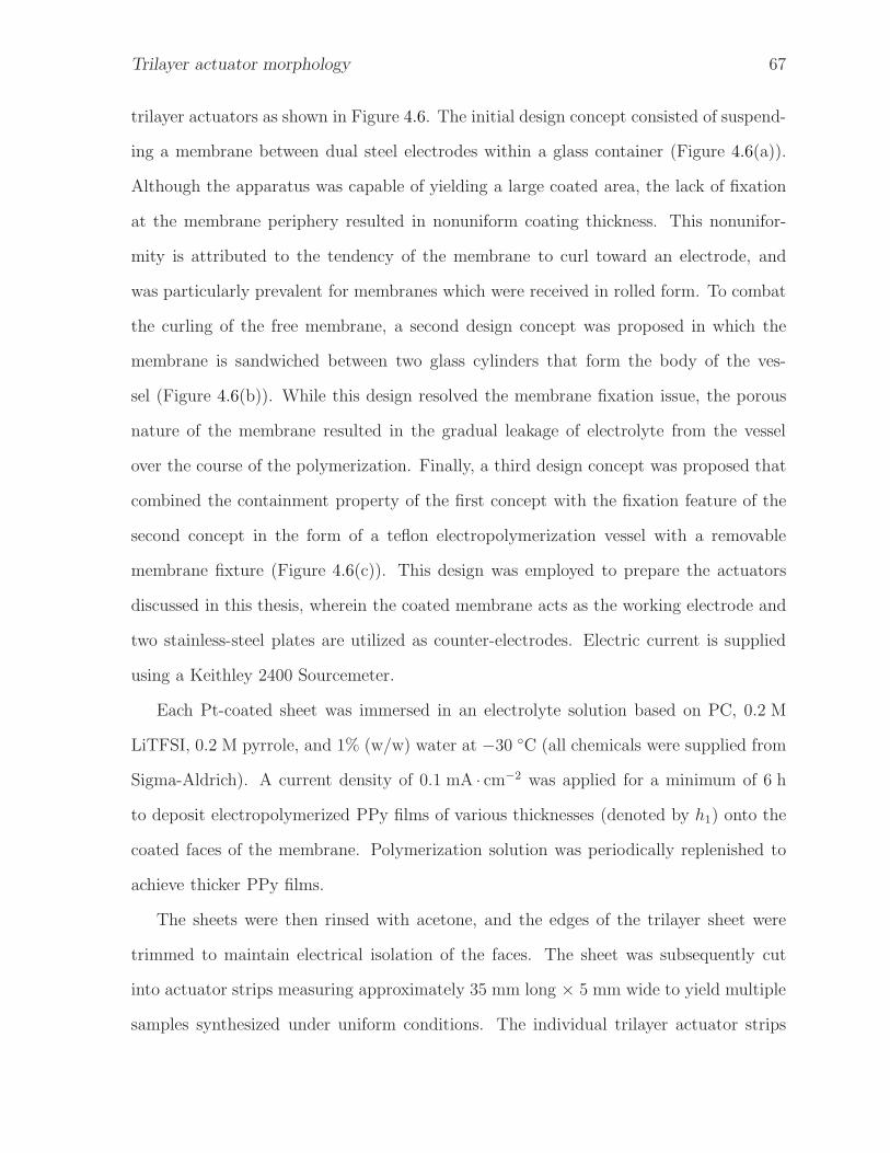
Trilayer actuator morphology 67
trilayer actuators as shown in Figure 4.6. The initial design concept consisted of suspend-
ing a membrane between dual steel electrodes within a glass container (Figure 4.6(a)).
Although the apparatus was capable of yielding a large coated area, the lack of fixation
at the membrane periphery resulted in nonuniform coating thickness. This nonunifor-
mity is attributed to the tendency of the membrane to curl toward an electrode, and
was particularly prevalent for membranes which were received in rolled form. To combat
the curling of the free membrane, a second design concept was proposed in which the
membrane is sandwiched between two glass cylinders that form the body of the ves-
sel (Figure 4.6(b)). While this design resolved the membrane fixation issue, the porous
nature of the membrane resulted in the gradual leakage of electrolyte from the vessel
over the course of the polymerization. Finally, a third design concept was proposed that
combined the containment property of the first concept with the fixation feature of the
second concept in the form of a teflon electropolymerization vessel with a removable
membrane fixture (Figure 4.6(c)). This design was employed to prepare the actuators
discussed in this thesis, wherein the coated membrane acts as the working electrode and
two stainless-steel plates are utilized as counter-electrodes. Electric current is supplied
using a Keithley 2400 Sourcemeter.
Each Pt-coated sheet was immersed in an electrolyte solution based on PC, 0.2 M
LiTFSI, 0.2 M pyrrole, and 1% (w/w) water at −30 ◦C (all chemicals were supplied from
Sigma-Aldrich). A current density of 0.1 mA · cm−2 was applied for a minimum of 6 h
to deposit electropolymerized PPy films of various thicknesses (denoted by h1) onto the
coated faces of the membrane. Polymerization solution was periodically replenished to
achieve thicker PPy films.
The sheets were then rinsed with acetone, and the edges of the trilayer sheet were
trimmed to maintain electrical isolation of the faces. The sheet was subsequently cut
into actuator strips measuring approximately 35 mm long × 5 mm wide to yield multiple
samples synthesized under uniform conditions. The individual trilayer actuator strips

Trilayer actuator morphology 68
(a) Suspended membrane (b) Sandwiched membrane
Counter electrodes
Working electrode shims
Polymerization vessel
Central membrane support
(c) Fully-fixed and contained membrane
Figure 4.6: Three generations of custom-designed electropolymerization vessels are de-picted. All designs incorporate opposing counter electrodes to simultaneously depositICP product each face of the porous membrane core.

Trilayer actuator morphology 69
(a) PVDF trilayer (b) Nylon trilayer
Figure 4.7: The trilayer cross-section consists of a platinum-coated porous membranecore with PPy coatings on the opposing faces of the core.
were then stored in a PC solution containing 0.2 M LiTFSI to maintain hydration.
4.5 Characterization of trilayer actuators
4.5.1 Analysis of trilayer microstructure
SEM images depicting the cross-sections of the synthesized actuators are shown in Fig-
ure 4.7. It is apparent from these images that the morphology of the porous core is
distinctly different for each material: the PVDF is cellular in nature, whereas the nylon
membrane is highly fibrous. Image analysis conducted with the ImageJ software indicates
that the PDVF core is approximately 63 µm thick and the sample shown is coated with
PPy layers approximately 2 µm thick. The nylon core is approximately 106 µm thick,
and it was observed that the PPy thickness is significantly nonuniform. The images also
indicate that poor adhesion may result in premature delamination of the PPy from the
nylon.
Figures 4.8 and 4.9 illustrate the nodular characteristics of the PPy layer by surface
texture and cross-section respectively. Increased reaction duration typically results in
thicker PPy deposits while nodule size typically increases with coating thickness. The

Trilayer actuator morphology 70
(a) h1 = 2.26 µm (b) h1 = 2.79 µm
(c) h1 = 4.20 µm (d) h1 = 5.87 µm
Figure 4.8: SEM micrographs indicate the nodular surface morphology of PPy films ofvarious thicknesses.
high density of small nodules observed in Figure 4.8(d) is attributed to excessive polar-
ization upon depletion of monomer in the polymerization solution, which has been shown
to affect the nodule size and film porosity (Chan et al., 2009; Pandey et al., 2003).
4.5.2 Electromechanical response
Two methods were used to assess the electromechanical response of the fabricated actu-
ators: the first consisted of measuring the maximum cyclic tip displacement and electric
current in the absence of an externally applied load, and the second consisted of mea-
suring the force generated in a fully-blocked condition. The strain-rate performance is
inherently captured in the former method, as the tip displacement was evaluated as a
function of input signal frequency to identify the bandwidth of practical operation.

Trilayer actuator morphology 71
(a) h1 = 2.26 µm (b) h1 = 2.79 µm
(c) h1 = 4.20 µm (d) h1 = 5.87 µm
Figure 4.9: SEM micrographs indicate the cross-sectional morphology of trilayer actua-tors of various PPy thicknesses.
Free tip displacement
The configuration of the displacement and force characterization apparatuses are shown
in Figure 4.10. The trilayer was suspended in a vertical configuration and driven by a
computer controlled signal generator. Relatively large displacements were captured by a
digital camera; however the small displacements inherent to low driving voltage and/or
high input signal frequency were difficult to resolve using this method, and in these
situations a laser displacement sensor (optoNCDT 1627, Micro-Epsilon) was utilized.
Figure 4.11 indicates the electromechanical response of an actuator with h1 = 2.26 µm
to a cyclic square-wave input voltage with amplitude of 0.5 V. The induced electric cur-
rents show an initial charging spike followed by a gradual reduction to a steady leakage
current. This trend is indicative of the rate at which anions are transported into the

Trilayer actuator morphology 72
(a) Displacement measurement (b) Force measurement
Figure 4.10: The (a) dual-mode displacement measurement apparatus utilizes a digitalvideo camera and a laser displacement sensor. The (b) actuator blocking force is measuredwith a 50 N load cell.
PPy through the combined effects of ionic diffusion and migration. Actuation strains
resulting from the anion transport reinforce the constitutive strain-to-charge relationship
and indicate very little time delay between the voltage step and the onset of actuator
deformation.
Laser-sensed displacement results for PVDF-based actuators of various PPy film
thicknesses are presented in Table 4.1. Data were recorded for four samples of each
film thickness; however maximum tip excursions for several samples (particularly those
with the thinnest PPy films) exceeded the range of the deflection sensor and as a result
are not reported here. The results indicate that thick PPy deposits impede the deflection
of the actuator despite the added flexural stresses they may generate. No statistically
significant differences in response time were detectable for the PPy layer thicknesses in-
vestigated (and the corresponding nodular morphologies). The variation in deflections
for the samples having h1 = 2.79 mm may be attributed to localized swelling and nonuni-
form buckling of the membrane during the electrolyte immersion phase of the fabrication
process.
Tip displacement results as a function of square-wave input signal frequency and am-
plitude are provided in Figure 4.12(a) for a PVDF-based actuator with an active length

Trilayer actuator morphology 73
Table 4.1: Maximum tip deflections as a function of electric potential (activelength: 35 mm)
h1 [µm] Sample Max. Tip Deflection [mm]No. Vapp = 1 V Vapp = 2 V Vapp = 3 V
2.79
1 16a 9 112 9 10 10.43 2 3.6 94 0.7 1.5 2
5.871 2 4.2 62 3 5.2 83 2.2 3.8 5
a Estimated from captured image.
of 32 mm and width of approximately 5 mm (using solely the digital video capture ap-
proach). The tip deflection data has been normalized by the active length of the actuator
as a means of comparison between actuators of different geometries. As expected, increas-
ing the wave amplitude accelerates the oxidation/reduction rate of the PPy, and hence
the speed of the corresponding actuation is increased. Thus, for a given charge cycle
time the actuator will displace proportionally to the input voltage. As the input signal
frequency is increased, the trilayer charge cycle time is reduced, limiting the amount of
tip displacement before polarity is reversed. The increase in displacement upon aging for
several hours in service is attributed to the gradual formation of ion channels in the PPy
layers.
As in the case for the PVDF-based actuator, the tip displacement results as a function
of square-wave input signal frequency and amplitude are provided for a nylon actuator
with an active length of 32 mm and width of approximately 6 mm (Figure 4.12(b)).
Unlike the PDVF actuator, the nylon-based actuator (which has a thicker core) exhibited
much smaller displacements relative to the PVDF-based sample. Dehydration effects were
also observed during the evaluation procedure for both sets of actuators, which imposed
a practical limit on the test duration. Actuators were observed to operate in excess of

Trilayer actuator morphology 74
Potential
[V]
Electromechanical Actuation Response
Current[A
]Position[m
m]
Time [s]
0 20 40 60 80 100 120
0 20 40 60 80 100 120
0 20 40 60 80 100 120
-10
0
10
-0.02
0
0.02
-1
0
1
Figure 4.11: The electromechanical response of an actuator to a cyclic input voltageindicates the resulting charge transport and induced actuation strains in the form ofmacroscopic tip deflection.
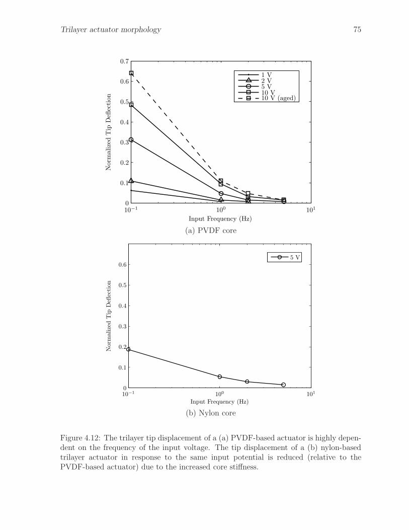
Trilayer actuator morphology 75
Input Frequency (Hz)
Norm
alize
dT
ipD
eflec
tion
1 V2 V5 V10 V10 V (aged)
10−1 100 101
0
0.1
0.2
0.3
0.4
0.5
0.6
0.7
(a) PVDF core
Input Frequency (Hz)
Norm
alize
dT
ipD
eflec
tion
5 V
10−1 100 101
0
0.1
0.2
0.3
0.4
0.5
0.6
(b) Nylon core
Figure 4.12: The trilayer tip displacement of a (a) PVDF-based actuator is highly depen-dent on the frequency of the input voltage. The tip displacement of a (b) nylon-basedtrilayer actuator in response to the same input potential is reduced (relative to thePVDF-based actuator) due to the increased core stiffness.

Trilayer actuator morphology 76
two hours at 0.1 Hz without additional encapsulation.
Blocking force capability
The trilayer blocking force was determined by actuating the device against a load cell
under various input signals. The contact surface of a 50 N load cell was equipped with a
fine edge to minimize surface tension effects between the wet actuator and the load cell.
Figure 4.13 indicates cyclic force generation of the PVDF actuator with an alternating
±5 V input voltage at a frequency of 0.1 Hz. Noise in the signal is attributed to the
resolution of the load cell employed; however curve fitting indicates that the output force
data is well modeled as a sinusoid. This is indicative of the input frequency being too
high for the actuator to arrive at an equilibrium state. These results indicate a promising
degree of repeatable control of the force output. Optimization of the force generated may
be required by adjusting the thickness of the PPy coatings on the membrane, while larger
forces may be generated by implementing a parallel array of actuators. Unlike the PVDF-
based actuator, the blocking force exerted by the nylon-based sample was not sufficiently
large enough to be resolved by the load cell. Alternative force measuring methods are
currently being explored to broaden the measurable range of force.
4.6 Chapter summary
This study first reviewed the actuation phenomena exhibited by conductive polymers
and reviewed the pertinent synthesis parameters for the fabrication of trilayer actuators.
It was then shown that mechanical properties of the membrane core are particularly vi-
tal parameters in the optimization of the response, which reinforced the importance of
a deliberate membrane selection process. The mechanical properties of several alterna-
tive core materials were subsequently characterized based on their porous morphology,
quasistatic stress strain response, and viscoelastic response. From these results, it was

Trilayer actuator morphology 77
Time (s)
BlockingForce(m
N)
0 10 20 30 40 50 60 70
-0.5
0
0.5
1
1.5
2
2.5
3
3.5
4
4.5
Figure 4.13: The force output of the PVDF actuator is highly responsive to the natureof the input signal.

Trilayer actuator morphology 78
determined that PVDF is the most favourable candidate material if tip displacement is
to be maximized. A PPy electropolymerization procedure and requisite electropolymer-
ization apparatus were then designed to synthesize ICP trilayer actuators. TFSI− doped
PPy trilayer actuators with PVDF cores and nylon cores were fabricated under various
synthesis conditions. The electromechanical actuation response of these actuators was
investigated in terms of charge transport, frequency dependent tip deflection, and block-
ing force. Larger input electric potentials induced larger bending strains as a result of
the larger counterion charge densities as expected. Tip displacements were observed to
diminish with increasing input electric potential frequency as the elapsed time between
polarity reversals is reduced, which in turn reduces the time available for charge trans-
port via ionic diffusion and migration. The blocking force generated by the actuator was
shown to be a transient phenomenon that follows the cyclic input voltage, and indicates
that these devices are particularly suitable for precision positioning applications requiring
low force. This chapter achieves the stipulated goal of investigating improved methods
for trilayer actuator fabrication.
List of references
Alici, G. (2009), ‘An effective modelling approach to estimate nonlinear bending
behaviour of cantilever type conducting polymer actuators’, Sens. Actuators, B
141(1), 284–292.
Alici, G., Devaud, V., Renaud, P. and Spinks, G. (2009), ‘Conducting polymer mi-
croactuators operating in air’, Journal of Micromechanics and Microengineering
19(2), 025017/1–025017/9.
Alici, G. and Higgins, M. (2009), ‘Normal stiffness calibration of microfabricated tri-layer
conducting polymer actuators’, Smart Mater. Struct. 18, 065013.

Trilayer actuator morphology 79
Alici, G. and Huynh, N. (2007), ‘Performance quantification of conducting polymer actu-
ators for real applications: A microgripping system’, IEEE-ASME T. Mech. 12(1), 73–
84.
Alici, G. and Huynh, N. N. (2006), ‘Predicting force output of trilayer polymer actuators’,
Sens. Actuators, A 132(2), 616–625.
Alici, G., Metz, P. and Spinks, G. M. (2005), ‘A mathematical model to describe bending
mechanics of polypyrrole (PPy) actuators’, Proc. 2005 IEEE/ASME Int. Conf. Adv.
Intell. Mechatronics pp. 1029–1034.
Alici, G., Spinks, G., Huynh, N., Sarmadi, L. and Minato, R. (2007), ‘Establishment of
a biomimetic device based on tri-layer polymer actuators – propulsion fins’, Bioinspi-
ration and Biomimetics 2(2), S18–S30.
Baughman, R. (1996), ‘Conducting polymer artificial muscles’, Synth. Met. 78(3), 339–
353.
Chan, C., Chang, S. and Naguib, H. (2009), ‘Development and characterization of poly-
pyrrole bi-layer and tri-layer thin porous films’, Smart Mater. Struct. 18(10), 104022.
Deshpande, S. D., Kim, J. and Yun, S.-R. (2005), ‘Studies on conducting polymer elec-
troactive paper actuators: effect of humidity and electrode thickness’, Smart Mater.
Struct. 14(4), 876–880.
Fang, Y., Pence, T. J. and Tan, X. (2008), ‘Nonlinear elastic modeling of differential ex-
pansion in trilayer conjugated polymer actuators’, Smart Mater. Struct. 17(6), 065020.
Fang, Y., Tan, X., Shen, Y., Xi, N. and Alici, G. (2008), ‘A scalable model for trilayer
conjugated polymer actuators and its experimental validation’, Mater. Sci. Eng., C
28(3), 421–428.
Trilayer actuator morphology 80
Hara, S., Zama, T., Takashima, W. and Kaneto, K. (2004), ‘TFSI-doped polypyrrole
actuator with 26% strain’, J. Mater. Chem. 14(10), 1516–1517.
Hutchison, A. S., Lewis, T. W., Moulton, S. E., Spinks, G. M. and Wallace, G. G.
(2000), ‘Development of polypyrrole-based electromechanical actuators’, Synth. Met.
113(1), 121–127.
John, S., Alici, G. and Cook, C. (2008), ‘Frequency response of polypyrrole trilayer
actuator displacement’, SPIE Electroactive Polymer Actuators and Devices (EAPAD)
2008 6927.
Kiefer, R., Mandviwalla, X., Archer, R., Tjahyono, S. S., Wang, H., MacDonald, B.,
Bowmaker, G. A., Kilmartin, P. A. and Travas-Sejdic, J. (2008), ‘The application of
polypyrrole trilayer actuators in microfluidics and robotics’, SPIE Electroactive Poly-
mer Actuators and Devices (EAPAD) 2008 6927.
Lewis, T. W., Moulton, S. E., Spinks, G. M. and Wallace, G. G. (1997), ‘Optimisation
of a polypyrrole based actuator’, Synth. Met. 85(1-3), 1419–1420.
Linnell, R. H. and Umar, S. (1955), ‘Aging effects in pyrrole’, Archives of Biochemistry
and Biophysics 57(1), 264–266.
Madden, J. D. W., Madden, P. G. A. and Hunter, I. W. (2001), ‘Polypyrrole actuators:
Modelling and performance’, SPIE Smart Structures and Materials 2001: Electroactive
Polymer Actuators and Devices (EAPAD) 4329, 72–83.
Madden, J., Vandesteeg, N., Anquetil, P., Madden, P., Takshi, A., Pytel, R., Lafontaine,
S., Wieringa, P. and Hunter, I. (2004), ‘Artificial muscle technology: Physical principles
and naval prospects’, IEEE J. Oceanic Eng. 29(3), 706–728.
Madden, P. G. A., Madden, J. D. W., Anquetil, P. A., Vandesteeg, N. A. and Hunter,

Trilayer actuator morphology 81
I. W. (2004), ‘The relation of conducting polymer actuator material properties to
performance’, IEEE J. Oceanic Eng. 29(3), 696–705.
Mahadeva, S. K., Yun, S. and Kim, J. (2011), ‘Flexible humidity and temperature sensor
based on cellulose-polypyrrole nanocomposite’, Sens. Actuators, A 165(2), 194–199.
Mahadeva, S. and Kim, J. (2010), ‘Nanocoating of ionic liquid and polypyrrole for durable
electro-active paper actuators working under ambient conditions’, J. Phys. D: Appl.
Phys. 43(20).
McGovern, S., Alici, G., Truong, V.-T. and Spinks, G. (2009), ‘Finding NEMO (novel
electromaterial muscle oscillator): A polypyrrole powered robotic fish with real-time
wireless speed and directional control’, Smart Mater. Struct. 18(9), 095009.
McGovern, S., Spinks, G., Xi, B., Alici, G., Truong, V. and Wallace, G. (2008), ‘Fast
bender actuators for fish-like aquatic robots’, SPIE Electroactive Polymer Actuators
and Devices (EAPAD) 2008 6927, 69271L.
Minato, R., Alici, G., McGovern, S. and Spinks, G. (2007), ‘Tri-layer conducting polymer
actuators with variable dimensions’, SPIE Electroactive Polymer Actuators and Devices
(EAPAD) 2007 6524.
Otero, T. F. and Sansinena, J. M. (1995), ‘Artificial muscles based on conducting poly-
mers’, Bioelectrochemistry and Bioenergetics 38(2), 411–414.
Pandey, S., Takashima, W., Fuchiwaki, M. and Kaneto, K. (2003), ‘Effect of film mor-
phology on the actuation behaviour in polypyrrole films’, Synth. Met. 135-136, 59–60.
Price, A. D., Liu, C. C., O’Shaughnessy, C. A. and Naguib, H. E. (2008), ‘Characteri-
zation of conductive polymer trilayer actuators for biomimetic robotics’, Proceedings
of Cansmart 2008: 11th International Workshop on Smart Materials and Structures
pp. 325–334.

Trilayer actuator morphology 82
Price, A. and Naguib, H. (2009), ‘Optimization of porous membrane core morphology
for polypyrrole trilayer actuators’, SPIE Electroactive Polymer Actuators and Devices
(EAPAD) 2009 7287, 72871P1–72871P11.
Sadki, S., Schottland, P., Brodie, N. and Sabouraud, G. (2000), ‘The mechanisms of
pyrrole electropolymerization’, Chem. Soc. Rev. 29(5), 283–293.
Samatham, R., Kim, K. J., Dogruer, D., Choi, H. R., Konyo, M., Madden, J. D., Nakabo,
Y., Nam, J. D., Su, J., Tadokoro, S., Yim, W. and Yamakita, M. (2007), Active
polymers: An overview, in K. J. Kim and S. Tadokoro, eds, ‘Electroactive polymers
for robotic applications: artificial muscles and sensors’, Springer, pp. 1–36.
Shoa, T., Madden, J. D., Fok, C.-W. E. and Mirfakhrai, T. (2008), ‘Rate limits in
conducting polymers’, Adv. Sci. Tech. 61, 26–33.
Shoa, T., Madden, J., Mirfakhrai, T., Alici, G., Spinks, G. and Wallace, G. (2010),
‘Electromechanical coupling in polypyrrole sensors and actuators’, Sens. Actuators, A
161(1–2), 127–133.
Smela, E. (2003), ‘Conjugated polymer actuators for biomedical applications’, Adv.
Mater. 15(6), 481–494.
Smela, E., Lu, W. and Mattes, B. R. (2005), ‘Polyaniline actuators: Part 1. PANI(AMPS)
in HCl’, Synth. Met. 151(1), 25–42.
Wallace, G., Kane-Maguire, L. A. P., Spinks, G. M. and Teasdale, P. R. (2002), Conduc-
tive Electroactive Polymers: Intelligent Materials Systems, CRC Press, New York.
Wang, X., Shapiro, B. and Smela, E. (2009), ‘Development of a model for charge transport
in conjugated polymers’, J. Phys. Chem. C 113(1), 382–401.
Wang, X. and Smela, E. (2009), ‘Experimental studies of ion transport in PPy(DBS)’,
J. Phys. Chem. C 113(1), 369–381.

Trilayer actuator morphology 83
Wu, Y., Alici, G., Spinks, G. and Wallace, G. (2006), ‘Fast trilayer polypyrrole bending
actuators for high speed applications’, Synth. Met. 156(16-17), 1017–1022.

Chapter 5A unified multiphysics finite element model
of polypyrrole trilayer actuators
Conducting polymer materials have demonstrated new possibilities for low
density active material actuators. This chapter reviews several existing con-
ducting polymer actuator modelling approaches, and identifies that their ap-
plicability for predictive design is limited due to their dependence on specimen-specific
properties that must be experimentally characterized a priori or monitored in situ. The
main contribution of this study is the proposal and development of a new unified mul-
tiphysics finite element model of the PPy trilayer actuation mechanism that does not
depend on any such specimen-specific parameters. The model predicts the structural de-
formation of trilayer actuators using only material properties such that the model itself is
sample independent and thus may have practical use as an electroactive polymer design
facility. Comparison with published data indicates that the model predictions fall within
95% confidence intervals throughout the entire range of input potentials evaluated.
84

Multiphysics modelling of ICP actuators 85
5.1 Introduction
Conducting polymer (CP) actuators† have demonstrated a new possibility for lightweight
active material actuators. Despite the development of several constitutive models which
capture aspects of the underlying physical phenomena, a comprehensive model that ac-
curately predicts their electro-mechanical response remains elusive. This chapter reviews
the existing conductive polymer actuator modelling approaches and indicates their re-
spective advantages and drawbacks: namely the dependence of such models on specimen-
specific properties that must be individually characterized a priori or monitored online.
The aforementioned difficulties are addressed through the proposal and development of a
new unified multiphysics finite element model that predicts the structural deformation of
trilayer actuators using only material properties. Deflection curves as a function of input
voltage produced by the proposed model are then validated against published data. This
work provides the modelling foundation for a future study to predict trilayer actuator
bandwidth.
5.2 Review of existing CP actuator modelling ap-
proaches
An understanding of the underlying conducting polymer actuation physics is a crucial
precursor to the determination of an optimized actuator configuration. This section elu-
cidates the pertinent charge transport and electrochemomechanical models to identify
the parameters that dictate the actuation response of PPy-based trilayer bending actu-
ators. These concepts are employed to forecast the charge transport phenomena within
the actuator layers using finite element analysis.
†In this chapter, the nomenclature conducting polymer has been adopted in place of inherently con-
ducting polymer or conductive polymer to reflect established conventions among the EAP modellingcommunity.

Multiphysics modelling of ICP actuators 86
The interdisciplinary nature of these actuators consisting of electrical, mechanical,
and chemical phenomena has resulted in the suggestion of analytical models with varying
foundations. Two approaches significant to the proposed model include charge transport-
based formulations such as those proposed by Wang et al. (2006); Wang and Smela (2009)
and electrochemomechanical models such as those proposed by Fang, Tan, Shen, Xi and
Alici (2008); Alici and Huynh (2006); Fang, Pence and Tan (2008). The remainder of this
section reviews existing approaches with special emphasis on the aforementioned models
that form the foundation of the new model proposed in Section 5.4.
5.2.1 Diffusive Elastic Metal model
The seminal development relating the underlying actuation mechanism to the macro-
scopic deformations exhibited in CP materials was the introduction of the Diffusive
Elastic Metal (DEM) model by Madden et al. (2001) for CP films in electrolyte. The
equivalent circuit representation of the model is illustrated in Figure 5.1, and the cor-
responding mechanical response is formulated on the concept that the induced material
strain is proportional to the ionic charge density. Thus, at equilibrium the strain, ǫ, in
the CP bulk is given by:
ǫ = α ·CV ·Vapp +σ
E(5.1)
where Vapp is the applied potential, α is the strain-to-charge ratio, CV is the volumetric
capacitance, and the applied stress and polymer stiffness are given by σ and E respec-
tively. The strain-to-charge ratio represents the electromechanical coupling of the CP
actuation phenomenon. An important facet of the model is that this factor is analogous
to a thermal expansion coefficient that responds to ionic charge as opposed to a tem-
perature gradient (Madden, 2007; Madden, Madden, Anquetil, Vandesteeg and Hunter,
2004; Shoa et al., 2008). This relation is the foundation upon which many subsequently

Multiphysics modelling of ICP actuators 87
CiC
ZDiD
R
V
i
Figure 5.1: The equivalent electrical circuit of the DEM model consists of a capacitivecharging element, a diffusive impedance element, and a resistive element. Here C is thecapacitance of the double-layer (of thickness δ), R the electrolyte resistance and ZD isthe impedance associated with ionic charge transport dominated by diffusivity D.
reported models are derived.
5.2.2 Numerical methods: thermal expansion analogues
Various finite element models have also been reported that have been implemented using
the ANSYS® software package (Alici, Metz and Spinks, 2006; Minato et al., 2007; Alici
et al., 2005). Since software routines that capture thermal expansion are well established
in the FEA software, the models exploit the analogy of the strain-to-charge ratio as an
equivalent thermal expansion coefficient to predict the static actuator deflection. Al-
though these models have been utilized in specific instances to assist in the optimization
of actuator geometry, they are subject to the heuristic determination of certain model
parameters. Furthermore, these models are not suitable for establishing the transient
behaviour of the actuator in that they do not consider ion diffusion rates.
5.2.3 Electrochemomechanical models
Having established the DEM model for bulk CP materials, the research community pro-
posed extended models for linear and multilayered bending actuators. Della Santa et al.
(1997) proposed a second order lumped parameter model for linear CP actuators that

Multiphysics modelling of ICP actuators 88
was shown to correlate well with experimental data. The model incorporates viscoelastic
effects; however it relies extensively on curve fitting to quantify estimates of the unknown
model parameters. For bilayer CP actuators, Pei and Inganas (1992) proposed a sensitive
model suitable for thick polymer layers using a bending beam formulation in conjunction
with a mathematical model of cation transport.
Electrochemomechanical (ECM) models for trilayer CP actuators are generally phe-
nomenological extensions of the DEM model in which an abstraction of the ionic response
is achieved through an equivalent electrical admittance circuit (Shoa et al., 2008; Mad-
den, Madden, Anquetil, Vandesteeg and Hunter, 2004). This abstraction is then coupled
with the principle that the polymer dilation is a function of the ionic charge transferred
to it, and thus an empirically determined strain-to-charge ratio is introduced. Figure 5.2
indicates that the functional elements of the model proposed by Fang, Tan, Shen, Xi and
Alici (2008) include an admittance module, an electromechanical coupling module, and
a mechanical output module. This model outputs the free tip displacement of a trilayer
actuator when an input potential is prescribed.
With the ultimate goal of developing trilayer based microgrippers, Alici and Huynh
(2007, 2006); Alici, Mui and Cook (2006) have proposed several variants of a bending
curve ECM model that may be utilized to predict the bending curve, blocking force and
maximum tip displacement for trilayer actuators. The model relies on the experimen-
tal determination of a voltage-dependent proportionality coefficient, α∗, which as in the
DEM model encapsulates the electromechanical coupling inherent to the underlying ac-
tuation mechanism. Characteristic values of α∗ must be obtained experimentally at each
operating voltage in the absence of a tip-constraining force by observing the actuation
curvature, κ:
α∗(V ) = −EIκ
E1bhp(hp + hm), (5.2)

Multiphysics modelling of ICP actuators 89
Fang ECM modelElectro-
mechanicalcoupling
Electricaladmittance
Solidmechanics
Hemholtzlayer
thickness
Diffusioncoefficient
Resistance
Capac-itance
CP filmthickness
CP filmdimensions
CP filmstiffness
Strain-to-chargeratio
Viscoelas-ticity
Trilayerdimensions
Input:Voltage
Electriccurrent
Inducedstress
Output:Tip
deflection
Figure 5.2: The electrochemomechanical model postulated by Fang, Tan, Shen, Xi andAlici (2008) relates the actuator tip deflection to the input electric potential in conjunc-tion with geometric, electrical and mechanical material properties.

Multiphysics modelling of ICP actuators 90
where EI is the flexural rigidity of the complete actuator, E1 is the Young’s modulus
of PPy, b is the actuator width, and finally hp and hm are the PPy and PVDF layer
thicknesses respectively. Once α∗ has been determined, the maximum blocking force, F ,
may be predicted according to:
F =E1bα
∗hp(hp + hm)
L. (5.3)
Finally, a non-linear second-order differential equation relating the actuator deflection
curve, v, to the electrical and mechanical properties of the actuator was proposed of the
form:
v′′ − (1 + (v′)2)
3α∗V C(hm + hp)
2bL[EPPy(h3
m − h3p) + EPVDFh3
p
] = 0. (5.4)
The deflection is obtained by solving this equation numerically and has shown reasonable
agreement with experimental results; however the model is not accurate for tip excursions
exceeding 90◦, and is incapable of predicting the transient actuation response.
Alici (2009) recently reported a non-linear implicit blocking force model that has been
shown to output accurate blocking force values at various static tip deflection values;
however the proposed model relies on the determination of sample specific properties
a priori (such as blocking force versus input voltage curves). Although this approach
extends our understanding of the actuation phenomena, it has limited use as a predictive
design tool.
5.2.4 Charge transport models
As the actuation mechanism ultimately depends on the motion of ionic charges, a charge
transport model capturing the diffusion and migration of charge carriers (well known in
the fields of fuel cells, polyelectrolyte gels, and ionomeric polymer-metal composites) has

Multiphysics modelling of ICP actuators 91
been applied by Wang and Smela (2009) to model a single layer of conducting polymer in
electrolyte. Such models predict charge transport via migration and diffusion processes
as described by the Nernst-Planck equation in terms of the reaction time, t, as:
∂Ck
∂t= ∇ · (Dk∇Ck + zkµkFCk∇φ) (5.5)
where k indicates the species under consideration and F is the Faraday constant. For the
anionic species k is denoted by A, for hole distribution in the CP domain, k is denoted
H, and for the mobile cationic species in electrolyte, k is C. The concentration of species
k is Ck, the species diffusion coefficient is Dk, the species valence charge number is zk,
the species ionic mobility is µk, and φ is the local electric potential. Poisson’s equation is
introduced to couple the electric potential with the local net charge density, ρ, according
to:
ε0∇ · (εr∇φ) = −ρ = −F
∑
k
zkCk (5.6)
where ε0 is the permittivity of free space and εr is the medium dielectric constant. While
the transient nature of this formulation is particularly useful for predicting actuator
response times, it does not consider any actuation phenomena. An accurate model of
charge transport additionally alleviates any requirement for online current monitoring
inherent to some ECM approaches (Fang, Tan, Shen, Xi and Alici, 2008), hence it is
proposed herein to unify the charge transport and ECM approaches within a single
comprehensive actuator model that can be utilized for predictive design.
5.3 Design considerations for trilayer actuators
This section summarizes several key relationships that define the actuation capability of
an ICP trilayer to aid engineers with the design process. Optimization methods can be

Multiphysics modelling of ICP actuators 92
applied to obtain the required design parameters given target performance requirements
in terms of desired deflection, force output and speed of response (such activities were
beyond the scope of this study).
5.3.1 Force output at equilibrium
Following the derivation by Alici, Mui and Cook (2006), an expression for the output force
can be obtained under the assumptions that the electrode layers contribute no additional
stiffness, induced stresses are uniform within the CP layers and oriented solely along
length axis of actuator (not considering generalized Hooke’s Law), the strain distribution
from the neutral plane is linear, and gravitational effects are negligible. Under these
assumptions, the output force is given by:
Fout =b
LαECPCVV hp (hp + hm) . (5.7)
Hence force output may be increased by reducing the length, increasing the layers thick-
nesses, and increasing the width. The latter result has physical limitations, as increasing
the width introduces a second bending axis that impedes the displacement capability.
5.3.2 Displacement capability
For a given length of actuator in the absence of an external load, increased displacement
is achieved by maximizing curvature according to:
κ =M
EI=
3
2
αECPCVV hp (hp + hm)
ECP
(hm
2+ hp
)3+ (Ecore −ECP)
(hm
2
)3 . (5.8)
From this expression displacement is increased as the core thickness is reduced. Further
opportunity for constrained optimization exists given typical material parameters, how-
ever these activities are beyond the scope of this work. Additional strategies for achieving

Multiphysics modelling of ICP actuators 93
large displacements at resonant frequencies have been investigated by John et al. (2008).
5.3.3 Time response
Fast responding actuators are desirable in order to achieve maximum power density.
The factors affecting actuation rate of conducting polymer actuators were investigated
by Shoa et al. (2008). These rates are shown to be highly dependant on the actuator
geometry, with transport times proportional to the square of the layer thickness. Hence
faster response times are achieved with thin CP layers. Transport times can also be
reduced (linearly) by increasing the ionic conductivity of the electrolyte.
5.3.4 Comparison with other actuation technologies
A recent survey of alternative actuator technologies compiled by Brochu and Pei (2010)
provides an update to the seminal survey reported by Madden, Vandesteeg, Anquetil,
Madden, Takshi, Pytel, Lafontaine, Wieringa and Hunter (2004). These surveys indicate
that conductive polymer actuator technology is particularly attractive to designers due
to their favourable balance of force and stroke. This combination results in unmatched
elastic energy densities of 23 J · g−1, however power density will remain relatively low
unless miniaturization techniques are employed to improve the time response. The poor
coupling efficiency of < 1% (and therefore poor mechanical efficiency) combined with
the additional need to encapsulate trilayer actuators remains a major obstacle for mass
commercialization.
5.4 A new unified multiphysics finite element model
Although each of the currently available modelling approaches provide key insights into
CP actuator performance, no single model is sufficiently comprehensive for actuator
design purposes. In particular, charge transport models do not treat the mechanical
Multiphysics modelling of ICP actuators 94
response necessary to characterize actuator performance, while the ECM models assume
uniform ion concentrations in the CP layers and additionally require that the electric
current be monitored in situ. Thus, these models are not suitable for predictive actu-
ator design. This lack of a comprehensive model has prompted the development of a
new hybrid model that incorporates aspects of each existing approach into a new uni-
fied multiphysics finite element model (UMP-FEM). The following sections describe the
implementation of the proposed model.
5.4.1 Model identification
The primary utility of the proposed model is to predict the deflection of a trilayer actuator
based solely on the actuator geometry and material properties in response to an applied
electric potential. The multiphysics model proposed herein is comprised of two distinct
yet coupled modules. The first is a one-dimensional transient charge transport model
that accounts for the redistribution of ionic charge carriers and holes within the trilayer
structure as a direct result of an applied electric potential. The second is a stationary
two-dimensional solid-mechanics model that simulates the structural deformation of a tri-
layer actuator based on the results of the 1D charge transport model (transient simulation
is also possible when non-steady ion transport and inertial effects are to be considered).
This modelling strategy permits the investigation of ion distributions and the resulting
nonuniform actuation stresses they induce. Thus, the model is particularly well-suited
for layer thickness optimization under transient operating conditions. Coupling between
the two models is realized via a stress-to-charge ratio (as in Equation 5.1) such that the
predicted curvature-potential proportionality coincides with the experimental data re-
ported by Alici, Mui and Cook (2006) throughout the reported range of applied voltages
(0.2–0.8 V). Segregation of the transport physics and solid mechanics domains drastically
reduces the problem complexity and permits an approximate simulation to be computed
without extensive computational resources. These one-way couplings neglect concen-
Multiphysics modelling of ICP actuators 95
tration gradients arising from localized deformation. The multiphysics model has been
implemented using the COMSOL Multiphysics® V4.2 software. Material properties are
currently defined as isotropic; however the model can readily be extended to incorporate
anisotropic effects related to polymer chain alignment processes such as pre-stretching,
which can enhance their electroactive response in certain directions.
5.4.2 Charge transport
Model structure
The geometry for the charge transport model consists of three collinear domains repre-
senting each of the three layers of the actuator (an extension of the single layer model
introduced in Section 5.2.4). The CP layer thickness is hp = 50 µm and the porous
membrane core thickness is hm = 110 µm in accordance with published experimental
validation data. A mesh consisting of 840 elements was generated from the geometry to
capture the large concentration gradients at the interface of adjacent domains (0.25 µm
element length). The model determines the spatial distribution and temporal evolution of
the electric potential, cation concentration, anion concentration, and hole concentration.
This one-dimensional model assumes that the potential and concentration profiles are
independent of the actuator length. This assumption is suggested on the basis that the
presence of the conductive undercoating at the membrane-CP interface minimizes these
losses. This approach is implemented using the electrostatics interface of COMSOL
Multiphysics®, and the transport of diluted species interface specific to the Chemical
Engineering Module (one transport interface per mobile species). The latter models both
diffusion and migration (electrophoretic) transport mechanisms and neglects convection
in the manner of the system described by the system of Equations 5.5 and 5.6. Boundary
conditions are specified for the electrostatics interface that consist of an electric ground
and an applied electric potential on the boundaries adjacent to external electrodes as

Multiphysics modelling of ICP actuators 96
hp hm hp
x
CP Membrane CP
− +
Vapp
JH,efflux = µHCHEcathode JH,influx = −JH,efflux
Cathode Anode
JH JHJC
JA
JH · n = 0 JH · n = 0
JC · n ≈ 0 JC · n ≈ 0
JA · n = 0 JA · n = 0
Figure 5.3: The boundary and domain conditions imposed in the proposed charge trans-port model. Although less dominant for the electrochemical system under consideration,cation flux also exists in the CP domains.
indicated in Figure 5.3.
Flux boundary conditions are also enforced to simulate the transport of holes be-
tween CP layers via the external circuit as indicated in Figure 5.3. These conditions
include the nondimensional form of Ohm’s law relating current density to the local
electric field strength as well as the implicit availability of negatively charged sites
for holes to be transported into to satisfy charge neutrality within the domains. The
saturation phenomena of anions observed experimentally has been introduced in the
model by the imposition of a smoothed step function. The function output smoothly
switches from 1 to 0 when the saturation fraction CA,electrolyte/CA,electrolyte,max approaches(CA0,electrolyte +
12Qmol
)/ (CA0,electrolyte +Qmol). The transition zone has a width of
Qmol/ (CA0,electrolyte +Qmol) ,
where Qmol denotes the molar concentration of free anionic charge carriers given by
Qmol = Q/F , and Q is the net charge. The maximum permissible concentration was

Multiphysics modelling of ICP actuators 97
stipulated as CA,electrolyte,max = 6 mol · l−1. The function limits the influx by multiplying
the species’ mobility by the function output, thereby effectively suspending concentration
increases due to migration as the maximum redox charge is approached. The same
approach was applied within the CP domain to diminish the ionic mobility of the anionic
and cationic species as the solubility limit is approached so that physically excessive
concentration gradients are minimized.
Simulation definition and model parameters
A parametric study is implemented to evaluate the transient charge transport model at
different input voltages to investigate the evolution of charge concentration profiles in
terms of both short-term response characteristics and final values after sufficiently long
time periods. The transient solver implements the MUMPS algorithm using a relative
tolerance of 0.1%. Time-stepping was implemented using the Generalized-α algorithm
with a simulation duration of 500 s.
The actuation response is generally attributed to the transport of a dominant ionic
species that not only depends on the relative size of the anion and cation, but also
the coordination number of their respective solvation shells (Skaarup et al., 2000). The
chemical system modeled in this study consists of TBA+ cations and PF−6 anions in
a highly polar PC solvent with εr = 64.92 (Wypych, 2008). In this system cations
are effectively immobile (due to their size and interaction with the solvent), and so the
actuation mechanism is dominated by anionic transport. In practice, this behaviour is
corroborated experimentally by the observation that the anode of the trilayer undergoes
a net volumetric dilation, which signifies that the response is dominated by the ingress
of anions (the converse is true at the cathode).
Reported diffusion rates for ions in PPy vary greatly due to the variety of electrolytes,
impact of polymer morphology, and measurement technique employed. A simplified
approach based on the well-known Cottrell relation suggests that an estimate of the

Multiphysics modelling of ICP actuators 98
diffusion coefficient is given by the proportionality between electric current and the square
root of elapsed time (Baum, 2007). Suarez et al. (2005) have reported on the disparity
between actual diffusion rates and those predicted by the Cottrell relation, and have
shown that the formulation does not adequately describe the transport of ions within
conducting polymers that undergo structural transformation. Thus, the actual time
response is expected to be slower than the model predicts when the diffusion coefficient
is determined using the Cottrell model. In the present study, the diffusion coefficient
D = 2 × 10⁻¹⁰ m2 · s−1 reported by Fang, Tan and Alici (2008) was utilized for the
PF−6 anions, while the diffusion rate of the cationic species was prescribed as 1% of
the anionic in the CP layers. It is unclear if the diffusivity reported by Fang, Tan and
Alici (2008) includes migrative effects; therefore a systematic investigation of diffusion
rates for various ions in CP films is suggested as prerequisite future work before accurate
characterization of transient actuator performance can be attained. The diffusion rate
of holes is taken to be the same as the anions. In the trilayer case, an effective diffusion
coefficient for the core domain that accounts for the open area and tortuosity inherent
to the porous structure is considered (Price and Naguib, 2009). The ionic diffusivities in
electrolyte were approximated as 103 times higher for the anions (with resect to the CP
diffusivity), and the cation diffusivity was specified as 10% of the anionic counterions.
As proposed by Wang et al. (2009), the model compensates for the variation of dielec-
tric constant with polymer doping level such that the relative permittivity varies between
4 in the undoped state to 1000 in the highly-conductive fully doped state. This assump-
tion permits migration effects within the conducting polymer to be captured (in contrast,
the DEM model depicted in Figure 5.1 assumes that transport within these regions is due
to diffusion only). The Einstein relation was employed for the determination of charge
carrier mobilities (see Wang et al., 2009, for detailed justification).
Finally, the volumetric capacitance CV = 31.44 MF ·m−3 is prescribed based on data
reported by Fang, Tan, Shen, Xi and Alici (2008, Figure 8) that utilizes scaling laws to

Multiphysics modelling of ICP actuators 99
characterize the double-layer capacitance. The double-layer capacitance per unit area
C0 = 7.86× 10⁻⁷ F ·mm−2 was normalized by the reported estimate of the double-layer
thickness δ = 25 nm in order to obtain the capacitance per unit volume in the polymer
bulk (after Madden, 2000). This parameter is a characteristic property of the synthesized
CP system (but is independent of specimen size), which is then used to determine the
liberated charge density assuming a purely capacitive response as in the DEM model:
Q = CV ·Vapp. (5.9)
The initial concentrations of charge carriers in each domain are then determined ac-
cording to the charge density. The model does not consider the possibility of non-zero
activation energy; hence the model will have limited accuracy when the applied poten-
tial is very small. In the electrolyte and electrolyte-saturated anode domains the initial
concentration of anions and cations is 0.25 mol · l−1 (Alici, Mui and Cook, 2006) (and no
free holes). The cathode, having been rapidly redox switched by the applied potential
at t0, contains 0.25 mol · l−1 of cations, 0.25 mol · l−1 +Q/F of free anions, and Q/F of
free holes.
Simulation results
Figures 5.4 to 5.7 illustrate the transient solution to the transport problem for an ap-
plied potential of 0.8 V. The solution exhibits qualitative behaviour comparable to that
proposed by Madden, Madden, Anquetil, Vandesteeg and Hunter (2004), and addition-
ally retains migration effects of the charge transport simulation proposed by Wang et al.
(2009).
The transient evolution of the electric potential is depicted in Figure 5.4. The initial
profile reflects the expected potential drops in accordance with the stipulated electrical
permittivity of the layers. The negative electric field drives positively charged cations and

Multiphysics modelling of ICP actuators 100
holes toward the cathode, while negatively charged anions are driven toward the anode.
Charge depletion and accumulation layers form at the interface of the CP layers and
membrane core where relative differences exist in transport rates in the adjacent domains.
As the cations under consideration are less mobile than their anionic counterparts an
asymmetry arises in their concentration profiles; this asymmetry is also reflected here in
the electric potential profile.
The concentration profile of the anionic species depicted in Figure 5.5 is of particular
interest since the relatively mobile anionic species is the primary contributor to the in-
duced mechanical stress. In the cathode CP layer the initial concentration consists of the
anions liberated by redox switching induced by the applied potential (corresponding to
the initially present holes), as well as the initial concentration of anions in the electrolyte.
As time progresses, the applied electric field drives the anions toward the anode, gradu-
ally depleting anions at the cathode CP layer-membrane interface. Hole recombination
at the cathode and the relative immobility of the cations result in a further reduction
of anions at the cathode CP layer-electrode interface such that local charge neutrality is
maintained. A large concentration peak develops at the anode CP layer-membrane inter-
face as a result of the anionic saturation phenomena captured by the model. This peak
suggests that the relatively high mobility of anions in the CP layers coupled with the
initial electrolyte concentration provides an ample supply of anions for the oxidized CP
layer. The effect becomes more pronounced as time elapses indicating that the prescribed
electrolyte concentration is sufficiently high to facilitate fast double-layer charging, and
the resulting concentration gradients maximize diffusion flux rates across the interface
(in addition to migrative effects). Note that the concentration of anions in the anode
CP layer is not uniform under transient conditions, which results in nonuniform induced
mechanical stresses. Previously reported models of CP trilayer actuators do not capture
this effect.
The hole transport depicted in Figure 5.6 indicates two characteristic behaviours in

Multiphysics modelling of ICP actuators 101
the CP layers. In the cathode CP layer a non-zero initial hole concentration arises from
the assumption of rapid liberation of holes upon application of the electric potential. As
time elapses, holes migrate toward the cathode electrode. Since holes are not present in
the neighbouring electrolyte, the hole concentration gradually depletes at the cathode-
membrane interface. At the cathode CP layer-electrode interface the hole concentration is
reduced as holes recombine with electrons from the external circuit, resulting in equivalent
hole generation in the anode CP layer. These newly introduced holes also migrate toward
the cathode in the presence of the applied electric field.
The cation species distribution is shown in Figure 5.7. As the cations are relatively
immobile, broad concentration gradients at the layer interfaces arise in response to the
applied electric field (which drives the cations toward the cathode) and the faster redis-
tribution of holes and anions. The slower response of the cations reinforces the observed
behaviour that anionic motion dominates the actuation response (with this PF−6 and
TBA+ in PC electrolyte system), especially with increasing operational frequency inher-
ent to continuous flapping applications. Since the induced strain arises from the local
charge density, this model is also useful for predicting the minimum response time (or
conversely the maximum operating frequency for full deflection) of the actuator.
A sensitivity study was performed to evaluate the impact of input parameters on
the transport behaviour. Steady-state concentration values were particularly sensitive
to the polymer capacitance (which dictates the density of charge carriers available),
and the ratio of ion mobilities to diffusivities (the assumption of Fickian transport and
applicability of the Einstein relation). Retaining the latter assumption disregards the
impact of mutual ion interaction on charge transport characteristics, which can only
be true when the ionic species are dilute. Wang et al. (2009) have shown that this
assumption does not capture the experimentally observed oxidation-front propagation
behaviour; however a more accurate alternative has yet to be determined.

Multiphysics modelling of ICP actuators 102
0 50 100 150 2000
0.2
0.4
0.6
0.8
Cross-section position [µm]
Potential[V
]
Electric potential
0 s1 s2 s500 s
Figure 5.4: Simulation results indicating the transient evolution of the electric potentialprofile in response to an applied voltage of 0.8 V.
0 50 100 150 2000
500
1000
1500
2000
2500
3000
3500
4000
Cross-section position [µm]
Concentration[m
ol·m
−3]
Anion concentration profile
0 s1 s2 s500 s
Figure 5.5: Transient evolution of the anion concentration profile in response to an appliedvoltage of 0.8 V. The distribution of this species is responsible for the induced strain inthe CP layers.

Multiphysics modelling of ICP actuators 103
0 50 100 150 2000
50
100
150
200
250
300
Cross-section position [µm]
Concentration[m
ol·m
−3]
Hole concentration profile
0 s1 s2 s500 s
Figure 5.6: Transient evolution of the hole concentration profile in response to an appliedvoltage of 0.8 V.
0 50 100 150 2000
100
200
300
400
500
Cross-section position [µm]
Concentration[m
ol·m
−3]
Cation concentration profile
0 s1 s2 s500 s
Figure 5.7: Transient evolution of the cation concentration profile in response to anapplied voltage of 0.8 V.

Multiphysics modelling of ICP actuators 104
5.4.3 Solid mechanics
Model and simulation structure
A 2D geometry consisting of three material layers divided into clamped and free regions
5 mm and 10 mm long (respectively) was generated to simulate the boundary conditions
imposed by the physical support structure (fixed constraints are applied at the exterior
edges of the clamped domains). The actuator has depth b = 1 mm and a state of plane
stress is assumed to simplify the model. A linear elastic material model is implemented
for both the porous membrane core in the conducting polymer layers. A body load is
optionally defined in all domains to simulate the effects of gravity; however results indi-
cate that gravitational effects on the curvature of the actuator are negligible compared
to the electroactive response for the actuator lengths under consideration (the results
presented herein do not include such loads). The electroactive response is simulated via
an isotropic induced stress arising from the product of the stress-to-charge ratio and the
effective charge density as described by Equation 5.1. In this model, the effective charge
density is the product of the change in anion concentration from the polymerized state
(within the saturation limits), the anion valence, and the Faraday constant. Geometric
nonlinearities are considered in the solid mechanics model, and the second-order ALE
moving mesh approach is implemented to account for the relatively large mesh deforma-
tions.
A mapped mesh was generated from the geometry consisting of 33000 elements having
an average element quality of 0.9979 and a minimum initial element quality of 0.9962. The
maximum element size is stipulated as one-fifth the thickness of the conducting polymer
layer (10 µm). Mechanical properties prescribed for the simulation are ECP = 80 MPa,
Ecore = 440 MPa (after Fang, Tan, Shen, Xi and Alici, 2008), νCP = 0.25, νcore = 0.25,
ρCP = 1150 kg ·m−3, and ρcore = 1150 kg ·m−3 for the stiffness, Poisson’s ratio, and mass
density of the conducting polymer and membrane core respectively.

Multiphysics modelling of ICP actuators 105
0 2 4 6 8 100
2
4
6
8
Horizontal position [mm]
Verticalposition[m
m]
Steady-state deflection curves as function of voltage, Vapp
bb
bbb
bb
bb
b
b
b
bb
b
b
b
b
b
b
b
b
b
b
b
b
b
bb
UMP-FEM modelExperimental dataECM model
b
0.2 V37.6 m−1
0.4 V74.2 m−1
0.6 V107.6 m−1
0.8 V160.1 m−1
bb
Figure 5.8: Deflection curves are illustrated from three sources: experimental results andpublished ECM model reported by Alici, Mui and Cook (2006), and results from theproposed UMP-FEM simulation. Taubin-fit curvature values, κ, are indicated for theexperimental results.
The deflection model proposed by Alici, Mui and Cook (2006) was shown to agree
with experimental data for small deflections; however as shown in Figure 5.8 the model
predictions diverged near the actuator tip when moderate activation potentials were
applied. Fang, Tan and Alici (2008) suggest that the experimental deflection curves are
more accurately described by assuming a constant curvature (when the active length is
sufficiently short to neglect gravity induced flexure). In this manner, the deflection curves
are characterized by a single value, regardless of length. This approach is particularly
useful when assessing model accuracy, since conventional least-squared distance measures
based on cartesian coordinates are not well defined for bending actuators of different
lengths. To this end, the Taubin circle fit (Chernov, 2010) was implemented to determine
the curvature, κ, that best describes the experimental data.
The MUMPS direct solver algorithm was implemented to solve the solid mechanics

Multiphysics modelling of ICP actuators 106
Undeformed and deformed geometry in response to Vapp = 0.8 V
Horizontal position [mm]
Verticalposition[m
m]
κ = 153.2 m−1
8
6
4
2
0
1086420-2-4-6
Figure 5.9: The deformed 2D mesh at steady-state in response to an input voltage of0.8 V. Regions left of the origin represent the clamped end.
model. A relative tolerance of 0.1% in conjunction with a constant damping approach
were sufficient to achieve solution convergence. Table 5.1 provides a complete summary
of the model input parameters.
Simulation results
The deformation predicted by the UMP-FEM model at each potential is indicated in
Figure 5.8, and the deformed mesh is depicted in Figure 5.9. The UMP-FEM model
performs well when compared to the ECM model and is particularly more accurate at
predicting tip deflections for the extreme voltages, especially for large deflections when the
ECMmodel is known to diverge. It is also noteworthy that the UMP-FEMmodel predicts
the actuation behaviour without an online current monitoring technique or parameter
mapping step as used in the case of the ECM model.
A mesh refinement process indicated no further increase in accuracy as element density
increased. Viscoelastic and inertial effects are not currently implemented in the proposed
model; however they may be considered in the future as it is known that these effects are

Multiphysics modelling of ICP actuators 107
Table 5.1: Summary of model parameters.
Parameter Value Source
Transport module:hp 50 µm Alici, Mui and Cook (2006)hm 110 µm Alici, Mui and Cook (2006)εr,electrolyte 64.92 Wypych (2008)εr,CP (undoped) 4 Wang and Smela (2009)εr,CP (fully doped) 1000 Wang and Smela (2009)DA,CP 2× 10⁻¹⁰ m2 · s−1 Fang, Tan and Alici (2008)DC,CP 0.01×DA,CP Wang and Smela (2009)DH DA,CP Wang and Smela (2009)DA,Core 103 ×DA,CP Wang and Smela (2009)DC,Core 0.1×DA,Core Wang and Smela (2009)zA −1zC +1zH +1CV 31.44 MF ·m−3 Fang, Tan, Shen, Xi and Alici (2008)CA0,electrolyte 0.25 mol · l−1 Alici, Mui and Cook (2006)CC0,electrolyte 0.25 mol · l−1 Alici, Mui and Cook (2006)Vapp 0.2 V, 0.4 V, 0.6 V, 0.8 V Alici, Mui and Cook (2006)
Mechanics module:b 1 mm Alici, Mui and Cook (2006)Lclamped 5 mmLfree 10 mm Alici, Mui and Cook (2006)ECP 80 MPa Fang, Tan, Shen, Xi and Alici (2008)Ecore 440 MPa Fang, Tan, Shen, Xi and Alici (2008)νCP 0.25νcore 0.25ρCP 1150 kg ·m−3
ρcore 1150 kg ·m−3
α 1.94× 10⁻⁹ m3 ·C−1

Multiphysics modelling of ICP actuators 108
considerable when operating the actuators at high frequencies or in the vicinity of the
natural frequency (Price et al., 2009).
5.5 Model validation
The curvature dependence on electric potential was determined using linear regression
analysis to be:
κ = 191.5 (m ·V)−1·Vapp (5.10)
from the experimental deflection curves. This relationship was used to determine heuris-
tically the optimal strain-to-charge ratio. Figure 5.10 indicates the predicted steady-
state model curvature over a range of input potentials for which deflection data has
been reported. The model predictions agree with the regression curve, and also fall
within 95% confidence intervals using a constant linear strain-to-charge ratio of α =
1.94× 10⁻⁹ m3 ·C−1 in the potential range of 0.2–0.8 V. This α corresponds to an elec-
troactive linear strain of 4.9% for the prescribed volumetric capacitance at 0.8 V, which
is within the reported range of experimentally observed values tabulated by Madden,
Vandesteeg, Anquetil, Madden, Takshi, Pytel, Lafontaine, Wieringa and Hunter (2004).
Aside from the primary deviation of the experimental results from the linear κ vs. Vapp
relationship (to which the model corresponds), disparity between the observed and simu-
lated response is believed to be attributed to uncertainty in the model input parameters,
and in particular to the variability of reported stiffness values (Alici, 2009). The reported
elastic moduli were higher than expected, and thus the strain-to-charge ratio prescribed
to obtain the observed curvature may be larger than the true value. Nonetheless, the
predictive capability of the proposed model is useful for design purposes and for advanc-
ing our collective understanding of the underlying physical phenomena governing the
actuation mechanism of conducting electroactive polymers.
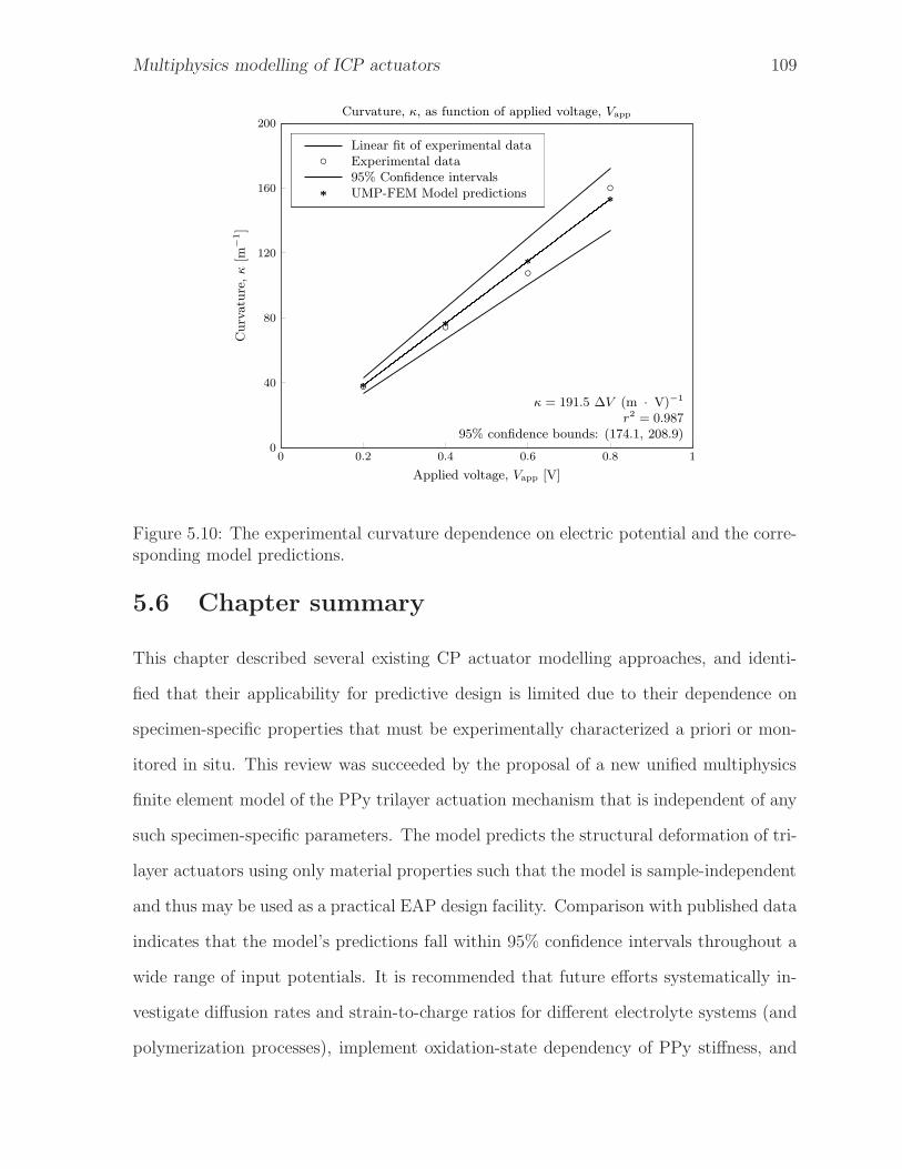
Multiphysics modelling of ICP actuators 109
0 0.2 0.4 0.6 0.8 10
40
80
120
160
200
Applied voltage, Vapp [V]
Curvature,κ[m
−1]
Curvature, κ, as function of applied voltage, Vapp
bC
bC
bC
bC
*
*
*
*
Linear fit of experimental dataExperimental data95% Confidence intervalsUMP-FEM Model predictions
bC
*
κ = 191.5 ∆V (m · V)−1
r2 = 0.98795% confidence bounds: (174.1, 208.9)
Figure 5.10: The experimental curvature dependence on electric potential and the corre-sponding model predictions.
5.6 Chapter summary
This chapter described several existing CP actuator modelling approaches, and identi-
fied that their applicability for predictive design is limited due to their dependence on
specimen-specific properties that must be experimentally characterized a priori or mon-
itored in situ. This review was succeeded by the proposal of a new unified multiphysics
finite element model of the PPy trilayer actuation mechanism that is independent of any
such specimen-specific parameters. The model predicts the structural deformation of tri-
layer actuators using only material properties such that the model is sample-independent
and thus may be used as a practical EAP design facility. Comparison with published data
indicates that the model’s predictions fall within 95% confidence intervals throughout a
wide range of input potentials. It is recommended that future efforts systematically in-
vestigate diffusion rates and strain-to-charge ratios for different electrolyte systems (and
polymerization processes), implement oxidation-state dependency of PPy stiffness, and

Multiphysics modelling of ICP actuators 110
investigate the implications of externally applied loads on the actuation behaviour. This
chapter addresses the prescribed research objective of modelling the ICP trilayer actua-
tion mechanism.
List of references
Alici, G. (2009), ‘An effective modelling approach to estimate nonlinear bending be-
haviour of cantilever type conducting polymer actuators’, Sens. and Actuators, B:
Chemical 141(1), 284–292.
Alici, G. and Huynh, N. (2007), ‘Performance quantification of conducting polymer actu-
ators for real applications: A microgripping system’, IEEE-ASME T. Mech. 12(1), 73–
84.
Alici, G. and Huynh, N. N. (2006), ‘Predicting force output of trilayer polymer actuators’,
Sens. Actuators, A 132(2), 616–625.
Alici, G., Metz, P. and Spinks, G. M. (2005), ‘A mathematical model to describe bending
mechanics of polypyrrole (PPy) actuators’, Proc. 2005 IEEE/ASME Int. Conf. Adv.
Intell. Mechatronics pp. 1029–1034.
Alici, G., Metz, P. and Spinks, G. M. (2006), ‘A methodology towards geometry op-
timization of high performance polypyrrole (PPy) actuators’, Smart Mater. Struct.
15(2), 243–252.
Alici, G., Mui, B. and Cook, C. (2006), ‘Bending modeling and its experimental verifica-
tion for conducting polymer actuators dedicated to manipulation applications’, Sens.
and Actuators, A 126(2), 396–404.
Baum, J. E. (2007), Diffusion coefficients, in C. Zoski, ed., ‘Handbook of Elecrochem-
istry’, Elsevier, Amsterdam, chapter 19.

Multiphysics modelling of ICP actuators 111
Brochu, P. and Pei, Q. (2010), ‘Advances in dielectric elastomers for actuators and arti-
ficial muscles’, Macromolecular Rapid Communications 31(1), 10–36.
Chernov, N. (2010), Circular and Linear Regression, CRC Monographs on Statistics &
Applied Probability, CRC Press, Abingdon.
Della Santa, A., De Rossi, D. and Mazzoldi, A. (1997), ‘Characterization and modelling
of a conducting polymer muscle-like linear actuator’, Smart Mater. Struct. 6(1), 23–34.
Fang, Y., Pence, T. J. and Tan, X. (2008), ‘Nonlinear elastic modeling of differential ex-
pansion in trilayer conjugated polymer actuators’, Smart Mater. Struct. 17(6), 065020.
Fang, Y., Tan, X. and Alici, G. (2008), ‘Robust adaptive control of conjugated polymer
actuators’, IEEE T Contr Syst T 16(4), 600–612.
Fang, Y., Tan, X., Shen, Y., Xi, N. and Alici, G. (2008), ‘A scalable model for trilayer
conjugated polymer actuators and its experimental validation’, Mater. Sci. Eng., C
28(3), 421–428.
John, S., Alici, G. and Cook, C. (2008), ‘Validation of resonant frequency model for poly-
pyrrole trilayer actuators’, IEEE/ASME Transactions on Mechatronics 13(4), 401–409.
Madden, J. (2000), Conducting polymer actuators, MIT PhD Thesis.
Madden, J. D. (2007), Polypyrrole actuators: Properties and initial applications, in K. J.
Kim and S. Tadokoro, eds, ‘Electroactive Polymers for Robotic Applications: Artificial
Muscles and Sensors’, Springer, London, pp. 121–152.
Madden, J. D. W., Madden, P. G. A. and Hunter, I. W. (2001), ‘Polypyrrole actuators:
Modelling and performance’, SPIE Smart Structures and Materials 2001: Electroactive
Polymer Actuators and Devices (EAPAD) 4329, 72–83.
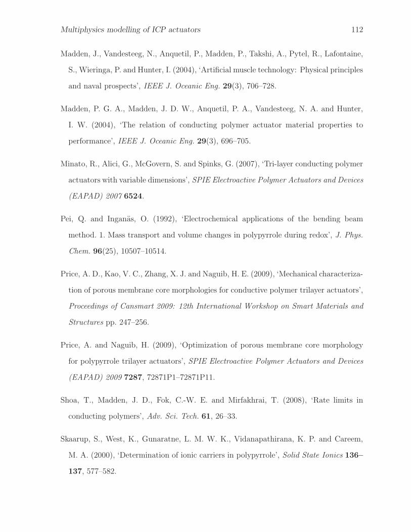
Multiphysics modelling of ICP actuators 112
Madden, J., Vandesteeg, N., Anquetil, P., Madden, P., Takshi, A., Pytel, R., Lafontaine,
S., Wieringa, P. and Hunter, I. (2004), ‘Artificial muscle technology: Physical principles
and naval prospects’, IEEE J. Oceanic Eng. 29(3), 706–728.
Madden, P. G. A., Madden, J. D. W., Anquetil, P. A., Vandesteeg, N. A. and Hunter,
I. W. (2004), ‘The relation of conducting polymer actuator material properties to
performance’, IEEE J. Oceanic Eng. 29(3), 696–705.
Minato, R., Alici, G., McGovern, S. and Spinks, G. (2007), ‘Tri-layer conducting polymer
actuators with variable dimensions’, SPIE Electroactive Polymer Actuators and Devices
(EAPAD) 2007 6524.
Pei, Q. and Inganas, O. (1992), ‘Electrochemical applications of the bending beam
method. 1. Mass transport and volume changes in polypyrrole during redox’, J. Phys.
Chem. 96(25), 10507–10514.
Price, A. D., Kao, V. C., Zhang, X. J. and Naguib, H. E. (2009), ‘Mechanical characteriza-
tion of porous membrane core morphologies for conductive polymer trilayer actuators’,
Proceedings of Cansmart 2009: 12th International Workshop on Smart Materials and
Structures pp. 247–256.
Price, A. and Naguib, H. (2009), ‘Optimization of porous membrane core morphology
for polypyrrole trilayer actuators’, SPIE Electroactive Polymer Actuators and Devices
(EAPAD) 2009 7287, 72871P1–72871P11.
Shoa, T., Madden, J. D., Fok, C.-W. E. and Mirfakhrai, T. (2008), ‘Rate limits in
conducting polymers’, Adv. Sci. Tech. 61, 26–33.
Skaarup, S., West, K., Gunaratne, L. M. W. K., Vidanapathirana, K. P. and Careem,
M. A. (2000), ‘Determination of ionic carriers in polypyrrole’, Solid State Ionics 136–
137, 577–582.

Multiphysics modelling of ICP actuators 113
Suarez, I., Otero, T. and Marquez, M. (2005), ‘Diffusion coefficients in swelling poly-
pyrrole: Escr and cottrell models’, J. Phys. Chem. B 109(5), 1723–1729.
Wang, X., Shapiro, B. and Smela, E. (2006), ‘Modeling charge transport in conjugated
polymers’, SPIE Smart Structures and Materials 2006: Electroactive Polymer Actua-
tors and Devices (EAPAD) 6168, 61680U.
Wang, X., Shapiro, B. and Smela, E. (2009), ‘Development of a model for charge transport
in conjugated polymers’, J. Phys. Chem. C 113(1), 382–401.
Wang, X. and Smela, E. (2009), ‘Experimental studies of ion transport in PPy(DBS)’,
J. Phys. Chem. C 113(1), 369–381.
Wypych, G. (2008), Knovel Solvents - A Properties Database, ChemTec Publishing.

Chapter 6Conductive electroactive polymer actuators
for tilt compensation in active optical
components
Adaptive optical systems incorporate active components that compensate for
wavefront aberrations introduced by optical defects. The quality of optical
compensation is largely determined by the stroke of the adaptive compo-
nent’s underlying actuating mechanism. Development of compact polypyrrole trilayer
actuator arrays may deliver superior performance over conventional active technologies
such as electrostatic electrodes or piezoelectric actuators. This study introduces a novel
piston-tilt mirror apparatus that utilizes low-voltage electroactive polymer actuators to
reorient a plane mirror. The electroactive polymer synthesis procedure and actuator
fabrication method are first reported, followed by the requisite power supply and con-
trol interface design. Finally, laser beam steering results are provided in the context of
an experimental retinal imaging system. The outcomes indicate a promising future for
electroactive polymer-enabled devices in adaptive optical systems with technological im-
plications ranging from more powerful astronomical telescopes to improved retinal tissue
diagnosis.
114

EAP for active optics 115
6.1 EAP actuators and adaptive optics
Images captured by optical systems may be limited in quality by aberrations inherent
to the system, environment, and subject. Aberrations such as defocus and astigmatism
can readily be corrected with lenses while the aberrations are static; however, the source
of certain aberrations is frequently dynamic in nature which limits the effectiveness of
the corrective lenses (Hofer et al., 2001). In these cases, image quality may be greatly
improved by the introduction of an adaptive optical component (Liang et al., 1997).
Adaptive optics systems require a wavefront correcting component such as a de-
formable surface mirror. Several such mirrors based on conventional electromechanical
actuation technologies are commercially available; however the combination of stringent
operational and quality-control requirements result in a product that is prohibitively ex-
pensive for widespread adoption. It has been demonstrated that EAP, and in particular
ICP actuators, are capable of large-strain displacements in the absence of substantial
blocking forces (Hara et al., 2006; McGovern et al., 2009; Price et al., 2008; Price and
Naguib, 2009; Price et al., 2009). In addition, Edward et al. (2006) have demonstrated
the successful miniaturization of mechanically simple ICP actuators in microelectrome-
chanical systems (MEMS) technology. Thus, the development of PPy ICP trilayer actu-
ator arrays may deliver comparable performance at reduced cost and space with respect
to conventional adaptive optics actuator technologies such as electrostatic electrodes or
piezoelectric actuators.
Tyson (2000) states that for many imaging applications considerable wavefront im-
provement can be achieved solely by tilt compensation, in which a plane mirror with
variable orientation is placed in the optical path and used to stabilize the image dynami-
cally. Therefore, this investigation proposes the prototypical design of a novel piston-tilt
mirror mechanism based on conducting electroactive polymer actuators. The concept
demonstrator utilizes four independent low-voltage electroactive polymer actuators ar-
ranged in a planar radial (polar) array to reorient a first-surface plane mirror in piston
EAP for active optics 116
ElectropolymerizedPPy layers
Sputter deposited Ptlayers at interface
Porous PVDFmembrane core
Figure 6.1: The trilayer cross-section consists of a platinum-coated porous membranecore with PPy coatings on the opposing faces of the core.
and tilt deformation modes. The structure of the study is as follows: the electroactive
polymer synthesis procedure and actuator fabrication method are first reported, followed
by the requisite power supply and control interface design, and finally laser beam steering
results are provided in the context of an experimental retinal imaging system.
6.1.1 Conducting polymer actuators
As introduced in Chapter 2, ICP materials such as PPy and PAni have garnered sig-
nificant research interest in recent years as an alternative actuation technology because
they possess many favourable advantages over conventional mechanical actuator technolo-
gies (Smela, 2003). It was shown in Chapter 4 that the strain output of ICP actuators
can be amplified by employing layered configurations that bend. Trilayer actuator ar-
rangements were also shown to be particularly desirable due to the electrolyte storage
function of their central membrane core, as shown in Figure 6.1. This semi-encapsulated
configuration permits the actuator to operate outside of an external electrolyte solu-
tion until evaporative effects limit the ion migration capacity of the internally contained
electrolyte (Otero and Sansinena, 1995).

EAP for active optics 117
6.1.2 Stroke requirement for piston-tilt mirrors
Doble and Williams (2004) have reported a summary of ideal deformable mirror perfor-
mance requirements for vision-science applications and prescribe a minimum piston-mode
stroke of 12 µm in the absence of tip-tilt preconditioning, and a tilt-mode stroke require-
ment of 2 mrad can be approximated from the prescribed parameters.
Angular stroke requirements specific to tilt mirrors for vision-science applications are
not explicitly well-documented; however Tyson (2000) provides a derivation of the angular
stroke requirement for tilt mirrors implemented in adaptive optics systems to correct for
atmospheric turbulence in terrestrial telescopes. The standard deviation attributed to
the atmospheric tilt occurring in the incident wavefront is given by:
σtilt =
√
0.184
(D
r0
)5/3 (λ
D
)2
, (6.1)
where D is the aperture diameter of the primary mirror, r0 is Fried’s coherent length
(a measure of the impact of atmospheric turbulence on the coherence of the incoming
light), and λ is the wavelength of the light. Assuming that most of the tilt disturbance
lies within Mtilt = ±2.5σtilt (Tyson and Frazier, 2004), and noting that the actual angular
mirror stroke results in double the tilt motion of the reflected beam, the required angular
stroke is given by:
Stroke =1
2Mtilt
D
Dtilt
, (6.2)
where Dtilt is the diameter of the beam incident on the tilt mirror. For performance com-
parison purposes, commercially available piston-tilt mode platforms actuated by piezo-
electric actuators (Physik Instrumente, S-323 and S-325) are capable of mechanical tilt
ranging from 1.5-5 mrad(optical tilt of 3-10 mrad) in addition to a piston mode displace-
ment of 30 µm with response times below 1 ms.
EAP for active optics 118
6.2 Fabrication method for trilayer EAP actuators
EAP trilayer actuators are prepared by depositing PPy layers onto a central membrane
core by means of an electropolymerization process. A description of the relevant growth
mechanisms and reaction parameter considerations is provided in section 4.2.2. The
method used to prepare the actuator for this study is herein described: a 63 µm thick
PVDF membrane (Westran CS, #10485288, Whatman) is sputter-coated with platinum
to achieve a conductive coating approximately 10 nm thick. Py was subsequently distilled
at 131 ◦C and preserved in a dark and inert environment. The monomer was polymer-
ized via a multi-step electrochemical oxidation reaction as described in Chapter 4. The
polymerization reaction was performed within the custom-designed electrochemical cell
shown in Figure 4.6(c), wherein the coated membrane acted as the working electrode
and two stainless-steel plates were utilized as counter-electrodes. Electric current was
supplied using a Keithley 2400 Sourcemeter.
In this study, each Pt-coated sheet is immersed in an electrolyte solution based on
PC, 0.2 M LiTFSI, 0.3 M Py, and 1% (w/w) water at −30 ◦C (all chemicals supplied by
Sigma-Aldrich). A current density of 0.3 mA · cm−2 is then applied for 6 h to deposit
electropolymerized PPy films approximately 2 µm thick onto the exposed membrane
surface. The sheets are then rinsed with acetone, and the edges of the trilayer sheet
are trimmed to maintain electrical isolation of the faces. The sheet is subsequently cut
into actuator strips measuring 15 mm long × 8 mm wide to yield multiple actuators
synthesized under uniform conditions. The individual trilayer actuator strips are then
stored in a PC solution containing 0.2 M LiTFSI to prevent drying.
6.3 Design of an EAP piston-tilt mirror
The EAP piston-tilt mirror is designed to integrate into an existing experimental optics
system developed by Ficocelli and Ben Amara (2008) as illustrated in Figure 6.2. The

EAP for active optics 119
DAQ
Laser
ApertureStop
ApertureStop
ApertureStop
WavefrontSensor
EAP Actuated Mirror
Subject
PMUSCU
Tip-tilt mirror
Figure 6.2: The fundamental elements of the experimental optics system consist of acollimated light source, optical relays, an EAP actuated mirror, a wavefront sensor, anda data acquisition system.
ultimate goal of the apparatus is to evaluate new technologies for retinal diagnosis. The
system consists of three primary components: a wavefront sensor, a data acquisition com-
puter, and an active optical component (in this instance the EAP actuated tilt mirror).
Wavefront measurement approaches such as interferometry and the Shack-Hartmann
technique are well-established, and several control methods have been proposed (Fico-
celli and Ben Amara, 2008; Zhu et al., 1999). The focus of this investigation is the design
and demonstration of the EAP piston-tilt mirror prototype.
The ultimate application of conductive polymer materials for the most general case of
a continuously deformable membrane mirror requires that the surface morphology of the
polymerized structure is relatively smooth to permit light to be reflected in a coherent
manner. A stereomicroscope image of the PPy film produced via the electrodeposition of

EAP for active optics 120
Figure 6.3: The metallized polymerization product is inherently porous (particularly onthe electrode side) which is not a suitable surface for optical reflection. The scale bar is1 mm.
polypyrrole onto a metallized acetate substrate is shown in Figure 6.3. Delamination of
the PPy film from the substrate was induced via storage in PC solution, which transferred
the metallic coating to the conductive polymer film. Subsequent microscopy analysis of
the film indicates that the resulting polymerization product is inherently porous and
confirms that the surface roughness is not directly suitable for light reflection. This
obstacle is circumvented in this study by the integration of conductive polymer trilayer
actuators as positioning elements for a conventional (rigid) optical quality mirror, hence
permitting optical corrections that correspond to the rigid body modes of the mirror.
The system consists of several modules in addition to the EAP actuator array and
mirror, namely a power management unit (PMU) which conditions the external power
source for input to the low-voltage EAP actuators and a switching control unit (SCU)
which facilitates the distribution of the input power to the desired actuators in the array

EAP for active optics 121
AC-DC
Transformer120V 10 µF
−
+
5V
L1085-3.3
Regulator
10 µF
−
+
3.3V
A
B
PS Conditioning Unit
Figure 6.4: Schematic representation of the power management unit for the EAP actuatedpiston-tilt mirror.
at the desired polarity. This modular design facilitates system extensibility and rapid
reconfiguration; for example, a portable battery powered PMU can be readily substituted
when system portability is required. A schematic representation of the PMU for the EAP
piston-tilt mirror system is illustrated in Figure 6.4. Power for the EAP actuator array
is provided from the mains supply (120 V AC), which is then reduced by the step-down
transformer and rectified into a 5 V DC signal. The signal is again reduced by a voltage
regulator and filtered to 3.3 V. Motivation for selecting this voltage is two-fold: first,
driving voltages in this range permit a favourable balance of cycle-lifetime and actuation
performance. Second, the 3.3 V threshold is a common open-circuit potential of high-
energy density lithium-ion batteries, so that system miniaturization may be attained in
the future without the need for additional power conversion between a portable battery
and the actuator supply.
Each actuator in the array is individually addressed via the double-pole double-throw
four-way switch arrangement within the SCU module (Figure 6.5). In this implementa-
tion, actuators have three discrete activation states: fully off, full-scale positive polarity,
and full-scale negative polarity. The system may be extended using linear amplifiers to
realize proportional operation and control. The switched polarity of the input signal
is then relayed to the conductive surfaces of the EAP actuators via spring-loaded elec-
trodes, which ensure electrical contact. Figure 6.6 depicts the circular array of four
electroactive polymer actuators within the EAP piston-tilt mirror unit. The actuators

EAP for active optics 122
AOpen
B
Polarity Control Circuit
×4
Fuse
Transmission
×4
xxxxxxxxxxxxxxxxxxxxxxxxxxxxxxxxxxxxxxxxxxxxxxxxxxxxxxxxxxxxxxxx
xxxxxxxxxxxxxxxxxxxxxxxxxxxxxxxxxxxxxxxxxxxxxxxx
Electrodes
EAP Actuator
FS Mirror
Radially symmetric array
Beam Steering Array
Incident radiation
Figure 6.5: Schematic representation of the switching control unit and EAP actuatedpiston-tilt mirror.
in the array are referred to by their respective cardinal directions: north (N), east (E),
south (S), and west (W). Beam reflection and steering is achieved by mounting a 15 mm
diameter first-surface mirror (Edmund Optics, NT32-943, m = 1.333 g) on the free ends
of the trilayer actuators. First-surface mirrors have their reflective coating on the face
the incident light impinges on, such that the light does not propagate through the mirror
substrate. Employing such a mirror eliminates spurious faint reflections typically en-
countered with conventional second surface mirrors where the incident light is partially
reflected by the transparent substrate. Systematic activation of each actuator facilitates
three distinct degrees of freedom useful for optical alignment and tilt-compensation: two
tilt rotations (θx, θy) when one or more actuators are activated in an unbalanced manner,
and a normal displacement (piston mode, z) when one or both pairs of opposing actuators
are simultaneously activated. The complete beam steering apparatus consisting of the
PMU module, SCU module and the EAP mirror actuator array is shown in Figure 6.7.
6.4 Experimental performance characterization
The performance of the EAP piston-tilt mirror is characterized using a Shack-Hartmann
wavefront sensor as indicated in Figure 6.8. The sensor operates on the principle that the

EAP for active optics 123
a
b
c
d
e
Figure 6.6: (a) Electric power delivered from the PMU via the (b) fuse bank is fed tothe (c) contact electrodes. The centrally located (d) first-surface mirror is supported bythe radial EAP actuator array consisting of four (e) trilayer actuators. Beam steering isachieved by activating one or more actuators to displace the mirror.
a
b
c
Figure 6.7: The complete EAP piston-tilt mirror apparatus consists of an integrated(a) PMU, (b) SCU and (c) EAP actuated mirror assembly.

EAP for active optics 124
Focal Length
SpotDeviation
2DDetector
Lenslet Array
Lenslet FocalSpot Pattern
AbberatedWavefront
Figure 6.8: The Shack-Hartmann type wavefront sensor produces a pattern a spots onan optical detector (adapted from Platt and Shack, 2001). The deviation of the spotcentroid from the lenslet spacing is proportional to the local wavefront slope.
centroids of the spots projected through the lenslet array onto the image plane form a
regular grid in the absence of wavefront aberration, and in the presence of an aberration
the amount of tilt (planar wavefront deviation, or wavefront slope) is directly propor-
tional to the displacement of the spot. These local displacements are then numerically
integrated to reconstruct the full wavefront shape.
The Shack-Hartmann sensor implemented in this study (Imagine Optic, HASO™ 32)
samples the wavefront via a 32 × 32 array of miniature lenslets (Platt and Shack, 2001;
Tyson, 2000). Each lenslet projects a focused spot onto an intensity sensitive surface,
which in this case is a CCD camera detector (Toshiba Teli Corp., CS8550i-01) operating at
sampling rates up to 30 Hz. An example spot pattern captured by the detector is shown in
Figure 6.9. The detected image is transmitted by a PCI frame-grabber (Euresys, Domino
Alpha 2™) to a data acquisition computer, where the HASO™ software reconstructs the
wavefront shape from the spot pattern. The calculated wavefront measurements are
further processed using MATLAB to obtain the location of the beam centroid and the
corresponding planes of best-fit for the wavefront data. As the light source is initially

EAP for active optics 125
Figure 6.9: The spot pattern generated by laser light transmitted to the Shack-Hartmannwavefront sensor via the EAP piston-tilt mirror at rest (inverted intensity map depicted).The incident beam area is less than the sensor area which permits tip-tilt translations tobe monitored.
coherent, the relative change in wavefront tilt is an indication of the angular optical
stroke of the mirror. As such, the effect of the actuation mechanism on the optical tilt
can be sensed as shown by the shaded contours in Figure 6.10.
The results indicate that a tilt compensation of 20.6 mrad was achievable using a
single actuator. When adjacent actuators were activated the optical stroke increased
further to 31.9 mrad (corresponding to a mechanical stroke of 16.0 mrad). For alignment
applications, displacement of the beam centroid is an important criteria. In this exper-
iment, the centroid of the sensed beam was laterally deviated 360.5 µm. The optical
path-length between the EAP piston-tilt mirror and the wavefront sensor was 700 mm
and coincides with a de-magnification of 1⁄6. It was not possible to quantify the piston-
mode displacement of the mirror with the current setup due to the differential nature
of the wavefront sensor. A particle tracing analysis of the captured sensor video was
performed using the ImageJ software. The analysis indicates a step-response time on
the order several seconds; however the low frame rate (10 Hz) limits further resolution.
The diffusion based process of the ionic actuation phenomenon limits the time response
of the mirror. However, as the diffusion times of ions scale inversely to the square of
the material thickness (Shoa et al., 2008), additional miniaturization techniques may be
explored to improve the bandwidth of the actuators such that they may compete with
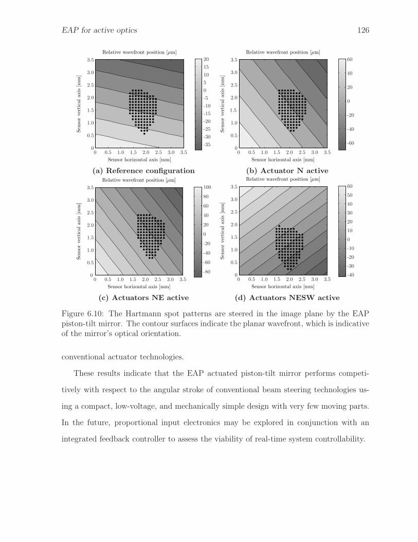
EAP for active optics 126
Sensor horizontal axis [mm]
Sen
sorvertical
axis
[mm]
Relative wavefront position [µm]
0 0.5 1.0 1.5 2.0 2.5 3.0 3.5
-35
-30
-25
-20
-15
-10
-5
0
5
10
15
20
0
0.5
1.0
1.5
2.0
2.5
3.0
3.5
Sensor horizontal axis [mm]
Sen
sorvertical
axis
[mm]
Relative wavefront position [µm]
0 0.5 1.0 1.5 2.0 2.5 3.0 3.5
-60
-40
-20
0
20
40
60
0
0.5
1.0
1.5
2.0
2.5
3.0
3.5
(a) Reference configuration (b) Actuator N active
Sensor horizontal axis [mm]
Sen
sorvertical
axis
[mm]
Relative wavefront position [µm]
0 0.5 1.0 1.5 2.0 2.5 3.0 3.5
-80
-60
-40
-20
0
20
40
60
80
100
0
0.5
1.0
1.5
2.0
2.5
3.0
3.5
Sensor horizontal axis [mm]
Sen
sorvertical
axis
[mm]
Relative wavefront position [µm]
0 0.5 1.0 1.5 2.0 2.5 3.0 3.5-40
-30
-20
-10
0
10
20
30
40
50
60
0
0.5
1.0
1.5
2.0
2.5
3.0
3.5
(c) Actuators NE active (d) Actuators NESW active
Figure 6.10: The Hartmann spot patterns are steered in the image plane by the EAPpiston-tilt mirror. The contour surfaces indicate the planar wavefront, which is indicativeof the mirror’s optical orientation.
conventional actuator technologies.
These results indicate that the EAP actuated piston-tilt mirror performs competi-
tively with respect to the angular stroke of conventional beam steering technologies us-
ing a compact, low-voltage, and mechanically simple design with very few moving parts.
In the future, proportional input electronics may be explored in conjunction with an
integrated feedback controller to assess the viability of real-time system controllability.

EAP for active optics 127
6.5 Chapter summary
This chapter conveyed the development and characterization of an EAP actuated piston-
tilt mirror. The fabrication method for layered electroactive polymer actuators was
conveyed, and the design of an EAP actuator array and ancillary mechatronic systems
were reported. Finally, the angular stroke of the device was characterized in the context
of an experimental retinal diagnosis apparatus. The results indicate a promising future
for EAP-enabled devices in the field of active optical components. This chapter fulfills
the stipulated research objective to demonstrate the novel application of ICP actuators.
List of references
Doble, N. and Williams, D. (2004), ‘The application of MEMS technology for adaptive
optics in vision science’, IEEE J. Quantum Elect. 10(3), 629–635.
Edward, C., Yingkai, L., Smela, E. and Andreou, A. (2006), ‘System for deposition and
characterization of polypyrrole/gold bilayer hinges’, IEEE I. C. Elect. Circ. pp. 3506–
3509.
Ficocelli, M. and Ben Amara, F. (2008), ‘Control system design for retinal imaging
adaptive optics systems’, Proceedings of the American Control Conference pp. 4779–
4784.
Hara, S., Zama, T., Takashima, W. and Kaneto, K. (2006), ‘Tris(trifluoromethylsul-
fonyl)methide-doped polypyrrole as a conducting polymer actuator with large electro-
chemical strain’, Synth. Met. 156(2-4), 351–355.
Hofer, H., Artal, P., Singer, B., Aragon, J. and Williams, D. (2001), ‘Dynamics of the
eye’s wave aberration’, J. Opt. Soc. Am. A 18(3), 497–506.
EAP for active optics 128
Liang, J., Williams, D. and Miller, D. (1997), ‘Supernormal vision and high-resolution
retinal imaging through adaptive optics’, J. Opt. Soc. Am. A 14(11), 2884–2892.
McGovern, S., Alici, G., Truong, V.-T. and Spinks, G. (2009), ‘Finding NEMO (novel
electromaterial muscle oscillator): A polypyrrole powered robotic fish with real-time
wireless speed and directional control’, Smart Mater. Struct. 18(9), 095009.
Otero, T. F. and Sansinena, J. M. (1995), ‘Artificial muscles based on conducting poly-
mers’, Bioelectrochemistry and Bioenergetics 38(2), 411–414.
Platt, B. C. and Shack, R. (2001), ‘History and principles of Shack-Hartmann wavefront
sensing’, J. Refract. Surg. 17(5), S573–S577.
Price, A. D., Kao, V. C., Zhang, X. J. and Naguib, H. E. (2009), ‘Mechanical characteriza-
tion of porous membrane core morphologies for conductive polymer trilayer actuators’,
Proceedings of Cansmart 2009: 12th International Workshop on Smart Materials and
Structures pp. 247–256.
Price, A. D., Liu, C. C., O’Shaughnessy, C. A. and Naguib, H. E. (2008), ‘Characteri-
zation of conductive polymer trilayer actuators for biomimetic robotics’, Proceedings
of Cansmart 2008: 11th International Workshop on Smart Materials and Structures
pp. 325–334.
Price, A. and Naguib, H. (2009), ‘Optimization of porous membrane core morphology
for polypyrrole trilayer actuators’, SPIE Electroactive Polymer Actuators and Devices
(EAPAD) 2009 7287, 72871P1–72871P11.
Shoa, T., Madden, J. D., Fok, C.-W. E. and Mirfakhrai, T. (2008), ‘Rate limits in
conducting polymers’, Adv. Sci. Tech. 61, 26–33.
Smela, E. (2003), ‘Conjugated polymer actuators for biomedical applications’, Adv.
Mater. 15(6), 481–494.

EAP for active optics 129
Tyson, R. K. (2000), Introduction to Adaptive Optics, SPIE, Bellingham, Washington.
Tyson, R. K. and Frazier, B. W. (2004), A Field Guide to Adaptive Optics, SPIE, Belling-
ham, Washington.
Zhu, L., Sun, P.-C., Bartsch, D.-U., Freeman, W. and Fainman, Y. (1999), ‘Adaptive
control of a micromachined continuous-membrane deformable mirror for aberration
compensation’, Appl. Optics 38(1), 168–176.
Chapter 7Concluding remarks
7.1 Summary of conclusions
This thesis explored the issues surrounding the unique electrochemomechanical properties
of ICP to develop innovative engineering materials for novel applications. The experience
gained through these activities has prompted the following conclusions:
1. The porous morphology of thermally-processable polymeric blends consisting of an
electrically conductive PAni-DBSA complex in a PMMA parent phase was explored.
In addition, the impact of the blend composition and underlying microstructure on
the frequency dependent electrical conductivity of the polyblends was elucidated.
Finally, dielectric measurements of a blend composition near the percolation thresh-
old identified the critical dispersion frequency indicative of the transition from a
low-frequency conductor to high-frequency insulator.
2. The actuation phenomena exhibited by conductive polymers was introduced, and
the pertinent synthesis parameters for the fabrication of trilayer actuators were
reviewed. It was shown that mechanical properties of the membrane core were par-
ticularly vital parameters in the optimization of the response, which reinforced the
importance of a deliberate membrane selection process. The mechanical properties
130

Conclusions 131
of several alternative core materials were subsequently characterized based on their
porous morphology, quasi-static stress strain response, and viscoelastic response.
From these results, it was determined that PVDF is the most favourable candidate
material if tip displacement is to be maximized. A PPy electropolymerization pro-
cedure and requisite electropolymerization apparatus were then designed to syn-
thesize CP trilayer actuators. TFSI− doped PPy trilayer actuators with PVDF
cores and nylon cores were fabricated under various synthesis conditions. The elec-
tromechanical actuation response of these actuators was investigated in terms of
charge transport, frequency dependent tip deflection and blocking force. It was
confirmed that higher input electric potentials induced greater bending strains as
a result of the larger counterion charge densities. Tip displacements were observed
to diminish with increasing input electric potential frequency as the elapsed time
between polarity reversals was reduced, which in turn reduced the time available
for charge transport via ionic diffusion and migration. The blocking force gener-
ated by the actuator was shown to be a transient phenomenon that follows the
cyclic input voltage, and indicated that these devices are particularly suitable for
precision positioning applications requiring low force.
3. Conductive polymer actuator modelling approaches were reviewed. The models’
applicability for predictive design was identified as a limitation due to their depen-
dence on specimen-specific properties that must be experimentally characterized
a priori or monitored in situ. A new unified multiphysics finite element model of
the PPy trilayer actuation mechanism was proposed that is independent of any
such specimen-specific parameters. The model predicts the structural deformation
of trilayer actuators using only material properties such that the model is sam-
ple independent and thus may be used as a practical electroactive polymer design
facility. Comparison with published data indicated that the model predictions
fall within 95% confidence intervals throughout a wide range of input potentials.

Conclusions 132
It was recommended that future efforts systematically investigate strain-to-charge
ratios for different electrolyte systems (and polymerization processes), implement
oxidation-state dependency of polypyrrole stiffness, and investigate the implications
of external loads on the actuation behaviour.
4. Finally, the development and characterization of an EAP actuated piston-tilt mir-
ror was conveyed. The method implemented for the fabrication of the layered
electroactive polymer actuators was described, and the design of an EAP actuator
array and ancillary mechatronic systems were reported. Finally, the angular stroke
of the device was characterized in the context of an experimental retinal diagnosis
apparatus. The results indicate a promising future for EAP enabled devices in the
field of active optical components.
7.2 Summary of contributions
The most significant research contributions presented in this thesis are summarized as
follows:
• The first-ever study of novel porous conducting polymer blends was reported. A
new material fabrication method consisting of chemical and thermal processing,
compound extrusion and batch foaming techniques was implemented for the prepa-
ration of wholly polymer blends that uniquely exhibit low mass density and elec-
trical percolation behaviour. Microcellular and dielectric characterization methods
were applied to elucidate the evolution of the porous morphology, and the critical
percolation threshold was identified. Finally, a statistical model of blend conduc-
tivity below the percolation threshold was proposed that accounts for 99.5% of
physical variation in blend conductivity as a function of composition and relative
density.

Conclusions 133
• The first study on the influence of the membrane core elasticity and porous mor-
phology on the actuation response of conducting polymer trilayer bending actua-
tors was reported. Quasi-static and dynamic mechanical analysis experiments are
conducted on candidate core membrane materials to characterize their mechanical
stiffness systematically, and from these results it was determined that PVDF is the
most favourable candidate material if tip displacement is to be maximized. An im-
proved conducting polymer electropolymerization method was proposed, and the
requisite novel reactor vessel design for the low-temperature fabrication of electro-
chemically layered composite structures was realized. This novel actuator fabrica-
tion facility was utilized to prepare trilayer actuators under varying conditions to
assess their resulting morphology. A new actuation characterization apparatus was
commissioned to quantify the electromechanical performance of trilayer actuators
using a laser displacement sensor, digital camera, load cell, signal generator, elec-
trical sourcemeter, and data acquisition computer. The apparatus was utilized to
characterize frequency-dependent electromechanical actuation behaviour in terms
of free tip displacement and blocking force.
• A new unified multiphysics finite element model was introduced that bridges the gap
between existing modelling approaches for the coupled electrical, chemical trans-
port, and mechanical responses of layered conductive polymer actuators. The model
was realized using the COMSOL Multiphysics® commercial software and simula-
tions are conducted to obtain actuator deflection curves in response to a range of
applied voltages. Comparison with published data indicates that the model predic-
tions of mechanical curvature fall within 95% confidence intervals throughout the
entire range of input potentials evaluated.
• A novel piston-tilt mirror apparatus was developed that employs low-voltage elec-
troactive polymer actuators to reorient a plane mirror. The requisite electroactive

Conclusions 134
polymer synthesis procedure and actuator fabrication method were reported, ac-
companied by the original design of the ancillary power management and control
interface units. Finally, the apparatus was experimentally tested for the first time,
and laser beam steering performance results were obtained in the context of an
existing experimental retinal imaging system. The results indicated that a tilt
compensation of 20.6 mrad was achievable using a single actuator, and the optical
stroke increased further to 31.9 mrad when adjacent actuators were activated.
7.3 Scholarly publications associated with this thesis
The research work presented in this thesis has been disseminated via 3 refereed journal
articles, 7 refereed conference papers published in proceedings, 6 podium presentations
at scientific conferences and 1 conference poster presentation detailed as follows:
7.3.1 Refereed journal publications
1. Price, A. D. and Naguib, H. E. (2008), ‘Synthesis and characterization of porous
polyaniline conductive polymers’, Cellular Polymers 27(3), pp. 201–212.
2. Price, A. D., Kao, V. C., Zhang, J. X. and Naguib, H. E. (2010), ‘Fabrication
and percolation behaviour of novel porous conductive polyblends of polyaniline and
poly(methyl methacrylate)’, Synth. Met. 160(17-18), pp. 1832–1837.
3. Price, A. D., Gillen, T., Liu, C. C., O’Shaughnessy, C. A. and Naguib, H. E.
(2011), ‘Evaluation of porous membrane core elasticity and porous morphology for
polypyrrole trilayer actuators’, J. Cell. Plast. 48(1), 25–42.

Conclusions 135
7.3.2 Refereed conference papers published in proceedings
1. Price, A. D., Berndt, C. S., Deluca, J. M., Farra, N., Gillies, A. G., Kopec, M. O.
and Naguib, H. E. (2007), ‘Synthesis and evaluation of ionic electroactive polymer
actuators’, Proceedings of Cansmart 2007: 10th International Workshop on Smart
Materials and Structures, pp. 197–206.
2. Price, A. D., Liu, C. C., O’Shaughnessy, C. A. and Naguib, H. E. (2008), ‘Char-
acterization of conductive polymer trilayer actuators for biomimetic robotics’, Pro-
ceedings of Cansmart 2008: 11th International Workshop on Smart Materials and
Structures, pp. 325–334.
3. Price, A. D., Kao, V. C., Zhang, X. J. and Naguib, H. E. (2009), ‘Mechanical
characterization of porous membrane core morphologies for conductive polymer
trilayer actuators’, Proceedings of Cansmart 2009: 12th International Workshop
on Smart Materials and Structures, pp. 247–256.
4. Price, A. D. and Naguib, H. E. (2007), ‘Synthesis and characterization of porous
polyaniline conductive polymers’, SPIE Electroactive Polymer Actuators and De-
vices (EAPAD) 2007 6524, pp. 65240V-1–65240V-8.
5. Price, A. and Naguib, H. (2008), ‘Porous conductive polyblends of polyaniline in
poly (methyl methacrylate)’, SPIE Electroactive Polymer Actuators and Devices
(EAPAD) 2008 6927, pp. 69271U-1–69271U-10.
6. Price, A. and Naguib, H. (2009), ‘Optimization of porous membrane core mor-
phology for polypyrrole trilayer actuators’, SPIE Electroactive Polymer Actuators
and Devices (EAPAD) 2009 7287, pp. 72871P1–72871P11.
7. Price, A., Naguib, H. and Ben Amara, F. (2010), ‘Development of a deformable
mirror based on conductive polymer actuator arrays for adaptive optics’, SPIE

Conclusions 136
Electroactive Polymer Actuators and Devices (EAPAD) 2010 7642, pp. 76422I1–
76422I9.
7.3.3 Conference presentations
1. Price, A. D., Berndt, C. S., Deluca, J. M., Farra, N., Gillies, A. G., Kopec, M. O.
and Naguib, H. E. (2007), ‘Synthesis and evaluation of ionic electroactive polymer
actuators’, Proceedings of Cansmart 2007: 10th International Workshop on Smart
Materials and Structures, Montreal, October 2007.
2. Price, A. D. and Naguib, H. E. (2007), ‘Synthesis and characterization of porous
polyaniline conductive polymers’, SPIE Electroactive Polymer Actuators and De-
vices (EAPAD) 2007 6524, San Diego, March 2007.
3. Price, A. D., Liu, C. C., O’Shaughnessy, C. A. and Naguib, H. E. (2008), ‘Char-
acterization of conductive polymer trilayer actuators for biomimetic robotics’, Pro-
ceedings of Cansmart 2008: 11th International Workshop on Smart Materials and
Structures, Montreal, October 2008.
4. Price, A. and Naguib, H. (2009), ‘Optimization of porous membrane core mor-
phology for polypyrrole trilayer actuators’, SPIE Electroactive Polymer Actuators
and Devices (EAPAD) 2009 7287, San Diego, March 2009.
5. Price, A. D., Kao, V. C., Zhang, X. J. and Naguib, H. E. (2009), ‘Mechanical
characterization of porous membrane core morphologies for conductive polymer
trilayer actuators’, Proceedings of Cansmart 2009: 12th International Workshop
on Smart Materials and Structures, Montreal, October 2009.
6. Price, A., Naguib, H. and Ben Amara, F. (2010), ‘Development of a deformable
mirror based on conductive polymer actuator arrays for adaptive optics’, SPIE

Conclusions 137
Electroactive Polymer Actuators and Devices (EAPAD) 2010 7642, San Diego,
March 2010.
7.3.4 Poster presentations
1. Price, A. and Naguib, H. (2008), ‘Porous conductive polyblends of polyaniline in
poly (methyl methacrylate)’, SPIE Electroactive Polymer Actuators and Devices
(EAPAD) 2008 6927, San Diego, March 2008.
7.4 Recommendations for future research
The novel conducting polymer foam polyblends introduced in this thesis provide a new
family of low-density conductors that may prove particularly useful for electrostatic dis-
charge protective packaging for shock sensitive components. Further study is required to
determine the long-term stability of the electrical conductivity, particularly for service in
humid environments.
The influence of the mechanical properties of the trilayer actuator membrane core
discussed in Chapter 4 (Fabrication and characterization of polypyrrole trilayer actua-
tors) would be well-complemented by a study on the influence of the chemical transport
properties on actuator performance. Such a study requires an apparatus to accurately
quantify ion transport rates, and empirical measurements of membrane tortuosity and
open area fraction must also be obtained.
The electropolymerization vessel and procedure proposed in Chapter 4 provide a valu-
able facility for future research requiring electro-deposited films on any general substrate.
Such a facility may be used to explore a variety of effects; however the author deems it
most interesting to investigate the impact of substrate morphology on the resulting film;
particularly in terms of common actuator failure modes such as layer delamination and
electrical short-circuiting. The use of microfabrication techniques such as electron beam

Conclusions 138
lithography could enable micro- or perhaps even nanoscale devices to be realized with
rapid response times due to their reduced charge transport path dimensions.
Suggested refinements concerning the unified multiphysics finite element model pro-
posed in Chapter 5 include the modelling of the activation kinetics known to exist (to
account for the unmodelled activation energy barrier). Dedicated experiments to quan-
tify the ion mobility and diffusivity of various electrolytes are required to improve the
accuracy of the strain-to-charge parameter.
Finally, the EAP based adaptive optical system described in Chapter 6 provides a
springboard for the study of existing and novel control algorithms which may permit
closed-loop image correction at a frequency high enough to fulfill the project’s ultimate
goal of retinal image diagnoses.

Appendices
139

Appendix AList of acronyms and symbols
Acronyms
ALE arbitrary Lagrangian-Eulerian, a finite element technique that accommo-dates large mesh distortions
CNT carbon nanotubes
CP conducting polymers, conductive polymers (implied to be intrinsicallyconductive, as opposed to conductive due to the addition of conductingparticles)
CSA camphor sulphonic acid
DBSA dodecylbenzene sulfonic acid
DEM diffusive elastic metal
DMA dynamic mechanical analyzer/analysis
E East
EAP electroactive polymers, electromechanically active polymers
EB Emeraldine base
ECM electrochemomechanical
ES Emeraldine salt
FEA finite element analysis
ICP inherently/intrinsically conductive polymers
IPMC ionomeric polymer-metal composites
LEB Leucoemeraldine base
140

Appendix A. List of acronyms and symbols 141
MEMS microelectromechanical systems
MUMPS multifrontal massively parallel sparse direct solver, a parallel sparse directlinear solver for numerical systems
MW molecular weight
N North
NMP Methylpyrrolidone
PAni polyaniline
PC propylene carbonate
PMMA poly(methyl methacrylate)
PMU power management unit
PPy polypyrrole
PVDF polyvinylidene difluoride
Py pyrrole
S South
SCU switching control unit
TFSI− bis(trifluoromethane)sulfonimide anion
W West
Greek symbols
α strain-to-charge ratio
α∗ voltage-dependent electromechanical proportionality coefficient
δ double-layer thickness
ǫ mechanical strain
ǫ∞ instantaneous dielectric constant
ε0 permittivity of free space, 8.85 pF ·m−1
ǫ′ real component of complex electrical permittivity
ǫ′′ imaginary component of complex electrical permittivity
εr medium dielectric constant

Appendix A. List of acronyms and symbols 142
εr,CP dielectric constant of conducting polymer
εr,electrolyte electrolyte dielectric constant
ǫ∗ complex electrical permittivity
ǫs static dielectric constant
κ curvature of bending actuator
λ wavelength of light
µk ionic mobility of species k
νcore Poisson’s ratio of membrane core
νCP Poisson’s ratio of conducting polymer
φ mass fraction of PAni-DBSA in PMMA (Chapter 3), local electric poten-tial (Chapter 5)
φc critical mass fraction at percolation threshold
ρ relative density of porous material (Chapter 3), local net charge density(Chapter 5)
ρcore mass density of membrane core
ρCP mass density of conducting polymer
ρf density of the specimen in the foamed state
ρp density of the specimen in the unfoamed polymer state
σ mechanical stress
σtilt standard deviation attributed to atmospheric tilt
τ characteristic dielectric relaxation time
θx tilt mirror rotation about x-axis
θy tilt mirror rotation about y-axis
ω angular frequency
ωc critical dispersion frequency
ωc estimate of crossover frequency given by Jager relation
Latin symbols
A area of interest for cellular morphology characterization

Appendix A. List of acronyms and symbols 143
A− Anionic species
ai blend conductivity model coefficient
b actuator width
C double-layer capacitance
C+ Cationic species
CA0,electrolyte initial concentration of anions in electrolyte
CA,electrolyte concentration of anions in electrolyte
CA,electrolyte,max maximum concentration of anions in electrolyte
CC0,electrolyte initial concentration of cations in electrolyte
Ck concentration of species k
CV volumetric capacitance
D foaming gas diffusion coefficient (Chapter 3), diffusivity of mobile ion(Chapter 5), aperture diameter of the primary mirror (Chapter 6)
d spun fibre diameter
d average pore diameter in a cellular material
DA computed IPMC diffusion rate coefficient
DA,Core diffusion coefficient of anions in membrane core
DA,CP diffusion coefficient of anions in conducting polymer
DC,Core diffusion coefficient of cations in membrane core
DC,CP diffusion coefficient of cations in conducting polymer
DH diffusion coefficient of holes in conducting polymer
Dk diffusion coefficient of species k
ds spinneret diameter
Dtilt diameter of the beam incident on the tilt mirror
E polymer stiffness
e− Electron
E1 elastic modulus of PPy in Alici model

Appendix A. List of acronyms and symbols 144
Ecore elastic modulus of membrane core
ECP elastic modulus of conducting polymer
EI flexural rigidity of the layered actuator in Alici model
Enylon elastic modulus of nylon membrane
EPVDF elastic modulus of PVDF membrane
F actuator blocking force
F Faraday constant, 96485.3365 C ·mol−1
H IPMC half-thickness
h foaming specimen thickness (Chapter 3), ionomer half-thickness (Chap-ter 2)
h1 thickness of electropolymerized PPy film
hm porous membrane core thickness
hp CP layer thickness
k index of species under consideration
L IPMC actuator length
LA effective length of anode boundary layer
LC effective length of cathode boundary layer
Lclamped length of trilayer actuator that is clamped
Lfree length of trilayer actuator that is free to bend
m molecular weight of PPy molecule
Mtilt tilt disturbance measure
n the number of pores in a given two-dimensional area (Chapter 3), degreeof oxidation of PPy molecule (Chapter 4)
Np pore density given by number of pore sites per unit of original unfoamedvolume
P+ ICP site at oxidized redox state
P0 ICP site at standard (reduced) redox state
Ps applied fibre spinning pressure

Appendix A. List of acronyms and symbols 145
Q charge density of free anions
Qmol molar concentration of free anionic charge carriers
R electrolyte resistance
r0 Frieds coherent length
t elapsed time
t0 initial time
tA cluster pressure in anode boundary layer
tC cluster pressure in cathode boundary layer
tf foaming time
tsat gas-polymer solution saturation time
u IPMC free tip velocity
v bending actuator deflection coordinate
Vapp applied electric potential
YB elastic modulus of bare ionomer
YBL elastic modulus of IPMC boundary layer
YIPMC elastic modulus of hydrated IPMC
z piston mode mirror displacement
zA valence charge number of anionic species
zC valence charge number of cationic species
ZD impedance associated with ionic charge transport
zH valence charge number of holes
zk valence charge number of species k

Appendix BSoftware code listing
B.1 COMSOL Multiphysics® implementation of the
unified multiphysics finite element model (UMP-
FEM)
Listing B.1: Price UMP FEM Parametric Extension Condensed.m COMSOL ModelDefinition
1 function out = model
%
% Price_UMP_FEM_Parametric_Extension_Condensed.m
%
5 % Model exported on Dec 22 2011, 11:21 by COMSOL 4.2.0.228.
import com.comsol.model.*
import com.comsol.model.util.*
10 model = ModelUtil.create(’Model’);
model.modelPath(’C:\Users\Aaron Price\Dropbox\Price_UMP_FEM’);
model.name(’Price_UMP_FEM_Parametric_Extension_Condensed.mph’);
15
model.author(’Aaron Price’);
model.param.set(’param_V’, ’4’, ’Voltage parameter’);
model.param.set(’V_app’, ’0.2[V]* param_V’, ’Applied electric potential’
);
20 model.param.set(’h_cp’, ’50[um]’, ’PPy layer thickness’);
model.param.set(’h_core ’, ’110[um]’, ’PVDF core thickness’);
model.param.set(’b’, ’1[mm]’, ’Actuator width’);
model.param.set(’t0’, ’0’, ’Initial simulation time [s]’);
model.param.set(’dt’, ’0.1’, ’Time step to store solutions’);
25 model.param.set(’tf’, ’500’, ’Final simulation time [s]’);
model.param.set(’T’, ’273[K]’, ’Ambient temperature’);
146

Software code listing 147
model.param.set(’D_A’, ’2e -10[m^2/s]’, ’Anion diffusivity in CP layer’)
;
model.param.set(’D_H’, ’D_A’, ’Hole diffusivity’);
model.param.set(’D_C’, ’D_A/100’, ’Cation diffusivity in CP layer ’);
30 model.param.set(’D_A_E’, ’D_A*1e3’, ’Anion diffusivity in solvent’);
model.param.set(’D_C_E’, ’D_A_E /10’, ’Cation diffusivity in solvent’);
model.param.set(’mu_A’, ’D_A*e_const/(k_B_const*T)/F_const’, ’Anion
mobility in CP layer’);
model.param.set(’mu_H’, ’D_H*e_const/(k_B_const*T)/F_const’, ’Hole
mobility’);
model.param.set(’mu_C’, ’D_C*e_const/(k_B_const*T)/F_const’, ’Cation
mobility in CP layer’);
35 model.param.set(’mu_A_E ’, ’D_A_E*e_const/( k_B_const*T)/F_const’, ’Anion
mobility in solvent’);
model.param.set(’mu_C_E ’, ’D_C_E*e_const/( k_B_const*T)/F_const’, ’
Cation mobility in solvent’);
model.param.set(’epsilon_r_solvent’, ’64.92’, ’Relative permittivity of
solvent (PC) [Knovel Properties DB]’);
model.param.set(’L1’, ’10[mm]’, ’Free actuator length ’);
model.param.set(’L2’, ’5[mm]’, ’Clamped actuator length ’);
40 model.param.set(’A_cp_film’, ’b*(L1+L2)’, ’Cross sectional area of film
’);
model.param.set(’V_cp_film’, ’A_cp_film*h_cp’, ’Volume of film’);
model.param.set(’C0’, ’7.86e-7[F/mm^2]’, ’Double -layer capacitance per
unit area [Y. Fang , 2008]’);
model.param.set(’delta’, ’25[nm]’, ’Thickness of double layer [Y. Fang ,
2008]’);
model.param.set(’c_V’, ’C0/delta ’, ’Specific volumetric capacitance [
Madden]’);
45 model.param.set(’Q’, ’c_V*V_app’, ’Effective liberated ionic charge
concentration’);
model.param.set(’Q_mol’, ’Q/F_const’, ’Effective hole concentration’);
model.param.set(’C_E’, ’0.25[mol/L]’, ’Electrolyte concentration (TBA -
PF6) [G. Alici , "Bending modeling and its experimental...", 2006]’);
model.param.set(’Anions_E0’, ’C_E’, ’Initial electrolyte concentrations
’);
model.param.set(’Cations_E0’, ’C_E’, ’Initial electrolyte
concentrations’);
50 model.param.set(’Anions_C0’, ’C_E+Q_mol’, ’Initial concentrations’);
model.param.set(’Cations_C0’, ’C_E’, ’Initial concentrations’);
model.param.set(’Holes_C0’, ’Q_mol’, ’Initial concentrations’);
model.param.set(’Anions_A0’, ’C_E’, ’Initial concentrations’);
model.param.set(’Cations_A0’, ’C_E’, ’Initial concentrations’);
55 model.param.set(’Holes_A0’, ’0’, ’Initial concentrations’);
model.param.set(’Mk’, ’1e4[m/s]’, ’Stiff -spring Flux Constant’);
model.param.set(’Anions_max’, ’C_E+Q_mol’, ’Solubility limit’);
model.param.set(’Cations_max’, ’Anions_max’, ’Solubility limit’);
model.param.set(’Anions_E_max’, ’6[mol/L]’, ’Solubility limit’);
60 model.param.set(’Cations_E_max’, ’Anions_E_max’, ’Solubility limit’);
model.param.set(’X_midplane’, ’h_cp +0.5* h_core ’, ’Geometric mid -plane
coordinate’);
model.param.set(’E_cp’, ’80[MPa]’, ’Elastic stiffness’);
model.param.set(’E_core ’, ’440[MPa]’, ’Elastic stiffness’);
model.param.set(’rho_cp ’, ’1150[ kg/m^3]’, ’Mass density’);

Software code listing 148
65 model.param.set(’rho_core’, ’1150[kg/m^3]’, ’Mass density’);
model.param.set(’nu_cp’, ’0.25’, ’Poisson’’s ratio’);
model.param.set(’nu_core’, ’0.25’, ’Poisson’’s ratio’);
model.param.set(’z_A’, ’-1’, ’Anion valence’);
model.param.set(’z_C’, ’1’, ’Cation valence’);
70 model.param.set(’z_H’, ’1’, ’Hole valence’);
model.param.set(’alpha_l_cp0’, ’1.3e-10[m^3/C]’, ’Strain-to-charge
ratio initial guess’);
model.param.set(’k’, ’14.888 ’, ’Strain -to -charge parameter’);
model.param.set(’alpha_l_cp’, ’alpha_l_cp0*k’, ’Actual strain -to -charge
ratio’);
model.param.set(’beta_cp’, ’alpha_l_cp*E_cp’, ’Stress-to-charge ratio’)
;
75 model.param.set(’strain_linear’, ’alpha_l_cp*c_V*V_app’, ’Induced
linear strain ’);
model.modelNode.create(’mod1’);
model.modelNode.create(’mod2’);
model.modelNode(’mod1’).name(’Charge Transport Model’);
80 model.modelNode(’mod2’).name(’Solid Mechanics Model’);
model.func.create(’step1’, ’Step’);
model.func.create(’step2’, ’Step’);
model.func(’step1’).model(’mod1’);
85 model.func(’step1’).name(’Species Saturation’);
model.func(’step1’).set(’location’, ’(C_E+0.5* Q_mol)/(C_E+Q_mol)’);
model.func(’step1’).set(’from’, ’1’);
model.func(’step1’).set(’to’, ’0’);
model.func(’step1’).set(’smooth ’, ’Q_mol/(C_E+Q_mol)’);
90 model.func(’step2’).model(’mod1’);
model.func(’step2’).name(’Flux Saturation’);
model.func(’step2’).set(’location’, ’(C_E+0.5* Q_mol)/(C_E+Q_mol)’);
model.func(’step2’).set(’from’, ’1’);
model.func(’step2’).set(’to’, ’0’);
95 model.func(’step2’).set(’smooth ’, ’Q_mol/(C_E+Q_mol)’);
model.geom.create(’geom1’, 1);
model.geom(’geom1’).model(’mod1’);
model.geom(’geom1’).lengthUnit([ native2unicode(hex2dec(’00b5’), ’Cp1252
’) ’m’]);
100 model.geom(’geom1’).feature.create(’i1’, ’Interval’);
model.geom(’geom1’).feature.create(’i2’, ’Interval’);
model.geom(’geom1’).feature.create(’i3’, ’Interval’);
model.geom.create(’geom2’, 2);
model.geom(’geom2’).lengthUnit([ native2unicode(hex2dec(’00b5’), ’Cp1252
’) ’m’]);
105 model.geom(’geom2’).feature.create(’r1’, ’Rectangle’);
model.geom(’geom2’).feature.create(’r2’, ’Rectangle’);
model.geom(’geom2’).feature.create(’r3’, ’Rectangle’);
model.geom(’geom2’).feature.create(’r4’, ’Rectangle’);
model.geom(’geom2’).feature.create(’r5’, ’Rectangle’);
110 model.geom(’geom2’).feature.create(’r6’, ’Rectangle’);
model.geom(’geom2’).feature.create(’b1’, ’BezierPolygon’);
model.geom(’geom2’).feature.create(’pt1’, ’Point’);

Software code listing 149
model.geom(’geom2’).feature.create(’b2’, ’BezierPolygon’);
model.geom(’geom2’).feature.create(’arr1’, ’Array’);
115 model.geom(’geom2’).feature.create(’pt2’, ’Point’);
model.geom(’geom2’).feature.create(’pt3’, ’Point’);
model.geom(’geom2’).feature.create(’pt4’, ’Point’);
model.geom(’geom2’).feature.create(’pt5’, ’Point’);
model.geom(’geom2’).feature.create(’pt6’, ’Point’);
120 model.geom(’geom2’).feature.create(’pt7’, ’Point’);
model.geom(’geom2’).feature.create(’pt8’, ’Point’);
model.geom(’geom2’).feature.create(’pt9’, ’Point’);
model.geom(’geom2’).feature.create(’pt10’, ’Point’);
model.geom(’geom2’).feature.create(’pt11’, ’Point’);
125 model.geom(’geom1’).feature(’i1’).set(’p2’, ’h_cp’);
model.geom(’geom1’).feature(’i2’).set(’p1’, ’h_cp’);
model.geom(’geom1’).feature(’i2’).set(’p2’, ’h_cp+h_core ’);
model.geom(’geom1’).feature(’i3’).set(’p1’, ’h_cp+h_core ’);
model.geom(’geom1’).feature(’i3’).set(’p2’, ’2*h_cp+h_core ’);
130 model.geom(’geom1’).run;
model.geom(’geom2’).feature(’r1’).set(’size’, {’h_cp’ ’L1’});
model.geom(’geom2’).feature(’r2’).set(’pos’, {’h_cp’ ’0’});
model.geom(’geom2’).feature(’r2’).set(’size’, {’h_core ’ ’L1’});
model.geom(’geom2’).feature(’r3’).set(’pos’, {’h_cp+h_core ’ ’0’});
135 model.geom(’geom2’).feature(’r3’).set(’size’, {’h_cp’ ’L1’});
model.geom(’geom2’).feature(’r4’).set(’pos’, {’0’ ’L1’});
model.geom(’geom2’).feature(’r4’).set(’size’, {’h_cp’ ’L2’});
model.geom(’geom2’).feature(’r5’).set(’pos’, {’h_cp’ ’L1’});
model.geom(’geom2’).feature(’r5’).set(’size’, {’h_core ’ ’L2’});
140 model.geom(’geom2’).feature(’r6’).set(’pos’, {’h_cp+h_core ’ ’L1’});
model.geom(’geom2’).feature(’r6’).set(’size’, {’h_cp’ ’L2’});
model.geom(’geom2’).feature(’b1’).set(’p’, {’X_midplane’ ’X_midplane’;
’0’ ’L1’});
model.geom(’geom2’).feature(’b1’).set(’degree ’, {’1’});
model.geom(’geom2’).feature(’b1’).set(’w’, {’1’ ’1’});
145 model.geom(’geom2’).feature(’pt1’).set(’p’, {’X_midplane’; ’0’});
model.geom(’geom2’).feature(’b2’).set(’p’, {’h_cp’ ’h_cp+h_core ’; ’L1
/10’ ’L1/10’});
model.geom(’geom2’).feature(’b2’).set(’degree ’, {’1’});
model.geom(’geom2’).feature(’b2’).set(’w’, {’1’ ’1’});
model.geom(’geom2’).feature(’arr1’).set(’size’, ’9’);
150 model.geom(’geom2’).feature(’arr1’).set(’type’, ’linear ’);
model.geom(’geom2’).feature(’arr1’).set(’displ’, {’0’ ’L1/10’});
model.geom(’geom2’).feature(’arr1’).selection(’input’).set({’b2’});
model.geom(’geom2’).feature(’pt2’).set(’p’, {’X_midplane’; ’L1/10’});
model.geom(’geom2’).feature(’pt3’).set(’p’, {’X_midplane’; ’2*L1/10’});
155 model.geom(’geom2’).feature(’pt4’).set(’p’, {’X_midplane’; ’3*L1/10’});
model.geom(’geom2’).feature(’pt5’).set(’p’, {’X_midplane’; ’4*L1/10’});
model.geom(’geom2’).feature(’pt6’).set(’p’, {’X_midplane’; ’5*L1/10’});
model.geom(’geom2’).feature(’pt7’).set(’p’, {’X_midplane’; ’6*L1/10’});
model.geom(’geom2’).feature(’pt8’).set(’p’, {’X_midplane’; ’7*L1/10’});
160 model.geom(’geom2’).feature(’pt9’).set(’p’, {’X_midplane’; ’8*L1/10’});
model.geom(’geom2’).feature(’pt10’).set(’p’, {’X_midplane’; ’9*L1/10’})
;
model.geom(’geom2’).feature(’pt11’).set(’p’, {’X_midplane’; ’L1’});
model.geom(’geom2’).run;
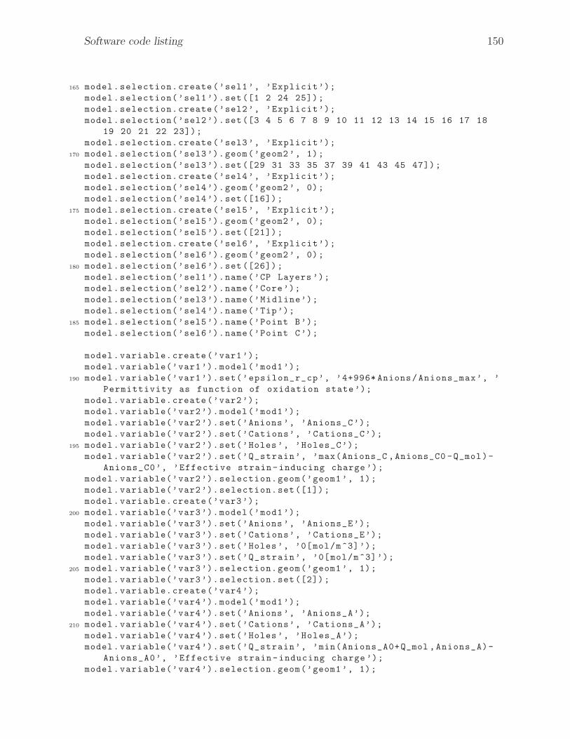
Software code listing 150
165 model.selection.create(’sel1’, ’Explicit’);
model.selection(’sel1’).set([1 2 24 25]);
model.selection.create(’sel2’, ’Explicit’);
model.selection(’sel2’).set([3 4 5 6 7 8 9 10 11 12 13 14 15 16 17 18
19 20 21 22 23]);
model.selection.create(’sel3’, ’Explicit’);
170 model.selection(’sel3’).geom(’geom2’, 1);
model.selection(’sel3’).set([29 31 33 35 37 39 41 43 45 47]);
model.selection.create(’sel4’, ’Explicit’);
model.selection(’sel4’).geom(’geom2’, 0);
model.selection(’sel4’).set([16]);
175 model.selection.create(’sel5’, ’Explicit’);
model.selection(’sel5’).geom(’geom2’, 0);
model.selection(’sel5’).set([21]);
model.selection.create(’sel6’, ’Explicit’);
model.selection(’sel6’).geom(’geom2’, 0);
180 model.selection(’sel6’).set([26]);
model.selection(’sel1’).name(’CP Layers ’);
model.selection(’sel2’).name(’Core’);
model.selection(’sel3’).name(’Midline’);
model.selection(’sel4’).name(’Tip’);
185 model.selection(’sel5’).name(’Point B’);
model.selection(’sel6’).name(’Point C’);
model.variable.create(’var1’);
model.variable(’var1’).model(’mod1’);
190 model.variable(’var1’).set(’epsilon_r_cp’, ’4+996* Anions/Anions_max’, ’
Permittivity as function of oxidation state’);
model.variable.create(’var2’);
model.variable(’var2’).model(’mod1’);
model.variable(’var2’).set(’Anions ’, ’Anions_C’);
model.variable(’var2’).set(’Cations’, ’Cations_C’);
195 model.variable(’var2’).set(’Holes’, ’Holes_C’);
model.variable(’var2’).set(’Q_strain’, ’max(Anions_C ,Anions_C0 -Q_mol)-
Anions_C0’, ’Effective strain-inducing charge ’);
model.variable(’var2’).selection.geom(’geom1’, 1);
model.variable(’var2’).selection.set([1]);
model.variable.create(’var3’);
200 model.variable(’var3’).model(’mod1’);
model.variable(’var3’).set(’Anions ’, ’Anions_E’);
model.variable(’var3’).set(’Cations’, ’Cations_E’);
model.variable(’var3’).set(’Holes’, ’0[mol/m^3]’);
model.variable(’var3’).set(’Q_strain’, ’0[mol/m^3]’);
205 model.variable(’var3’).selection.geom(’geom1’, 1);
model.variable(’var3’).selection.set([2]);
model.variable.create(’var4’);
model.variable(’var4’).model(’mod1’);
model.variable(’var4’).set(’Anions ’, ’Anions_A’);
210 model.variable(’var4’).set(’Cations’, ’Cations_A’);
model.variable(’var4’).set(’Holes’, ’Holes_A’);
model.variable(’var4’).set(’Q_strain’, ’min(Anions_A0+Q_mol ,Anions_A)-
Anions_A0’, ’Effective strain-inducing charge ’);
model.variable(’var4’).selection.geom(’geom1’, 1);

Software code listing 151
model.variable(’var4’).selection.set([3]);
215 model.variable.create(’var5’);
model.variable(’var5’).model(’mod1’);
model.variable(’var5’).set(’N_H_AC ’, ’ppb1[mol/m^3]*mu_H*ppb2[V/m]*
F_const’);
model.variable(’var5’).selection.geom(’geom1’, 0);
model.variable(’var5’).selection.set([1]);
220 model.variable.create(’var6’);
model.variable(’var6’).model(’mod1’);
model.variable(’var6’).set(’N_A_EC ’, ’(Anions_E -Anions_C)*Mk’);
model.variable(’var6’).set(’N_C_EC ’, ’(Cations_E -Cations_C)*Mk’);
model.variable(’var6’).set(’N_A_CE ’, ’ -1*N_A_EC ’);
225 model.variable(’var6’).set(’N_C_CE ’, ’ -1*N_C_EC ’);
model.variable(’var6’).selection.geom(’geom1’, 0);
model.variable(’var6’).selection.set([2]);
model.variable.create(’var7’);
model.variable(’var7’).model(’mod1’);
230 model.variable(’var7’).set(’N_A_EA ’, ’(Anions_E -Anions_A)*Mk*step2(
Anions_A/Anions_max)’);
model.variable(’var7’).set(’N_C_EA ’, ’(Cations_E -Cations_A)*Mk*step2(
Cations_A/Cations_max)’);
model.variable(’var7’).set(’N_A_AE ’, ’ -1*N_A_EA ’);
model.variable(’var7’).set(’N_C_AE ’, ’ -1*N_C_EA ’);
model.variable(’var7’).selection.geom(’geom1’, 0);
235 model.variable(’var7’).selection.set([3]);
model.variable.create(’var8’);
model.variable(’var8’).model(’mod1’);
model.variable(’var8’).set(’N_H_CA ’, ’ -1*ppb1[mol/m^3]* mu_H*ppb2[V/m]*
F_const’);
model.variable(’var8’).selection.geom(’geom1’, 0);
240 model.variable(’var8’).selection.set([4]);
model.variable.create(’var9’);
model.variable(’var9’).model(’mod2’);
model.variable(’var9’).set(’external_x’, ’X’, ’Dimensional coupling’);
model.variable(’var9’).set(’Q_strain_2D’, ’mod1.genext1(mod1.Q_strain)[
mol/m^3]’, ’Variable extrusion from 1D’);
245 model.variable(’var9’).set(’rho_charge’, ’Q_strain_2D*F_const*z_A’, ’
Effective charge density’);
model.variable(’var9’).set(’sigma_induced’, ’beta_cp*rho_charge’, ’
Induced electroactive stress ’);
model.variable.create(’var10’);
model.variable(’var10’).model(’mod2’);
model.variable(’var10’).set(’ax’, ’intoptip(x)’);
250 model.variable(’var10’).set(’ay’, ’intoptip(y)’);
model.variable(’var10’).set(’bx’, ’intopb(x)’);
model.variable(’var10’).set(’by’, ’intopb(y)’);
model.variable(’var10’).set(’cx’, ’intopc(x)’);
model.variable(’var10’).set(’cy’, ’intopc(y)’);
255 model.variable(’var10’).set(’L_tri1 ’, ’sqrt((ax -bx)^2+(ay -by)^2)’);
model.variable(’var10’).set(’L_tri2 ’, ’sqrt((bx -cx)^2+(by -cy)^2)’);
model.variable(’var10’).set(’L_tri3 ’, ’sqrt((cx -ax)^2+(cy -ay)^2)’);
model.variable(’var10’).set(’A_tri’, ’0.25* sqrt((L_tri1 ^2+L_tri2 ^2+
L_tri3 ^2)^2 -2*(L_tri1 ^4+L_tri2 ^4+L_tri3 ^4))’);
model.variable(’var10’).set(’Kappa’, ’4*A_tri/( L_tri1*L_tri2*L_tri3)’);

Software code listing 152
260
model.view.create(’view3’, ’geom2’);
model.material.create(’mat1’);
model.material(’mat1’).model(’mod1’);
265 model.material(’mat1’).selection.set([2]);
model.material.create(’mat2’);
model.material(’mat2’).model(’mod1’);
model.material(’mat2’).selection.set([1 3]);
model.material.create(’mat3’);
270 model.material(’mat3’).selection.named(’sel1’);
model.material.create(’mat4’);
model.material(’mat4’).selection.named(’sel2’);
model.physics.create(’chds’, ’DilutedSpecies’, ’geom1’);
275 model.physics(’chds’).selection.set([1]);
model.physics(’chds’).feature.create(’fl2’, ’Fluxes ’, 0);
model.physics(’chds’).feature(’fl2’).selection.set([1]);
model.physics(’chds’).feature.create(’fl1’, ’Fluxes ’, 0);
model.physics(’chds’).feature(’fl1’).selection.set([2]);
280 model.physics.create(’chds2’, ’DilutedSpecies’, ’geom1’);
model.physics(’chds2’).selection.set([2]);
model.physics(’chds2’).feature.create(’fl1’, ’Fluxes ’, 0);
model.physics(’chds2’).feature(’fl1’).selection.set([2]);
model.physics(’chds2’).feature.create(’fl2’, ’Fluxes ’, 0);
285 model.physics(’chds2’).feature(’fl2’).selection.set([3]);
model.physics.create(’chds3’, ’DilutedSpecies’, ’geom1’);
model.physics(’chds3’).selection.set([3]);
model.physics(’chds3’).feature.create(’fl1’, ’Fluxes ’, 0);
model.physics(’chds3’).feature(’fl1’).selection.set([3]);
290 model.physics(’chds3’).feature.create(’fl2’, ’Fluxes ’, 0);
model.physics(’chds3’).feature(’fl2’).selection.set([4]);
model.physics.create(’es’, ’Electrostatics’, ’geom1’);
model.physics(’es’).feature.create(’gnd1’, ’Ground ’, 0);
model.physics(’es’).feature(’gnd1’).selection.set([1]);
295 model.physics(’es’).feature.create(’pot1’, ’ElectricPotential’, 0);
model.physics(’es’).feature(’pot1’).selection.set([4]);
model.physics.create(’solid’, ’SolidMechanics’, ’geom2’);
model.physics(’solid’).feature(’lemm1’).feature.create(’iss1’, ’
InitialStressandStrain ’, 2);
model.physics(’solid’).feature.create(’fix1’, ’Fixed’, 1);
300 model.physics(’solid’).feature(’fix1’).selection.set([3 65]);
model.physics(’solid’).feature.create(’bl1’, ’BodyLoad’, 2);
model.physics(’solid’).feature(’bl1’).selection.all;
model.physics.create(’ale’, ’MovingMesh’, ’geom2’);
model.physics(’ale’).feature.create(’pres1’, ’PrescribedDeformation’,
2);
305 model.physics(’ale’).feature(’pres1’).selection.all;
model.mesh.create(’mesh1’, ’geom1’);
model.mesh(’mesh1’).feature.create(’auto_f1’, ’Edge’);
model.mesh.create(’mesh2’, ’geom2’);
310 model.mesh(’mesh2’).feature.create(’map1’, ’Map’);
Software code listing 153
model.cpl.create(’genext1’, ’GeneralExtrusion’, ’geom1’);
model.cpl(’genext1’).selection.all;
model.cpl.create(’aveop1 ’, ’Average’, ’geom2’);
315 model.cpl(’aveop1 ’).selection.named(’sel3’);
model.cpl.create(’intop1 ’, ’Integration’, ’geom2’);
model.cpl(’intop1 ’).selection.named(’sel4’);
model.cpl.create(’intop2 ’, ’Integration’, ’geom2’);
model.cpl(’intop2 ’).selection.named(’sel5’);
320 model.cpl.create(’intop3 ’, ’Integration’, ’geom2’);
model.cpl(’intop3 ’).selection.named(’sel6’);
model.result.table.create(’tbl1’, ’Table’);
model.result.table.create(’tbl2’, ’Table’);
325
model.probe.create(’pdom1’, ’DomainPoint’);
model.probe(’pdom1’).model(’mod1’);
model.probe(’pdom1’).feature.create(’ppb2’, ’PointExpr’);
model.probe(’pdom1’).feature.create(’ppb3’, ’PointExpr’);
330
model.variable(’var1’).name(’Dielectric Properties’);
model.variable(’var2’).name(’Cathode’);
model.variable(’var3’).name(’Electrolyte’);
model.variable(’var4’).name(’Anode’);
335 model.variable(’var5’).name(’Boundary Flux: B1’);
model.variable(’var6’).name(’Boundary Flux: B2’);
model.variable(’var7’).name(’Boundary Flux: B3’);
model.variable(’var8’).name(’Boundary Flux: B4’);
model.variable(’var9’).name(’Electroactive Response’);
340 model.variable(’var10’).name(’Curvature Method ’);
model.view(’view1’).axis.set(’xmin’, ’ -10.5’);
model.view(’view1’).axis.set(’xmax’, ’220.5’);
model.view(’view2’).name(’Default’);
345 model.view(’view2’).axis.set(’xmin’, ’ -12266.052734375’);
model.view(’view2’).axis.set(’xmax’, ’12475.3671875’);
model.view(’view2’).axis.set(’ymin’, ’ -750.015380859375’);
model.view(’view2’).axis.set(’ymax’, ’15750.0009765625’);
model.view(’view3’).name(’Fixed Aspect Ratio’);
350 model.view(’view3’).set(’locked ’, true);
model.view(’view3’).axis.set(’xmin’, ’ -16e3’);
model.view(’view3’).axis.set(’xmax’, ’1e3’);
model.view(’view3’).axis.set(’ymin’, ’-1e3’);
model.view(’view3’).axis.set(’ymax’, ’16e3’);
355
model.material(’mat1’).name(’Electrolyte’);
model.material(’mat1’).propertyGroup(’def’).set(’relpermittivity’, {’
epsilon_r_solvent’ ’0’ ’0’ ’0’ ’epsilon_r_solvent’ ’0’ ’0’ ’0’ ’
epsilon_r_solvent’});
model.material(’mat2’).name(’Conductive Polymer’);
model.material(’mat2’).propertyGroup(’def’).set(’relpermittivity’, {’
epsilon_r_cp’ ’0’ ’0’ ’0’ ’epsilon_r_cp’ ’0’ ’0’ ’0’ ’epsilon_r_cp’
});
360 model.material(’mat3’).name(’Conductive Polymer’);

Software code listing 154
model.material(’mat3’).propertyGroup(’def’).set(’youngsmodulus’, ’E_cp’
);
model.material(’mat3’).propertyGroup(’def’).set(’poissonsratio’, ’nu_cp
’);
model.material(’mat3’).propertyGroup(’def’).set(’density’, ’rho_cp ’);
model.material(’mat4’).name(’Porous Membrane Core’);
365 model.material(’mat4’).propertyGroup(’def’).set(’youngsmodulus’, ’
E_core ’);
model.material(’mat4’).propertyGroup(’def’).set(’poissonsratio’, ’
nu_core’);
model.material(’mat4’).propertyGroup(’def’).set(’density’, ’rho_core’);
model.physics(’chds’).name(’Transport in Cathode’);
370 model.physics(’chds’).field(’concentration’).component({’Holes_C’ ’
Anions_C’ ’Cations_C’});
model.physics(’chds’).prop(’Migration’).set(’Migration’, ’1’);
model.physics(’chds’).prop(’Convection’).set(’Convection’, ’0’);
model.physics(’chds’).feature(’cdm1’).set(’V_src’, ’root.mod1.V’);
model.physics(’chds’).feature(’cdm1’).set(’D_0’, {’D_H’; ’0’; ’0’; ’0’;
’D_H’; ’0’; ’0’; ’0’; ’D_H’});
375 model.physics(’chds’).feature(’cdm1’).set(’D_1’, {’D_A’; ’0’; ’0’; ’0’;
’D_A’; ’0’; ’0’; ’0’; ’D_A’});
model.physics(’chds’).feature(’cdm1’).set(’D_2’, {’D_C’; ’0’; ’0’; ’0’;
’D_C’; ’0’; ’0’; ’0’; ’D_C’});
model.physics(’chds’).feature(’cdm1’).set(’z’, {’z_H’; ’z_A’; ’z_C’});
model.physics(’chds’).feature(’cdm1’).set(’um’, {’mu_H’; ’mu_A’; ’mu_C’
});
model.physics(’chds’).feature(’cdm1’).set(’minput_concentration_src ’, ’
root.mod1.Cations_C’);
380 model.physics(’chds’).feature(’init1’).set(’Holes_C’, ’Holes_C0’);
model.physics(’chds’).feature(’init1’).set(’Anions_C’, ’Anions_C0’);
model.physics(’chds’).feature(’init1’).set(’Cations_C’, ’Cations_C0’);
model.physics(’chds’).feature(’fl2’).set(’species’, {’1’; ’1’; ’1’});
model.physics(’chds’).feature(’fl2’).set(’N0’, {’N_H_AC ’; ’0’; ’0’});
385 model.physics(’chds’).feature(’fl2’).name(’Flux: Left Boundary’);
model.physics(’chds’).feature(’fl1’).set(’species’, {’1’; ’1’; ’1’});
model.physics(’chds’).feature(’fl1’).set(’N0’, {’0’; ’N_A_EC ’; ’N_C_EC ’
});
model.physics(’chds’).feature(’fl1’).name(’Flux: Right Boundary’);
model.physics(’chds2’).name(’Transport in Core’);
390 model.physics(’chds2’).field(’concentration’).component({’Anions_E’ ’
Cations_E’});
model.physics(’chds2’).prop(’Migration’).set(’Migration’, ’1’);
model.physics(’chds2’).prop(’Convection’).set(’Convection’, ’0’);
model.physics(’chds2’).feature(’cdm1’).set(’V_src’, ’root.mod1.V’);
model.physics(’chds2’).feature(’cdm1’).set(’D_0’, {’D_A_E’; ’0’; ’0’; ’
0’; ’D_A_E’; ’0’; ’0’; ’0’; ’D_A_E’});
395 model.physics(’chds2’).feature(’cdm1’).set(’D_1’, {’D_C_E’; ’0’; ’0’; ’
0’; ’D_C_E’; ’0’; ’0’; ’0’; ’D_C_E’});
model.physics(’chds2’).feature(’cdm1’).set(’z’, {’z_A’; ’z_C’});
model.physics(’chds2’).feature(’cdm1’).set(’um’, {’mu_A_E*step1(
Anions_E/Anions_E_max)’; ’mu_C_E*step1(Anions_E/Anions_E_max)’});
model.physics(’chds2’).feature(’init1’).set(’Anions_E’, ’Anions_E0’);
model.physics(’chds2’).feature(’init1’).set(’Cations_E’, ’Cations_E0’);

Software code listing 155
400 model.physics(’chds2’).feature(’fl1’).set(’species’, {’1’; ’1’});
model.physics(’chds2’).feature(’fl1’).set(’N0’, {’N_A_CE ’; ’N_C_CE ’});
model.physics(’chds2’).feature(’fl1’).name(’Flux: Left Boundary’);
model.physics(’chds2’).feature(’fl2’).set(’species’, {’1’; ’0’});
model.physics(’chds2’).feature(’fl2’).set(’N0’, {’N_A_AE ’; ’0’});
405 model.physics(’chds2’).feature(’fl2’).name(’Flux: Right Boundary’);
model.physics(’chds3’).name(’Transport in Anode’);
model.physics(’chds3’).field(’concentration’).component({’Holes_A’ ’
Anions_A’ ’Cations_A’});
model.physics(’chds3’).prop(’Migration’).set(’Migration’, ’1’);
model.physics(’chds3’).prop(’Convection’).set(’Convection’, ’0’);
410 model.physics(’chds3’).feature(’cdm1’).set(’V_src’, ’root.mod1.V’);
model.physics(’chds3’).feature(’cdm1’).set(’D_0’, {’D_H’; ’0’; ’0’; ’0’
; ’D_H’; ’0’; ’0’; ’0’; ’D_H’});
model.physics(’chds3’).feature(’cdm1’).set(’D_1’, {’D_A’; ’0’; ’0’; ’0’
; ’D_A’; ’0’; ’0’; ’0’; ’D_A’});
model.physics(’chds3’).feature(’cdm1’).set(’D_2’, {’D_C’; ’0’; ’0’; ’0’
; ’D_C’; ’0’; ’0’; ’0’; ’D_C’});
model.physics(’chds3’).feature(’cdm1’).set(’z’, {’z_H’; ’z_A’; ’z_C’});
415 model.physics(’chds3’).feature(’cdm1’).set(’um’, {’mu_H’; ’mu_A*step1(
Anions_A/Anions_max)’; ’mu_C*step1(Cations_A/Cations_max)’});
model.physics(’chds3’).feature(’init1’).set(’Holes_A’, ’Holes_A0’);
model.physics(’chds3’).feature(’init1’).set(’Anions_A’, ’Anions_A0’);
model.physics(’chds3’).feature(’init1’).set(’Cations_A’, ’Cations_A0’);
model.physics(’chds3’).feature(’fl1’).set(’species’, {’1’; ’1’; ’1’});
420 model.physics(’chds3’).feature(’fl1’).set(’N0’, {’0’; ’N_A_EA ’; ’N_C_EA
’});
model.physics(’chds3’).feature(’fl1’).name(’Flux: Left Boundary’);
model.physics(’chds3’).feature(’fl2’).set(’species’, {’1’; ’1’; ’1’});
model.physics(’chds3’).feature(’fl2’).set(’N0’, {’N_H_CA ’; ’0’; ’0’});
model.physics(’chds3’).feature(’fl2’).name(’Flux: Right Bounday’);
425 model.physics(’es’).feature(’pot1’).set(’V0’, ’V_app’);
model.physics(’solid’).prop(’Type2D ’).set(’Type2D ’, ’PlaneStress’);
model.physics(’solid’).prop(’d’).set(’d’, ’b’);
model.physics(’solid’).feature(’lemm1’).set(’AdvMatRes’, ’1’);
model.physics(’solid’).feature(’lemm1’).feature(’iss1’).set(’Sil’, {’
sigma_induced’; ’0’; ’0’; ’0’; ’sigma_induced’; ’0’; ’0’; ’0’; ’
sigma_induced’});
430 model.physics(’solid’).feature(’bl1’).selection.active(false);
model.physics(’solid’).feature(’bl1’).set(’FperVol’, {’ -1*solid.rho*
g_const’; ’0’; ’0’});
model.physics(’solid’).feature(’bl1’).active(false);
model.physics(’ale’).feature(’disp1’).set(’dx’, {’u’; ’v’});
model.physics(’ale’).feature(’pres1’).set(’dx’, {’u’; ’v’});
435
model.mesh(’mesh1’).feature(’size’).set(’hmax’, ’0.25’);
model.mesh(’mesh1’).feature(’size’).set(’hmin’, ’0.0042 ’);
model.mesh(’mesh1’).feature(’size’).set(’hcurve ’, ’0.2’);
model.mesh(’mesh1’).feature(’size’).set(’hgrad’, ’1.1’);
440 model.mesh(’mesh1’).feature(’size’).set(’hauto’, ’1’);
model.mesh(’mesh1’).feature(’size’).set(’hmax’, ’0.25’);
model.mesh(’mesh1’).run;
model.mesh(’mesh2’).feature(’size’).set(’hmax’, ’h_cp/5’);
model.mesh(’mesh2’).feature(’size’).set(’hmin’, ’h_cp/10’);

Software code listing 156
445 model.mesh(’mesh2’).feature(’size’).set(’hcurve ’, ’0.2’);
model.mesh(’mesh2’).feature(’size’).set(’hgrad’, ’1.1’);
model.mesh(’mesh2’).feature(’size’).set(’hauto’, ’1’);
model.mesh(’mesh2’).feature(’size’).set(’hmax’, ’h_cp/5’);
model.mesh(’mesh2’).feature(’size’).set(’hmin’, ’h_cp/10’);
450 model.mesh(’mesh2’).run;
model.cpl(’genext1’).set(’dstmap ’, {’mod2.external_x’});
model.cpl(’genext1’).set(’srcframe’, ’material’);
model.cpl(’genext1’).set(’usesrcmap’, ’on’);
455 model.cpl(’intop1 ’).set(’opname ’, ’intoptip’);
model.cpl(’intop2 ’).set(’opname ’, ’intopb ’);
model.cpl(’intop3 ’).set(’opname ’, ’intopc ’);
model.result.table(’tbl1’).name(’Probe Table 1’);
460 model.result.table(’tbl2’).comments(’Actuator Curvature (Kappa)’);
model.probe(’pdom1’).feature(’ppb1’).set(’expr’, ’Holes_C’);
model.probe(’pdom1’).feature(’ppb1’).set(’table’, ’tbl1’);
model.probe(’pdom1’).feature(’ppb1’).set(’window ’, ’window1’);
465 model.probe(’pdom1’).feature(’ppb2’).set(’expr’, ’es.Ex’);
model.probe(’pdom1’).feature(’ppb2’).set(’unit’, ’V/m’);
model.probe(’pdom1’).feature(’ppb2’).set(’descr’, ’Electric field , x
component’);
model.probe(’pdom1’).feature(’ppb2’).set(’table’, ’tbl1’);
model.probe(’pdom1’).feature(’ppb2’).set(’window ’, ’window1’);
470 model.probe(’pdom1’).feature(’ppb3’).set(’expr’, ’chds.tfluxMag_Holes_C
’);
model.probe(’pdom1’).feature(’ppb3’).set(’unit’, ’mol/(m^2*s)’);
model.probe(’pdom1’).feature(’ppb3’).set(’descr’, ’Total flux magnitude
’);
model.probe(’pdom1’).feature(’ppb3’).set(’table’, ’tbl1’);
model.probe(’pdom1’).feature(’ppb3’).set(’window ’, ’window2’);
475
model.study.create(’std1’);
model.study(’std1’).feature.create(’param’, ’Parametric’);
model.study(’std1’).feature.create(’time’, ’Transient’);
model.study.create(’std2’);
480 model.study(’std2’).feature.create(’stat’, ’Stationary’);
model.sol.create(’sol1’);
model.sol(’sol1’).study(’std1’);
model.sol(’sol1’).attach(’std1’);
485 model.sol.create(’sol2’);
model.sol(’sol2’).study(’std2’);
model.sol(’sol2’).attach(’std2’);
model.sol.create(’sol3’);
model.sol(’sol3’).study(’std1’);
490 model.sol.create(’sol4’);
model.sol(’sol4’).study(’std1’);
model.sol.create(’sol5’);
model.sol(’sol5’).study(’std1’);
model.sol.create(’sol6’);
495 model.sol(’sol6’).study(’std1’);
Software code listing 157
model.sol.create(’sol7’);
model.sol(’sol7’).study(’std1’);
model.sol(’sol1’).feature.create(’st1’, ’StudyStep’);
model.sol(’sol1’).feature.create(’v1’, ’Variables’);
500 model.sol(’sol1’).feature.create(’t1’, ’Time’);
model.sol(’sol1’).feature(’t1’).feature.create(’fc1’, ’FullyCoupled’);
model.sol(’sol1’).feature(’t1’).feature.create(’d1’, ’Direct ’);
model.sol(’sol1’).feature(’t1’).feature.create(’st1’, ’StopCondition’);
model.sol(’sol1’).feature(’t1’).feature.remove(’fcDef’);
505 model.sol(’sol2’).feature.create(’st1’, ’StudyStep’);
model.sol(’sol2’).feature.create(’v1’, ’Variables’);
model.sol(’sol2’).feature.create(’s1’, ’Stationary’);
model.sol(’sol2’).feature(’s1’).feature.create(’fc1’, ’FullyCoupled’);
model.sol(’sol2’).feature(’s1’).feature.create(’pDef’, ’Parametric’);
510 model.sol(’sol2’).feature(’s1’).feature.remove(’fcDef’);
model.sol(’sol3’).feature.create(’su1’, ’StoreSolution’);
model.sol(’sol3’).feature.create(’su2’, ’StoreSolution’);
model.sol(’sol3’).feature.create(’su3’, ’StoreSolution’);
model.sol(’sol3’).feature.create(’su4’, ’StoreSolution’);
515
model.batch.create(’p1’, ’Parametric’);
model.batch(’p1’).feature.create(’so1’, ’Solutionseq’);
model.batch(’p1’).study(’std1’);
520 model.result.dataset.create(’cpt1’, ’CutPoint1D’);
model.result.dataset.remove(’dset7’);
model.result.dataset.remove(’dset8’);
model.result.dataset.remove(’dset9’);
model.result.dataset.remove(’dset10 ’);
525 model.result.dataset.remove(’dset11 ’);
model.result.dataset.remove(’dset12 ’);
model.result.dataset.remove(’dset13 ’);
model.result.dataset.remove(’dset14 ’);
model.result.dataset.remove(’dset15 ’);
530 model.result.dataset.remove(’dset16 ’);
model.result.dataset.remove(’dset17 ’);
model.result.dataset.remove(’dset18 ’);
model.result.dataset.remove(’dset19 ’);
model.result.dataset.remove(’dset20 ’);
535 model.result.dataset.remove(’dset21 ’);
model.result.dataset.remove(’dset22 ’);
model.result.dataset(’dset2’).set(’probetag’, ’pdom1’);
model.result.dataset(’cpt1’).set(’probetag’, ’pdom1’);
model.result.create(’pg11’, ’PlotGroup1D’);
540 model.result(’pg11’).set(’probetag’, ’none’);
model.result(’pg11’).feature.create(’lngr1’, ’LineGraph’);
model.result(’pg11’).feature(’lngr1’).selection.all;
model.result(’pg11’).feature.create(’lngr3’, ’LineGraph’);
model.result(’pg11’).feature(’lngr3’).selection.set([1]);
545 model.result(’pg11’).feature.create(’lngr2’, ’LineGraph’);
model.result(’pg11’).feature(’lngr2’).selection.set([3]);
model.result.create(’pg10’, ’PlotGroup1D’);
model.result(’pg10’).set(’probetag’, ’none’);
model.result(’pg10’).feature.create(’lngr1’, ’LineGraph’);

Software code listing 158
550 model.result(’pg10’).feature(’lngr1’).selection.all;
model.result(’pg10’).feature.create(’lngr2’, ’LineGraph’);
model.result(’pg10’).feature(’lngr2’).selection.set([3]);
model.result.create(’pg1’, ’PlotGroup1D’);
model.result(’pg1’).set(’probetag’, ’none’);
555 model.result(’pg1’).feature.create(’lngr1’, ’LineGraph’);
model.result(’pg1’).feature.create(’lngr2’, ’LineGraph’);
model.result.create(’pg2’, ’PlotGroup1D’);
model.result(’pg2’).set(’probetag’, ’none’);
model.result(’pg2’).feature.create(’lngr1’, ’LineGraph’);
560 model.result(’pg2’).feature(’lngr1’).selection.all;
model.result.create(’pg3’, ’PlotGroup1D’);
model.result(’pg3’).set(’probetag’, ’none’);
model.result(’pg3’).feature.create(’lngr1’, ’LineGraph’);
model.result(’pg3’).feature(’lngr1’).selection.all;
565 model.result.create(’pg5’, ’PlotGroup1D’);
model.result(’pg5’).set(’probetag’, ’none’);
model.result(’pg5’).feature.create(’lngr1’, ’LineGraph’);
model.result(’pg5’).feature(’lngr1’).selection.all;
model.result.create(’pg4’, ’PlotGroup1D’);
570 model.result(’pg4’).set(’probetag’, ’window1_default’);
model.result(’pg4’).feature.create(’tblp1’, ’Table’);
model.result(’pg4’).feature(’tblp1’).set(’probetag’, ’ppb2’);
model.result.create(’pg6’, ’PlotGroup1D’);
model.result(’pg6’).set(’probetag’, ’none’);
575 model.result(’pg6’).feature.create(’ptgr1’, ’PointGraph’);
model.result(’pg6’).feature(’ptgr1’).selection.set([1]);
model.result(’pg6’).feature.create(’ptgr2’, ’PointGraph’);
model.result(’pg6’).feature(’ptgr2’).selection.set([3]);
model.result(’pg6’).feature.create(’ptgr3’, ’PointGraph’);
580 model.result(’pg6’).feature(’ptgr3’).selection.set([3]);
model.result.create(’pg7’, ’PlotGroup1D’);
model.result(’pg7’).set(’probetag’, ’window1’);
model.result(’pg7’).feature.create(’tblp1’, ’Table’);
model.result(’pg7’).feature(’tblp1’).set(’probetag’, ’ppb2’);
585 model.result.create(’pg8’, ’PlotGroup1D’);
model.result(’pg8’).set(’probetag’, ’window2_default’);
model.result(’pg8’).feature.create(’tblp1’, ’Table’);
model.result(’pg8’).feature(’tblp1’).set(’probetag’, ’ppb3’);
model.result.create(’pg9’, ’PlotGroup1D’);
590 model.result(’pg9’).set(’probetag’, ’none’);
model.result(’pg9’).feature.create(’lngr1’, ’LineGraph’);
model.result(’pg9’).feature(’lngr1’).selection.all;
model.result.create(’pg12’, ’PlotGroup2D’);
model.result(’pg12’).feature.create(’mesh1’, ’Mesh’);
595 model.result.create(’pg13’, ’PlotGroup1D’);
model.result(’pg13’).set(’probetag’, ’window1’);
model.result(’pg13’).feature.create(’tblp1’, ’Table’);
model.result(’pg13’).feature(’tblp1’).set(’probetag’, ’ppb2’);
model.result.create(’pg14’, ’PlotGroup1D’);
600 model.result(’pg14’).set(’probetag’, ’window2’);
model.result(’pg14’).feature.create(’tblp1’, ’Table’);
model.result(’pg14’).feature(’tblp1’).set(’probetag’, ’ppb3’);
model.result.create(’pg15’, ’PlotGroup2D’);
Software code listing 159
model.result(’pg4’).feature(’tblp1’).set(’probetag’, ’ppb2’);
605 model.result(’pg7’).feature(’tblp1’).set(’probetag’, ’ppb2’);
model.result(’pg8’).feature(’tblp1’).set(’probetag’, ’ppb3’);
model.result(’pg13’).feature(’tblp1’).set(’probetag’, ’ppb2’);
model.result(’pg14’).feature(’tblp1’).set(’probetag’, ’ppb3’);
model.result.numerical.create(’pev1’, ’EvalPoint’);
610 model.result.numerical(’pev1’).set(’probetag’, ’ppb1’);
model.result.numerical.create(’pev2’, ’EvalPoint’);
model.result.numerical(’pev2’).set(’probetag’, ’ppb2’);
model.result.numerical.create(’pev3’, ’EvalPoint’);
model.result.numerical(’pev3’).set(’probetag’, ’ppb3’);
615 model.result.numerical.create(’gev1’, ’EvalGlobal’);
model.result.numerical(’gev1’).set(’probetag’, ’none’);
model.probe(’pdom1’).genResult([]);
620 model.study(’std1’).name(’Transport’);
model.study(’std1’).feature(’param’).set(’pname’, {’param_V’});
model.study(’std1’).feature(’param’).set(’plist’, ’range(1,1,4)’);
model.study(’std1’).feature(’time’).set(’activate’, {’chds’ ’on’ ’chds2
’ ’on’ ’chds3’ ’on’ ’es’ ’on’ ’solid’ ’off’ ’ale’ ’off’});
model.study(’std1’).feature(’time’).set(’tlist’, ’range(t0 ,dt ,tf)’);
625 model.study(’std1’).feature(’time’).set(’rtol’, ’0.001’);
model.study(’std1’).feature(’time’).set(’rtolactive’, true);
model.study(’std2’).name(’Mechanics’);
model.study(’std2’).feature(’stat’).set(’activate’, {’chds’ ’off’ ’
chds2’ ’off’ ’chds3’ ’off’ ’es’ ’off’ ’solid’ ’on’ ’ale’ ’on’});
model.study(’std2’).feature(’stat’).set(’usesol ’, ’on’);
630 model.study(’std2’).feature(’stat’).set(’notsolmethod’, ’sol’);
model.study(’std2’).feature(’stat’).set(’notstudy’, ’std1’);
model.study(’std2’).feature(’stat’).set(’useparam’, ’on’);
model.study(’std2’).feature(’stat’).set(’pname’, {’param_V’});
model.study(’std2’).feature(’stat’).set(’plist’, ’range (1,1,4)’);
635
model.sol(’sol1’).feature(’st1’).name(’Compile Equations: Time
Dependent’);
model.sol(’sol1’).feature(’st1’).set(’studystep’, ’time’);
model.sol(’sol1’).feature(’v1’).set(’control’, ’time’);
model.sol(’sol1’).feature(’v1’).feature(’mod2_u ’).set(’solvefor’, false
);
640 model.sol(’sol1’).feature(’v1’).feature(’mod2_wZ’).set(’solvefor’,
false);
model.sol(’sol1’).feature(’t1’).set(’control’, ’time’);
model.sol(’sol1’).feature(’t1’).set(’tlist’, ’range(t0 ,dt ,tf)’);
model.sol(’sol1’).feature(’t1’).set(’rtol’, ’0.001’);
model.sol(’sol1’).feature(’t1’).set(’atolmethod’, {’mod1_V ’ ’global ’ ’
mod1_Holes_A’ ’global ’ ’mod1_Holes_C’ ’global ’ ’mod1_Cations_A’ ’
global ’ ’mod1_Anions_A’ ’global ’ ’mod1_Cations_E’ ’global ’ ’
mod1_Anions_E’ ’global ’ ’mod1_Cations_C’ ’global ’ ’mod1_Anions_C’ ’
global ’ ’mod2_u ’ ’global ’ ’mod2_wZ’ ’global ’});

Software code listing 160
645 model.sol(’sol1’).feature(’t1’).set(’atol’, {’mod1_V ’ ’1e-3’ ’
mod1_Holes_A’ ’1e-3’ ’mod1_Holes_C’ ’1e-3’ ’mod1_Cations_A’ ’1e-3’ ’
mod1_Anions_A’ ’1e-3’ ’mod1_Cations_E’ ’1e-3’ ’mod1_Anions_E’ ’1e-3’
’mod1_Cations_C’ ’1e-3’ ’mod1_Anions_C’ ’1e-3’ ’mod2_u ’ ’1e-3’ ’
mod2_wZ’ ’1e-3’});
model.sol(’sol1’).feature(’t1’).set(’atoludot’, {’mod1_V ’ ’1e-3’ ’
mod1_Holes_A’ ’1e-3’ ’mod1_Holes_C’ ’1e-3’ ’mod1_Cations_A’ ’1e-3’ ’
mod1_Anions_A’ ’1e-3’ ’mod1_Cations_E’ ’1e-3’ ’mod1_Anions_E’ ’1e-3’
’mod1_Cations_C’ ’1e-3’ ’mod1_Anions_C’ ’1e-3’ ’mod2_u ’ ’1e-3’ ’
mod2_wZ’ ’1e-3’});
model.sol(’sol1’).feature(’t1’).set(’atoludotactive’, {’mod1_V ’ ’off’ ’
mod1_Holes_A’ ’off’ ’mod1_Holes_C’ ’off’ ’mod1_Cations_A’ ’off’ ’
mod1_Anions_A’ ’off’ ’mod1_Cations_E’ ’off’ ’mod1_Anions_E’ ’off’ ’
mod1_Cations_C’ ’off’ ’mod1_Anions_C’ ’off’ ’mod2_u ’ ’off’ ’mod2_wZ’
’off’});
model.sol(’sol1’).feature(’t1’).set(’timemethod’, ’genalpha’);
model.sol(’sol1’).feature(’t1’).set(’rhoinf ’, ’0.1’);
650 model.sol(’sol1’).feature(’t1’).set(’predictor’, ’constant’);
model.sol(’sol1’).feature(’t1’).feature(’fc1’).set(’maxiter’, ’5’);
model.sol(’sol1’).feature(’t1’).feature(’fc1’).set(’jtech’, ’once’);
model.sol(’sol1’).feature(’t1’).feature(’st1’).active(false);
model.sol(’sol1’).feature(’t1’).feature(’st1’).set(’stopcond’, ’mod1.
ppb3 -1e-10’);
655 model.sol(’sol2’).feature(’st1’).name(’Compile Equations: Stationary’);
model.sol(’sol2’).feature(’st1’).set(’study’, ’std2’);
model.sol(’sol2’).feature(’st1’).set(’studystep’, ’stat’);
model.sol(’sol2’).feature(’v1’).set(’control’, ’stat’);
model.sol(’sol2’).feature(’v1’).set(’notsolmethod’, ’sol’);
660 model.sol(’sol2’).feature(’v1’).set(’notsol ’, ’sol1’);
model.sol(’sol2’).feature(’v1’).feature(’mod1_V ’).set(’solvefor’, false
);
model.sol(’sol2’).feature(’v1’).feature(’mod1_Holes_A’).set(’solvefor’,
false);
model.sol(’sol2’).feature(’v1’).feature(’mod1_Holes_C’).set(’solvefor’,
false);
model.sol(’sol2’).feature(’v1’).feature(’mod1_Cations_A’).set(’solvefor
’, false);
665 model.sol(’sol2’).feature(’v1’).feature(’mod1_Anions_A’).set(’solvefor’
, false);
model.sol(’sol2’).feature(’v1’).feature(’mod1_Cations_E’).set(’solvefor
’, false);
model.sol(’sol2’).feature(’v1’).feature(’mod1_Anions_E’).set(’solvefor’
, false);
model.sol(’sol2’).feature(’v1’).feature(’mod1_Cations_C’).set(’solvefor
’, false);
model.sol(’sol2’).feature(’v1’).feature(’mod1_Anions_C’).set(’solvefor’
, false);
670 model.sol(’sol2’).feature(’s1’).set(’control’, ’stat’);
model.sol(’sol2’).feature(’s1’).set(’stol’, ’0.00010’);
model.sol(’sol2’).feature(’s1’).set(’nonlin ’, ’on’);
model.sol(’sol2’).feature(’s1’).feature(’fc1’).set(’dtech’, ’const’);
model.sol(’sol2’).feature(’s1’).feature(’fc1’).set(’maxiter’, ’50’);
675 model.sol(’sol2’).feature(’s1’).feature(’pDef’).set(’control’, ’stat’);

Software code listing 161
model.sol(’sol2’).feature(’s1’).feature(’pDef’).set(’pname’, {’param_V’
});
model.sol(’sol2’).feature(’s1’).feature(’pDef’).set(’plist’, ’range
(1,1,4)’);
model.sol(’sol3’).name(’Parametric 3’);
model.sol(’sol3’).feature(’su1’).name(’Store Solution 4’);
680 model.sol(’sol3’).feature(’su1’).set(’sol’, ’sol4’);
model.sol(’sol3’).feature(’su2’).name(’Store Solution 5’);
model.sol(’sol3’).feature(’su2’).set(’sol’, ’sol5’);
model.sol(’sol3’).feature(’su3’).name(’Store Solution 6’);
model.sol(’sol3’).feature(’su3’).set(’sol’, ’sol6’);
685 model.sol(’sol3’).feature(’su4’).name(’Store Solution 7’);
model.sol(’sol3’).feature(’su4’).set(’sol’, ’sol7’);
model.sol(’sol4’).name(’Store Solution 4’);
model.sol(’sol5’).name(’Store Solution 5’);
model.sol(’sol6’).name(’Store Solution 6’);
690 model.sol(’sol7’).name(’Store Solution 7’);
model.batch(’p1’).set(’control’, ’param’);
model.batch(’p1’).set(’pname’, {’param_V’});
model.batch(’p1’).set(’plist’, ’range(1,1,4)’);
695 model.batch(’p1’).set(’err’, true);
model.batch(’p1’).feature(’so1’).set(’seq’, ’sol1’);
model.batch(’p1’).feature(’so1’).set(’store’, ’on’);
model.batch(’p1’).feature(’so1’).set(’psol’, ’sol3’);
model.batch(’p1’).feature(’so1’).set(’param’, {’"param_V","1"’ ’"
param_V","2"’ ’"param_V","3"’ ’"param_V","4"’});
700 model.batch(’p1’).attach(’std1’);
model.batch(’p1’).run;
model.result.dataset(’dset1’).set(’frametype’, ’material’);
model.result.dataset(’dset2’).name(’Probe Solution 2’);
705 model.result.dataset(’dset2’).set(’solution’, ’sol2’);
model.result.dataset(’dset2’).set(’geom’, ’geom1’);
model.result.dataset(’dset2’).set(’frametype’, ’material’);
model.result.dataset(’cpt1’).set(’data’, ’dset2’);
model.result.dataset.remove(’dset7’);
710 model.result(’pg11’).name(’Effective Charge ’);
model.result(’pg11’).set(’title’, ’Line Graph: Effective strain-
inducing charge (mol/m<sup >3</sup >) Line Graph: -1*Q_mol (mol/m<sup
>3</sup >) Line Graph: Effective hole concentration (mol/m<sup >3</sup
>) ’);
model.result(’pg11’).set(’xlabel ’, [’x-coordinate (’ native2unicode(
hex2dec(’00b5’), ’Cp1252 ’) ’m)’]);
model.result(’pg11’).set(’titleactive’, false);
model.result(’pg11’).set(’xlabelactive’, false);
715 model.result(’pg11’).feature(’lngr1’).name(’Actual ’);
model.result(’pg11’).feature(’lngr1’).set(’expr’, ’Q_strain’);
model.result(’pg11’).feature(’lngr1’).set(’descr’, ’Effective strain -
inducing charge ’);
model.result(’pg11’).feature(’lngr1’).set(’xdata’, ’expr’);
model.result(’pg11’).feature(’lngr1’).set(’xdataexpr’, ’x’);
720 model.result(’pg11’).feature(’lngr1’).set(’xdataunit’, [native2unicode(
hex2dec(’00b5’), ’Cp1252 ’) ’m’]);

Software code listing 162
model.result(’pg11’).feature(’lngr1’).set(’xdatadescr’, ’x-coordinate’)
;
model.result(’pg11’).feature(’lngr3’).name(’Cathode’);
model.result(’pg11’).feature(’lngr3’).set(’expr’, ’ -1*Q_mol’);
model.result(’pg11’).feature(’lngr3’).set(’descr’, ’ -1*Q_mol’);
725 model.result(’pg11’).feature(’lngr3’).set(’xdata’, ’expr’);
model.result(’pg11’).feature(’lngr3’).set(’xdataexpr’, ’x’);
model.result(’pg11’).feature(’lngr3’).set(’xdataunit’, [native2unicode(
hex2dec(’00b5’), ’Cp1252 ’) ’m’]);
model.result(’pg11’).feature(’lngr3’).set(’xdatadescr’, ’x-coordinate’)
;
model.result(’pg11’).feature(’lngr3’).set(’linestyle’, ’dashed ’);
730 model.result(’pg11’).feature(’lngr3’).set(’linecolor’, ’gray’);
model.result(’pg11’).feature(’lngr2’).name(’Anode’);
model.result(’pg11’).feature(’lngr2’).set(’expr’, ’Q_mol’);
model.result(’pg11’).feature(’lngr2’).set(’descr’, ’Effective hole
concentration’);
model.result(’pg11’).feature(’lngr2’).set(’xdata’, ’expr’);
735 model.result(’pg11’).feature(’lngr2’).set(’xdataexpr’, ’x’);
model.result(’pg11’).feature(’lngr2’).set(’xdataunit’, [native2unicode(
hex2dec(’00b5’), ’Cp1252 ’) ’m’]);
model.result(’pg11’).feature(’lngr2’).set(’xdatadescr’, ’x-coordinate’)
;
model.result(’pg11’).feature(’lngr2’).set(’linestyle’, ’dotted ’);
model.result(’pg11’).feature(’lngr2’).set(’linecolor’, ’gray’);
740 model.result(’pg10’).name(’Anions ’);
model.result(’pg10’).set(’t’, ’range(t0 ,1,tf)’);
model.result(’pg10’).set(’title’, ’Line Graph: (mol/m<sup >3</sup >)
Line Graph: Solubility limit (mol/m<sup >3</sup >) ’);
model.result(’pg10’).set(’xlabel ’, [’x-coordinate (’ native2unicode(
hex2dec(’00b5’), ’Cp1252 ’) ’m)’]);
model.result(’pg10’).set(’titleactive’, false);
745 model.result(’pg10’).set(’xlabelactive’, false);
model.result(’pg10’).feature(’lngr1’).set(’expr’, ’Anions ’);
model.result(’pg10’).feature(’lngr1’).set(’descr’, ’’);
model.result(’pg10’).feature(’lngr1’).set(’xdata’, ’expr’);
model.result(’pg10’).feature(’lngr1’).set(’xdataexpr’, ’x’);
750 model.result(’pg10’).feature(’lngr1’).set(’xdataunit’, [native2unicode(
hex2dec(’00b5’), ’Cp1252 ’) ’m’]);
model.result(’pg10’).feature(’lngr1’).set(’xdatadescr’, ’x-coordinate’)
;
model.result(’pg10’).feature(’lngr2’).set(’expr’, ’Anions_max’);
model.result(’pg10’).feature(’lngr2’).set(’descr’, ’Solubility limit’);
model.result(’pg10’).feature(’lngr2’).set(’xdata’, ’expr’);
755 model.result(’pg10’).feature(’lngr2’).set(’xdataexpr’, ’x’);
model.result(’pg10’).feature(’lngr2’).set(’xdataunit’, [native2unicode(
hex2dec(’00b5’), ’Cp1252 ’) ’m’]);
model.result(’pg10’).feature(’lngr2’).set(’xdatadescr’, ’x-coordinate’)
;
model.result(’pg10’).feature(’lngr2’).set(’linestyle’, ’dashed ’);
model.result(’pg10’).feature(’lngr2’).set(’linecolor’, ’gray’);
760 model.result(’pg1’).name(’Anions (Anode only)’);
model.result(’pg1’).set(’data’, ’dset6’);

Software code listing 163
model.result(’pg1’).set(’title’, ’Line Graph: (mol/m<sup >3</sup >) Line
Graph: Solubility limit (mol/m<sup >3</sup >) ’);
model.result(’pg1’).set(’xlabel ’, [’x-coordinate (’ native2unicode(
hex2dec(’00b5’), ’Cp1252 ’) ’m)’]);
model.result(’pg1’).set(’axislimits’, ’on’);
765 model.result(’pg1’).set(’xmin’, ’161.75685119628906’);
model.result(’pg1’).set(’xmax’, ’162.70555114746094’);
model.result(’pg1’).set(’ymin’, ’249.09909057617188’);
model.result(’pg1’).set(’ymax’, ’252.13963317871094’);
model.result(’pg1’).set(’windowtitle’, ’Graphics’);
770 model.result(’pg1’).set(’titleactive’, false);
model.result(’pg1’).set(’xlabelactive’, false);
model.result(’pg1’).feature(’lngr1’).set(’expr’, ’Anions ’);
model.result(’pg1’).feature(’lngr1’).set(’descr’, ’’);
model.result(’pg1’).feature(’lngr1’).set(’xdata’, ’expr’);
775 model.result(’pg1’).feature(’lngr1’).set(’xdataexpr’, ’x’);
model.result(’pg1’).feature(’lngr1’).set(’xdataunit’, [native2unicode(
hex2dec(’00b5’), ’Cp1252 ’) ’m’]);
model.result(’pg1’).feature(’lngr1’).set(’xdatadescr’, ’x-coordinate’);
model.result(’pg1’).feature(’lngr2’).set(’expr’, ’Anions_max’);
model.result(’pg1’).feature(’lngr2’).set(’descr’, ’Solubility limit’);
780 model.result(’pg1’).feature(’lngr2’).set(’xdata’, ’expr’);
model.result(’pg1’).feature(’lngr2’).set(’xdataexpr’, ’x’);
model.result(’pg1’).feature(’lngr2’).set(’xdataunit’, [native2unicode(
hex2dec(’00b5’), ’Cp1252 ’) ’m’]);
model.result(’pg1’).feature(’lngr2’).set(’xdatadescr’, ’x-coordinate’);
model.result(’pg1’).feature(’lngr2’).set(’linestyle’, ’dotted ’);
785 model.result(’pg1’).feature(’lngr2’).set(’linecolor’, ’red’);
model.result(’pg2’).name(’Cations’);
model.result(’pg2’).set(’title’, ’Line Graph: Cations (mol/m<sup >3</sup
>) ’);
model.result(’pg2’).set(’xlabel ’, [’x-coordinate (’ native2unicode(
hex2dec(’00b5’), ’Cp1252 ’) ’m)’]);
model.result(’pg2’).set(’ylabel ’, ’Cations (mol/m<sup >3</sup >)’);
790 model.result(’pg2’).set(’windowtitle’, ’Graphics’);
model.result(’pg2’).set(’titleactive’, false);
model.result(’pg2’).set(’xlabelactive’, false);
model.result(’pg2’).set(’ylabelactive’, false);
model.result(’pg2’).feature(’lngr1’).set(’expr’, ’Cations’);
795 model.result(’pg2’).feature(’lngr1’).set(’descr’, ’Cations’);
model.result(’pg2’).feature(’lngr1’).set(’xdata’, ’expr’);
model.result(’pg2’).feature(’lngr1’).set(’xdataexpr’, ’x’);
model.result(’pg2’).feature(’lngr1’).set(’xdataunit’, [native2unicode(
hex2dec(’00b5’), ’Cp1252 ’) ’m’]);
model.result(’pg2’).feature(’lngr1’).set(’xdatadescr’, ’x-coordinate’);
800 model.result(’pg3’).name(’Holes’);
model.result(’pg3’).set(’title’, ’Line Graph: Holes (mol/m<sup >3</sup >)
’);
model.result(’pg3’).set(’xlabel ’, [’x-coordinate (’ native2unicode(
hex2dec(’00b5’), ’Cp1252 ’) ’m)’]);
model.result(’pg3’).set(’ylabel ’, ’Holes (mol/m<sup >3</sup >)’);
model.result(’pg3’).set(’windowtitle’, ’Graphics’);
805 model.result(’pg3’).set(’titleactive’, false);
model.result(’pg3’).set(’xlabelactive’, false);

Software code listing 164
model.result(’pg3’).set(’ylabelactive’, false);
model.result(’pg3’).feature(’lngr1’).set(’expr’, ’Holes ’);
model.result(’pg3’).feature(’lngr1’).set(’descr’, ’Holes’);
810 model.result(’pg3’).feature(’lngr1’).set(’xdata’, ’expr’);
model.result(’pg3’).feature(’lngr1’).set(’xdataexpr’, ’x’);
model.result(’pg3’).feature(’lngr1’).set(’xdataunit’, [native2unicode(
hex2dec(’00b5’), ’Cp1252 ’) ’m’]);
model.result(’pg3’).feature(’lngr1’).set(’xdatadescr’, ’x-coordinate’);
model.result(’pg5’).name(’Potential’);
815 model.result(’pg5’).set(’title’, ’Line Graph: Electric potential (V) ’)
;
model.result(’pg5’).set(’xlabel ’, [’x-coordinate (’ native2unicode(
hex2dec(’00b5’), ’Cp1252 ’) ’m)’]);
model.result(’pg5’).set(’ylabel ’, ’Electric potential (V)’);
model.result(’pg5’).set(’windowtitle’, ’Graphics’);
model.result(’pg5’).set(’titleactive’, false);
820 model.result(’pg5’).set(’xlabelactive’, false);
model.result(’pg5’).set(’ylabelactive’, false);
model.result(’pg5’).feature(’lngr1’).set(’expr’, ’V’);
model.result(’pg5’).feature(’lngr1’).set(’unit’, ’V’);
model.result(’pg5’).feature(’lngr1’).set(’descr’, ’Electric potential’)
;
825 model.result(’pg5’).feature(’lngr1’).set(’xdata’, ’expr’);
model.result(’pg5’).feature(’lngr1’).set(’xdataexpr’, ’x’);
model.result(’pg5’).feature(’lngr1’).set(’xdataunit’, [native2unicode(
hex2dec(’00b5’), ’Cp1252 ’) ’m’]);
model.result(’pg5’).feature(’lngr1’).set(’xdatadescr’, ’x-coordinate’);
model.result(’pg4’).active(false);
830 model.result(’pg4’).name(’Probe 1D Plot Group 4’);
model.result(’pg4’).set(’windowtitle’, ’Probe Plot 1’);
model.result(’pg4’).feature(’tblp1’).name(’Probe Table Plot 1’);
model.result(’pg6’).name(’Flux’);
model.result(’pg6’).set(’title’, ’Point Graph: Normal Holes left (mol/(
m<sup >2</sup >*s)) Point Graph: Normal Anions right interface (mol/(m
<sup >2</sup >*s)) Point Graph: Normal total flux (mol/(m<sup >2</sup >*
s)) ’);
835 model.result(’pg6’).set(’xlabel ’, ’Time’);
model.result(’pg6’).set(’windowtitle’, ’Graphics’);
model.result(’pg6’).set(’titleactive’, false);
model.result(’pg6’).set(’xlabelactive’, false);
model.result(’pg6’).feature(’ptgr1’).set(’expr’, ’chds.ntflux_Holes_C’)
;
840 model.result(’pg6’).feature(’ptgr1’).set(’unit’, ’mol/(m^2*s)’);
model.result(’pg6’).feature(’ptgr1’).set(’descractive’, true);
model.result(’pg6’).feature(’ptgr1’).set(’descr’, ’Normal Holes left’);
model.result(’pg6’).feature(’ptgr2’).set(’expr’, ’chds3.ntflux_Anions_A
’);
model.result(’pg6’).feature(’ptgr2’).set(’unit’, ’mol/(m^2*s)’);
845 model.result(’pg6’).feature(’ptgr2’).set(’descractive’, true);
model.result(’pg6’).feature(’ptgr2’).set(’descr’, ’Normal Anions right
interface’);
model.result(’pg6’).feature(’ptgr3’).set(’expr’, ’chds3.
ntflux_Cations_A’);
model.result(’pg6’).feature(’ptgr3’).set(’unit’, ’mol/(m^2*s)’);

Software code listing 165
model.result(’pg6’).feature(’ptgr3’).set(’descr’, ’Normal total flux’);
850 model.result.create(’pg7’, ’PlotGroup1D’);
model.result(’pg7’).active(false);
model.result(’pg7’).name(’Probe 1D Plot Group 7’);
model.result(’pg7’).set(’data’, ’none’);
model.result(’pg7’).set(’window ’, ’window1’);
855 model.result(’pg7’).set(’windowtitle’, ’Probe Plot 1’);
model.result(’pg7’).feature.create(’tblp1’, ’Table’);
model.result(’pg7’).feature(’tblp1’).name(’Probe Table Plot 1’);
model.result(’pg7’).feature(’tblp1’).set(’plotcolumninput’, ’manual ’);
model.result(’pg8’).active(false);
860 model.result(’pg8’).name(’Probe 1D Plot Group 8’);
model.result(’pg8’).set(’windowtitle’, ’Probe Plot 2’);
model.result(’pg8’).feature(’tblp1’).name(’Probe Table Plot 1’);
model.result(’pg9’).name(’Charge Neutrality’);
model.result(’pg9’).set(’title’, ’Line Graph: Holes+Cations -Anions (mol
/m<sup >3</sup >) ’);
865 model.result(’pg9’).set(’xlabel ’, [’x-coordinate (’ native2unicode(
hex2dec(’00b5’), ’Cp1252 ’) ’m)’]);
model.result(’pg9’).set(’ylabel ’, ’Holes+Cations -Anions (mol/m<sup >3</
sup >)’);
model.result(’pg9’).set(’titleactive’, false);
model.result(’pg9’).set(’xlabelactive’, false);
model.result(’pg9’).set(’ylabelactive’, false);
870 model.result(’pg9’).feature(’lngr1’).set(’expr’, ’Holes+Cations -Anions ’
);
model.result(’pg9’).feature(’lngr1’).set(’descr’, ’Holes+Cations -Anions
’);
model.result(’pg9’).feature(’lngr1’).set(’xdata’, ’expr’);
model.result(’pg9’).feature(’lngr1’).set(’xdataexpr’, ’x’);
model.result(’pg9’).feature(’lngr1’).set(’xdataunit’, [native2unicode(
hex2dec(’00b5’), ’Cp1252 ’) ’m’]);
875 model.result(’pg9’).feature(’lngr1’).set(’xdatadescr’, ’x-coordinate’);
model.result(’pg12’).name(’Deformation’);
model.result(’pg12’).set(’view’, ’view3’);
model.result(’pg12’).set(’title’, ’Mesh: Quality ’);
model.result(’pg12’).set(’edges’, ’off’);
880 model.result(’pg12’).set(’titleactive’, false);
model.result(’pg12’).feature(’mesh1’).set(’meshdomain’, ’line’);
model.result(’pg12’).feature(’mesh1’).set(’elemcolor’, ’black’);
model.result(’pg12’).feature(’mesh1’).set(’wireframecolor’, ’none’);
model.result.create(’pg13’, ’PlotGroup1D’);
885 model.result(’pg13’).name(’Probe 1D Plot Group 13’);
model.result(’pg13’).set(’data’, ’none’);
model.result(’pg13’).set(’title’, ’ ’);
model.result(’pg13’).set(’xlabel ’, ’param_V’);
model.result(’pg13’).set(’window ’, ’window1’);
890 model.result(’pg13’).set(’windowtitle’, ’Probe Plot 1’);
model.result(’pg13’).set(’titleactive’, false);
model.result(’pg13’).set(’xlabelactive’, false);
model.result(’pg13’).feature.create(’tblp1’, ’Table’);
model.result(’pg13’).feature(’tblp1’).name(’Probe Table Plot 1’);
895 model.result(’pg13’).feature(’tblp1’).set(’plotcolumninput’, ’manual ’);
model.result.create(’pg14’, ’PlotGroup1D’);

Software code listing 166
model.result(’pg14’).name(’Probe 1D Plot Group 14’);
model.result(’pg14’).set(’data’, ’none’);
model.result(’pg14’).set(’title’, ’ ’);
900 model.result(’pg14’).set(’xlabel ’, ’param_V’);
model.result(’pg14’).set(’window ’, ’window2’);
model.result(’pg14’).set(’windowtitle’, ’Probe Plot 2’);
model.result(’pg14’).set(’titleactive’, false);
model.result(’pg14’).set(’xlabelactive’, false);
905 model.result(’pg14’).feature.create(’tblp1’, ’Table’);
model.result(’pg14’).feature(’tblp1’).name(’Probe Table Plot 1’);
model.result(’pg14’).feature(’tblp1’).set(’plotcolumninput’, ’manual ’);
model.result(’pg15’).name(’Undeformed’);
model.result(’pg15’).set(’view’, ’view3’);
910 model.result(’pg15’).set(’title’, ’param_V(4)=4 ’);
model.result(’pg15’).set(’titleactive’, false);
model.result.numerical(’gev1’).name(’Actuator Curvature’);
model.result.numerical(’gev1’).set(’data’, ’dset4’);
model.result.numerical(’gev1’).set(’table’, ’tbl2’);
915 model.result.numerical(’gev1’).set(’expr’, ’Kappa’);
model.result.numerical(’gev1’).set(’unit’, ’1/m’);
model.result.numerical(’gev1’).set(’descr’, ’Midplane Curvature’);
model.result.numerical(’pev1’).setResult;
model.result.numerical(’pev2’).appendResult;
920 model.result.numerical(’pev3’).appendResult;
model.result.numerical(’gev1’).setResult;
out = model;
Related Documents