This content has been downloaded from IOPscience. Please scroll down to see the full text. Download details: IP Address: 144.214.79.246 This content was downloaded on 05/06/2014 at 06:21 Please note that terms and conditions apply. Fabrication and testing of an energy-harvesting hydraulic damper View the table of contents for this issue, or go to the journal homepage for more 2013 Smart Mater. Struct. 22 065024 (http://iopscience.iop.org/0964-1726/22/6/065024) Home Search Collections Journals About Contact us My IOPscience

Welcome message from author
This document is posted to help you gain knowledge. Please leave a comment to let me know what you think about it! Share it to your friends and learn new things together.
Transcript

This content has been downloaded from IOPscience. Please scroll down to see the full text.
Download details:
IP Address: 144.214.79.246
This content was downloaded on 05/06/2014 at 06:21
Please note that terms and conditions apply.
Fabrication and testing of an energy-harvesting hydraulic damper
View the table of contents for this issue, or go to the journal homepage for more
2013 Smart Mater. Struct. 22 065024
(http://iopscience.iop.org/0964-1726/22/6/065024)
Home Search Collections Journals About Contact us My IOPscience
IOP PUBLISHING SMART MATERIALS AND STRUCTURES
Smart Mater. Struct. 22 (2013) 065024 (11pp) doi:10.1088/0964-1726/22/6/065024
Fabrication and testing of anenergy-harvesting hydraulic damper
Chuan Li1,2 and Peter W Tse2,3
1 Engineering Laboratory for Detection, Control, and Integrated Systems, Chongqing Technology andBusiness University, Chongqing 400067, People’s Republic of China2 The Smart Engineering Asset Management Laboratory and the Croucher Optical NondestructiveTesting Laboratory, Department of Systems Engineering and Engineering Management, City Universityof Hong Kong, Hong Kong, People’s Republic of China
E-mail: [email protected]
Received 8 February 2013, in final form 24 April 2013Published 16 May 2013Online at stacks.iop.org/SMS/22/065024
AbstractHydraulic dampers are widely used to dissipate energy during vibration damping. In thispaper, an energy-harvesting hydraulic damper is proposed for collecting energy whilesimultaneously damping vibration. Under vibratory excitation, the flow of hydraulic oil insidethe cylinder of the damper is converted into amplified rotation via a hydraulic motor, whoseoutput shaft is connected to an electromagnetic generator capable of harvesting a large amountof energy. In this way, the vibration is damped by both oil viscosity and the operation of anelectrical mechanism. An electromechanical model is presented to illustrate both the electricaland mechanical responses of the system. A three-stage identification approach is introduced tofacilitate the model parameter identification using cycle-loading experiments. A prototypedevice is developed and characterized in a test rig. The maximum power harvested during theexperiments was 435.1 W (m s−1)−1, using a predefined harmonic excitation with anamplitude of 0.02 m, a frequency of 0.8 Hz, and an optimal resistance of 2 �. Comparison ofthe experimental and computational results confirmed the effectiveness of both theelectromechanical model and the three-stage identification approach in realizing the proposeddesign.
(Some figures may appear in colour only in the online journal)
1. Introduction
As some of the most basic mechanical components, dampersare widely used in vibration-damping applications [1]. Ingeneral, dampers can be divided into two categories: frictionand hydraulic [2]. A classic hydraulic damper consists ofa hydraulic cylinder filled with oil, and a rod connected toa piston, which separates the cylinder into two chambers.The vibration drives the piston, pushing the oil through thetwo chambers, which in turn generates a damping force inresponse to the vibration. Based on this classic structure,researchers and engineers have developed numerous types
3 Address for correspondence: Department of Systems Engineering andEngineering Management, City University of Hong Kong, Tat Chee Avenue,Hong Kong, People’s Republic of China.
of hydraulic dampers with constant or variable dampingcoefficients [3–5].
Despite their different characteristics, hydraulic dampersusually dissipate vibration energy in accordance withthe viscosity of the hydraulic oil used. The vibrationenergy is converted by a damper into acoustic or thermalenergy, which is then released into the surroundings.As the mechanical energy resulting from the vibrationis also a power source, various approaches can beused to convert environmental vibrations into microwattor milliwatt electricity. These include electrostatic [6],electromagnetic [7], and piezoelectric [8] mechanisms.Choi et al [9] proposed a magnetorheological damperusing an electromagnetic-induction device for full-scalevibration-energy harvesting. The electromagnetic-inductiondevice and the damper were separate parts of the overall
10964-1726/13/065024+11$33.00 c© 2013 IOP Publishing Ltd Printed in the UK & the USA
Smart Mater. Struct. 22 (2013) 065024 C Li and P W Tse
mechanism. Similarly, Choi and Wereley [10] constructeda self-powered magnetorheological damper using a separatespring–mass electromagnetic-induction device. The damperand the power-generation device were linked by an electricalconnection. Casciati and Rossi [11] described a novel powerharvester comprising a Schottky rectifier, an energy-storageelement, and a boost converter. The harvester had a regulated3 V output, so it could be used to power a wireless smartsensor. Casciati and Domaneschi [12] proposed a semi-activeelectro-inductive device. For a torque-limited configurationwith velocity control set to zero, the device acted as acurrent generator. To integrate vibration damping with energyharvesting, Chen and Liao [13] developed a self-sensingmagnetorheological damper capable of generating power.A linear multi-pole electromagnetic generator was usedto harvest energy. The vibratory excitation between thetwo terminals of the damper was used to drive the lineargenerator directly. In addition to hydraulic dampers withsmart liquids, oil dampers have been used to integratevibration damping with energy harvesting. Zuo et al [14]designed a retrofit regenerative shock absorber in a compactspace. A four-phase linear generator was developed bothto harvest energy and to damp vibration. The regenerativeshock absorber was reportedly able to harvest 16–64 W ofpower at 0.25–0.5 m s−1 root-mean-square (rms) suspensionvelocity. Cassidy et al [15] developed an electromagnetictransducer for vibration-powered energy harvesting. Thetransducer was tested using a damper. To integrate vibrationdamping with energy harvesting, linear generators havegenerally been used to generate power directly. However, thisrestricts the energy-harvesting capability due to the limitedtravel of vibratory excitation. A linear generator is able togenerate more power in response to an excitation with greateramplitude.
To amplify the vibration across the damper, Aly et al [16,17] introduced a lever mechanism in collaboration witha smart damper to reduce the wind response of a veryslender building. Their results showed that the proposedconfiguration can be used to improve flexural response whenthere is insufficient inter-story drift for dampers to workeffectively. Li et al [18] used a hydraulic transmission anda flywheel to convert linear vibration into amplified rotationto suppress the vibration of vehicle suspension systems.Rivin [19] proposed a motion transformer using a flywheelwith a screw transmission amplifier to balance vibratorymotion. Smith [20] introduced an inerter that amplified thelinear vibration into the rotation of a flywheel, thus givinga much greater inertial mass. Li et al [21, 22] developeda two-terminal flywheel that amplified the linear vibrationinto the rotation of the flywheel, using an inverse screwtransmission. To adjust the transmission ratio between thelinear vibration and the flywheel rotation, they employedan electro-hydraulic approach to realize a variable inertialmass [23].
Inspired by these references and our past work wedecided to use a transmission mechanism to amplifyvibratory excitation and thereby exceed the upper limitimposed by a linear generator on the energy harvested by
Figure 1. Schematic of the energy-harvesting hydraulic damper.
a hydraulic damper. Rather than exciting vibration directlyin the generator, we amplified the transmission betweenvibratory excitation and power generation using a hydraulicmotor. As a result, the energy-harvesting capability is nolonger limited by the amplitude of the vibratory excitation.Theoretically, one can harvest as much vibration energyas desired as long as the transmission ratio is sufficientlylarge. An electromechanical model is introduced to depict themechanical and electrical responses of the design. A prototypedevice is developed and characterized in a test rig. To evaluatethe performance of the device, a three-stage identificationapproach is proposed for parameter identification of theelectromechanical model to characterize the prototype device.The proposed energy-harvesting hydraulic damper can beused in suspension-bridge construction, vehicle suspensionsystems, and other contexts in which hydraulic dampers areadvantageous.
The remainder of this paper is structured as follows. Theschematic of the proposed design is introduced in section 2,where the electromechanical model is also introduced. Insection 3, the fabrication of the prototype device and theconfiguration of the experimental set-up are introduced,followed by the illustration of the experimental data andthe implementation of a three-stage parameter-identificationapproach. Section 4 discusses the experimental results.Conclusions are drawn in section 5.
2. Conceptual design and analysis
2.1. Electromagnetic approach to vibration damping andenergy harvesting
As shown in figure 1, the energy-harvesting hydraulic dampercan be regarded as an integration of a hydraulic damper andan amplified electromagnetic energy harvester.
The hydraulic damper subassembly consists of a two-rodcylinder, a cap, a hydraulic motor, and a release valve. Apiston separates the cylinder into two chambers, each of whichis connected to one of the two ports of the hydraulic motor.It should be noted that the cylinder’s two rods can be usedto ensure the consistency of the oil flow between the twochambers in response to vibration. One of these rods functionsas a terminal of the damper (terminal B in figure 1); the otheris sheltered by the cap, to which another terminal (terminal A)is attached. In response to the excitation of vibration between
2
Smart Mater. Struct. 22 (2013) 065024 C Li and P W Tse
the two terminals A and B, the piston inside the cylinderpushes the hydraulic oil in one chamber through the hydraulicmotor into the other chamber, thereby amplifying the rotationof the motor. The motor has two functions: (1) to convert thelinear vibration into rotation of the power generator; and (2)to amplify the rotation of the generator by choosing a smallerdisplacement of the motor. Owing to the intrinsic viscosityof the hydraulic oil, the oil flow has a damping effect on thevibration between terminals A and B.
As vibration is also a source of energy, we use anelectromagnetic power generator to harvest energy from thevibration via the amplification of the hydraulic motor. Theenergy-harvester subassembly includes an electromagneticpower generator and a load (as well as interface circuits inreal applications). The power generator has a coil rotor anda permanent-magnet synchronous stator. The coil rotor isconnected directly to the output shaft of the hydraulic motor,which thus drives the rotor to rotate relative to the stator. Themagnetic field of the permanent-magnet stator is cut by thisrotation, and thereby generates enough electricity to power theload.
As well as harvesting energy, the electromagnetic powergenerator in our design acts as an additional vibration damperdue to the amplification of an electricity-induced dampingforce. The electricity-harvesting process and the dampingforce are analyzed in detail in section 2.2.
2.2. Analysis of mechanical response
Under vibratory excitation between terminals A and B, thepresent design as shown in figure 1 responds mechanicallywith a piston friction force, an elastic force, an inertial force,an oil damping force, and an electricity-induced dampingforce, each of which is analyzed as follows.
(1) Piston friction force, f .Letting f denote the value of the piston friction force, one
has [24]
f (t) = sgn(x(t))|f |, (1)
where x(t) denotes the relative vibratory displacementbetween the two terminals at time t, the dot representsdifferentiation with respect to t, and sgn(·) is the sign function.
(2) Elastic force, Fs.Taking into consideration the compressibility of the
hydraulic oil, the elastic force of the system is given by
Fs(t) = F(t) = ksx0(t), (2)
where F(t) denotes the vibration-induced force, ks the elasticcoefficient of the system, and x0 the elastic displacement. Notethat x0 is part of the vibratory displacement x, i.e.,
x(t) = x0(t)+ x1(t), (3)
where x1 is the effective displacement resulting from thedamping and inertial forces.
(3) Inertial force, Fi.Let R represent the inner radius of the cylinder, r the
radius of the rod, and n the displacement of the hydraulicmotor (i.e. the volume of fluid required to turn the motor’s
output shaft through one revolution). The output angulardisplacement θ of the motor is given by
θ(t) =π(R2
− r2)
nx1(t). (4)
Without considering the friction, elastic, and dampingforces, the input power due to the vibratory excitation shouldbe equal to the output power of the hydraulic motor, asfollows:
pi(t)Q(t) = Ti(t)θ(t), (5)
where pi denotes the pressure acting on the piston due to theinertial force, Q represents the rate of flow from one chamberof the cylinder to the other, Ti stands for the torque of themotor, and J is the moment of inertia of the rotor of thegenerator. They are each defined as follows:
pi(t) =Fi(t)
π(R2 − r2),
Q(t) = n dθ (t) = π(R2− r2)x1(t), and
Ti(t) = Jθ (t).
(6)
Combining equations (4)–(6) leads to
Fi(t) =J(π(R2
− r2))2
n2 x1(t). (7)
It should be noted that (π(R2− r2))2/n2 is the transmission
between the linear vibration and the rotation of the rotor. Byreducing n, one can obtain a greater transmission ratio, andthus harvest more energy.
(4) Oil damping force, Fd.While flowing through the system, the hydraulic oil
consumes some of the vibration energy due to the viscosityeffect. This is formulated by
pd(t) = cdQ(t), (8)
where cd is a coefficient related to the oil flow, and pdrepresents the pressure loss due to the oil flow, which is givenby
pd(t) =Fd(t)
π(R2 − r2). (9)
Substituting equations (6) and (8) into (9) yields
Fd(t) = cd(π(R2− r2))2x1(t). (10)
(5) Electricity-induced damping force, Fe.Supposing that the electricity is harvested to power
a resistor Rl, the electricity-induced damping force isformulated as
x1(t)Fe(t)|Rl =(u(t))2
ηeRl, (11)
where u is the voltage of the electricity generated and ηe isthe generator efficiency. Letting ηu denote the load-voltageefficiency, the voltage of the electromagnetically generatedelectricity is given by [25]
u(t) = ηuCeφθ(t), (12)
3

Smart Mater. Struct. 22 (2013) 065024 C Li and P W Tse
where Ce is the potential constant and φ denotes the strengthof the magnetic field. Combining equations (4), (11), and (12)gives
Fe(t)|Rl =(ηuCeφπ(R2
− r2))2
n2ηeRlx1(t). (13)
2.3. Electromechanical model of the proposed design
Based on the foregoing mechanical response analysis, one canintegrate all of the forces into
F(t) = Fs(t) and
F(t) = f (t)+ Fi(t)+ Fd(t)+ Fe(t)|R1 .(14)
From a system theory perspective, the proposed structurecan be regarded as a single-input single-output (SISO) systemwith x(t) as the input and y(t) = F(t) − f (t) as the output.One can thus obtain the transfer function of the system in theLaplace domain from equations (1) to (14), as
Y(s)
X(s)
∣∣∣∣Rl
≈(a1s2
+ (a2 + a3)s)a4
a1s2 + (a2 + a3)s+ a4, (15)
where s is the Laplacian and a1, a2, a3, and a4 are parametersgiven, respectively, by
a1 =Jπ(R2
− r2)
n2 , a2 = cd(π(R2− r2))2,
a3 =(ηuCeφπ(R2
− r2))2
n2ηeRl, and a4 = ks.
(16)
In the domain of electrical response, the harvested powerP is given by
P(t)|Rl =(u(t))2
Rl. (17)
Substituting equations (4) and (12) into (20) gives
P(t)|Rl =a5
Rl(x1(t))
2, (18)
where a5 =(ηuCeφπ(R2
−r2))2
n2 .According to equations (3), (14), and (15), x1(t)
corresponds to x(t) as follows:
x1(t)
x(t)↔
X1(s)
X(s)=
a4
a1s2 + (a2 + a3)s+ a4. (19)
Combining equations (18) and (19) in the Laplace domaingives
P(s)
(X(s))2
∣∣∣∣Rl
=a5
Rl
(a4s
a1s2 + (a2 + a3)s+ a4
)2
. (20)
It should be noted that the input variable of the SISOsystem in the electrical domain is (X(s))2 rather than X(s),because the harmonic vibration displacement x(t) yields theharmonic voltage u(t), and the power P(t) is proportionalto the square of u(t). Moreover, electromechanical couplingcan be observed by linking equation (15) with (20).According to the above formulations, the proposed design
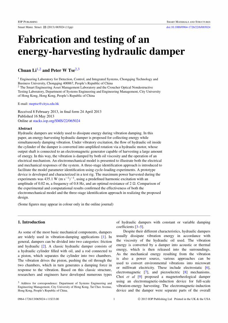
Figure 2. Prototype device.
as a whole can be depicted using the electromechanicalmodel (i.e., equations (15) and (20)) with the six parametersf , a1, a2, a3, a4, and a5.
3. Prototype device and experimental approach
3.1. Construction of a prototype of the energy-harvestinghydraulic damper
Following the design for the energy-harvesting damperoutlined in section 2.3, a prototype device was developedin the Engineering Laboratory for Detection, Control andIntegrated Systems at Chongqing Technology and BusinessUniversity. A photograph of the prototype device is providedin figure 2. An oil cylinder (MOB40× 80, Anshun) was fixedto the host structure of the device, and a cap was manufacturedto accommodate one of the cylinder’s two rods. Next, weconnected the two chambers of the cylinder to the two portsof a hydraulic motor (BMM8-MAE, Heye), and connectedthe output shaft of the motor to an electromagnetic generator(DC-6616-006B, Shinano Kenshi) via a customized couplingmechanism. The housing of the generator was fixed to thecap. To supply hydraulic oil to the system and exhaust it fromthe system as necessary, a release valve (DN8, Ameco) wasconnected to one of the cylinder’s ports. A cable was used toconnect the generator to the load resistor.
The specifications of the device are listed in table 1.
3.2. Experimental set-up
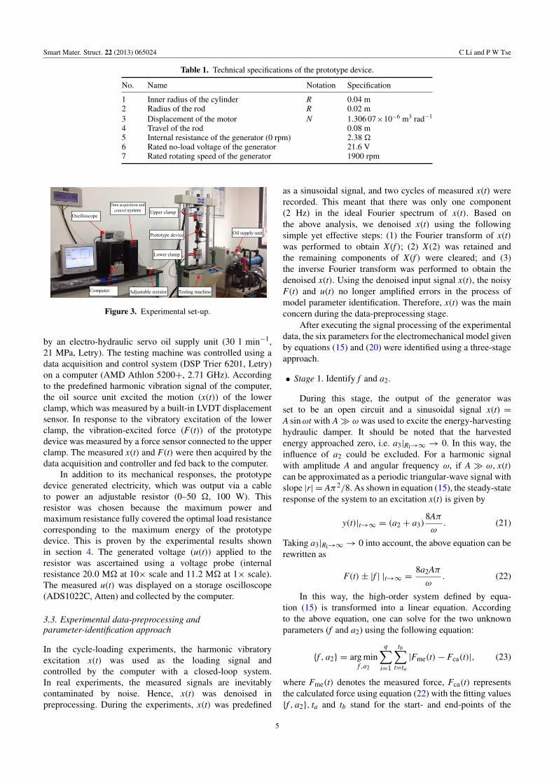
Cycle-loading experiments have been used to characterize thedynamic responses of different vibration components [26].Using the cycle-loading approach, a harmonic vibration signalis applied to the two terminals of the vibration component.The vibration-induced force between the two terminals canthen be measured. By calculating the relationship betweenthe force signal and the vibration signal, one can identifythe mechanical characteristics of the vibration components.In this study, the cycle-loading approach is also employed tocharacterize the energy-harvesting hydraulic damper.
As shown in figure 3, an electro-hydraulic servofatigue-testing machine (PLD-20, Letry) was used to carryout the cycle-loading experiments. The two terminals of thespecimen were held by two clamps (the lower clamp andthe upper clamp) of the testing machine, which was powered
4
Smart Mater. Struct. 22 (2013) 065024 C Li and P W Tse
Table 1. Technical specifications of the prototype device.
No. Name Notation Specification
1 Inner radius of the cylinder R 0.04 m2 Radius of the rod R 0.02 m3 Displacement of the motor N 1.306 07×10−6 m3 rad−1
4 Travel of the rod 0.08 m5 Internal resistance of the generator (0 rpm) 2.38 �6 Rated no-load voltage of the generator 21.6 V7 Rated rotating speed of the generator 1900 rpm
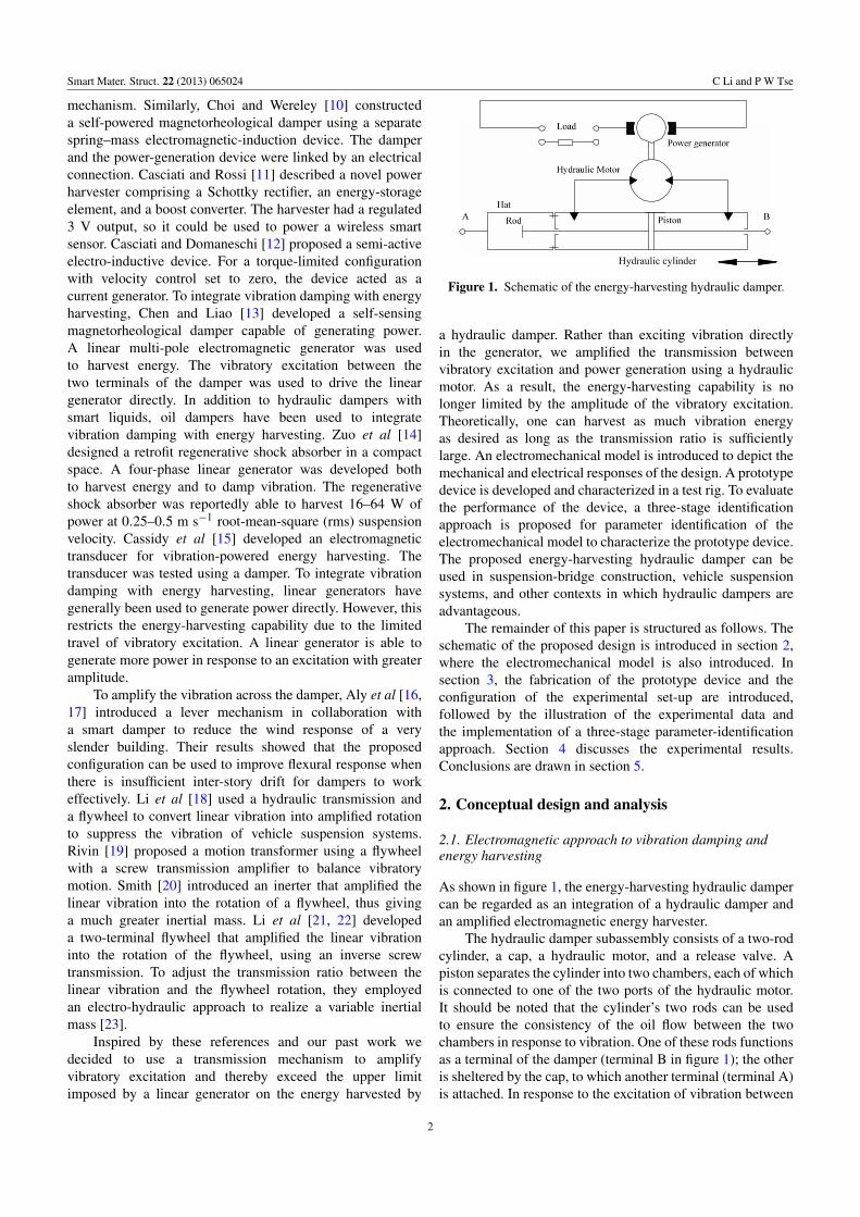
Figure 3. Experimental set-up.
by an electro-hydraulic servo oil supply unit (30 l min−1,21 MPa, Letry). The testing machine was controlled using adata acquisition and control system (DSP Trier 6201, Letry)on a computer (AMD Athlon 5200+, 2.71 GHz). Accordingto the predefined harmonic vibration signal of the computer,the oil source unit excited the motion (x(t)) of the lowerclamp, which was measured by a built-in LVDT displacementsensor. In response to the vibratory excitation of the lowerclamp, the vibration-excited force (F(t)) of the prototypedevice was measured by a force sensor connected to the upperclamp. The measured x(t) and F(t) were then acquired by thedata acquisition and controller and fed back to the computer.
In addition to its mechanical responses, the prototypedevice generated electricity, which was output via a cableto power an adjustable resistor (0–50 �, 100 W). Thisresistor was chosen because the maximum power andmaximum resistance fully covered the optimal load resistancecorresponding to the maximum energy of the prototypedevice. This is proven by the experimental results shownin section 4. The generated voltage (u(t)) applied to theresistor was ascertained using a voltage probe (internalresistance 20.0 M� at 10× scale and 11.2 M� at 1× scale).The measured u(t) was displayed on a storage oscilloscope(ADS1022C, Atten) and collected by the computer.
3.3. Experimental data-preprocessing andparameter-identification approach
In the cycle-loading experiments, the harmonic vibratoryexcitation x(t) was used as the loading signal andcontrolled by the computer with a closed-loop system.In real experiments, the measured signals are inevitablycontaminated by noise. Hence, x(t) was denoised inpreprocessing. During the experiments, x(t) was predefined
as a sinusoidal signal, and two cycles of measured x(t) wererecorded. This meant that there was only one component(2 Hz) in the ideal Fourier spectrum of x(t). Based onthe above analysis, we denoised x(t) using the followingsimple yet effective steps: (1) the Fourier transform of x(t)was performed to obtain X(f ); (2) X(2) was retained andthe remaining components of X(f ) were cleared; and (3)the inverse Fourier transform was performed to obtain thedenoised x(t). Using the denoised input signal x(t), the noisyF(t) and u(t) no longer amplified errors in the process ofmodel parameter identification. Therefore, x(t) was the mainconcern during the data-preprocessing stage.
After executing the signal processing of the experimentaldata, the six parameters for the electromechanical model givenby equations (15) and (20) were identified using a three-stageapproach.
• Stage 1. Identify f and a2.
During this stage, the output of the generator wasset to be an open circuit and a sinusoidal signal x(t) =A sinωt with A� ω was used to excite the energy-harvestinghydraulic damper. It should be noted that the harvestedenergy approached zero, i.e. a3|Rl→∞ → 0. In this way, theinfluence of a2 could be excluded. For a harmonic signalwith amplitude A and angular frequency ω, if A � ω, x(t)can be approximated as a periodic triangular-wave signal withslope |r| = Aπ2/8. As shown in equation (15), the steady-stateresponse of the system to an excitation x(t) is given by
y(t)|t→∞ = (a2 + a3)8Aπ
ω. (21)
Taking a3|Rl→∞→ 0 into account, the above equation can berewritten as
F(t)± |f | |t→∞ =8a2Aπ
ω. (22)
In this way, the high-order system defined by equa-tion (15) is transformed into a linear equation. Accordingto the above equation, one can solve for the two unknownparameters (f and a2) using the following equation:
{f , a2} = arg minf ,a2
q∑i=1
tb∑t=ta
|Fme(t)− Fca(t)|, (23)
where Fme(t) denotes the measured force, Fca(t) representsthe calculated force using equation (22) with the fitting values{f , a2}, ta and tb stand for the start- and end-points of the
5
Smart Mater. Struct. 22 (2013) 065024 C Li and P W Tse
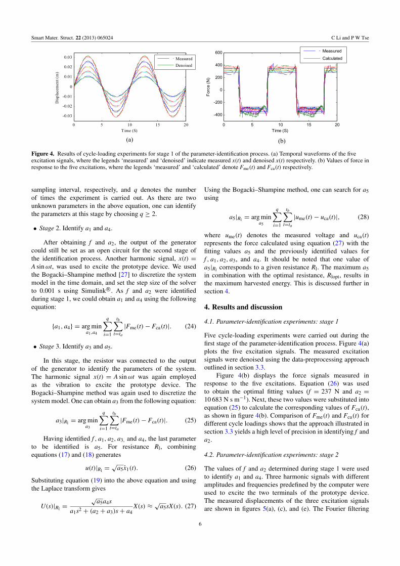
Figure 4. Results of cycle-loading experiments for stage 1 of the parameter-identification process. (a) Temporal waveforms of the fiveexcitation signals, where the legends ‘measured’ and ‘denoised’ indicate measured x(t) and denoised x(t) respectively. (b) Values of force inresponse to the five excitations, where the legends ‘measured’ and ‘calculated’ denote Fme(t) and Fca(t) respectively.
sampling interval, respectively, and q denotes the numberof times the experiment is carried out. As there are twounknown parameters in the above equation, one can identifythe parameters at this stage by choosing q ≥ 2.
• Stage 2. Identify a1 and a4.
After obtaining f and a2, the output of the generatorcould still be set as an open circuit for the second stage ofthe identification process. Another harmonic signal, x(t) =A sinωt, was used to excite the prototype device. We usedthe Bogacki–Shampine method [27] to discretize the systemmodel in the time domain, and set the step size of the solverto 0.001 s using Simulink R©. As f and a2 were identifiedduring stage 1, we could obtain a1 and a4 using the followingequation:
{a1, a4} = arg mina1,a4
q∑i=1
tb∑t=ta
|Fme(t)− Fca(t)|. (24)
• Stage 3. Identify a3 and a5.
In this stage, the resistor was connected to the outputof the generator to identify the parameters of the system.The harmonic signal x(t) = A sinωt was again employedas the vibration to excite the prototype device. TheBogacki–Shampine method was again used to discretize thesystem model. One can obtain a3 from the following equation:
a3|Rl = arg mina3
q∑i=1
tb∑t=ta
|Fme(t)− Fca(t)|. (25)
Having identified f , a1, a2, a3, and a4, the last parameterto be identified is a5. For resistance Rl, combiningequations (17) and (18) generates
u(t)|Rl =√
a5x1(t). (26)
Substituting equation (19) into the above equation and usingthe Laplace transform gives
U(s)|Rl =
√a5a4s
a1s2 + (a2 + a3)s+ a4X(s) ≈
√a5sX(s). (27)
Using the Bogacki–Shampine method, one can search for a5using
a5|Rl = arg mina5
q∑i=1
tb∑t=ta
|ume(t)− uca(t)|, (28)
where ume(t) denotes the measured voltage and uca(t)represents the force calculated using equation (27) with thefitting values a5 and the previously identified values forf , a1, a2, a3, and a4. It should be noted that one value ofa5|Rl corresponds to a given resistance Rl. The maximum a5in combination with the optimal resistance, Rlopt, results inthe maximum harvested energy. This is discussed further insection 4.
4. Results and discussion
4.1. Parameter-identification experiments: stage 1
Five cycle-loading experiments were carried out during thefirst stage of the parameter-identification process. Figure 4(a)plots the five excitation signals. The measured excitationsignals were denoised using the data-preprocessing approachoutlined in section 3.3.
Figure 4(b) displays the force signals measured inresponse to the five excitations. Equation (26) was usedto obtain the optimal fitting values (f = 237 N and a2 =
10 683 N s m−1). Next, these two values were substituted intoequation (25) to calculate the corresponding values of Fca(t),as shown in figure 4(b). Comparison of Fme(t) and Fca(t) fordifferent cycle loadings shows that the approach illustrated insection 3.3 yields a high level of precision in identifying f anda2.
4.2. Parameter-identification experiments: stage 2
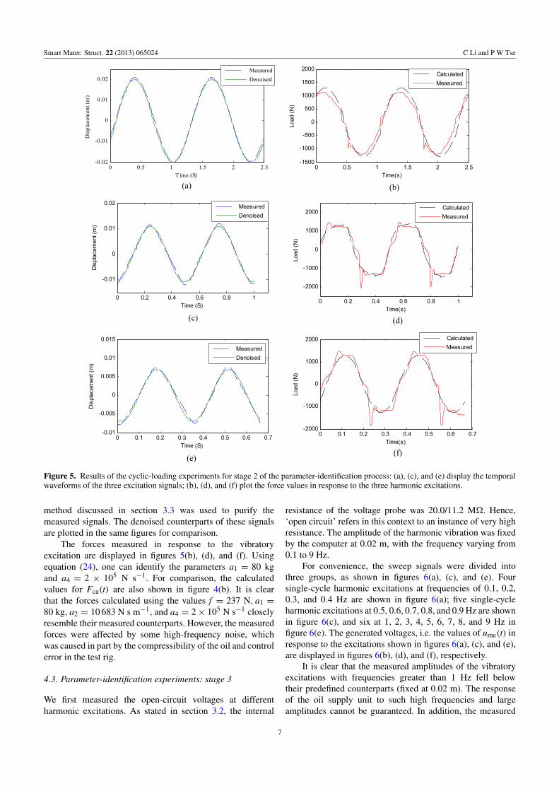
The values of f and a2 determined during stage 1 were usedto identify a1 and a4. Three harmonic signals with differentamplitudes and frequencies predefined by the computer wereused to excite the two terminals of the prototype device.The measured displacements of the three excitation signalsare shown in figures 5(a), (c), and (e). The Fourier filtering
6
Smart Mater. Struct. 22 (2013) 065024 C Li and P W Tse
Figure 5. Results of the cyclic-loading experiments for stage 2 of the parameter-identification process: (a), (c), and (e) display the temporalwaveforms of the three excitation signals; (b), (d), and (f) plot the force values in response to the three harmonic excitations.
method discussed in section 3.3 was used to purify themeasured signals. The denoised counterparts of these signalsare plotted in the same figures for comparison.
The forces measured in response to the vibratoryexcitation are displayed in figures 5(b), (d), and (f). Usingequation (24), one can identify the parameters a1 = 80 kgand a4 = 2 × 10⁵ N s−1. For comparison, the calculatedvalues for Fca(t) are also shown in figure 4(b). It is clearthat the forces calculated using the values f = 237 N, a1 =
80 kg, a2 = 10 683 N s m−1, and a4 = 2× 10⁵ N s−1 closelyresemble their measured counterparts. However, the measuredforces were affected by some high-frequency noise, whichwas caused in part by the compressibility of the oil and controlerror in the test rig.
4.3. Parameter-identification experiments: stage 3
We first measured the open-circuit voltages at differentharmonic excitations. As stated in section 3.2, the internal
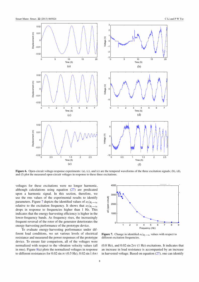
resistance of the voltage probe was 20.0/11.2 M�. Hence,‘open circuit’ refers in this context to an instance of very highresistance. The amplitude of the harmonic vibration was fixedby the computer at 0.02 m, with the frequency varying from0.1 to 9 Hz.
For convenience, the sweep signals were divided intothree groups, as shown in figures 6(a), (c), and (e). Foursingle-cycle harmonic excitations at frequencies of 0.1, 0.2,0.3, and 0.4 Hz are shown in figure 6(a); five single-cycleharmonic excitations at 0.5, 0.6, 0.7, 0.8, and 0.9 Hz are shownin figure 6(c), and six at 1, 2, 3, 4, 5, 6, 7, 8, and 9 Hz infigure 6(e). The generated voltages, i.e. the values of ume(t) inresponse to the excitations shown in figures 6(a), (c), and (e),are displayed in figures 6(b), (d), and (f), respectively.
It is clear that the measured amplitudes of the vibratoryexcitations with frequencies greater than 1 Hz fell belowtheir predefined counterparts (fixed at 0.02 m). The responseof the oil supply unit to such high frequencies and largeamplitudes cannot be guaranteed. In addition, the measured
7
Smart Mater. Struct. 22 (2013) 065024 C Li and P W Tse
Figure 6. Open-circuit voltage-response experiments: (a), (c), and (e) are the temporal waveforms of the three excitation signals; (b), (d),and (f) plot the measured open-circuit voltages in response to these three excitations.
voltages for these excitations were no longer harmonic,although calculations using equation (27) are predicatedupon a harmonic signal. In this section, therefore, weuse the rms values of the experimental results to identifyparameters. Figure 7 depicts the identified values of a5|Rl→∞
relative to the excitation frequency. It shows that a5|Rl→∞
drops in response to frequencies higher than 1 Hz. Thisindicates that the energy-harvesting efficiency is higher in thelower-frequency bands. As frequency rises, the increasinglyfrequent reversal of the rotor of the generator deteriorates theenergy-harvesting performance of the prototype device.
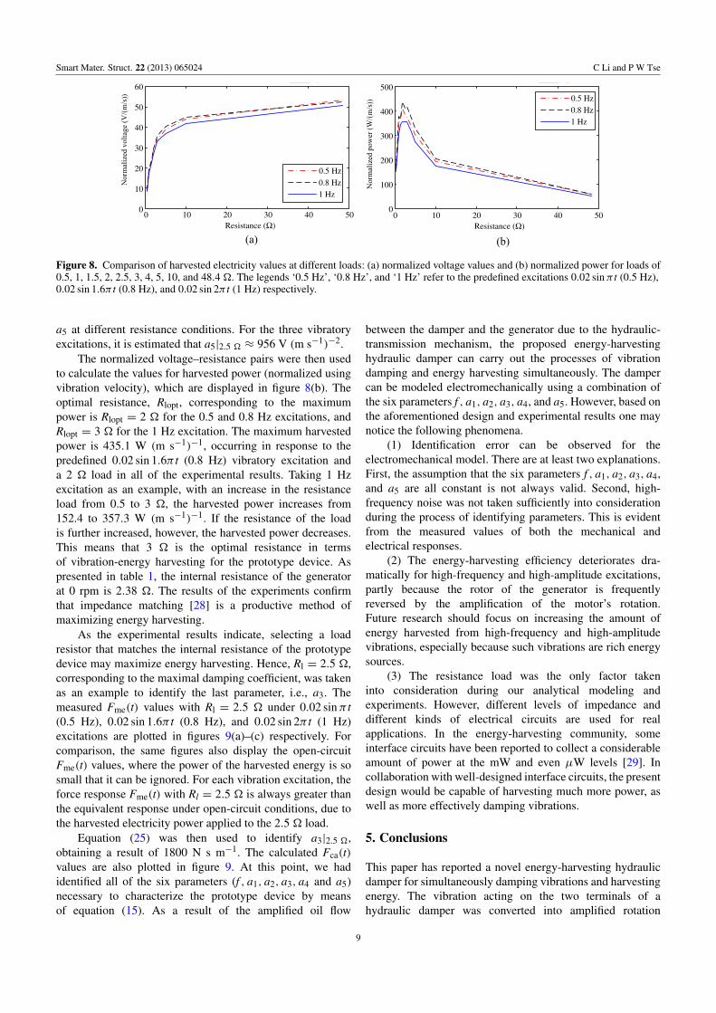
To evaluate energy-harvesting performance under dif-ferent load conditions, we set various levels of electricalresistance and measured the power responses of the prototypedevice. To ensure fair comparison, all of the voltages werenormalized with respect to the vibration velocity values (allin rms). Figure 8(a) plots the normalized voltages in responseto different resistances for 0.02 sinπ t (0.5 Hz), 0.02 sin 1.6π t
Figure 7. Change in identified a5|Rl→∞ values with respect todifferent excitation frequencies.
(0.8 Hz), and 0.02 sin 2π t (1 Hz) excitations. It indicates thatan increase in load resistance is accompanied by an increasein harvested voltage. Based on equation (27), one can identify
8
Smart Mater. Struct. 22 (2013) 065024 C Li and P W Tse
60
50
40
30
20
10
00 10 20 30 40
0.5 Hz
50Resistance (Ω)
0 10 20 30 40 50Resistance (Ω)
0.8 Hz1 Hz
0.5 Hz0.8 Hz1 Hz
500
400
300
200
100
0
Figure 8. Comparison of harvested electricity values at different loads: (a) normalized voltage values and (b) normalized power for loads of0.5, 1, 1.5, 2, 2.5, 3, 4, 5, 10, and 48.4 �. The legends ‘0.5 Hz’, ‘0.8 Hz’, and ‘1 Hz’ refer to the predefined excitations 0.02 sinπ t (0.5 Hz),0.02 sin 1.6π t (0.8 Hz), and 0.02 sin 2π t (1 Hz) respectively.
a5 at different resistance conditions. For the three vibratoryexcitations, it is estimated that a5|2.5 � ≈ 956 V (m s−1)−2.
The normalized voltage–resistance pairs were then usedto calculate the values for harvested power (normalized usingvibration velocity), which are displayed in figure 8(b). Theoptimal resistance, Rlopt, corresponding to the maximumpower is Rlopt = 2 � for the 0.5 and 0.8 Hz excitations, andRlopt = 3 � for the 1 Hz excitation. The maximum harvestedpower is 435.1 W (m s−1)−1, occurring in response to thepredefined 0.02 sin 1.6π t (0.8 Hz) vibratory excitation anda 2 � load in all of the experimental results. Taking 1 Hzexcitation as an example, with an increase in the resistanceload from 0.5 to 3 �, the harvested power increases from152.4 to 357.3 W (m s−1)−1. If the resistance of the loadis further increased, however, the harvested power decreases.This means that 3 � is the optimal resistance in termsof vibration-energy harvesting for the prototype device. Aspresented in table 1, the internal resistance of the generatorat 0 rpm is 2.38 �. The results of the experiments confirmthat impedance matching [28] is a productive method ofmaximizing energy harvesting.
As the experimental results indicate, selecting a loadresistor that matches the internal resistance of the prototypedevice may maximize energy harvesting. Hence, Rl = 2.5 �,corresponding to the maximal damping coefficient, was takenas an example to identify the last parameter, i.e., a3. Themeasured Fme(t) values with Rl = 2.5 � under 0.02 sinπ t(0.5 Hz), 0.02 sin 1.6π t (0.8 Hz), and 0.02 sin 2π t (1 Hz)excitations are plotted in figures 9(a)–(c) respectively. Forcomparison, the same figures also display the open-circuitFme(t) values, where the power of the harvested energy is sosmall that it can be ignored. For each vibration excitation, theforce response Fme(t) with Rl = 2.5 � is always greater thanthe equivalent response under open-circuit conditions, due tothe harvested electricity power applied to the 2.5 � load.
Equation (25) was then used to identify a3|2.5 �,obtaining a result of 1800 N s m−1. The calculated Fca(t)values are also plotted in figure 9. At this point, we hadidentified all of the six parameters (f , a1, a2, a3, a4 and a5)necessary to characterize the prototype device by meansof equation (15). As a result of the amplified oil flow
between the damper and the generator due to the hydraulic-transmission mechanism, the proposed energy-harvestinghydraulic damper can carry out the processes of vibrationdamping and energy harvesting simultaneously. The dampercan be modeled electromechanically using a combination ofthe six parameters f , a1, a2, a3, a4, and a5. However, based onthe aforementioned design and experimental results one maynotice the following phenomena.
(1) Identification error can be observed for theelectromechanical model. There are at least two explanations.First, the assumption that the six parameters f , a1, a2, a3, a4,and a5 are all constant is not always valid. Second, high-frequency noise was not taken sufficiently into considerationduring the process of identifying parameters. This is evidentfrom the measured values of both the mechanical andelectrical responses.
(2) The energy-harvesting efficiency deteriorates dra-matically for high-frequency and high-amplitude excitations,partly because the rotor of the generator is frequentlyreversed by the amplification of the motor’s rotation.Future research should focus on increasing the amount ofenergy harvested from high-frequency and high-amplitudevibrations, especially because such vibrations are rich energysources.
(3) The resistance load was the only factor takeninto consideration during our analytical modeling andexperiments. However, different levels of impedance anddifferent kinds of electrical circuits are used for realapplications. In the energy-harvesting community, someinterface circuits have been reported to collect a considerableamount of power at the mW and even µW levels [29]. Incollaboration with well-designed interface circuits, the presentdesign would be capable of harvesting much more power, aswell as more effectively damping vibrations.
5. Conclusions
This paper has reported a novel energy-harvesting hydraulicdamper for simultaneously damping vibrations and harvestingenergy. The vibration acting on the two terminals of ahydraulic damper was converted into amplified rotation
9

Smart Mater. Struct. 22 (2013) 065024 C Li and P W Tse
1500Open-circuit
1000
500
0
–500
–1000
–15000 1 2 3 4
Time (S) Time (S)
2.5 Ω
CalculatedOpen-circuit2.5 Ω
Calculated
Open-circuit2.5 Ω
Calculated
2000
1500
1000
500
0
–500
–1000
–15000 0.5 1 1.5 2 2.5
Time (S)
0 0.5 1 1.5 2
2000
1000
–1000
–2000
0
Figure 9. Force signals caused by predefined vibration excitations: (a) 0.02 sinπ t, (b) 0.02 sin 1.6π t, and (c) 0.02 sin 2π t. In the threefigures, the legends ‘2.5 �’, ‘open-circuit’, and ‘calculated’ refer to Fme(t) with a load resistance of 2.5 �,Fme(t) under open-circuitconditions, and Fca(t) with a load resistance of 2.5 �, respectively.
of a hydraulic motor. The output of the motor was thenconnected to the rotor of an electromagnetic generator,thereby yielding considerable power. In the process, someof the energy of the vibration was dissipated by theoil flow and some by the electromagnetic generation.An analytical model was proposed to depict both themechanical and electrical responses. A prototype device wasdeveloped and characterized in a test rig. To determine themodel parameters, we constructed a three-stage identificationapproach. The results of the experiments indicate that theoptimal resistance was 2–3�. The maximum harvested powerwas 435.1 W (m s−1)−1, occurring in response to a predefined0.02 sin 1.6π t (0.8 Hz) vibratory excitation. The experimentalresults validate the effectiveness of both the analyticalelectromechanical model and the three-stage identificationapproach. The present design, which integrates vibrationdamping and energy harvesting in a compact fashion, offersseveral potential energy-saving capabilities to engineeringapplications of hydraulic dampers. Further research onenergy-harvesting efficiency should focus on improvingresponse performance to high-frequency, high-amplitudevibration, and on developing well-designed interface circuits.
Acknowledgments
This work is supported by a grant from the City Universityof Hong Kong (7008187), the Key Project of the ChineseMinistry of Education (212143), the Natural Science
Foundation of CQ CSTC (2012JJJQ70001), and the Project ofChongqing Education Commission (KJ120720, KJ120727).
References
[1] Titurus B, du Bois J, Lieven N and Hansford R 2010A method for the identification of hydraulic dampercharacteristics from steady velocity inputs Mech. Syst.Signal Process. 24 2868–87
[2] Farjoud A, Ahmadian M, Craft M and Burke W 2012Nonlinear modeling and experimental characterization ofhydraulic dampers: effects of shim stack and orificeparameters on damper performance Nonlinear Dyn.67 1437–56
[3] Wang D H, Bai X X and Liao W H 2010 An integrated relativedisplacement self-sensing magnetorheological damper:prototyping and testing Smart Mater. Struct. 19 105008
[4] Noiray N and Schuermans B 2012 Theoretical andexperimental investigations on damper performance forsuppression of thermoacoustic oscillations J. Sound Vib.331 2753–63
[5] Witters M and Swevers J 2010 Black-box model identificationfor a continuously variable, electro-hydraulic semi-activedamper Mech. Syst. Signal Process. 24 4–18
[6] Roundy S, Wright P K and Rabaey J 2003 A study of lowlevel vibrations as a power source for wireless sensor nodesComput. Commun. 26 1131–44
[7] Arroyo E and Badel A 2011 Electromagnetic vibration energyharvesting device optimization by synchronous energyextraction Sensors Actuators A 171 266–73
[8] Li C, Hong D, Kwon K H and Jeong J 2012 Bond graph-basedanalysis of energy conversion in vibration–piezoelectricity
10
Smart Mater. Struct. 22 (2013) 065024 C Li and P W Tse
coupling and its application to a cantilever vibration energyharvester J. Vibroeng. 14 591–601
[9] Choi K M, Jung H J, Lee I W and Cho S W 2007 Feasibilitystudy of an MR damper-based smart passive control systememploying an electromagnetic induction device SmartMater. Struct. 16 2323–9
[10] Choi Y T and Wereley N M 2009 Self-poweredmagnetorheological dampers ASME J. Vib. Acoust.131 44–50
[11] Casciati F and Rossi R 2007 A power harvester for wirelesssensing applications Struct. Control Health Monit.14 649–59
[12] Casciati F and Domaneschi M 2007 Semi-activeelectro-inductive devices: characterization and modelingJ. Vib. Control 13 815–38
[13] Chen C and Liao W H 2012 A self-sensingmagnetorheological damper with power generation SmartMater. Struct. 21 025014
[14] Zuo L, Scully B, Shestani J and Zhou Y 2010 Design andcharacterization of an electromagnetic energy harvester forvehicle suspensions Smart Mater. Struct. 19 045003
[15] Cassidy I L, Scruggs J T, Behrens S and Gavin H P 2011Design and experimental characterization of anelectromagnetic transducer for large-scale vibratory energyharvesting applications J. Intell. Mater. Syst. Struct.22 2009–14
[16] Aly A M, Zasso A and Resta F 2011 On the dynamics of avery slender building under winds: response reductionusing MR dampers with lever mechanism Struct. Des. TallSpec. Build. 20 541–53
[17] Aly A M, Zasso A and Resta F 2011 Proposed configurationsfor the use of smart dampers with bracings in tall buildingsSmart Mater. Res. 2012 251543
[18] Li C, Jiang P, Wang S L, Wang Y X and Jiao Z J 2011 Designof novel hydraulic flywheels for vehicle suspensions Adv.Sci. Lett. 4 1586–90
[19] Rivin E I 2003 Passive Vibration Isolation (New York: ASMEPress)
[20] Smith M C 2002 Synthesis of mechanical networks: the inerterIEEE Trans. Autom. Control 47 1648–62
[21] Li C, Liang M, Wang Y X and Dong Y T 2012 Vibrationsuppression using two-terminal flywheel. Part I: modelingand characterization J. Vib. Control 18 1096–105
[22] Li C, Liang M, Wang Y X and Dong Y T 2012 Vibrationsuppression using two-terminal flywheel. Part II:application to vehicle passive suspension J. Vib. Control18 1353–65
[23] Li C and Liang M 2012 Characterization and modeling of anovel electro-hydraulic variable two-terminal mass deviceSmart Mater. Struct. 21 025004
[24] Lin T C 2007 Realization and verifications of inerter modelsMaster’s Thesis National Taiwan University
[25] Jang S M, Seo H J, Park Y S, Park H I and Choi J Y 2012Design and electromagnetic field characteristic analysis of1.5 kW small scale wind power generator for substitution ofNd–Fe–B to errite permanent magnet IEEE Trans. Magn.48 2933–6
[26] Wang S L, Zhao Y, Zhou J, Li C and Li X 2013 Staticresponse of stranded wire helical springs to axial loads: atwo-state model IMechE J. Mech. Eng. Sci. doi:10.1177/0954406212466520
[27] Safikhani A R, Hashemi R and Assempour A 2009 Somenumerical aspects of necking solution in prediction of sheetmetal forming limits by strain gradient plasticity Mater.Des. 30 727–40
[28] Green P L, Worden K, Atallah K and Sims N D 2012 Thebenefits of Duffing-type nonlinearities and electricaloptimisation of a mono-stable energy harvester under whiteGaussian excitations J. Sound Vib. 331 4504–17
[29] Volkmann M H, Sahu A, Fourie C J and Mukhanov O A 2013Implementation of energy efficient single flux quantumdigital circuits with sub-aJ/bit operation Supercond. Sci.Technol. 26 015002
11
Related Documents


![DESIGN AND FABRICATION OF THEFT PROOF VEHICLE USING … · Automobile Power Hydraulic Braking System By Vibratory Energy [3] by explains concept of automobile power hydraulic braking](https://static.cupdf.com/doc/110x72/5e211a1bf4e24f3ddc520feb/design-and-fabrication-of-theft-proof-vehicle-using-automobile-power-hydraulic-braking.jpg)