FAB OPERATING MANUAL FAB OPERATING MANUAL FAB OPERATING MANUAL FAB OPERATING MANUAL FAB OPERATING MANUAL ARRAY ELECTRONIC CO.,LTD

Welcome message from author
This document is posted to help you gain knowledge. Please leave a comment to let me know what you think about it! Share it to your friends and learn new things together.
Transcript

FAB OPERATING MANUALFAB OPERATING MANUALFAB OPERATING MANUALFAB OPERATING MANUALFAB OPERATING MANUAL
A R R A Y E L E C T R O N I C C O . , L T D

Preface
Thank you for purchasing FAB Intelligent Controls Series of our company.
This shows that you have a full understanding and a good knowledge of these
products. However, for the purpose of allowing you to use these products better,
you are requested to take some time to read this manual before operation. You will
find more advantageous properties of the products, and it will be more convenient
for you to operate these products.
Series FAB Intelligent Controls is a Type of intelligent control which uses the
function block for programming and is provided with an LCD liquid crystal dis-
play panel. It realizes the control functions of PLC, which required a large section
of instructions and program in the past, only by a function block. When several
function blocks are linked together in a specific way, the relatively complicated
control functions can be implemented so that the programming can be simplified.
FAB intelligent controls Series can be used very extensively. It can be used in
a complete supply for the automation of mechanical equipments, flowcontrol, the
building management automatic control and the other fields, and it makes the
automation control go to every space of our life. This manual will describe in
details the function characteristics and operating methods of FAB controls Series.
Attention:
(1) Copyright of this manual and patent of this machine are the property of
ARRAY ELECTRONIC CO., LTD. No reproduction or duplication of all or part
contents of this manual is permitted without consent in advance.
(2) Our company reserves the right to make changes in design for improvement
without notification.
(3) In case that something missing or shortage may be found in this manual, contact
our company directly and your comments will be appreciated. We will incorporate
your comments into the next revision.

Note:
1.It is prohibited to plug in or pull out the AF-C232 and LCD board when FAB
machine is powered.
2. The default of FAB password is 0001.
3. The default of FAB address is 000.
4. When programming for FAB, it is prohibited to connect the output of two
function block to one point, except CW function block.
For example.
The above way is wrong, and the right way is as follows:
&
>>>>>I2I3
M1
Q1
I1
&
I1
I2
I3
&
>>>>>
M1
M2
Q1

SAFETY GUIDE
This manual contains the precautions necessary for ensure your
personal safety as well as for protection the products and the con-
nected equipment. These precautions are highlighted with an triangle
“WARNING” symbol in this manual and are marked according to the
danger levels as following:
Danger It indicates that if appropriate precautions are not taken, serious
incidents of personal injuries and deaths or important damages or
losses to the properties will be caused.
Laution It indicates that if appropriate precaution are not taken,injuries of
immaturity or losses of properties will take place
Note:
Remind you to pay particular attentions to the important informa-
tion related to the products, disposal of products or the specific part
of documents.
Warning
Only the qualified personnel are allowed to debug and operate this
equipment. The qualified personnel are specified as those personnel
who carry out commissioning, grounding and apply the volume iden-
tification to the circuits, equipment and systems according to the
available safety practices and standards.
Note Only when this product is transported, stored assembled and in-
stalled in a proper way and operated and maintained according to the
recommendations, can it implement the functions properly and
reliably.
Use properly Take notice

Chapter I Brief Introduction to FAB
1
Chapter I Brief Introduction to FAB
FAB intelligent controller is a new type of programmable controller. As it is
programmed by the means of FBD (Function Block Diagram) , it is more simpleand easier to learn the programming of FAB than the conventional PLC program-ming (ladder diagram and instruction). In the design concept of the products ofFAB series, the machine in the conventional separating PLC is combined withwriter, and the program can be written directly on LCD front panel. As a result,the cost of the users can be reduced greatly, and moreover the great conve-nience can be provided to operators. Products of FAB series have a compactstructure with a small size and a light weight, and they are especially suitable to beused incorporated. Besides, FAB series intelligent controllers can be used inimplementing the close and remote communication networking and monitoring soas to allow such small sized device to have strong function. And FAB series canrealize telephone-control,voice prompting and dialing automatically functions,viajointly using with AF-MUL Voice Block . At present, FAB is widely used invarious fields of industry, agriculture, automation control for home, etc., and itreally can be applied everywhere.
1.1 Structure of FAB
Its main hardware structure consists of:
Basic function blocks and special function blocks,
Operation display panel
Real-time clock circuit
Programming interface
Telephone voice blocks
I/O terminals
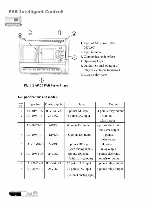
1. Input of AC power (85V ~ 240V)
2. Input terminal
3. Communication interface
4. Operating keys
5. Output terminal (Output of relay or electronic transistor)
6. LCD display panel
Fig. 1.1 AF-10 FAB Series Shape
FAB Intelligent Controller
2
Fig. 1.2 AF-20 FAB Series Shape
1 AF-10MR-A 85V-240VAC 6 points AC input 4 points relay output
2 AF-10MR-E 24VDC 6 points DC input 4 points
relay output
3 AF-10MT-E 24VDC 6 points DC input 4 points electronic
transistor output
4 AF-10MR-F 12VDC 6 points DC input 4 points
relay output
5 AF-10MR-D 24VDC 6points DC input 4 points
(with analog input) relay output
6 AF-10MT-D 24VDC 6points DC input 4 points electronic
(with analog input) transistor output
7 AF-20MR-A 85V-240VAC 12 points AC input 8 points relay output
8 AF-20MR-E 24VDC 12 points DC input 8 points relay output
(without analog input)
1. Input of AC power ( 85 ~
240VAC)
2. Input terminal
3. Communication interface
4. Operating keys
5. Output terminal (Output of
relay or electronic transistor)
6. LCD display panel
1.2 Specifications and models
13
2
4
5
6
Type No Power Supply Input OutputSerial No
w313_7

Chapter I Brief Introduction to FAB
3
9 AF-20MT-E 24VDC 12 points DC input 8 points electronic
(without analog input) transistor output
10 AF-20MR-F 12VDC 12 points DC input 8 points
(without analog input) relay output
11 AF-20MR-D 24VDC 12 points DC input 8 points
(with analog input) relay output
12 AF-20MT-D 24VDC 12 points DC input 8 points electronic
(with analog input) transistor output
13 AF-LCD FAB removable panel for programming with liquid crystal display
14 AF-C232 Interface between FAB and PC Modem for programming
15 AF-C485 Interface between 485bus and FAB for network monitor
16 AF-P485 Interface between 485bus and PC for network function
17 AF-M232 Interface between FAB and MODEM for remote control
and programming
18 AF-MUL Voice module to realize voice function
19 QUICK II FAB programming software
20 FAB-SCADA Telephone control and auto-dial function
Type No Power Supply Input Output
1.3 Features of FAB
1. Removable programming panel with Liquid Crystal Display There is an operating panel with LCD display on the front side of FAB.
You can use the operating keys on this panel to directly edit the controlprogram for FAB. Moreover, this LCD display panel is removable, and itcan be set up flexibly according to your needs. When you need it, it can beplugged in, and when you don’t need it, it can be pulled out and replacedwith an ordinary front panel, As a result, your cost for using it can be
decreased by a big margin.
Note This panel can be plugged in or pulled out only after the power has been turned off.
Serial No

FAB Intelligent Controller
4
2. Exquisite and compact design If you are thinking of making your equipment become more exquisite, FAB
will be your best partner and it only needs to occupy your space of 90mm ´71mm ´ 58mm (Size of AF-10 Series); 90mm ´ 126mm ´ 58mm(Size of AF-20Series)
3. With the logic blocks used for programming, the program storage capacity islarge
The control functions of FAB can be implemented only with a functionblock, but it was implemented by conventional PLC with a large section ofprogram. If several function blocks are linked together in a specific way, therelatively complicated control functions can be implemented. As FAB has astorage capacity of programs for up to 127 function blocks, there is a sufficientapplication resource for you to satisfy the requirements for the complicatedcontrol. And once the programs are written in, they will never be lost.
4. QUICK II: a free-of-charge programming software The programma can be edited diredly on the LCD panel or on PC by using
programming software QUICKII and then be written into the memory of FAB.QUICK II is a very friendly man-machine programming interface. It can notonly edit the function diagrams, but also analogously run the written program. Itprovides an off-line testing function to the users so as avoid a lot of inconve-niences in on-line testing. QUICK II will not only guide you to implement theedition of the control programs, but also to perform the real-time monitor-ing for the field environment and the operation conditions of FAB.
5. Real-time clock function FAB Series intelligent controllers have a real-time recording function. And
it can execute the operations according to your required schedule. You can set asmany as up to 127 different time intervals, and it is most suitable to be used forthe systems which require time control.
6. Analog input and transmission In addition to receiving the switching input, FAB can also receive the
analog input to implement the control over temperature, humidity, pressure,flow, level unit, etc., and transmit them remotely to PC for monitoring.

Chapter I Brief Introduction to FAB
5
7. To implement the remote programming and the supervision and controlof data acquisition through MODEM
When you need to implement programming, writing and modifyingprograms for FAB controllers in a relatively far distance, it is only necessaryto connect FAB to MODEM through telephone line, and it is also possible toperform data acquisition and real-time supervision and control throughMODEM.
8. Security cipher code function FAB itself is provided with an absolute security for the programs
written by you. You can set your own cipher code before you writeprograms. The programs can be modified only after the correct cipher codeis entered.
9. Telephone function FAB is equiped with telephone and voice function blocks. It is
possible to dial directly through telephone line ( set the telephone No.beforehand, FAB can be dialed automatically when the conditions aresatisfied.), so as to implement notice or alarm functions. Moreover, FAB canalso receive the signals transmitted from the far end through the telephoneline in order to control the terminal equipment.
Note It is necessary to configure AF-MUL multi-function voice block for the implementation of telephone function and voice function.
10. Voice function It is first time for FAB to apply the voice recording and broadcasting
functions in the automatic control industry, creating the intelligent control-lers which can speak and implementing the voice prompting function.
11. Networking function FAB has a networking function. Though 485 buses 255 FABs can be
made up into a network to implement the real-time supervision and controlon the same PC.
12. Fab-scada monitoring and control functions.
13. With the intermediate relay added, you are allowed to process easily more
complicated control requinements.

FAB Intelligent Controller
6
RESUMERESUME

Chapter II Installation and wiring of FAB
7
2.1 Installation
2.1.1. Installation method
As FAB has a small size, it is suitable for fitting- inside machine, and installation is
quite sample:
1. To use standard DIN rail for installation of FAB as shown in Fig. 2.1.
2. To use the screw holes on FAB for installation of FAB.
Fig.2.1 Use standard DIN rail for installation of FAB
Caution:1.The LCD board of FAB is removable. Just prizing open it by a
screwdriver, then it can be easily pulled out. Please operate as follows:
2 .Do not remove LCD while being powered. Otherwise the machine will
be broken even worse it will endanger personal safety of the operator.
Chapter II Installation and wiring of FAB
DIN rail
Fig.2.2 Remove LCD board correctly

FAB Intelligent Controller
8
Fig2.4 AF-20 FAB Series installation dimensions (Unit: mm)
2.1.2 Dimension
Fig2.3 AF-10 FAB Series installation dimensions (Unit: mm)

Chapter II Installation and wiring of FAB
9
2.2 Wiring of FAB
The screwdriver with a tip width of 3mm is used for wiring of FAB. The cross
sections of the wires are determined according to the following dimensions:
2.2.1 Connection of power supply
1 For AF-10MR-A and AF-10MR-A(AC type)FABS,the rated power supply
requirements are 110VAC and 220VAC(85VAC-240VAC), 50/60HZ. At a Voltage
of 220VAC, the current consumptions for each type are 26mA and 50mA.
2. For AF-10MR-D/AF-10MT-D/AF-20MR-D and AF-10MT-E/AF-20MT-E/AF-
20MT-D/AF-10MD-E/AF-20MR-E(DC type )FABs,the power supply require-
ment is 24VDC(24.4VDC-28.8VDC)
3 The power supply requirement of AF-10MR-F and AF-20MR-F is 12 VDC
2.2.2 connecting FAB input
The input to FAB can be either the digital such as on/off switches, photo-
electric damper, sunshine switch, etc., or the analog such as pressure, level
element, temperature, humidity, flow, etc. The specific requirements are as
follows:
1 2.5mm2
2 1.5mm2
The power connection for FAB is as shown in the following figure
AF-10MR-A and AF-20MR-A
Fig2.5 AC Type Fig2.6 DC Type

FAB Intelligent Controller
1 0
Switch status 0 <40VAC
Input current <0.24mA <1.5mA <1.5mA <2.8mA
Switch status 1 >=80VAC >=15VDC >=15VD C >=8VDC Input current Typical 0.24mA Typical 3mA Typical 3mA Typical 3mA
Analog input /
Note: 1.For AF-10MR-D,AF-10MT-D,AF-20MR-D and AF-20MT-D whichcan receive analog input, analog can be input though all input interfaces (I1-I6 orI1-Ic).They can automatically set to analog input or digital input as which is usedin the porogram.It will be recognized as analog inputs when the input terminal isconnected with AN function block, and it will be recognized as digital input whenthe input terminal is not connected with AN function block.You need to setanalog input firstly when you use FAB-SCADA software to supervise.2. The analog requires 0V ~ +10V voltage signals and it is divided equally in 0.1Vproportion. In programming, all the block parameters related to the analog arebased on the minimum precision of Class 0.1.3.It can be recognized as digital input when the input voltage is over 10.0v,and itcan not be recognized as analog input.4. As for the input of digital , when the switch status changes from 0 to 1, thetime of Status 1 must be greater than 50ms, and when the switch status changes
from 1 to 0, the time of Status 0 also must be greater than 50ms.
AF-10MR-AAF-20MR-A
Type
Demand
AF-10MR-DAF-10MT-DAF-20MR-DAF-20MR-D
AF-10MR-EAF-20MR-E
<5VDC <5VDC <5VDC
Proximity switchtype with directinput
2lines3lines4lines
2lines3lines4lines
Switch withglow lamp
When the closedcurrent of glow lampis less than or equalto 0.2mA, it can beconnected directly,and when the closedcurrent of glow lampis greater than 0.2mA, the glow lampshould be connectedthrough a relay or anadditional N-typedrive.
I1~I6/I1~Icreceivable analogvalue
AF-10MR-FAF-20MR-F
2lines3lines4lines
/ //
/ /
2lines3lines4lines

Chapter II Installation and wiring of FAB
1 1
Connecting FAB is shown as in the following figure:
Fig 2.7 AC Type Fig 2.8 DA Type ( E Type)
Fig 2.9 DC Type ( D Type)
2.2.3 Connecting of FAB Output
For AF-10MR-A/AF-20MR-A/AF-10MR-D/AF-20MR-D/AF-10MR-E /
AF-20MR-E /AF-10MR-F/AF-20MR-F FAB series, the output are relays.The
contacts of relays are isolated from the power supply and input.And for
AF-10MT-E/AF-20MT-E/AF-10MT-D and AF-20MT-D FAB Series,the output
are of transistor type ,provided with short circuit and overloading protection.It is
necessary to have a seperate power supply for the loads.

FAB Intelligent Controller
1 2
Fig 2.10 Realy Output
2. Requirements for the electronic transistor output
The load connected to FAB must have the following characteristics:
The maximum switch current can not exceed 2A;
when the switch is ON (Q=1), the maximum current is 2A.
The connection is as the following figure:
Fig2.11 Transistor Output
1. Requirements for the relay output
Various loads such as lamp, fluorescent tube, motor, contactor, etc., can be
connected to the outputs of FABs. The max. ON output current that can be
supplied by FAB, is 10A for the resistance load and 2A for the inductive load.
The connection is as the following figure:
The voltage between L+ 1 and M is less than 80VDC.
Note: M line should be connected to M of FAB power supply, and the
load should be directly connected the L+ 1 , and the load current
should be DC .
Indicating Lamp
Indicating Lamp
Chapter II Installation and wiring of FAB
1 3
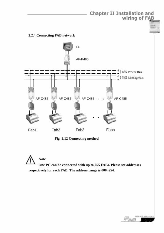
Note
One PC can be connected with up to 255 FABs. Please set addresses
respectively for each FAB. The address range is 000~254.
2.2.4 Connecting FAB network
○ ○
Fabn
AF-C485
Fab1 Fab2
AF-C485 AF-C485 AF-C485
○ ○
Fab3
AF-P485
}485 MessageBus
}485 Power BusA
B
PC
Fig 2.12 Connecting method
FAB Intelligent Controller
1 4
RESUMERESUME

Chapter III General Descripition of Function Blocks
1 5
Chapter III General Description of Function Blocks
FAB adopts the programming method with function blocks. 20 function blocks
are configured in total, and each block can achieve a specific control function indepen-
dently, e.g. time-delay ON, time-delay OFF, setting switch time, counter function,
etc. As several blocks are linked up in a specific way, the relatively complicated
control function can be realized. It will be more simple and apparent than the
conventional PLC instruction programming.
The following types of operator for FAB function blocks are available for
options:
1. Options of input port: I1 - IC(Input port), Q1- Q8 (Output port), Moo-M126
(Intermediate relay), HI (High potential status), LO (Low potential status), X (No
input connection), P0 - P9 (Telephone two-tone pulse)
2. Options for output port: Q1 ~ Q8 (Output port), Moo~M126 (Intermediate
relay).
3.1 General function block (GF)
There are 6 general function blocks in total as listed in the following table:
Table 1: General function blocks
Line diagram FAB function block Function
AND
ORParallel connection
of NO contacts
Series Connection of
NO contacts

FAB Intelligent Controller
1 6
3.1.1 AND
This function block is called “AND”, because only when I1, I2 and I3 are all in
statues 1, the status of Output Q will be 1 (i.e. the output is closed).
Logical frame of “AND”:
Phase inverter NOT
Dual commutator contact XOR
Parallel connection of
NC contacts
Serial connection of
NC contacts
NAND
NOR
I1I2 QI3
Serial connection of a certain number of NO
contacts is shown in the line diagram as
follows:
The symbol of “AND” is as
follows:
I 1 I 2 I 3 Q
0 0 0 0
0 0 1 0
0 1 0 0
0 1 1 0
1 0 0 0
1 0 1 0
1 1 0 0
1 1 1 1
I1 I2 I3

Chapter III General Descripition of Function Blocks
1 7
3.1.2 OR
This function block is called OR, because the status for at least one of inputs I1 or
I2 or I3 is 1 (i.e. closed), then output Q is 1.
Logical frame of “OR”:
3.1.3 NOT
This function block is called NOT, because the input status is 0, Output Q is 1, and
vice versa. In other words, NOT is the phase inverter for the input point.
Parallel connection of a certain number of NO
contacts, is shown in the electrical line dia-
gram as follows:
The symbol of “OR” is as shown
follows:
I1I2 QI3
I1I2I3
I 1 I 2 I 3 Q
0 0 0 0
0 0 1 1
0 1 0 1
0 1 1 1
1 0 0 1
1 0 1 1
1 1 0 1
1 1 1 1
The phase inverter is indicated in the line
diagram as follows:
The phase inverter is called “NOT”
in FAB, its symbol is as follows:
Q
I1I1

FAB Intelligent Controller
1 8
Logical frame of “NOT”:
3.1.4 NAND
This function block is called as NAND, because only when I1, I2 and I3 are all
in status 1 (i.e. closed), its Output Q is in status 0.
Logical frame of “NAND”:
The symbol of “NAND” in FAB is
shown as follows:
Parallel connection of certain number of NC
contacts, which is shown in the electrical
line diagram as follows:
I1I2I3
I1I2 QI3
I1 Q
0 1
1 0
I 1 I 2 I 3 Q
0 0 0 1
0 0 1 1
0 1 0 1
0 1 1 1
1 0 0 1
1 0 1 1
1 1 0 1
1 1 1 0
Chapter III General Descripition of Function Blocks
1 9
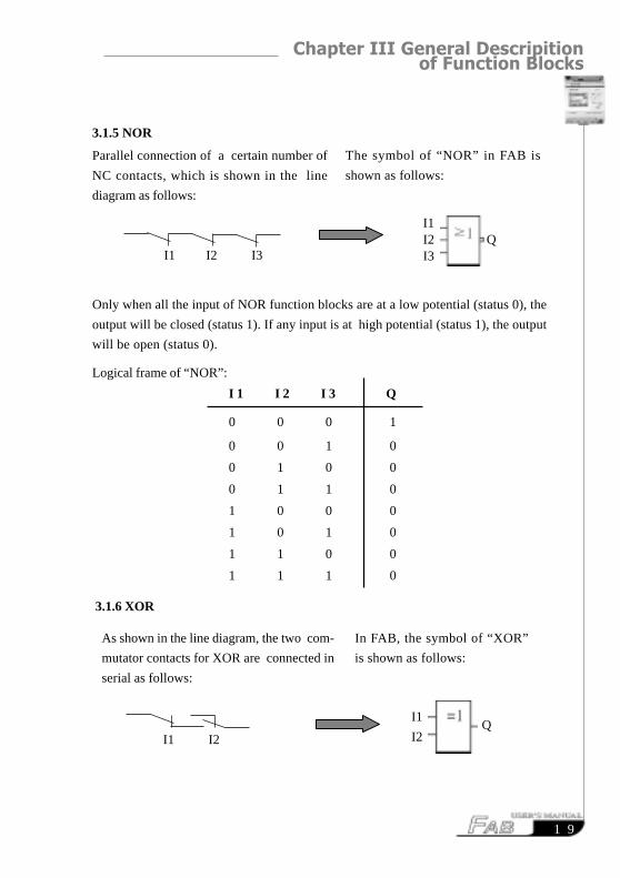
3.1.5 NOR
Only when all the input of NOR function blocks are at a low potential (status 0), the
output will be closed (status 1). If any input is at high potential (status 1), the output
will be open (status 0).
Logical frame of “NOR”:
3.1.6 XOR
Parallel connection of a certain number of
NC contacts, which is shown in the line
diagram as follows:
The symbol of “NOR” in FAB is
shown as follows:
As shown in the line diagram, the two com-
mutator contacts for XOR are connected in
serial as follows:
In FAB, the symbol of “XOR”
is shown as follows:
I1
I2Q
I1 I2
I1 I2 I3
I1I2 QI3
I 1 I 2 I 3 Q
0 0 0 1
0 0 1 0
0 1 0 0
0 1 1 0
1 0 0 0
1 0 1 0
1 1 0 0
1 1 1 0

FAB Intelligent Controller
2 0
When the status of input are not the same, the output status of XOR is 1.
Whern the status of input are the same,the ouput status of XOR is 0.
Logical frame of “XOR”:
3.2 Special function blocks (SF)
Function Representation Graph
DPR(ON time delay)
DDR(OFF time delay)
PLR(Pulse relay)
CW(Clock switch)
RS(RS relay)
I1 I2 Q
0 0 0
0 1 1
1 0 1
1 1 0

Chapter III General Descripition of Function Blocks
2 1
UCN(Up-counter)
DCN(Down- counter)
CPG(Clock pulse
generator)
RPR(Hold ON time-
delay relay)
MPLR(Single pulse
time relay)
TEL(Telephone dial-
ing block)
AN(analog input
block)
PLAY( Broadcast voice
sect ion & Selector
switch blocks)
MR(Recording voice
section& Selector
switch)

FAB Intelligent Controller
2 2
3.2.1 DPR
Line diagram/Symbol in FAB Pin Description
Time Sequence Frame:
Description:
When the status of TRG input changes from 0 to 1, the time-delay timer startstiming. If Input TRG holds status 1 for a sufficiently long time, the output willbe changed to 1 after the time T has elapsed. There is a time delay between theinput turning ON and the output turning On , that is why the ON time-delay isso called.
When the input TRG is Status 0, the output will reset to staus 0.
This function is applicable to remove vibrations of switches, delay start -up ofmotor, delay turning-on of lights, etc.
The assignment range for T is 0.01 - 99.99, and the time units can be setrespectively to hour (H), minute (M) and second (S). Its time accuracy can
reach 0.5 /00 S.
After TRG is trigged, the time
delay timer starts timing. (If
TRG stops triggering during the
timing of timer, the timer will ter-
minate the timing).
After time T, the output is on (the
output signal changes from 0 to 1).
If there is still trigging signal, when
time T is up, the output will be on.Output Q
Parameter
T
input
TRG
TRG
Q
T T T
0

Chapter III General Descripition of Function Blocks
2 3
3.2.2 DDR
Line diagram/Symbol in FAB Pin Description
Time Sequence Frame:
Description :
� When Input TRG is Status 1, Output Q is changed at once to Status 1. When
Input TRG is changed from 1 to 0 (when the descending edge comes), the internal
time delay timer of FAB is activated and Output Q is still remained in Status 1.
When the set time T is up, Output Q becomes 0 and the timer is reset l .
� If Input TRG changes from Status 1 to Status 0 again, the timer is activated again.
� Before the set time T is up, the timer and output can be reset via R (Reset) input.
TRG
R
Q T T
Input TRG
Input R
Parameter T
Output Q
Turn o n the timer of the time-delay off
relay ,when the input TRG (trigger)is
at the descending edge (changing from 1
to 0)The timer of disconnecting time-delay
relay is reset via R (Reset Input), and
Output Q is set to 0. (R has higher pri-
ority to TRG).
The output is disconnected (the Q sta-
tus is changed from 1 to 0) when the
time T elapses .
Input TRG is activated then the output
is turned on (Q=1) and is kept ON until
it is reset when the set time T is up.

FAB Intelligent Controller
2 4
� This function is applicable to the lighting of staircase, the control of barriers in
park, the control of water throttling valve, etc.
� The assignment range of T is 0.01 ~ 99.99, and the time units can be set
respectively to hour (H), minute (M) and second (S). Its time accuracy can reach
0.5% S.
3.2.3 PLR
Line diagram/Symbol in FAB Pin Description
Time Sequence Frame:
Description :
�Every time the trigger input TRG changes from status 0 to Status 1, the status of
Output Q will change accordingly (The status of Q will be reversed).
�Reset Q to Status 0 via Input R.
�After the power is ON or OFF, the pulse relay is reset and Output Q changes to 0.
TRG
R
Q
0
Input TRG
Input R
Output Q
Trigger input (TRG) makes the out-
put On and Off
The output Q is reset via R (Reset
input) (Q=0, R has a higher priority
to TRG).
Every time TRG changes from 0 to 1,the status of Q will be changed (i.e.from Status 0 to Statues 1 or viceversa).
Chapter III General Descripition of Function Blocks
2 5
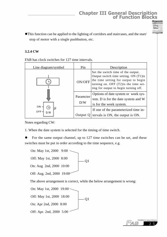
�This function can be applied to the lighting of corridors and staircases, and the start/
stop of motor with a single pushbutton, etc.
3.2.4 CW
FAB has clock switches for 127 time intervals.
Line diagram/symbol Pin Description
Notes regarding CW:
1. When the date system is selected for the timing of time switch.
� For the same output channel, up to 127 time switches can be set, and these
switches must be put in order according to the time sequence, e.g.
On: May 1st, 2000 9:00
Off: May 1st, 2000 8:00
On: Aug 2nd, 2000 10:00
Off: Aug. 2nd, 2000 19:00
The above arrangement is correct, while the below arrangement is wrong:
On: May 1st, 2000 19:00
Off: May 1st, 2000 18:00
On: Apr 2nd, 2000 8:00
Off: Apr. 2nd, 2000 5:00
ON/OFF
Paramcter
D/W
Output Q
Q1
Q1
Set the switch time of the output.Output switch time setting. ON (T1)isthe time setting for output to beginturning on. OFF (T2)is the time set-ting for output to begin turning off.
Options of date system or week sys-
tem. D is for the date system and W
is for the week system.
If one of the parameterized time in-
tervals is ON, the output is ON.

FAB Intelligent Controller
2 6
2. The range of T1 and T2
You can set T1,T2 anytime from 00:00:00 to 23:59:59. If you set T1 or T2 at
24:00:00, it means that you haven’tset the ON time or OFF time.(If you set T1 to
24:00:00, it means that you haven’t set ON time).
On the basis of this,we can set some special time intevals which haven’t been set
in the selected items by using Inter-relays and Logic interlock.Such as that there is
no item of the folloing.
6:00 on monday ,ON and 8:00 on Tuesday, OFF
How can we get the logic result of the above on the FAB panel?
Firstly . you should select MO ,and set it as follows.
Secondly .you should select TU,and set it as follows.
Then ,it can let Q1 switch on at 6:00 on Monday; switch off at 8:00 on Tuesday.
During the time setting the time switch,if two time-points(on and off),is set theoutput is ON in the time interval. Before the ON time the output keeps theformer status, and after the off time the output is off.
Q1
Q1
When you use QuickII Software, you can set time directly as follows:
ON MO :6:00
OFF TU :8:00
D/W 6:00
24:00
This setting means no OFF time
being set,not 24:00o’clock
D/W 24:00
8:00
This setting means no ON time
being set, not 24:00o’clock.
Chapter III General Descripition of Function Blocks
2 7
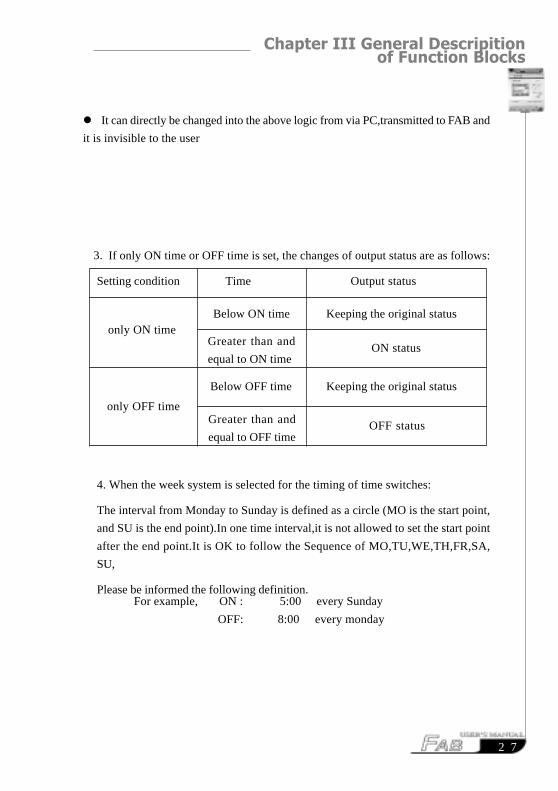
� It can directly be changed into the above logic from via PC,transmitted to FAB and
it is invisible to the user
For example, ON : 5:00 every Sunday
OFF: 8:00 every monday
If only ON time or OFF time is set, the changes of output status are as follows:
Setting condition Time Output status
4. When the week system is selected for the timing of time switches:
The interval from Monday to Sunday is defined as a circle (MO is the start point,
and SU is the end point).In one time interval,it is not allowed to set the start point
after the end point.It is OK to follow the Sequence of MO,TU,WE,TH,FR,SA,
SU,
Please be informed the following definition.
3.
only ON time
only OFF time
Below ON time Keeping the original status
ON status
Below OFF time Keeping the original status
Greater than and
equal to ON time
Greater than and
equal to OFF timeOFF status

FAB Intelligent Controller
2 8
Notes
MO: Monday MO-SU : every day from Monday to Sunday
TU : Tuesday MO-TH : every day from Monday to Thursday
WE : Wednesday MO-FR : every day from Monday to Friday
TH : Thursday MO-SA : every day from Monday to Saturday
FR : Friday FR-SU : every day from Friday to Satuday
SA : Saturday SA-SU : every day from Satuday to Sunday
SU : Sunday
It can be programmed by three blocks as follows:
D/WSU 24:00
5:00
D/WMO 8:00
24:00
M00
M00
M00 Q1
� As for the case that only OFF time is only set without ON time, e.g. it is only
set to be OFF at 5:00 from Monday to Thursday, and FAB can turn OFF the
output after 5:00 everyday from MO ~ TH, as to when it is going to be ON, it
depends on other factors (the original status will be maintained for Friday, Satur-
day and Sunday).
5. Whether the date system or the week system is selected, the time intervals for
the time of the same date should be arranged in chronological order, for example:

Chapter III General Descripition of Function Blocks
2 9
May 1st, 2000 9:00 ON
11:00 OFF
12:00 ON
17:00 OFF
May 1st, 2000 9:00 ON
11:00 OFF
May 1st 8:00 ON
8:30 OFF
Q1(ERROR)
FAB will turn OFF the output
from 9:00 to 11:00.
MO 9:00 ON
11:00 OFF
15:00 ON
18:00 OFF
MO 9:00 ON
11:00 OFF
6:30 ON
8:30 OFF
Q1(OK)
Q1(ERROR)
FAB will turn OFF the output
from 9:00 to 11:00.
Note: this phenomenon is called as a principle of the later command
surpassing the former command.

FAB Intelligent Controller
3 0
6. When the week system is selected, if ON is set at 8:00 and Off is set at 9:00
of MO~ TH, FR,SA and SU will maintain the former status, ie., the original
ON status will be kept as ON and the original OFF status will be kept as
OFF.
7. When you program by using LCD board, having selected Week system, it is
only neccessory to set T1 and T2, and it is meaningless to set D . And it is
neccessory to set D when you have selected Day system. D is the setting of
data, T1 is the setting of ON time,and T2 is the setting of OFF time.
8. Clock hold circuit
For FAB, when there is a power failure or a power cutting off, the internal
clock can continue to run. The time that FAB can maintain the internal clock
to run depends on the temperature of racks, and when the temperature of
racks is 25 Cdegree, the clock can continue the normal operation more than
100 hours.
9. Conflict between time intervals:
When using the time intervals to set the ON/OFF time for the clock, the clock
switch will make the output ON at the ON time unless it has already been
ON, and the clock switch will make the output OFF at the OFF time unless
it has already been OFF.
10. Accuracy of RT clock:
The accuracy of RT clock can reach 1s. The job with duration less than 1
minute can easily be done only by using one block in FAB and is avoid in other
preducts of the same type.This function is applicable to the control related
to time, e.g. ringing bell for classes in school and work in factories, timed start-
up and shut-down of machines, etc.

Chapter III General Descripition of Function Blocks
3 1
Switch characteristics
RS relay is a simple trigger. The output value depends on the input status and the
original output status. The following list of true values is used to describe the
logic relations:
S R Q REMARK
0 0 Status remain to the original value
0 1 0 Reset
1 0 1 Set
1 1 0 Reset(having a priority to Set)
3.2.5 RS
Line diagram/Symbol in FAB Pin Description
Input S
Input R
Output Q
Set Output Q to 1 via Input S (Set).
S port can receive two-tone signal
input such as P0~P9 phone signals.
Set Output Q to 0 via Input R (Re-
set). If S and R are 1 at the same
time, the Output Q is 0 (with R hav-
ing a priority to S).
When S is input, Q is ON and held
ON, and will not be reset until In-
put R is set.
P0-P9 represent the 0-9 buttons of telephone machine. RS block has the
fuction to receive two-tone signal. So we can use RS block to drive the
external equipment and realize telephone-remote control function by driv-
ing RS block through P0-P9 while programming.

FAB Intelligent Controller
3 2
Input EN
Input R
Output
Q
Make clock pulse generator ON and
OFF via Input EN (Enable).
Make Output Q be 0 via Input R
(Reset).
T is the time length of output to be
ON and OFF.
Every time EN changes from 0 to 1,
the internal timer begins to time, and
when Time T is up, the output is 1. If
EN is held on 1, timing can be started
again, and when Time T is up again,
the output is 0. The cycle operation is
continued in this way until EN is 0
and Output Q is 0. When R is 1, the
output Q is 0.And when R changes
from 1 to 0 and EN is 1,allthe initial
status of Q changing from 0 to 1 will
start its cycling changes.
Parameter
T
3.2.6 CPG
Line diagram/ Symbol in FAB Pin Description
T T T
EN
R
Q
Time sequence frame is as follows:
Chapter III General Descripition of Function Blocks
3 3
Notes:
� Use Parameter T to set ON/OFF time; The assignment range of T is 0.01 ~ 99.
99, and the time units can be set respectively to hour (H), minute (M) and second
(S). The time accuracy can reach 0.5 /00 Second.
� Input EN( Enable) enables clock pulse generator to work. Output Q of clock
pulse generator will flip-flop the status every time the time T elapses, and cycle
operation is continued in this way until Input EN (Enable) is 0 and the clock pulse
generator stops operation and Output Q is 0.
� This function is applicable to generate pulse automatically and to switch ON/
OFF automatically.
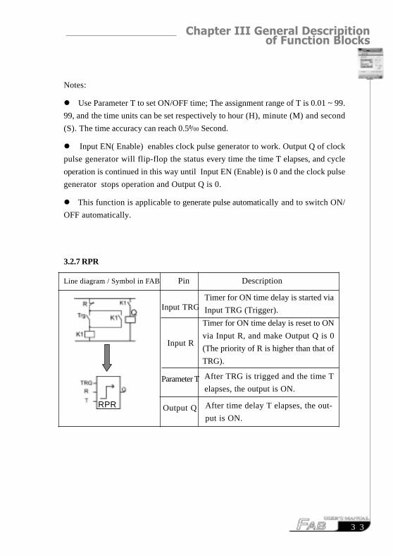
3.2.7 RPR
Line diagram / Symbol in FAB Pin Description
Input TRG
Input R
Parameter T
Output Q
Timer for ON time delay is started via
Input TRG (Trigger).
Timer for ON time delay is reset to ON
via Input R, and make Output Q is 0
(The priority of R is higher than that of
TRG).
After TRG is trigged and the time T
elapses, the output is ON.
After time delay T elapses, the out-
put is ON.
RPR

FAB Intelligent Controller
3 4
Note
� If the status of Input TRG changes from 0 to 1, the internal timer will be
activated. Whentime T is up, Output Q becomes 1 and then the input TRG coming
again has no effect on output Q .Only when Input R becomes 1 again Output Q and
Timer T will be reset to 0.
� This function is applicable to the locations where the time-delay ON and hold
ON status are required.
� The assignment range for T is 0.01 - 99.99, and the time units can be set
respectively to hour (H), minute (M) and second (S). Its time accuracy can reach
0.5 /00 Second.
Time Sequence Frame:
TRG
R
Q T T

Chapter III General Descripition of Function Blocks
3 5
3.2.8 UCN
Linediagram/symbol inFAB Pin Description
Time Sequence Frame:
Note: This function is applicable to the locations where counting is required.
R
Input CNT
Output Q
Input R has priority to other input,When
it inputs resetting signals, the counter is
reset to 0 and output Q is reset simulta-
neouslyWhen CNT counting is input, the counter
only counts the leading edge triggering (the
status changes from 0 to 1), i.e. every time
the leading edge is triggering, the counter
increase by 1.
When the internal counting value is greater
or equal to Parameter PAR, Output Q is
1. The assignment of counter is 0 ~ 999999.
When the counting value has been reached,
Output Q is On.
CNT
R
Q
Parameter
PAR

FAB Intelligent Controller
3 6
3.2.9 DCN
Linediagram/Symbol inFAB Pin Description
Note: This function is applicable to the locations where the counting is
required.
3.2.10 MPLR (Single-pulse time relay)
Pin Description
Input R
Input CNT
Output Q
R has a priority to other input,when R in-puts resetting signals,the counter is reset to0 and output Q is rest simultaneously
Trigger the input to activate the single-pulse time relay. When the leading edge ofTRG comes, a pulse with a duration of Tis output.
Reset the single-pulse time relay. When
R is 1, Output Q becomes 0.
The assignment of the pulse duration set-ting is 0.01 ~ 99.99 (second, minute, hour).
The time accuracy can reach 0.5 /00 Second.
Every time TRG changes from 0 to 1, Q
outputs a pulse with a duration of T.
Input
TRG
Input
R
Parameter
T
Output
Q
When CNT counting is input, the counteronly count the front edge triggering (thestatus changes from 0 to 1), i.e. every timethe leading edge is triggering, the counter isdecreased by 1.
When the internal parameter is decreased
to 0, Output Q is 1. The assignment of
counter is 0 ~ 999999.
When the counting value is 0, Output Q is
On.
Parameter
PAR
Line diagram/Symbol in FAB

Chapter III General Descripition of Function Blocks
3 7
Time Sequence Frame:
Note:
� When Q is 1, TRG pulse will have no effect on Output Q.
� This function is applicable to the locations where the pulse duration is required
to amplify.
3.2.11 Tel (it is necessary to purchase AF-MUL for use in combination) FAB
Figure Pin Description
TRG
R
Q T T T
The input port is selected as follows: I1 ~
IC, Q1 ~ Q8, HI, LO, M00 ~ M126, P0 ~
P9.
When output is 1, the telephone number of
output port will be dialed to output. If the
input has been 1 all the time, dialing will be
kept on,once every 30 seconds and when
the input is 0, dialing stops. The optionrange
of output port will not exceed 25-digit tele-
phone number.
Input
Output
FAB Intelligent Controller
3 8
Note:
� The functions of telephone block are mainly dialing, output, alarm, etc. This
block is used together with the locking-up relay (RS relay) function block . It can
be used to not only receive the coming call signals to control the terminal equipment,
but also dial to output the alarm under certain conditions. Presentation on how
to implement it is made as follows:
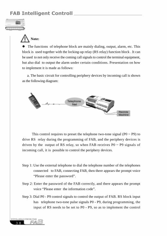
a. The basic circuit for controlling periphery devices by incoming call is shown
as the following diagram:
This control requires to preset the telephone two-tone signal (P0 ~ P9) to
drive RS relay during the programming of FAB, and the periphery devices is
driven by the output of RS relay, so when FAB receives P0 ~ P9 signals of
incoming call, it is possible to control the periphery devices.
Step 1: Use the external telephone to dial the telephone number of the telephones
connected to FAB, connecting FAB, then there appears the prompt voice
“Please enter the password”.
Step 2: Enter the password of the FAB correctly, and there appears the prompt
voice “Please enter the information code”.
Step 3: Dial P0 - P9 control signals to control the output of FAB. RS block input
has telephone two-tone pulse signals P0 - P9, during programming, the
input of RS needs to be set to P0 - P9, so as to implement the control
Chapter III General Descripition of Function Blocks
3 9
After the telephone lines and power supply lines of FAB and AF-MUL are
connected, dial the number of the telephone that is connected with FAB. When you
have got through, you will hear “Please input password”. Now input the password
for programming through the telephone number keyboard and please don’t forget
to start with “*” . After the password is properly inputted, please input “*” and
“0”. You will hear the prompt voice “Electrical appliance is switched on” and relay
Q1 will be on at the same time. If “*” and “9” are inputted, you will hear “Electrical
appliance is switched off” and relay Q1 will be off. The prompt voices for switch-
on and switch-off will continue for 5 seconds.
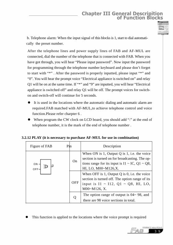
When ON is 1, Output Q is 1, i.e. the voicesection is turned on for broadcasting. The op-tions range for its input is I1 ~ IC, Q1 ~ Q8,HI, LO, M00~M126,X.
When OFF is 1, Output Q is 0, i.e. the voicesection is turned off. The option range of itsinput is I1 ~ I12, Q1 ~ Q8, HI, LO,M00~M126, X.
The option range of output is 04~ 98, and
there are 98 voice sections in total.
On
OFF
Q
� It is used in the locations where the automatic dialing and automatic alarm are
required.FAB matched with AF-MUL,to achieve telephone control and voice
function.Please refer charpter 6 .
� When program the CW clock on LCD board, you should add “:” at the end of
telephone number, it is the mark of the end of telephone number .
b. Telephone alarm: When the input signal of this blocks is 1, start to dial automati-
cally the preset number.
3.2.12 PLAY (it is necessary to purchase AF-MUL for use in combination)
Figure of FAB Pin Description
� This function is applied to the locations where the voice prompt is required

FAB Intelligent Controller
4 0
3.2.13 MR (it is necessary to purchase AF-MUL for use in combination)
Figure of FAB Pin Description
The options for the output port are 01 ~
09. Please note that: when the output is
selected as 99, it does not represent to
record the 99th voice section but that to
clear all the voice sections, therefore, care
should be taken for using .
When OFF is 1, recording is completed, turn
off the switch for recording voice sections.
The option range of this input is I1 ~ IC, Q1
~ Q8, HI, LO, M00~M126, X.
When ON is 1, record the voice sections.
The option range of the input is I1 - IC,
Q1 - Q8, HI, LO, M00~M126, X. ON
OFF
Q
Notes:
Please refer to charpter 6.to learn how to record your voice.
When making recording, recording should be performed in an order of 01 - 98 and
it is not allowed to be interrupted in the process, that is to say, it is not allowed to
record the third section after the first section is recorded. (If the same block is used,
the sections can be accumulated automatically as long as the conditions change) e.
g. I1 - ON, I2 - OFF and Q=01, the first section is input at the beginning when I1
is ON and I2 is OFF. When I1 is Off and I2 is ON, the first section is turned off.

Chapter III General Descripition of Function Blocks
4 1
3.2.14 General Analog Comparator
Figurein FAB pin notes in FAB
Note:
Only AF-10MR-D, AF-10MT-D, AF-20MR-D, AF-20MT-D type FABs have
this function.
� This function is used in the input block for analog quantity.
Operation of AN block
The comparison function of AN block is comparison between input1 and input3.
Such as when you select input2 as“ >”,it means that when input1>input3,Q will
be “0”,when input1<input3,Q will be “1”
Example1 : Input 1 =I1 Input 3=050 Input 2=“ >”, Q=Q1
If I1>5.0V,then Q1will be ON
If I1<5.0V, then Q1 will be OFF
Example 2: Input 1=I1 Input3=I2 Input 2=“ < ” ,Output=Q2
If I1<I2, then Q2 will be ON
If I1>I2 , then Q2 will be OFF.
comparative input port 1, with 0.0~10.
0, I1~IC to be selected.
comparative input port 2, with 0.0~10.
0, I1~IC to be selected.
with conditions available, output Q is 1
and its selection range is Q1~Q8,
M00~M126. Remarks: It may be com-
pared with “<=,>=,< , >, = ,=, ”.
Input 1
Input 2
Input 3
OutputQ
OutputQ
Function selection <=,>=,>,<,=,=
AN
Input1
Input2
Input3

FAB Intelligent Controller
4 2
RESUMERESUME

Chapter IV Programming operation on FAB panel
4 3
Chapter IV Programming operation on FAB panel
There are two methods of programming for FAB, one is to complete editing
of the function diagram directly on the operation LCD board using the keys,
while the other is to do the same on the computer using the programming soft-
ware QUICK II . Programming for FAB can be completed with either of the two
methods. This Chapter will describe in detail how to use the operation LCD
board to edit the Function Block Diagram Program and the programming method
using QUICK II will be covered in detail in the second part of this manual.
As shown in the following figure, the operation LCD board is a simple man-
machine interface and the program editing operation will be completed through
the 8 keys on the right: , , , , , , , .
The following rules shall be observed for programming operation on this panel:
1. When the cursor appears as an under line, it may be moved:
� Move the cursor along the lines with �, �, � and � keys;
� Press “OK” key to confirm selection of the input/output connection or the
function block;
� Press “ESC” key to exit the programming input.
2. When the cursor appears as >, the input/output or function block may be
selected:
� Select the input/output or function block with �and � keys;
� Press “OK” key to confirm the selection;
� Press “ESC” key to return to the previous step.

FAB Intelligent Controller
4 4
4.1 Display FAB of status
Connect the power line of FAB with the method as described in Chapter II. After
power is on, LCD displays a frame , which is the Switch-on Frame.
As shown in Fig of FAB. 4.2 (10 points type):
the upper line I contains the status values of input 1 ~ 6
the lower line Q contains the status values of output 1 ~ 4
(in which “*” indicates ON, i.e. status “1”; “ ” indicates OFF, i.e. status “0”.)
Fig. 4.2 Status Display Frame
4.2 Confirm password
By pressing ESC and OK simultaneously at the Status Display Frame as shown
in Fig. 4.2, it can enter the Confirm Password Frame, as shown in Fig. 4.3. Now it
is required by FAB to input the password value. Now the cursor stays at the
highest digit of the password, where you can change the digit value (0~9) with “-
” and “+” keys (when you initially press “-” or “+” key, the password value is 0).
I:
SA
Q: *
12:26:58
Fig. 4.1

Chapter IV Programming operation on FAB panel
4 5
Then you can use “ ” and “ ” keys to change the password input position and
input the password values of the remained digits . If a proper password is input, It
will enter the Edition Frame shown in Fig4.4. If the password is incorrectly input
consecutively twice, the Status Display Frame shown in Fig. 4.2 will be returned
to.
Note: The ex-works password is 0001.
Fig. 4.3 Confirm Password Frame
4.3 Funcation
While in the edition frame shown in Fig4.4, the user may use “ ” and “ ” keys to
move the arrow “>” on the left and press OK key to select the functions, with the
following 4 options for selection:
Editor: edit program; Edition Function Selecting Frame shown in Fig. 4.5 will be on
when this function is selected;
FAB/Rom: read program, modify the address and reset the modem,etc. The frame
shown in Fig4.19 will be on when this funcation is seleted.
Set.. : setup RTC real time clock and password;
RUN: start running FAB program.
Fig 4.4
Verify
Users
Password:
XXXX
>Editor
FAB/Rom
Set..
RUN

FAB Intelligent Controller
4 6
Fig. 4.5 Edition-function Selecting Frame
4.3.1.1 Edit PRG (Edit Function Block)
The Edit PRG Menu Frame is shown in Fig. 4.6 and the function blocks are to
be selected under this menu.
� Select Function Blocks:
The user may use “ ” and “ ” keys to move the arrow “>” on the left to select
the function blocks. Press OK key to select a function block, the Function Block
Setting Frame shown in Fig. 4.7 will be on (please refer to Chapter III Specifica-
tion of function Blocks). This menu includes the following function blocks:AND,
NAND, OR, NOR, XOR, NOT, RS, UCN, DCN, PLR, MPLR, CPG, RPR, DPR,
DDR, CW, TEL, PLAY, MR,ANALOG (D type).
>Edit Prg
Insert FB
Delete FB
Clear Prg
4.3.1 Editor (edit program)
When this function key is selected, FAB will enter the Edition Function Selecting
Frame shown in Fig. 4.5. The user may use “ ” and “ ” keys to move the arrow
“>” on the left and press OK key to select the functions.
Edit PRG: Input a function block (consult 4.2.1.1);
Insert FB: Insert a function block into the existing program (consult 4.2.1.2);
Delete FB: Delete a function block from the existing program (consult 4.2.1.3);
Clear PRG: Delete all program blocks.

Chapter IV Programming operation on FAB panel
4 7
Fig. 4.6 Function-Selecting Frame
� Set Function Block:
When Input Function Block is selected, FAB will automatically help you to
define in sequence the numbers of the blocks beginning with “B” and display the
said numbers in the bottom right corner (e.g. B01), as shown in Fig. 4.7.
The user may select the input/output and parameter values set for the function
block by moving “ ”, “ ”, “ ”, “ ” keys (please refer to Chapter III
Specification of Function Block for the input/output/parameter values for differ-
ent function blocks).
When Selection Output/Input Pin is set, press OK key to enter Parameter Setting
Status. The user may use “ ”, “ ” keys to select the connection point type and
operand for the said output/input, as shown in the top left corner in Fig. 4.7. First
move the cursor to “I” in the top left corner with “ ”, “ ” keys, change the type
of the connection point with “-” and “+” keys and press OK to confirm it. Then
increase or decrease the operand for the connection point with “-” and “+” keys
(e.g. I0, I1, I2, etc.).
Note: The operands for different types of connection points have different
ranges. It is I1 ~ I6 (10 point type) or I1~IC (20 point type)for I (input) and
Q1 ~ Q4 (10 point type)or Q1~Q8(20-point type)for Q (output). Operands
are not required for H (high protential status), L (low protential status) and
X (empty). M means intermediate relays M00 ~ M99.
>AND
NAND
OR
NOR
NOT
XOR

FAB Intelligent Controller
4 8
Fig. 4.7 Setting the parameter of function blocks
Described above are the setup of basic function blocks. It is also necessary to
explain setup of the operands for some special function blocks in the following.
1. Function blocks with timing function
Function blocks with timers include:
DPR: Delay putting Relay CPG: Clock Pulse Generator
DDR: Delay Disconnection Relay RPR: Retentive On Relay
MPLR: Single-pulse Relay CW: Clock Switch
PLR: Pulse Relay
When parameter T is set, the following frame will be on LCD:
Fig. 4.8
Line 1: Block number and timing mark
Line2: time units-- HOU(Hour) , MIN(Minute),SEC(second)
Line3: Setting integer of time (00-99)
Line 4: Setting decimal of time(00-99)
&
B01
I0
B02: Time
00: Unit
00: Int
00: m

Chapter IV Programming operation on FAB panel
4 9
2. Lunction blocks with counting function include:
UCN: Up Counter
DCN: Down Counter.
When the PAR is set, the following frame will be on the LCD:
Fig. 4.9
The 1st line represents the block number and counter mark
The 2nd line represents the highest digit of the counting value
The 3rd line represents the second-highest digit
The 4th line represents the lowest digit.
You may set the parameters in turn, as required, by pressing and to
move the cursor and select the parameters and pressing and to change
the value.
For example,for setting a number as 967843. D1=96,D2=78,D3=43.
3. Set parameters for the Clock Switch
1) As the date system D is selected, the following will be on LCD:
Fig. 4.10
Day
D 2000,00,00
T1 000000
T2 000000
B01: Count
00: D1
00: D2
00: D3

FAB Intelligent Controller
5 0
The 1st line represents the date system
The 2nd line represents year, month and day
The 3rd line represents the output ON time(T1).
The 4th line represents the output OFF time(T2).
2) As the week system W is selected, the following will be on LCD:
Fig. 4.11
At this time , you can use “+”,“-” keys to select the type of weeks.
MO represents Monday
TU represents Tuesday
WE represents Wednesday
TH represents Thursday
FR represents Friday
SA represents Saturday
SU represents Sunday
MO-TH represents Monday to Thursday
MO-FR represents Monday to Friday
MO-SA represents Monday to Saturday
MO-SU represents Monday to Sunday
FR-SU represents Friday to Sunday
SA-SU represents Saturday to Sunday.
Week
00 SU

Chapter IV Programming operation on FAB panel
5 1
After selecting the week system.press the ESC key,you will be able to select the
timing and the following will be on LCD:
Fig. 4.12
The first line represents the week system
The second line represents year, month and day
The third line represents the output-ON time
The forth line represents the output-OFF time.
You only need set T1,T2,and needn’t set D when you select the week system
The set date will be neglected by the system
4. Set the Telephone Block
When the Telephone Block is selected, the following will be on LCD. Set the input
on the left of the block first, move the cursor to the output on the right and press
OK key.
Fig. 4.13
Week
D 2000,00,00
T1 000000
T2 000000

FAB Intelligent Controller
5 2
After OK key is pressed, the following will be on LCD:
Fig. 4.14
Press , , , keys to move the cursor and select the digit of the
telephone which is up to 25-digit number and press , to change the value
and set digit of the telephone number in turn. After the number is set, move the
cursor to the last digit of the set number and press to exit .
when you complete setting the telephone number,you must add a “:”
marking the end of the mumber.
Phone Code
0000000000
0000000000
00000
5. Set the AN block
AN block is as follows
Input 1: I and K are available input.
(1) That I is selected represents this port is connected to FAB’s input, whose
range is “I1~I6”(AF-10 series), and “I1~IC”(AF-20 series). The input opera-
tion on the LCD board is the same as general. That K is select represents the
digital value, whose range is “000~100”, which represents voltage “0~10.0V”.
The pre-two digits represent integer, and the last digit represents decimal.
Input1
Input2
Input3

Chapter IV Programming operation on FAB panel
5 3
(2)When input 1 is “K”or “I”,press “ok” to confirm and then press”+” and “-” to
change the digital value .Finally press “OK” to confirm.
Input 2: It represents function selection, There are 5 comparison functions which can
be selected “>, <, <=, >=, = ”. Selecting by using “ , ” ,and then press
“OK”to confirm.
Input 3: It is the same as Input 1.
4.3.1.2 Insert FB
This function can be used to insert a function block into a scheduled block position.
The operating process is as follows:
1. Press OK at “>Insert FB” in the Editor Frame,thus the inserting status is
entered, as shown in Fig. 4.15.
Fig. 4.15 Insert Function Block
2. 000 shown in the above frame is the original value. Press “+”, “-” to select block
number and then press “OK” to confirm. The range of inserted block number is
from 001 to the maximum number of current program If the selected number is
not in this range, it will be no effect to press “OK” and it will return to the
origiral status to let you select block number in suitable range .If you want to
give up to inserting a block,please press”ESC” to exit. If you are not clear about
the maximum number in the programm ,you can use ROM-FAB in FAB/ROM
to read the program and get the number.
3 If you select a right number in the above step and press “OK” key to confirm,
then machine will affect your operation and function block codes menu(eg.
AND,OR,NOT,RS,TEL,...etc.)will appear for you to select.
Insert:
000

FAB Intelligent Controller
5 4
4.3.1.3 Delete FB
This function can be used to delete any function block. The operating process is as
follows:
1. Press “OK” at “>Delete FB” in the Editor Frame ,thus the deleting status is
entered, as shown in Fig. 4.16.
Fig. 4.16 Delete Function Block
2. 000 shown in the above frame is the original value.Press “+” and “-” to select
block No.and then press “OK”. The range of block number for Delete FB is
from 001 to the maxmum number of current program. If the selected number is
not in this range, it will be no effect to press”OK” and it will return to the
orginal status to let you select block No.in suitable range. If you want to give
up to deleteing operation,please press”ESC” to exit.If you are not clear about
the maximum number in the programm, you can use FAB-ROM in FAB/
Rom to read the program and get the number.
3.If you have select a correct block number , press “ OK”, FAB will display as
follows.It means the selected block has been deleted.
Note:If you do not go on selecting but exit,FAB will copy a function block of
the same block number in the machine. But if you are in edition step,
you can exit only when you finish setting all of the terminals. And then
you can delete the block by using Delete FB.
Delete:
000
Chapter IV Programming operation on FAB panel
5 5
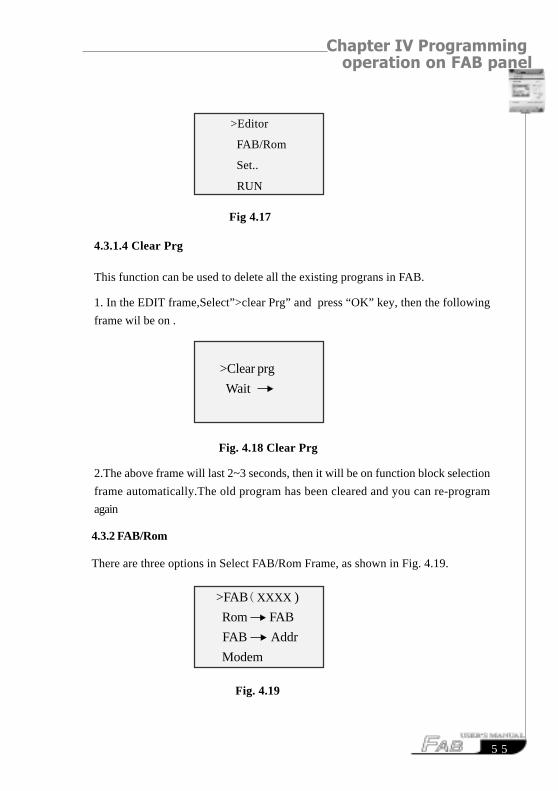
4.3.2 FAB/Rom
There are three options in Select FAB/Rom Frame, as shown in Fig. 4.19.
Fig. 4.19
>FAB( XXXX )
Rom FAB
FAB Addr
Modem
This function can be used to delete all the existing prograns in FAB.
1. In the EDIT frame,Select”>clear Prg” and press “OK” key, then the following
frame wil be on .
Fig. 4.18 Clear Prg
2.The above frame will last 2~3 seconds, then it will be on function block selection
frame automatically.The old program has been cleared and you can re-program
again
>Clear prg
Wait
>Editor
FAB/Rom
Set..
RUN
Fig 4.17
4.3.1.4 Clear Prg

FAB Intelligent Controller
5 6
4.3.3 SET (set password and time)
The SET Frame is shown in Fig. 4.20. A password and real time clock can be set
for the edited FAB function program via this SET Frame. When you want to modify
the control function, the said password shall be properly input before the edition
modification status can be entered (note: the ex-factory password of FAB is 0001).
This function is the password lock function of FAB.
Fig. 4.21 Set Password Frame
Set Real Time Clock (hour:miniute:second)
Set Date (year:month:date)
Set Weekday
Set password
FAB(XXXX): (The serial No.of FAB system service)(Not to be used.)
Rom FAB: read the program from FAB
FAB-Addr: view or modify FAB address
MODEM: initialize MODEM.
4.3.2..1- Read program from FAB(Rom FAB)
1.Select “Rom FAB”in FAB/ROM and press “OK”, the following frame will be
on.
Fig. 4.20
2.press “ ” in the state shown in Fig 4.20,then the program will be read block
Rom FAB
Wait
10:49:04
2000/06/21
Day SU
5678
Chapter IV Programming operation on FAB panel
5 7
4.4 Edit FAB function program
During editing of FAB function program, special attention need be paid to some
programming rules,the application of the intermediate relays and how to use FAB’s
operation key panel with LCD to edit the FAB function program.
4.4.1 Programming rules
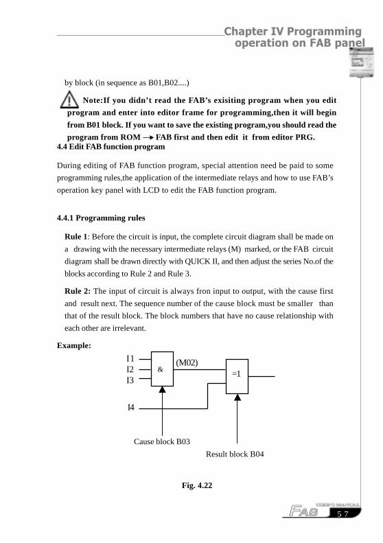
Rule 1: Before the circuit is input, the complete circuit diagram shall be made on
a drawing with the necessary intermediate relays (M) marked, or the FAB circuit
diagram shall be drawn directly with QUICK II, and then adjust the series No.of the
blocks according to Rule 2 and Rule 3.
Rule 2: The input of circuit is always fron input to output, with the cause first
and result next. The sequence number of the cause block must be smaller than
that of the result block. The block numbers that have no cause relationship with
each other are irrelevant.
Example:
Fig. 4.22
by block (in sequence as B01,B02....)
Note:If you didn’t read the FAB’s exisiting program when you edit
program and enter into editor frame for programming,then it will begin
from B01 block. If you want to save the existing program,you should read the
program from ROM FAB first and then edit it from editor PRG.
Cause block B03
Result block B04
I1 I2 I3
=1
I4
(M02)
&

FAB Intelligent Controller
5 8
Rule 3: In a program path, output may be connected to the lead input (for
number transfer), but the block with a smaller sequence number shall be used as the
lead input (cause block) and the one with a larger sequence number shall be the result
block. If the user desires for contrary cause and result blocks, he needs only to
adjust the block sequence numbers.
Rule 4: One output terminal may be connected to multiple input, but multiple
output may not be connected to one input terminal.
Rule 5: At power-on and initialization of FAB (at the instant of power-on), the
intermediate relay (M) and output port (Q) are all in logical 0 status. Their later
status will be determined by the program.
Rule 6: It will be not all owed to connect two output terminals with one end as
follows.
& M00
The above is prohibited except in CW block
4.4.2 Intermediate relay
In FAB programming ,the intermediate relay is a very important bridge. The interme-
diate relay of FAB is similar to that in the relay control system. They can store some
intermediate status and then transfer it to a block requiring the status for input. Using
of intermediate relays has two advantages:
1. The output terminal of the previous block can be used as the input terminals for
different blocks;
2. When a block is inserted or deleted, the original logical relation can be retained.
No intermediate relay is provided for other products of the same category. The basic
functions of the intermediate relay are shown in the following figure:
B01
B02
& M00 I3
I4
I1
I2

Chapter IV Programming operation on FAB panel
5 9
Fig. 4.23
In the above figure, the output status of B01 may not only be used directly as the
input of B02 block, but also be stored by M01 and then used as the input of B03.
4.4.3 Edit program
Take the stair lighting system for example, with the following control requirements:
1. When the switch button is pressed, the light will be turned on and kept normally on;
2. When the sound sensed switch is on, the light will be turned on and kept on for
2 minutes.
The Function Block Diagram for the said control function is as follows:
Fig. 4.24
The following procedure shall be followed for editing of the said control function
with FAB operation panel:
In case a user program already exists in FAB:
I1
I2
B01
M01
B02B03
M02M01
I3I4 I5 Q1
I1 shall be connected to switch off buttonI2 to switch on buttonI3 to sound controlled switch
B1
B2
M1Q1
M2
TimeOut=2.00minf
B3I2
I1
I3
M1X
M2
XT
I1I2

FAB Intelligent Controller
6 0
Step I: Enter FAB Editor Frame
1. In 2 ~ 3 seconds after switch-on, the following will be on LCD:
Fig. 4.25
2. After and are pressed simultaneously, the Confirm Password Frame is
entered,At this time the cursor will stay at the highest digit of the password and the
following will be displayed on LCD:
Fig. 4.26
3. Input the password, with the password assumed as 2165;
� Press twice and the first digit value of the password will change to 2;
� Press right moving key and the cursor will move one digit to the right for the
second digit of the password value to be input;
� Press once and the second digit of the password value will become 1;
� Press and the cursor will move one digit to the right for the third digit of the
password value to be input;
� Press 6 times and the third digit of the password value will become 6;
Verify
Users
Password:
XXXX
I:
SA
Q: *
12:26:58

Chapter IV Programming operation on FAB panel
6 1
� Press and the cursor will move one digit to the right for the last digit of
the password value to be input;
� Press 5 times and the last digit of the password value will become 5.
After the password is completely input, the following will be on LCD:
Fig. 4.27
4. Press to enter the Edition Function Selection Frame, with the selection
mark “>” staying at Editor function. The following is on LCD:
Fig. 4.28
Step II: Edit Function Diagram
1. Press to select Editor and the Function Block Selection List is entered.
The following is on LCD:
2. Select and set the first function block:
Verify
Users
Password:
2165
>Editor
FAB/Rom
Set..
RUN

FAB Intelligent Controller
6 2
� move “>” to the position of RS relay with and press OK to enter the
Function Block Set Status, when the cursor will stay at the highest input pin.
The following will be on LCD:
Fig. 4.30
� Press and the Set Parameter R link input status will be entered. Now “I”
will appear at R pin. If you do not want to select “I”, you may press to
select “Q” and press it again to select “H” and may continue on till “M”. It means
that the user may select any parameter among I, Q, H, L, C, P and M by pressing
. After “I” is selected, the following will be on LCD:
Fig. 4.31
� Then it is necessary to set the parameters, namely to set the values with ,
>AND
NAND
OR
NOR
NOT
XOR
>RS
B01
R
S
B01
I1
s
Fig. 4.29

Chapter IV Programming operation on FAB panel
6 3
. For example, if I1 is to be set, just press key when I1 is displayed,
as shown in Fig. 4.31 (the variation range of I is I1-I6 or I1-IC).
Fig. 4.32
� Press to move the cursor to position Q and press to set the Q pin output.
After selecting “M” in the parameter list and setting it to M01 with , ,
press again, the following will be displayed on LCD:
Fig. 4.33
Now, all the three links and edit the following blocks of the RS relay function block
are setThen press”ESC”to exit this block..
Note : When the FAB enter the edit function block, it can not exit to the 1-level
higher programming interface by pressing ESC key or OK key unless
you have set all the pins of this block (including all the I/O pins)
B01
B01
I1
I2
� Press to move the cursor to position S and press to set the S pin input.
Select “I” in the parameter list and set it to I2 by the same method as setting I1
and pressing once. The LCD will be as in Fig.4.32.

FAB Intelligent Controller
6 4
3. Select and set the second function block
� Press to return to the Function Block Selection List Frame and select the
second function block.
� Move ">" to the position of DDR function block and press .Now you can
set the parameters for the function block. The following will be on LCD:
Fig. 4.34
� Press to enter Set Trg Pin Parameter Status. Select “I” in the parameter list
with “ , ” and press . Then set Trg to I3 with “ , ”. The
following will be displayed on LCD:
Fig. 4.35
� Press to move the cursor to position R and press to set the r input
parameter . After selecting “X” in the parameter list, press to set the
parameter X. The following will be displayed on LCD:
B02
I3rt
B02

Chapter IV Programming operation on FAB panel
6 5
Fig. 4.36
� Press to move the cursor to position T and press to enter the Set Timer
Frame. The following will be displayed on LCD:
Fig. 4.37
� Press to enter the Time Unit Selection Status. Now the options can be
changed with , . When “min” appears, press to set the time unit
as minute. The following will be displayed on LCD:
Fig. 4.38
� Press to set the integer of the time and use , to change the value.
Set it as 02.
� Press to set the decimal of the time and use , to change the value.
Set it as 00.Now the time is set to 2 minutes.Press “OK”,and the press”ESC”to
exit
B02: Time
Hou: Unit
02: Int
00: m
B02: Time
Min: Unit
02: Int
00: m
B02

FAB Intelligent Controller
6 6
� Press to move the cursor to position Q, press . Set Q as M02 and then
press again. The following will be on LCD:
Fig. 4.39
4. Select and setup the third function block
Press to return to the Function Block Selection List Frame and select the
third function block.
Move “>” to the position of OR function block and press . Now you can set
the parameters for the third function block. The following will be displayed on
LCD:
Fig. 4.40
� Press to enter the first input parameter set status. Select parameter M with
, and set the parameter value with , . When M01 appears,
press and the first parameter will be set to M1. The following will be on LCD:
B02
M02
B03

Chapter IV Programming operation on FAB panel
6 7
Fig. 4.41
� Press to move the cursor to the second input parameter and press .
Now the second input parameter can be set. After selecting X with , and
pressing , the said input is set to X. The following will be displayed on LCD:
Fig. 4.42
� Move the cursor to the third input pin and press .
� After selecting M in the parameter list, press and set the said input to M2
with , . The following will be on LCD:
Fig. 4.43
M01
B03
M01
X
M02B03
M01
X
B03

FAB Intelligent Controller
6 8
>Editor
FAB/Rom
Set..
RUN
� Move the cursor to the output pin with and press ;
� After selecting Q in the parameter list, press and set the said output pin as
Q1 with , . The following will be displayed on LCD:
Fig. 4.44
Now all the three function blocks required for editing of this function diagram are
selected and set , which means that the Function Diagram is completely edited.
Step III: Run
1. After Step II is finished, press twice consecutively to return to the Select
Function Selection. The following will be displayed on LCD:
Fig. 4.45
2. Move “>” to RUN and press . The following will be on LCD:
M01
X
M02
Q1
B03

Chapter IV Programming operation on FAB panel
6 9
* * * *
*
Fig. 4.46
3. It means that program is written into FAB and begin to runauording to the new
program.
Note: How to read and modify the current program.
1.Press ESC and OKsimultaneously to enter the password frame, and then enter
the correct password, and then press “OK’.
2. Select “FAB/ROM”, and press “ OK”.
3.Select “ ROM FAB”, and then press “OK”.
4. Press and to select and read the function block, and press OK to confirm
and make the modification.
RESUMERESUME
SA

FAB Intelligent Controller
7 0
RESUMERESUME

Chapter V Remote programming and monitoring
7 1
connected
to FAB
1
2
3
4
5
67
896
78
9
12
34
5
Chapter V Remote programming and monitoring
5.1 Remote programming and monitoring via MODEM
FAB can realize ultra-remote programming and monitoring function through
MODEM. If you need to program or monitor an FAB on a worksite kilometers
away or even between two cities, this function of FAB will just satisfy your
requirement.
After the connection of FAB, AF-C232 (or AF-MUL), AF-M232 and MO-
DEM (refer to 5.2 for details of the connection diagram), switch on the power and
MODEM will automatically complete the initialization. If MODEM is not
initialized, you may press OK on the MODEM menu under FAB/ROM of LCD
programming interface to initialize it.
Connect the MODEM to a PC provided with QUICK II or FAB-SCADA and
make connection with FAB by dialing the telephone number connected to FAB
through the PC. Now remote programming and monitoring can be carried out.
Note:You may buy our company’s AF-M232 product or make it by yourself.
AF-M232 is a standard DB9 DB9 connection.
The Cable Connection Diagram for AF-M232 is as follows:
connected to
MODEM

FAB Intelligent Controller
7 2
5.2 Two connection methods for FAB remote programming and monitoring
5.2.1 Connect MODEM by means of AF-C232 and AF-M232
For connecting with this method, you need to purchase the following parts: AF-
C232, AF-M232. The connection diagram is as follows:
5.2.2 Connect MODEM by means of AF-MUL
If you have purchased the telephone voice multi-function block, it is not necessary
to have AF-C232. The connection diagram is as follows:

Chapter VI Voice Module
7 3
chapter VI Voice Module
1 2
3 4
5
6
8
7
9
Voice alarm function, telephone control function and dialing automatically
function are very important functions of FAB. To realize these functions, we
should match FAB with voice module AF-MUL.
6.1 The structure of voice module:
Fig 6.1 Structure of AF-MUL
1. Socket of telephone crystal plug
2. Power terminals(110-240V)
3. Connecting Port with FAB
4. Power landicator
5. Recording lndicator
6. Recording Microphone
7. Volume Turning only control the volume of AF-MUL Speaker itself
8. Terminal for outside speaker(it can be connected to outside powered-
speaker to loud the voice and is not control by 7 Volume Turning
9. Communication Port:Connected with the computer to monitor or program
for FAB or Connected with MODEM via M232 to remote monitor FAB(the
same funtion with AF-C232).
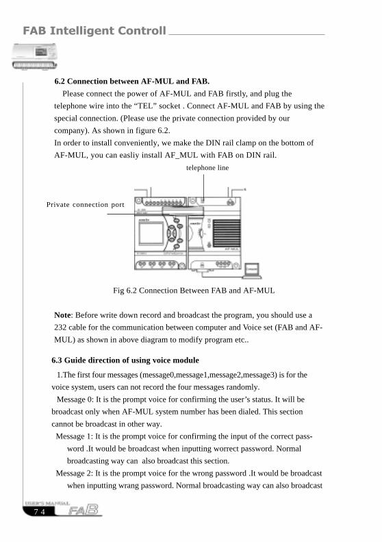
FAB Intelligent Controller
7 4
6.2 Connection between AF-MUL and FAB.
Please connect the power of AF-MUL and FAB firstly, and plug the
telephone wire into the “TEL” socket . Connect AF-MUL and FAB by using the
special connection. (Please use the private connection provided by our
company). As shown in figure 6.2.
In order to install conveniently, we make the DIN rail clamp on the bottom of
AF-MUL, you can easliy install AF_MUL with FAB on DIN rail.
telephone line
Private connection port
Fig 6.2 Connection Between FAB and AF-MUL
Note: Before write down record and broadcast the program, you should use a
232 cable for the communication between computer and Voice set (FAB and AF-
MUL) as shown in above diagram to modify program etc..
6.3 Guide direction of using voice module
1.The first four messages (message0,message1,message2,message3) is for the
voice system, users can not record the four messages randomly.
Message 0: It is the prompt voice for confirming the user’s status. It will be
broadcast only when AF-MUL system number has been dialed. This section
cannot be broadcast in other way.
Message 1: It is the prompt voice for confirming the input of the correct pass-
word .It would be broadcast when inputting worrect password. Normal
broadcasting way can also broadcast this section.
Message 2: It is the prompt voice for the wrong password .It would be broadcast
when inputting wrang password. Normal broadcasting way can also broadcast

Chapter VI Voice Module
7 5
this section.
Message 3: It is prompt voice for dialing outside connected telephone.It would be
broadcast when FAB dial outside connected telephone. Normal broadcasting
way can also broadcast this section.
2. The usage of the four special messages.
For example: users can use the four messages as follows.
(1) Record message 0 as “ Please enter the password for confirmation”
Record message 1 as “correct password, please do the next step”
Record message 2 as “ wrong password , please re-enter”
Record message 3 as “Alarm, please enter the password and carry out the
real time control.”
(2) When users dial the FAB system number, AF-MUL will answer the telephone
automatically and broadcast “ please enter the password for confirmation”, then
users enter the password.
A. If the entered password is correct, FAB system will broadcast “correct
password, please do the next step ”, then users can control the equipment by
telephone.
B. If the entered password is not correct, FAB system will broadcast “wrong
password , please re-enter”, and then FAB system will broadcast message 0
repeatedly.
(3) When FAB voice system dial some pre-set telephone number, it will broadcast
the pre-set message such as message 4 “Gas leakage, alarm” together with
message 3 “Alarm, please enter the password to control”.
A. When users enter the correct password, the voice system will broadcasts
message 1 and then broadcasts message 4 repeatedly. At this time, users can
real-time control the equipment by telephone.
B. When users enter a wrong password, the voice system will broadcast
message 2, “wrong password, please re-enter”, and then the voice system
will broadcast message 3 and message 4 repeatedly.
Note:

FAB Intelligent Controller
7 6
A. When an outside connected telephone is dialed by FAB voice system, if there
is no answer or no inputting password after the answer in 40 seconds,the
FAB voice system will stop dialing and broadcasting the voice.Then it will
redial automatically every 20 seconds.
B. User must enter a “*” button before entering the password, Then the
broadcasting will stop and user should enter a four-digitals password in nine
seconds.If user fail to enter the password,it will re-broadcasting the prompt
voice.The user must enter “*” first and then enter the password, if he want
to enter the password again.That is to say ,every time the user input
passweord he must enter a “*”first and then a four-digitals password,in nine
seconds after the stop of the broadcasting.
C. When user finish entering the correct password, the voice system will
broadcast message 1“correct password, please do the next step.” And then
user can carry out the following operation. If the password is wrong, the
voice system will broadcast message 2 “ wrong password , please re-enter”.
Please well know that you can only enter wrong password twice, when you
enter the wrong for the third time, FAB will hang up the telephone and stop
broadcasting. Then it will return to the main system. If the alarm status is
still exist, the voice system will dial automatically for alarm every 20
seconds.
D. When the alarm voice is exist, FAB will broadcast the alarm voice repeatedly
every 20 seconds, it will stop by using anti-control function of the program.
E. After FAB’s dialing ,if the user don’t switch-off the alarm ON/OFF switch
via anti-control(ie., the alarm status is not clear up),FAB will dial to alarm
automatically every 20 seconds.
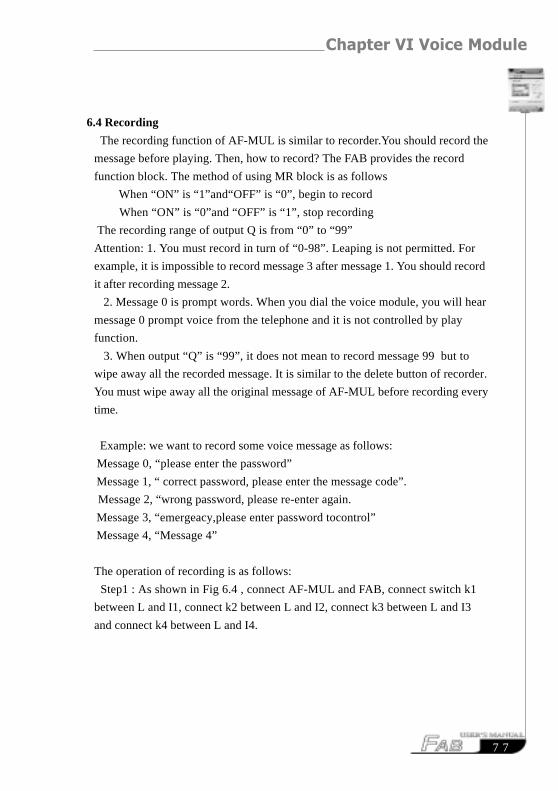
Chapter VI Voice Module
7 7
6.4 Recording
The recording function of AF-MUL is similar to recorder.You should record the
message before playing. Then, how to record? The FAB provides the record
function block. The method of using MR block is as follows
When “ON” is “1”and“OFF” is “0”, begin to record
When “ON” is “0”and “OFF” is “1”, stop recording
The recording range of output Q is from “0” to “99”
Attention: 1. You must record in turn of “0-98”. Leaping is not permitted. For
example, it is impossible to record message 3 after message 1. You should record
it after recording message 2.
2. Message 0 is prompt words. When you dial the voice module, you will hear
message 0 prompt voice from the telephone and it is not controlled by play
function.
3. When output “Q” is “99”, it does not mean to record message 99 but to
wipe away all the recorded message. It is similar to the delete button of recorder.
You must wipe away all the original message of AF-MUL before recording every
time.
Example: we want to record some voice message as follows:
Message 0, “please enter the password”
Message 1, “ correct password, please enter the message code”.
Message 2, “wrong password, please re-enter again.
Message 3, “emergeacy,please enter password tocontrol”
Message 4, “Message 4”
The operation of recording is as follows:
Step1 : As shown in Fig 6.4 , connect AF-MUL and FAB, connect switch k1
between L and I1, connect k2 between L and I2, connect k3 between L and I3
and connect k4 between L and I4.
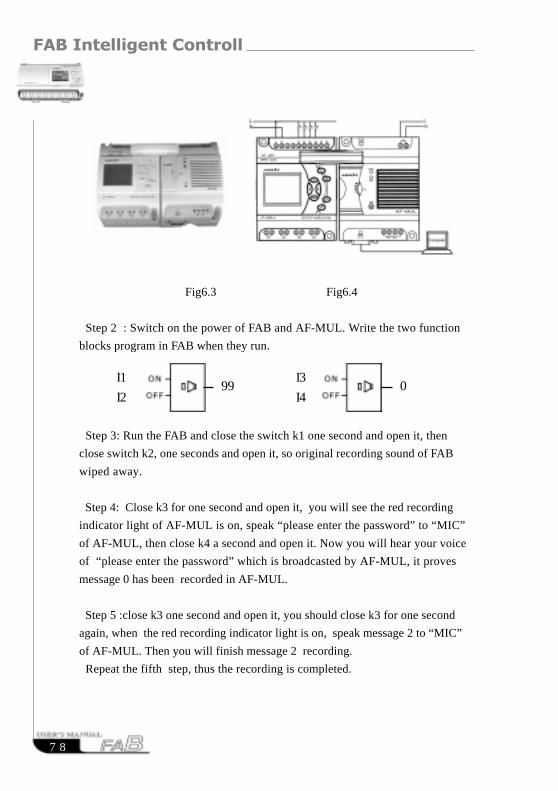
FAB Intelligent Controller
7 8
Fig6.3 Fig6.4
Step 2 : Switch on the power of FAB and AF-MUL. Write the two function
blocks program in FAB when they run.
Step 3: Run the FAB and close the switch k1 one second and open it, then
close switch k2, one seconds and open it, so original recording sound of FAB
wiped away.
Step 4: Close k3 for one second and open it, you will see the red recording
indicator light of AF-MUL is on, speak “please enter the password” to “MIC”
of AF-MUL, then close k4 a second and open it. Now you will hear your voice
of “please enter the password” which is broadcasted by AF-MUL, it proves
message 0 has been recorded in AF-MUL.
Step 5 :close k3 one second and open it, you should close k3 for one second
again, when the red recording indicator light is on, speak message 2 to “MIC”
of AF-MUL. Then you will finish message 2 recording.
Repeat the fifth step, thus the recording is completed.
I1
I2
I3
I499 0

Chapter VI Voice Module
7 9
When program was written into the FAB, and the FAB run, turn on the
switch K1 for a second then turn off. At this time you will hear “Message 4” ,
and then turn on the switch K2 for a second then turn off, the broadcast will
be closed.
Turn on the switch K3 for a second and turn off, you will hear “message 8”
you recorded voice. Turn on the switch K4 and then turn off, the sound will
be closed.
Notes: If the two broadcasting function blocks are both action, it will
broadcast the function block with bigger number, which is the principle “later-
command superior to the former”.
6.6 Telephone remote Control Function
If you want to control the distant equipment by mobile phone or common
telephone, you should connect FAB to AF-MUL, as shown in figure 6.2.
Because FAB have RS block which can be driven by the double tone information.
Signal (P0-P9), you only need to write the program with RS block in FABand it
will work.
For example, if you want to let the P3 button control the Q2 of FAB, you
should write the following program into FAB beforehand. The AF-MUL
broadcast firstly is prompt voice (that is message 0 you recorded.)when you dial
the telephone No.connected to AF-MUL
RS Q
6.5 Sound Broadcasting
Write the sound playing FB into the FAB, and set up the property. Set up
the relevant broadcasting voice section: message 4 and message 8, as follows:
I1
I2
I3
I404 08
X
P3
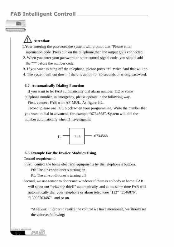
FAB Intelligent Controller
8 0
Attention:
1.Your entering the password,the system will prompt that “Please enter
inprmation code .Press “3” on the telephiine,then the output Q2is connected
2. When you enter your password or other control signal code, you should add
the “*” before the number code.
3. If you want to hung off the telephone, please press “#” twice.And that will do
4. The system will cut down if there is action for 30 seconds or wrong password.
6.7 Automatically Dialing Function
If you want to let FAB automatically dial alarm number, 112 or some
telephone number, in emergency, please operate in the following way.
First, connect FAB with AF-MUL. As figure 6.2.
Second, please use TEL block when your programming. Write the number that
you want to dial in advanced, for example “6734568”. System will dial the
number automatically when I1 have signals:
6.8 Example For the Invoice Modules Using
Control rerquirenent:
First, control the home electrical equipments by the telephone’s buttons.
P0: The air-conditioner’s turning on
P1: The air-conditioner’s turning off
Second, we use sensor to doors and windows if there is no body at home. FAB
will shout out “seize the thief!” automatically, and at the same time FAB will
automatically dial your telephone or alarm telephone “112” “3546876”,
“13905763487” and so on.
*Analysis: In order to realize the control we have mentioned, we should set
the voice as following:
TELI1 6734568

Chapter VI Voice Module
8 1
0: Please enter password.
1: Correct password,please enter control information code.
2: Wrong password. Please enter again.
4: Emergency,please enter the password and control message.
5: Turn on the air-condition.
6: Turn off the air-condition.
The first step: refer to section 6.3, record the above six sections voice.
The second step: connect I0 with the doors and windows’ sensor.
The third step: edit program as follows.
Dialing the number which AF-MUL connect with after finishing the connection
and installation of FAB and AF-MUL, recording and producing the invoice and
writing the program. You will hear the word “please enter password”, you would
(the fifth
section voice£)
P1
P0
B1
B3
B03
B5
B10
B9(M1)
5.0s
M5
3545876
1
1
Q 1
RS
RS
B4
B14 B13
B6
B2
B11B12
B15B16
B7 B8
M0
M3
M11
M2
M8M9
M4M6
M12
M10
L0
P9
t=1s
t=1s
t = 3 s
I1
t=3s
t=1s
t=1s
t=3s
(the forth
section voice£)D P R
D P R
MPLR
R P RT E L
D P R
MPLR
1
1 >
FAB Intelligent Controller
8 2
enter the correct password. You should pay attention to enter the “*” first .Then
you may hear “please enter the control information password, and enter “*,0”,
and you will hear “ turn on the air-condition ”, at the same time the air-
condition turn on. When you enter “*,1”, you will hear “Turn off the air-
condition” and at the same time you will see the air-condition is turned off.
Enter “*,3”, you will hear “turn on the hot water heater ”,and at the same time
the hot water heater is turned on. When you enter “*,4”, you will hear “ turn off
the hot water heater”, and at the same time it will be turned off. When you
switch on I1, you will hear “seize the thief”. And the telephone
number”354876” is dialed.
RESUMERESUME

Chapter VII Technical specifications
8 3
Chapter VII Technical specifications
7.1 General technical specifications
Item basis condition
Climate environment
ambient temperature cold: IEC68-2-1, hot: IEC68-2-2
Horizontal installation 0 ~ 55 C
vertical installation 0 ~ 55 C
Storage/transportation -40 C ~ +70 C
Relative humidity IEC68-2-30 5% ~ 95%,without condensation
Atmospheric pressure 795 ~ 1080kpa
Pollutants IEC68-2-42 H2Slcm3/m3, 4days
IEC68-2-43 SO210cm3/m3, 4days
Mechanical environment
protection type IP20
Vibration 2 IEC68-2-6 10 ~ 57Hz (constant amplitude 0.15mm)
57 ~ 150Hz (constant acceleration 2g)
Impact IEC68-2-27 18 impacts (semi sine 15g/11ms)
Fall IEC68-2-31 falling height 50mm
Freely falling body (with package) IEC68-2-32 1m
Electromagnetic compatibility (EMC)
Static discharge severe grade 3 8kv air discharge, 6kv contact discharge
Electromagnetic field IEC801-3 field strength 10V/m
Interference suppression EN55011 limitation grade B group 1
Shock pulse IEC801-4 2.2kV for power line
severe grade 3 2.2kV for signal line
IEC/VDE safety information
Insulation lIntensity IEC1131 meeting the requirement

FAB Intelligent Controller
8 4
7.2 AF-10MR-A / AF-20MR-A
Power Supply AF-10MR-A AF-20MR-A
Allowable range of 8 input voltage rating 115V/120V/230V/240VAC
VDE0631: 85V ~ 250VAC
IEC1131: 85V ~ 256VAC
Allowable main frequency 47 ~ 63Hz
250 clock buffer memory 100 hours
Real time clock accuracy Typical 1s /day
Power consumption AF-10MR-A (3W)
AF-20MR-A (5W)
Data Capacity Input
Input Voltage L1
Signal 0 0V ~ 40VAC
Signal 1 80V ~ 250VAC
Input Current Typical 0.24mA
Signal 1 at 230VAC
Delay Time
Changed From 1 to 0 Typical 50ms
Changed From 0 to 1 Typical 50ms
Length of Power Line (without shield) 100m
Data Capacity Output Yes
Output Type Relay Output
Electrical Isolation yes
Group 1
Continuous Current Ith max. 10A
Incandescent Lamp Load 1000W (230/240VAC)
(25,000 switch cycles) 500W (115/120VAC)

Chapter VII Technical specifications
8 5
Fluorescent Light Tube With Electrical Controller 10 x 58W (230/240VAC)
(25,000 Switch Cycles)
Fluorescent Light Tube With Regular Compensation 1 x 58W (230/240VAC)
(25,000 Switch Cycles)
Fluorescent Light Tube Without Compensation 10 x 58W (230/240 VAC)
(25,000 Switch Cycles)
Short Circuit Protection cos 1 Power Supply Protection B16
600A
Short Circuit Protection cos 0.5 ~ 0.7 Power Supply Protection B16
900A
Output Relay Protection Max. 20A
Feature B16
Switch Frequency
Machine 10Hz
Resistor Load / Lamp Load 2Hz
Induced Load 0.5Hz
7.3 AF-10MT-D / AF-20MT-D
Power supply
Input Voltage 24VDC
Rating 20.4V ~ 28.8VDC
Allowable Range
24VDC Power Consumption (Output Full Load) Typical 1.23A
Digital value input Typical 0.6W
Data Capacity Input
Input Voltage (24VDC) 24VDC
Rating 24VDC
Signal 0 <5.0V DC
Signal 1 >15.0VDC
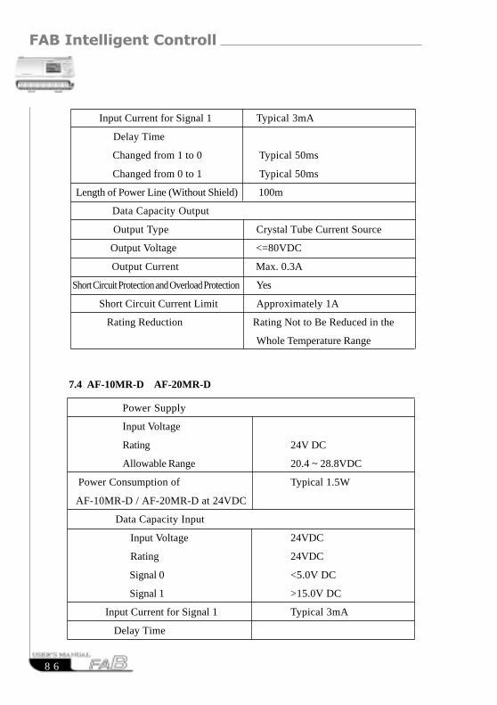
FAB Intelligent Controller
8 6
Input Current for Signal 1 Typical 3mA
Delay Time
Changed from 1 to 0 Typical 50ms
Changed from 0 to 1 Typical 50ms
Length of Power Line (Without Shield) 100m
Data Capacity Output
Output Type Crystal Tube Current Source
Output Voltage <=80VDC
Output Current Max. 0.3A
Short Circuit Protection and Overload Protection Yes
Short Circuit Current Limit Approximately 1A
Rating Reduction Rating Not to Be Reduced in the
Whole Temperature Range
7.4 AF-10MR-D AF-20MR-D
Power Supply
Input Voltage
Rating 24V DC
Allowable Range 20.4 ~ 28.8VDC
Power Consumption of Typical 1.5W
AF-10MR-D / AF-20MR-D at 24VDC
Data Capacity Input
Input Voltage 24VDC
Rating 24VDC
Signal 0 <5.0V DC
Signal 1 >15.0V DC
Input Current for Signal 1 Typical 3mA
Delay Time

Chapter VII Technical specifications
8 7
Changing from 1 to 0 Typical 50ms
Changing from 0 to 1 Typical 50ms
Length of power line (Without Shield) 100m
Data Capacity Output Dyital Value Output
Output Type Relay Output
Electrical Isolation Yes
Group 1
Continuous Current Ith Max. 10A
Incandescent Lamp Load 1000W
(25,000 switch cycles)
Fluorescent Light Tube with Electrical Controller 10 x 58W
(25,000 switch cycles)
Fluorescent Light Tube with Regular 1 x 58W
Compensation(25,000 switch cycles)
Fluorescent Light Tube without 10 x 58W
Compensation(25,000 switch cycles)
Short Circuit Protection cos 1 Power Supply Protection B16, 600A
Short Circuit Protection cos 0.5 ~ 0.7 Power Supply Protection B16, 900A
Parallel connected Output Increased Power Not Allowed
Output Relay Protection Max. 20A Feature B16
Switch Frequency
Mechanical 10Hz
Resistor Load/Lamp Load 2Hz
Induced Load 0.5Hz

FAB Intelligent Controller
8 8
RESUMERESUME
7.5 Telephone Number Receive and Transmit and Voice Block (Optional)
Index Conformity
Automatic Receive CCITT-DTMF
Automatic transmit CCITT-DTMF
Voice Record and Play Max. 98 segments,
Each with Arbitrary Length (16min)

Chapter VIII Application
8 9
Chapter VIII Application
FAB has a very wide application range. In order to let the users understand the
wide application space of FAB and the convenience brought by using of FAB, we
will show some common and representative control schemes herein. After you have
read these application examples, you will realize how simple and easy it is to use
FAB to satisfy your automatic control requirements, especially in a system requir-
ing time control and in automatic control of intelligent living quarters.
8.1 Bell control of schools or factories
Control requirements:
Monday to Friday: 6:00:00 to 12:00:00 AM, the bell shall ring once every hour
for 10 seconds; 14:00:00 to 17:00:00 PM, the bell shall ring once every hour for
10 seconds;
Saturday and Sunday: 8:00:00 to 12:00:00 AM, the bell shall ring once every 2
hours for 10 seconds; 13:00:00 to 17:00:00 PM, the bell shall ring once every 2
hours for 10 seconds.
Analysis:
To realize the above control, the control of 11 time intervals from Mon to Fri and
6 time intervals on Sat and Sun is necessary. In the relay control used in the past,
a lot of time-delayed relays are needed and the line connection is quite complicated.
Using FAB, all these will become very simple. Please refer to the function dia-
gram for realization of the control, as shown in the following figure. There is only
one line section for its required external connection, which means that you can
realize the timing control of the school bell only by connecting one output of FAB
directly to the bell. The program diagram is as follows:
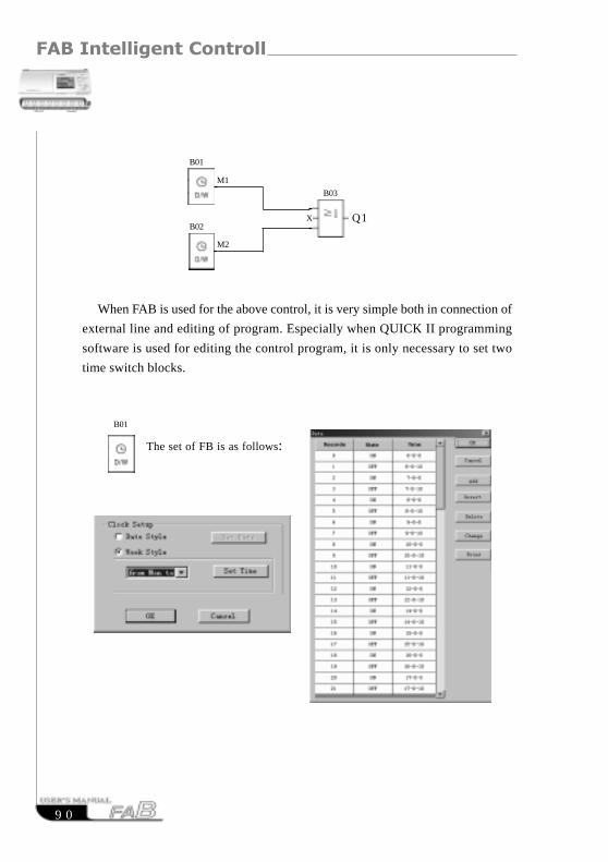
FAB Intelligent Controller
9 0
When FAB is used for the above control, it is very simple both in connection of
external line and editing of program. Especially when QUICK II programming
software is used for editing the control program, it is only necessary to set two
time switch blocks.
X Q1
B01
B02
M1
M2
B03
The set of FB is as follows:
B01

Chapter VIII Application
9 1
8.2 The illumination of Multi-function switch in stairs,halls or passagewaysRequirements:
1.When switch being pressed,the illumination will be connected and be cut offautomatically after the set time 3m
2.Lights glimmer the 5s before being sut off.
3. When switch being pressed twice, the illumination will be on as usual.
4.When switch being pressed for more than 2s,the illumination will be on as usual.
5.The illumination will automatically and be cut off every day at PM6:30 and becut off every day at AM6:30,The Functiooon Block Program Diagram 3s as follows:
X
XQ1
B04
B03 B07
B02
B09 B10
M1
M3
M7M8
I1
t=2.91min
t=2s counter=2
from monday to sunday
6:30-18:30
M2
t
I1
B01
t=2.92min
t
t
M5
t=5s
B05M4
t
B06
M6
t=0.5s
t
I1B08
M9
The set of FB is as follows:B02
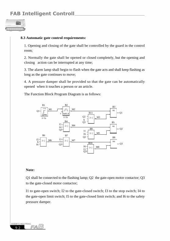
FAB Intelligent Controller
9 2
Note:
Q1 shall be connected to the flashing lamp; Q2 the gate-open motor contactor; Q3
to the gate-closed motor contactor;
I1 to gate-open switch; I2 to the gate-closed switch; I3 to the stop switch; I4 to
the gate-open limit switch; I5 to the gate-closed limit switch; and I6 to the safety
pressure damper.
8.3 Automatic gate control requirements:
1. Opening and closing of the gate shall be controlled by the guard in the controlroom;
2. Normally the gate shall be opened or closed completely, but the opening andclosing action can be interrupted at any time;
3. The alarm lamp shall begin to flash when the gate acts and shall keep flashing aslong as the gate continues to move;
4. A pressure damper shall be provided so that the gate can be automaticallyopened when it touches a person or an article.
The Function Block Program Diagram is as follows:
Q2
Q3
Q2
Q3
Q1
Q2
Q3X
X
I1
I5
I6
I3I4
I3
I1I6
I6
M6
M4
M7
M3
M5
M8
B6
B4
B7
B11
B9
B10
B8
B3
B5
Q1M1 M2
B1
t=1s t=1s
B2
t MPLR
Q2
Q3

Chapter VIII Application
9 3
8.4 Ventilation system
Requirements: The ventilation system shall be able both to send fresh air into the
room and to exhaust the waste gas out of the room;
1. Waste gas exhaust unit and fresh air forced-draft unit shall be installed in the
room;
2. The ventilation system shall be controlled by the control monitor;
3. No over atmospheric pressure is allowed in the room any time;
4. The fresh air forced-draft unit can not be put into service until the flow monitor
indicates that the waste gas exhaust unit is in normal operation;
5. In case of any fault in the ventilation system, the alarm lamp shall be on.
The Function Block Program Diagram is as follows:
Note:
Q1 shall be connected to the contactor of waste gas exhaust unit;
Q2 to the contactor of the fresh air forced-draft unit;
Q3 to the fault alarm lamp;
I1 to the activate exhaust switch;
I2 to the stop exhaust switch;
I3 to the waste gas flow monitor;
I4 to the fresh air flow monitor.
X
X
X
X
XI2
I1
I3
I2
I3
I4
Q1
Q2
Q1Q2
Q3
Q1Q3
B4
B5
B6
B7
B1
B8
B3
B10B9
B2
M2
M4
M3
M5
M6 M7
M1
t=0.5s
t

FAB Intelligent Controller
9 4
8.5 Control requirements for neon lamp control system:
1. Display mode, for example: Array Electronics Welcomes You !
1.1 Displaying “Array”
1.2 Displaying “Array Electronics”
1.3 Displaying “Welcomes You!”
1.4 Displaying “Array Electronics Welcomes You”
1.5 Displaying “Welcomes You!”
1.6 Displaying “Array Electronics”
1.7 Cycling 1.1 ~ 1.6
2. Control requirements
1) The neon lamp shall be automatically turned on at 18:00 and off at 24:00 every day;
2) The control can be switched over with the manual/automatic/off selection switch:
Manual: The neon lamp control system can be activated through the manual switch
-at any time;
Automatic: The neon lamp control system can be automatically activated when
the clock switch or light sensitive switch triggers the output;
Off: The neon lamp system shall be switched off as the manual/automatic/off selec-
tion switch is pressed twice and switched on as it is pressed for the third time;
3) The light sensitive switch shall be provided to complement the time switch so that
the lamp will be automatically turned on when the light is weak and off when
thelight is sufficient;
4) Rain detector: On a rainy day, the neon lamp system shall be automatically switched
off;
5) Over (under) voltage detector: The system will be automatically switched off when
the operating voltage of the neon lamp is too high or too low.
3. Input/output assignment
I1 rain detector;
I2 over (under) voltage detector;

Chapter VIII Application
9 5
I3 light sensitive switch;
I4 manual/ automatic/off selection switch;
Q1 to be connected to the enable terminal of “Array” segment;
Q2 to the enable terminal of “Electronics” segment;
Q3 to the enable terminal of “Welcome You!” segment.
Following is the Function Block Program Diagram:
B1
M9M12
M4
Monday to Sunday
18:00-24:00
B16I1
I2
Monday to Sunday
0:00-10:00
B13B7
M8 M1
B19
M5M17
t=1s
t
B8
M15
M6M13
Counter=2B17
M13M15
t=1s
t
B9
M10
I4
M6
Counter=1
B4
M12 M11
M10
B32M21
M33M26
B23M30
t=20s
tQ1
B33
M27M28
M10 M3
M9
B2
M20I1I2
B24B28
M33
M21 M22
M29
t=10st=10s
tt
Q3
B25B29M21 M23
M33
t=30st=20s
tt
M23M21
B26B30
M33
t
M27
t=10st=30s
t
B36B37
M31 M32
M33
t=1s
B31B27
M25M21
M28
t=10st=50s
t M33t
B15
M10M6
t=1s
t
B5
M2
M10
B3
M5M4
M2
B12
M4
B6M12
I3
M20
B22
M19
B20
M9
t=1s
t
M16 M18
B18M17
B11
M31
M19
B21
B14
M15M13
M14
B10
M18
B34
Q2M27M28
M29
M30
B35
M25
t=10s
t
t

FAB Intelligent Controller
9 6
8.6 Display the illumination system of the windows
Control requirements:
1. Basic lighting for display period:
a) Time:
Monday to Friday 8:00~22:00;
On Saturday 8:00~24:00;
On Sunday 9:00~20:00;
b) Automatic on/off: the light can automatically turn off the minimum illumi-
nance maintaining and the focus lamps when it is off
2. Additional regnirements for night lighting :
a) Time:
Monday to Friday light sensitive switch is triggered at 22:00 ;
On Saturday light sensitive switch is triggered at 24:00;
On Sunday light sensitive switch is triggered at 20:00 ;
b) Light sensitive switch triggering/ automatic off: the light can automatically
turn off the minimum illuminance maintaining and the focus lamps when it is
on and can automatically turn on to the minimum illuminance maintaining and
the focus lamp.
3.Minimum illuminance maintaining and focus lamp in non-display period:
a) The minimum illuminance maintaining and the focus lamps shall be main-
tained and the focus lamp shall be automatically turned on when the show time
ends and the basic lighting and additional night lighting are turned off.
4. Test switch:
All lamp groups can be tested when the test switch is pressed.

Chapter VIII Application
9 7
Note:
I1 shall be connected to the light sensitive switch;
I2 to the auto/manual selection switch;
I3 to the test switch;
Q1 to the basic lighting in display period;
Q2 to the night additional lighting within display period;
Q3 to the minimum illumination maintaining during non-display period;
Q4 to the projection light for special commodities in non-display period.
8.7 Application of FAB in building management
Control requirements:
1. Automatic reading of various meters: the watt-hour meter, water meter and gas
meter can be read automatically;
On Sunday
8:00-20:00
Monday to Friday
8:00-22:00
On Saturday
8:00-24:00
Q1
Q2
Q3
Q4X
XX
X
I2
I2
I1
I1 I3
I3
I3
I 2
B1
B2
B3
M1
M2
M3
B4
B5
B6
B7
B8B9
B10
B11
B12
M4
M6
M7
M9M8
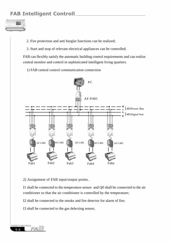
FAB Intelligent Controller
9 8
2. Fire protection and anti burglar functions can be realized;
3. Start and stop of relevant electrical appliances can be controlled.
FAB can flexibly satisfy the automatic building control requirements and can realize
central monitor and control in sephisticated intelligent living quarters.
1) FAB central control communication connection
2) Assignment of FAB input/output points.
I1 shall be connected to the temperature sensor and Q0 shall be connected to the air
conditioner so that the air conditioner is controlled by the temperature;
I2 shall be connected to the smoke and fire detector for alarm of fire;
I3 shall be connected to the gas delecting sensor,
}485Signal bus
}485Power Bus
AF-P485
A
B
PC
Fab1 Fab2 Fab3 Fab4 Fabn
AF-C485 AF-C485AF-C485 AF-C485AF-C485

Chapter VIII Application
9 9
Q1 shall be connected to the ventilation equipment and Q2 shall be connected to
the alarm so that the ventilation equipment is controlled by the air status;
I4 shall be connected to the door/window sensor activating the alarm
I5 shall be connected to the water meter, while I6 shall be connected to the
watthour meter.
8.8 Application of FAB in a voltage-resistance of the diode counting and
packing assembly line
The PC Assembly Line Central Control System Diagram is as follows:
AF-P485
}}
A
B
Fab1 Fab2 Fab3 Fab4 Fabn
AF-C485 AF-C485AF-C485 AF-C485AF-C485
2000v-
Resisting
Assembly Line
PC
485Power Bus
485Signal bus
1500v-
Resisting
Assembly Line
1000v-
Resisting
Assembly Line
500v-
Resisting
Assembly Line
80v-
Resisting
Assembly Line

FAB Intelligent Controller
100
Control requirements and configuration:
1. Control of 2000V withstand voltage counting flow line, to be completed by
FAB1
1) I5 is used for counting the diodes entering the flow line (automatically giving
the sum of the diodes to be tested);
2) I6 is used for counting of diodes with 2000V withstand voltage;
3) Q1 is used for labeling of diodes with acceptable withstand voltage;
4) Q2 is used for enclosing of diodes already labeled;
5) If the counting value of I6 is multiples of 1000, Q3 will be switched on to
start the packing equipment;
6) Diodes that can not withstand 2000V voltage shall be transferred to 1500V flow
line.
2. Control shall be completed by FAB2 for 1500V withstand voltage assembly
line, by FAB3 for 1000V withstand voltage flow line, by FAB4 for 500V
withstand voltage flow line and by FAB5 for 80V withstand voltage flow line.
The control require ments and configuration are the same as mentioned above.
3. Monitoring of all FAB’s can be realized by installation of monitoring soft-
ware
FAB-SCADA on PC. Each FAB answers through bus 485 the instructions
fromPC, including diode counting and input/output (I/O) status of FAB; PC will
displayeach acquired FAB data on the screen and can provide data storage and
inquiry functions, to allow prompt analysis of the counting of different with-
stand volt age diodes.

101
Chapter VIIII Quality Guarantee
Quality
Guarantee
Warranty
Period
Warranty
Range
Remark
Note
The product has been strictly tested for quality before
delivery from our plant and it can completely meet various
requirements listed in this manual. Under proper installation it
should work normally as expected.
This product is warranted against defects in material and
manufacturing for a period of one year from the date of
shipment. During the warranty period, ARRAY is responsible
for necessary repairs as long as the product can be proved to be
defective.
During the above mentioned warranty period, if any
damage caused by the product quality, it should be delivered to
some sevice places which ARRAY authorized for free
repairment, buyer should pay the shipping charge to ARRAY.
And ARRAY will repair it and deliver it to buyer freely.
The above warranty will not include the following situation.
1.Improper installation or operation
2.Damages caused by unauthorized dismantle
3.The damages of consumable parts such as rubber cover,
buttons, batteries, relays etc.
Damages caused by uncontrolled reason or natural force.
The above warranty range has no other hidden items
There is only compensation of warranty to buyer. ARRAY
will not be obligated to any duty of direct, indirect, occurrence,
and accident etc.
Anyone one without special training will be forbidden to
dismount the products.
Chapter VIIII Quality Guarantee

FAB Intelligent Controller
102
RESUMERESUME
Related Documents