Welcome message from author
This document is posted to help you gain knowledge. Please leave a comment to let me know what you think about it! Share it to your friends and learn new things together.
Transcript


5-1
Introduction In the upcoming years, exciting new technologies will be developed and implemented to help ease air traffic congestion, add to system capacity, and enhance safety. Some of these seamless changes will be invisible to pilots. Others will entail learning new procedures, aircraft equipment, and systems that will introduce powerful new capabilities and dramatically increase the safety of all flight operations.
Improvement Plans Chapter 5
DHSDOD
FAA DOC
NASA OSTP State/Local NGATS
DOT Government Institute
Industry & Community
Air Navigation Operations and Support
ICAO Flight Operations and Support
Global Harmonization
Super Density Operations
Airport Operations and Support
Flight Planning Flight Data Aeronautical Information
Enterprise Services
EnvironmentLayered
Adaptive Security Surveillance
Net Centric Infrastructure Services
Policy & Regulations
Equivalent Visual Operations
Geospatial Performance Communication
Information Metrics
Position, Navigation, Safety Weather
and Timing
Network-Enabled Information Acess
Next Generation Air Transportation (NextGen) System Next Generation Air Transportation System (NextGen) is a comprehensive overhaul of the National Airspace System (NAS) designed to make air travel more convenient and dependable, while ensuring flights are as safe and secure as possible. It moves away from ground-based surveillance and navigation to new and more dynamic satellite-based systems and procedures, and introduces new technological innovations in areas such as weather forecast, digital communications, and networking. [Figure 5-1] When fully implemented, NextGen will safely allow aircraft to fly more closely together on more direct routes, reducing delays, and providing unprecedented benefits for the environment and the economy through reductions in carbon emissions, fuel consumption, and noise. [Figure 5-2]
Implementation in stages across the United States is due between 2012 and 2025. In order to implement NextGen, the Federal Aviation Administration (FAA) will undertake
a wide-range transformation of the entire United States air transportation system. NextGen consists of the following five systems:
1. Automatic dependent surveillance-broadcast (ADS-B)—will use the global positioning system (GPS) satellite signals to provide air traffic control (ATC) and pilots with more accurate information that keeps aircraft safely separated in the sky and on runways. [Figure 5-3] Aircraft transponders receive GPS signals and use them to determine the aircraft’s precise position in the sky. This and other data is then broadcast to other aircraft and ATC. Once fully established, both pilots and ATC will, for the first time, see the same real-time display of air traffic, substantially improving safety. The FAA will mandate the avionics necessary for implementing ADS-B.
2. System wide information management (SWIM)— will provide a single infrastructure and information management system to deliver high quality, timely data to many users and applications. By reducing
Figure 5-1. Next Generation Air Transportation System (NEXGEN) introduces new technological innovations for weather forecasting, digital communications, and networking.
5-2

Figure 5-2. Satellite-based navigation and tracking allows more aircraft to fly closely together on more direct routes.
Figure 5-3. Automatic Dependent Surveillance-Broadcast (ADS-B) systems.
the number and types of interfaces and systems, SWIM will reduce data redundancy and better facilitate multi- user information sharing. SWIM will also enable new modes of decision-making as information is more easily accessed. [Figure 5-4]
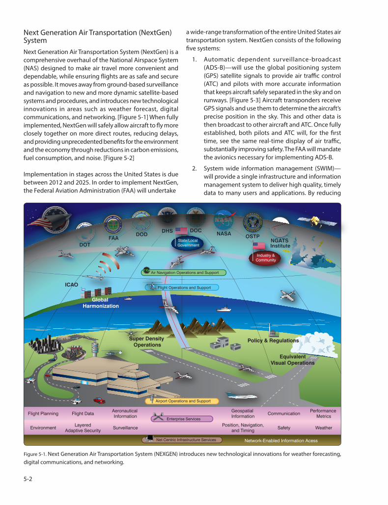
3. Next generation data communications—current communications between aircrew and ATC, and between air traffic controllers, are largely realized through voice communications. Initially, the introduction of data communications will provide an additional means of two-way communication
for ATC clearances, instructions, advisories, flight crew requests, and reports. With the majority of aircraft data link equipped, the exchange of routine controller-pilot messages and clearances via data link will enable controllers to handle more traffic. This will improve ATC productivity, enhancing capacity and safety. [Figure 5-5]
4. Next generation network enabled weather (NNEW)— seventy percent of NAS delays are attributed to weather every year. The goal of NNEW is to cut weather-related delays at least in half. Tens of thousands of global weather observations and sensor reports from ground, airborne, and space-based sources will fuse into a single national weather information system updated in real time. NNEW will provide a common weather picture across the NAS and enable better air transportation decision-making. [Figure 5-6]
5. NAS voice switch (NVS)—there are currently seventeen different voice switching systems in the NAS; some in use for more than twenty years. NVS will replace these systems with a single air/ground and ground/ground voice communications system. [Figure 5-7]
NextGen Existing Improvements The goal of NextGen is to provide new capabilities that make air transportation safer and more reliable while improving the capacity of the NAS and reducing aviation’s
5-3
Today Enterprise Management
Existing systems communication Secure access points for NAS systems structure and data sharing
En Route Data
WeatherSurveillance
SWIMSWIM CoreCoreTerminal
Radar Data ServicesServicesData
Traffic Flow Inter-AgencyManagement
Aeronautical Information
Figure 5-4. System wide information management (SWIM)—an information management system that helps deliver high quality, timely data to improve the efficiency of the national airspace.
Trajectory Based Operations
ARTCCHigh Performance Airspeed
TRACONSTOWERS
S
Clearances WX Reroutes
Time Based Metering
Fix
Optimized Descents (TAPs/CDAs)
ARTCCs
VDL-2 Network VDL-2 User Flight
Operations Tower Control
ARTCSCC
TRACONs Taxi Instructions
Digital ATIS Departure Clearance
Figure 5-5. Next generation data communications provides an additional means of two-way communication for ATC clearances, instructions, advisories, flight crew requests, and reports.
5-4
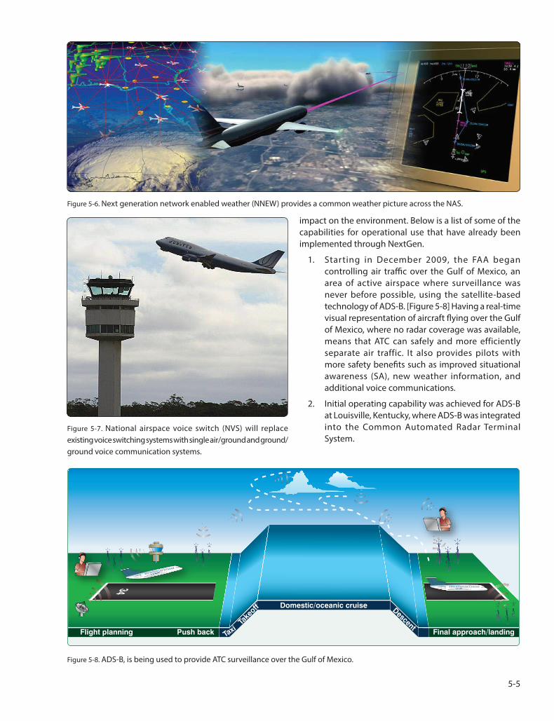
Figure 5-6. Next generation network enabled weather (NNEW) provides a common weather picture across the NAS.
Figure 5-7. National airspace voice switch (NVS) will replace existing voice switching systems with single air/ground and ground/ ground voice communication systems.
impact on the environment. Below is a list of some of the capabilities for operational use that have already been implemented through NextGen.
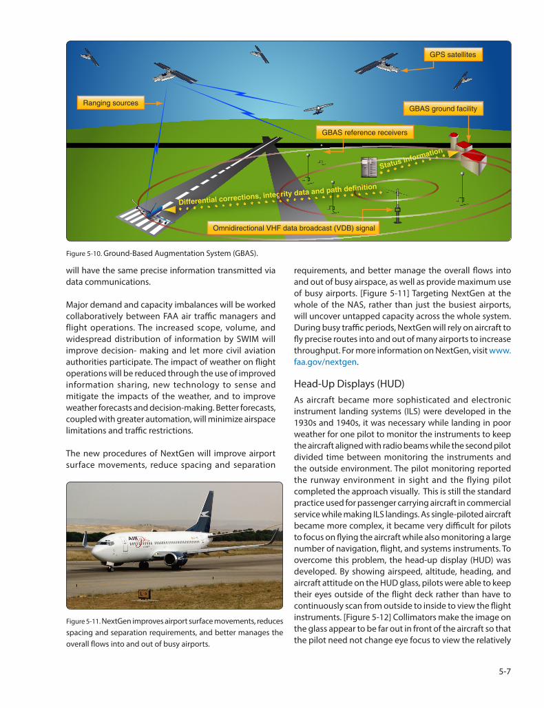
1. Starting in December 2009, the FAA began controlling air traffic over the Gulf of Mexico, an area of active airspace where surveillance was never before possible, using the satellite-based technology of ADS-B. [Figure 5-8] Having a real-time visual representation of aircraft flying over the Gulf of Mexico, where no radar coverage was available, means that ATC can safely and more efficiently separate air traffic. It also provides pilots with more safety benefits such as improved situational awareness (SA), new weather information, and additional voice communications.
2. Initial operating capability was achieved for ADS-B at Louisville, Kentucky, where ADS-B was integrated into the Common Automated Radar Terminal System.
34
Final approach/landingFlight planning Push back
Domestic/oceanic cruise
TaxiTa
keoff Descent
Figure 5-8. ADS-B, is being used to provide ATC surveillance over the Gulf of Mexico.
5-5

GPS satellites
Barrow
Kotzebue
Bethel Fairbanks Iqaluit
Anchorage Juneau
Cold Bay Goose Bay
Winnipeg Gander
Auburn Billings
Olathe Farmington Nashua
Ronkonkoma Freemont Salt Lake Aurora
Oberlin
Longmont Leesburg
Palmdale Memphis
Fort Worth Hampton Albuquerque Houston Jacksonville
Miami San Jose Del Cabo San Juan
Honolulu GEO satellite
Puert Vallarta Mexico City
Merida
Tapachula
Legend GEO satellite
Wide-area reference station (WRS) New WRSs
Wide-area master station (WMS) Ground uplink station
Figure 5-9. Wide Area Augmentation System (WAAS).
5. Multilateration, a ground-based surveillance 3. Satellite-based technologies, including the Wide technology, is being implemented to help improve Area Augmentation System (WAAS), are improving runway access. The FAA installed and is now using access to runways at both large and small airports. wide area multilateration (WAM) systems to control [Figure 5-9] Directions and maps have been published air traffic in Juneau, Alaska, and at four airports in for more than 500 precision-like approaches Colorado. This allows air traffic to be safely separated enabled by WAAS. Localizer performance with by five miles whereas before each aircraft had to clear vertical guidance (LPV) procedures improves the airspace around the airport before the next could access to airports in lower visibility conditions and enter. where obstacles are present. These procedures
are particularly valuable for smaller airports used 6. New runways at Chicago O’Hare, Washington by general aviation. There are now oer 2,300 Dulles, and Seattle-Tacoma Airports opened in LPV procedures available at runways where no November of 2008, which are now beginning to instrument landing system (ILS) is present. have a reduction in delays.
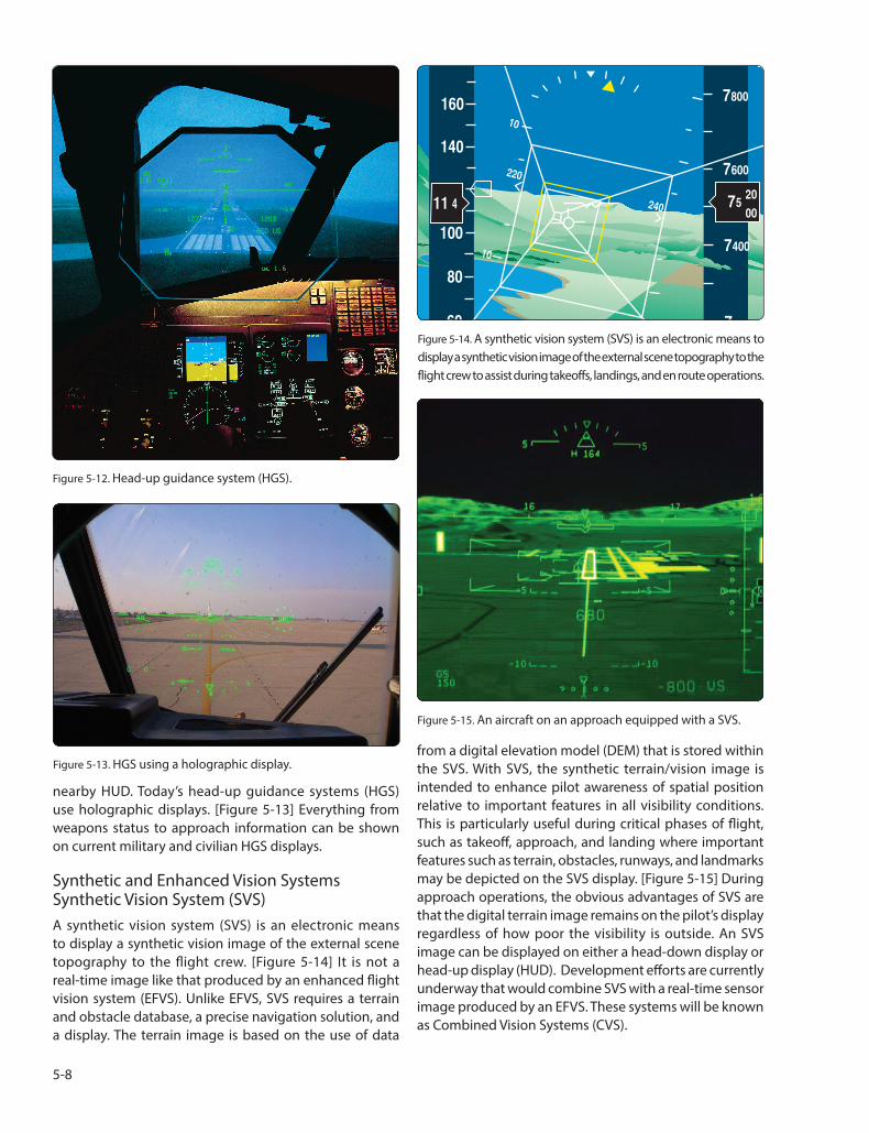
4. The Ground-Based Augmentation System (GBAS) has Benefits of NextGen been approved for Category I operations and the
first satellite-based system has been approved for The implementation of NextGen will allow pilots and this category of precision approach which enables dispatchers to select their own direct flightpaths, rather instrument-based operations down to 200 feet than follow the existing Victor, Jet, and LF/MF airways. Each above the surface even during reduced visibility. airplane will transmit and receive precise information about [Figure 5-10] GBAS was installed at Houston, Texas the time at which it and others will cross key points along and Newark, New Jersey airport in 2009. their paths. Pilots and air traffic managers on the ground
5-6
GPS satellites
Ranging sources
Differential corrections, integrity data and path definition
Omnidirectional VHF data broadcast (VDB) signal
GBAS reference receivers
GBAS ground facility
Status information
Figure 5-10. Ground-Based Augmentation System (GBAS).
will have the same precise information transmitted via data communications.
Major demand and capacity imbalances will be worked collaboratively between FAA air traffic managers and flight operations. The increased scope, volume, and widespread distribution of information by SWIM will improve decision- making and let more civil aviation authorities participate. The impact of weather on flight operations will be reduced through the use of improved information sharing, new technology to sense and mitigate the impacts of the weather, and to improve weather forecasts and decision-making. Better forecasts, coupled with greater automation, will minimize airspace limitations and traffic restrictions.
The new procedures of NextGen will improve airport surface movements, reduce spacing and separation
Figure 5-11. NextGen improves airport surface movements, reduces spacing and separation requirements, and better manages the overall flows into and out of busy airports.
requirements, and better manage the overall flows into and out of busy airspace, as well as provide maximum use of busy airports. [Figure 5-11] Targeting NextGen at the whole of the NAS, rather than just the busiest airports, will uncover untapped capacity across the whole system. During busy traffic periods, NextGen will rely on aircraft to fly precise routes into and out of many airports to increase throughput. For more information on NextGen, visit www. faa.gov/nextgen.
Head-Up Displays (HUD) As aircraft became more sophisticated and electronic instrument landing systems (ILS) were developed in the 1930s and 1940s, it was necessary while landing in poor weather for one pilot to monitor the instruments to keep the aircraft aligned with radio beams while the second pilot divided time between monitoring the instruments and the outside environment. The pilot monitoring reported the runway environment in sight and the flying pilot completed the approach visually. This is still the standard practice used for passenger carrying aircraft in commercial service while making ILS landings. As single-piloted aircraft became more complex, it became very difficult for pilots to focus on flying the aircraft while also monitoring a large number of navigation, flight, and systems instruments. To overcome this problem, the head-up display (HUD) was developed. By showing airspeed, altitude, heading, and aircraft attitude on the HUD glass, pilots were able to keep their eyes outside of the flight deck rather than have to continuously scan from outside to inside to view the flight instruments. [Figure 5-12] Collimators make the image on the glass appear to be far out in front of the aircraft so that the pilot need not change eye focus to view the relatively
5-7
200
Figure 5-12. Head-up guidance system (HGS).
160
140
100
80
60
10
10
411
7800
7600
7400
7
20
00 75
220
240
Figure 5-14. A synthetic vision system (SVS) is an electronic means to display a synthetic vision image of the external scene topography to the flight crew to assist during takeoffs, landings, and en route operations.
from a digital elevation model (DEM) that is stored within Figure 5-13. HGS using a holographic display. the SVS. With SVS, the synthetic terrain/vision image is
Figure 5-15. An aircraft on an approach equipped with a SVS.
nearby HUD. Today’s head-up guidance systems (HGS) use holographic displays. [Figure 5-13] Everything from weapons status to approach information can be shown on current military and civilian HGS displays.
Synthetic and Enhanced Vision Systems Synthetic Vision System (SVS) A synthetic vision system (SVS) is an electronic means to display a synthetic vision image of the external scene topography to the flight crew. [Figure 5-14] It is not a real-time image like that produced by an enhanced flight vision system (EFVS). Unlike EFVS, SVS requires a terrain and obstacle database, a precise navigation solution, and a display. The terrain image is based on the use of data
intended to enhance pilot awareness of spatial position relative to important features in all visibility conditions. This is particularly useful during critical phases of flight, such as takeoff, approach, and landing where important features such as terrain, obstacles, runways, and landmarks may be depicted on the SVS display. [Figure 5-15] During approach operations, the obvious advantages of SVS are that the digital terrain image remains on the pilot’s display regardless of how poor the visibility is outside. An SVS image can be displayed on either a head-down display or head-up display (HUD). Development efforts are currently underway that would combine SVS with a real-time sensor image produced by an EFVS. These systems will be known as Combined Vision Systems (CVS).
5-8

Enhanced Flight Vision System (EFVS)
For an in-depth discussion regarding Enhanced Flight Vision Systems, see Chapter 4.
Developing Combined Technology
The United States air transportation system is undergoing a transformation to accommodate a projected three-fold increase in air operations by 2025. Technological and systemic changes are being developed to significantly increase the capacity, safety, efficiency, and security for this Next Generation Air Transportation System (NextGen). One of the key capabilities envisioned to achieve these goals is the concept of equivalent visual operations (EVO), whereby visual flight rules (VFR) and operating procedures, such as separation assurance, are maintained independent of the actual weather conditions. One methodology by which the
Figure 5-16. Enhanced and synthetic vision displayed on primary flight displays.
goal of EVO might be attainable is to create a virtual visual flight environment for the flight crew, independent of the actual outside weather and visibility conditions, through application of EV and synthetic vision (SV) technologies. [Figure 5-16]
Electronic Flight Bag (EFB) The electronic flight bag (EFB) is a system for pilots or crewmembers that provide a variety of electronic display, content manipulation, and calculation capabilities. Functions include, but are not limited to, aeronautical charts, documents, checklists, weight & balance, fuel calculations, moving maps, and logbooks.
EFB systems may manage information for use in the cockpit, cabin, and/or in support of ground operations and planning. The use of an EFB is unique to each aircraft operator and, depending on the type of operation, EFB use may require an authorization for use from the FAA issued as either an operations specification (OpSpec), maintenance specification (MSpec), or letter of authorization (LOA).
Figure 5-18. Portable flight bag.
Figure 5-17. Installed flight bag.
EFBs can be portable [Figure 5-18] or installed [Figure 5-19] in the aircraft. Portable EFBs may have a provision for securing in the cockpit for use during all phases of flight. The hardware device, whether it’s an installed avionics display or portable commercial-off-the-shelf (COTS) device, commonly referred to as a portable electronic device (PED), is not considered to be an EFB unless the hardware device hosts and actively displays either Type A or B software application(s). A non-inclusive list of Type A and B software application examples can be found in appendix 1 and 2 of FAA Advisory Circular (AC) 120-76.
The purpose, technology, and functions for EFB use are rapidly evolving. New and advanced software applications and databases beyond traditional flight bag uses continue to be developed. The FAA has published and continues to update EFB policy and guidance to educate and assist aircraft operators interested in using or obtaining an EFB authorization as appropriate. The most current editions of the following FAA guidance and policy can be accessed from the FAA’s website (http://www.faa.gov) or FAA’s
5-9

Flight Standards Information Management System (FSIMS http://fsims.faa.gov).
• AC 120-76, Guidelines for the Certification, Airworthiness, and Operational Use of Electronic Flight Bags;
• AC 91-78, Use of Class 1 or Class 2 Electronic Flight Bag (EFB);
• AC 20-173, Installation of Electronic Flight Bag Components;
• FAA Order 8900.1 Volume 4, Chapter 15, Section 1, Electronic Flight Bag authorization for use; and
• FAA Order 8900.1 Volume 3, Chapter 18, Section 3, Part A Operations Specifications - General
Access to Special Use Airspace Special use airspace consists of airspace of defined dimensions identified by an area on the surface of the earth wherein activities must be confined because of their nature, or wherein limitations are imposed upon aircraft operations that are not a part of those activities, or both. Special use airspace includes: restricted airspace, prohibited airspace,
Figure 5-27. Restricted airspace.
Figure 5-28. Prohibited airspace.
Figure 5-29. Military operations area (MOA).
Figure 5-30. Warning area.
Military Operations Areas (MOA), warning areas, alert areas, temporary flight restriction (TFR), and controlled firing areas (CFAs). [Figures 5-27 through 5-32] Prohibited and restricted areas are regulatory special use airspace and are established in 14 CFR Part 73 through the rulemaking process. Warning areas, MOAs, alert areas, and CFAs are non-regulatory special use airspace. All special use airspace descriptions (except CFAs) are contained in FAA Joint Order 7400.8, Special Use Airspace, and are charted on IFR or visual charts and include the hours of operation, altitudes, and the controlling agency. [Figure 5-33]
5-10

Figure 5-31. Alert area.
The vertical limits of special use airspace are measured by designated altitude floors and ceilings expressed as flight levels or as feet above mean sea level (MSL). Unless otherwise specified, the word “to” (an altitude or flight level) means “to and including” (that altitude or flight level). The horizontal limits of special use airspace are measured by boundaries described by geographic coordinates or other appropriate references that clearly define their perimeter. The period of time during which a designation of special use airspace is in effect is stated in the designation.
Civilians Using Special Use Airspace The FAA and the Department of Defense (DOD) work together to maximize the use of special use airspace by opening such areas to civilian traffic when they are not being used by the military. The military airspace management system (MAMS) keeps an extensive database of information on the historical use of special use airspace, as well as schedules describing when each area is expected to be active. MAMS transmits the data to the special use airspace management system (SAMS), an FAA program that provides current and scheduled status information on special use airspace to civilian users. The two systems work together to ensure that the FAA and system users have current information on a daily basis. This information is available 24 hours a day at the following link: http://sua. faa.gov. The website merges information for both special use airspace and TFR making it a single comprehensive source to review airspace closure information.
Figure 5-32. Temporary flight restriction (TFR).
The website contains two tabbed pages, List and Map, that display the scheduling and Notice to Airmen (NOTAM) data for SUAs, military training routes (MTRs), and TFRs. [Figure 5-34] By default, the List tabbed page displays all airspace types, and the Map tabbed page displays all airspace types apart from MTRs and ATC Assigned Airspaces (ATCAAs). Both the List and Map tabbed pages can be filtered to display specific data for an airspace name, type, or group. Groups include SUA, MTR, or TFR. The Map tabbed page provides a graphical depiction of scheduled airspaces that may be customized using a fly-out menu of map display options. This tabbed page also contains look-up functionality that allows a user to locate one or more airports within the map. [Figures 5-35 through 5-38]
Additional navigation features are included which allows the user to pan in any direction by dragging the cursor within the map. A permalink feature is also available that enables a user to bookmark a customized set of map layers that can easily be added to their Internet browser favorites list. Once a specific set of customized map layers has been bookmarked, a user may open that customized map display using the favorites option within their browser menu. The List tabbed page allows a user to view all SUA and MTR scheduling data and NOTAM text for a TFR. This text may be viewed for each NOTAM ID by expanding the NOTAM text section within the List grid or clicking the NOTAM ID to open a TFR Details page. The TFR Details page displays NOTAM text in a form layout for easy reading and includes a mapped image and sectional navigation map if available for the TFR.
5-11
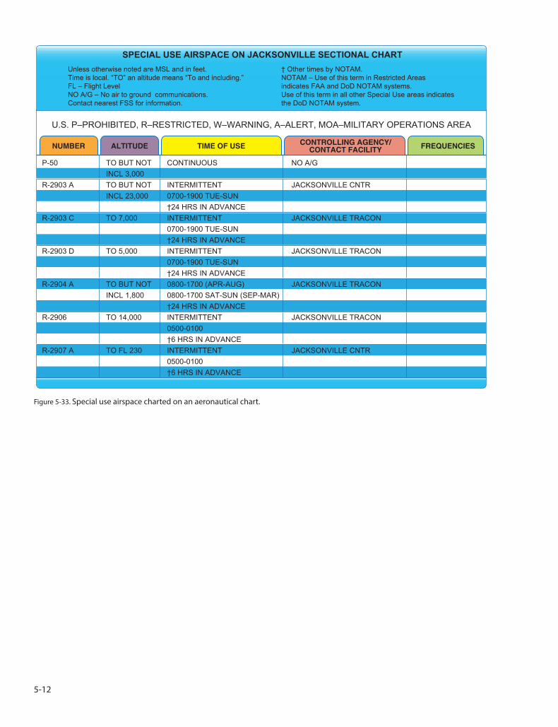
SPECIAL USE AIRSPACE ON JACKSONVILLE SECTIONAL CHART Unless otherwise noted are MSL and in feet. † Other times by NOTAM. Time is local. “TO” an altitude means “To and including.” NOTAM – Use of this term in Restricted Areas FL – Flight Level indicates FAA and DoD NOTAM systems. NO A/G – No air to ground communications. Use of this term in all other Special Use areas indicates Contact nearest FSS for information. the DoD NOTAM system.
U.S. P–PROHIBITED, R–RESTRICTED, W–WARNING, A–ALERT, MOA–MILITARY OPERATIONS AREA
NUMBER ALTITUDE TIME OF USE CONTROLLING AGENCY/CONTACT FACILITY FREQUENCIES
P-50 TO BUT NOT INCL 3,000
R-2903 A TO BUT NOT INCL 23,000
R-2903 C TO 7,000
R-2903 D TO 5,000
R-2904 A TO BUT NOT INCL 1,800
R-2906 TO 14,000
R-2907 A TO FL 230
CONTINUOUS
INTERMITTENT 0700-1900 TUE-SUN †24 HRS IN ADVANCE INTERMITTENT 0700-1900 TUE-SUN †24 HRS IN ADVANCE INTERMITTENT 0700-1900 TUE-SUN †24 HRS IN ADVANCE 0800-1700 (APR-AUG) 0800-1700 SAT-SUN (SEP-MAR) †24 HRS IN ADVANCE INTERMITTENT 0500-0100 †6 HRS IN ADVANCE INTERMITTENT 0500-0100 †6 HRS IN ADVANCE
NO A/G
JACKSONVILLE CNTR
JACKSONVILLE TRACON
JACKSONVILLE TRACON
JACKSONVILLE TRACON
JACKSONVILLE TRACON
JACKSONVILLE CNTR
Figure 5-33. Special use airspace charted on an aeronautical chart.
5-12
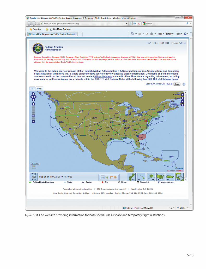
Figure 5-34. FAA website providing information for both special use airspace and temporary flight restrictions.
5-13

Figure 5-35. Center locations and information available to pilots through the FAA website.
5-14
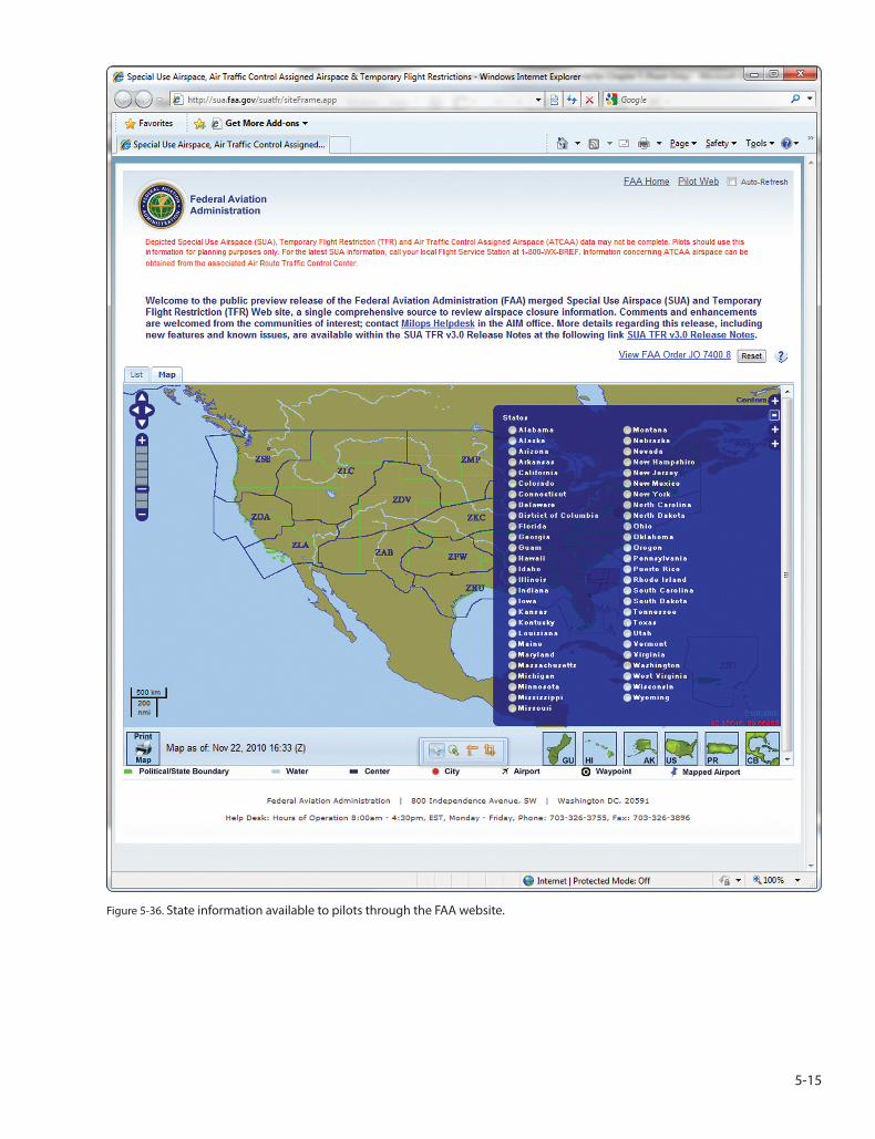
Figure 5-36. State information available to pilots through the FAA website.
5-15

Figure 5-37. Map layer options and information available to pilots through the FAA website.
5-16

Figure 5-38. Airport information available to pilots through the FAA website.
5-17
Related Documents