Liberty Aerospace, Inc. Airplane Flight Manual XL2 FAA APPROVED AIRPLANE FLIGHT MANUAL Liberty Aerospace, Inc. 100 Aerospace Drive, Unit 6 Melbourne, Florida 32901 Serial No. ______________________________________________ Registration No. _________________________________________ Type Certificate No. A00008DE FAA Approved in Normal Category based on FAR 23. This document must be carried in the airplane at all times and be kept within the reach of the pilot during all flight operations. THIS HANDBOOK INCLUDES THE MATERIAL REQUIRED TO BE FUR- NISHED TO THE PILOT BY THE FEDERAL AVIATION REGULATIONS AND ADDITIONAL INFORMATION PROVIDED BY THE MANUFAC- TURER, AND CONSTITUTES THE FAA APPROVED AIRPLANE FLIGHT MANUAL. FAA Approved Ronald F. May, Manager Denver Aircraft Certification Office Federal Aviation Administration Northwest Mountain Region Date P/N 135A-970-005 FAA APPROVED: 2/19/2004 Rev. N Dated: 12/14/2007 i

Welcome message from author
This document is posted to help you gain knowledge. Please leave a comment to let me know what you think about it! Share it to your friends and learn new things together.
Transcript

Liberty Aerospace, Inc. Airplane Flight Manual XL2
FAA APPROVED AIRPLANE FLIGHT MANUAL
Liberty Aerospace, Inc. 100 Aerospace Drive, Unit 6 Melbourne, Florida 32901 Serial No. ______________________________________________ Registration No. _________________________________________ Type Certificate No. A00008DE FAA Approved in Normal Category based on FAR 23. This document must be carried in the airplane at all times and be kept within the reach of the pilot during all flight operations. THIS HANDBOOK INCLUDES THE MATERIAL REQUIRED TO BE FUR-NISHED TO THE PILOT BY THE FEDERAL AVIATION REGULATIONS AND ADDITIONAL INFORMATION PROVIDED BY THE MANUFAC-TURER, AND CONSTITUTES THE FAA APPROVED AIRPLANE FLIGHT MANUAL. FAA Approved Ronald F. May, Manager Denver Aircraft Certification Office Federal Aviation Administration Northwest Mountain Region Date
P/N 135A-970-005 FAA APPROVED: 2/19/2004 Rev. N Dated: 12/14/2007 i

Copyright © 2004 - All Rights Reserved Liberty Aerospace, Incorporated
100 Aerospace Drive, Unit 6 Melbourne, Florida 32901
(800) 759-5953
Airplane Flight Manual Liberty Aerospace, Inc. XL2
FAA APPROVED: 2/19/2004 P/N 135A-970-005 ii Rev. N Dated: 12/14/2007
Liberty Aerospace, Inc. Airplane Flight Manual XL2
P/N 135A-970-005 FAA APPROVED: 2/19/2004 Revision R Dated; 08/18/2009 Page iii
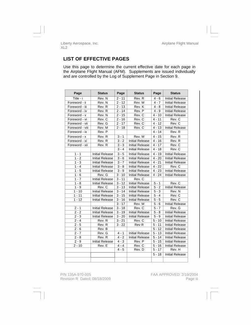
LIST OF EFFECTIVE PAGES Use this page to determine the current effective date for each page in the Airplane Flight Manual (AFM). Supplements are issued individually and are controlled by the Log of Supplement Page in Section 9.
Page Status Page Status Page Status Title - i Rev. N 2 - 11 Rev. R 4 - 6 Initial Release
Foreword - ii Rev. N 2 - 12 Rev. M 4 - 7 Initial Release Foreword - iii Rev. R 2 - 13 Rev. K 4 - 8 Initial Release Foreword - iv Rev. R 2 - 14 Rev. P 4 - 9 Initial Release Foreword - v Rev. N 2 - 15 Rev. C 4 - 10 Initial Release Foreword - vi Rev. C 2 - 16 Rev. C 4 - 11 Rev. C Foreword - vii Rev. G 2 - 17 Rev. C 4 - 12 Rev. C Foreword - viii Rev. M 2 - 18 Rev. C 4 - 13 Initial Release Foreword - ix Rev. P 4 - 14 Rev. R Foreword - x Rev. R 3 - 1 Rev. M 4 - 15 Rev. R Foreword - xi Rev. R 3 - 2 Initial Release 4 - 16 Rev. R Foreword - xii Rev. R 3 - 3 Initial Release 4 - 17 Rev. C
3 - 4 Initial Release 4 - 18 Rev. C 1 - 1 Initial Release 3 - 5 Initial Release 4 - 19 Initial Release 1 - 2 Initial Release 3 - 6 Initial Release 4 - 20 Initial Release 1 - 3 Initial Release 3 - 7 Initial Release 4 - 21 Initial Release 1 - 4 Initial Release 3 - 8 Initial Release 4 - 22 Rev. C 1 - 5 Initial Release 3 - 9 Initial Release 4 - 23 Initial Release 1 - 6 Rev. G 3 - 10 Initial Release 4 - 24 Initial Release 1 - 7 Initial Release 3 - 11 Rev. C 1 - 8 Initial Release 3 - 12 Initial Release 5 - 1 Rev. C 1 - 9 Rev. C 3 - 13 Initial Release 5 - 2 Initial Release
1 - 10 Initial Release 3 - 14 Initial Release 5 - 3 Rev. N 1 - 11 Initial Release 3 - 15 Initial Release 5 - 4 Rev. C 1 - 12 Initial Release 3 - 16 Initial Release 5 - 5 Rev. C
3 - 17 Rev. M 5 - 6 Initial Release 2 - 1 Initial Release 3 - 18 Rev. C 5 - 7 Rev. G 2 - 2 Initial Release 3 - 19 Initial Release 5 - 8 Initial Release 2 - 3 Initial Release 3 - 20 Initial Release 5 - 9 Initial Release 2 - 4 Rev. R 3 - 21 Rev. C 5 - 10 Initial Release 2 - 5 Rev. R 3 - 22 Rev R 5 - 11 Initial Release 2 - 6 Rev. B 5 - 12 Initial Release 2 - 7 Rev. G 4 - 1 Initial Release 5 - 13 Initial Release 2 - 8 Rev. R 4 - 2 Initial Release 5 - 14 Initial Release 2 - 9 Initial Release 4 - 3 Rev. P 5 - 15 Initial Release
2 - 10 Rev. E 4 - 4 Rev. C 5 - 16 Initial Release 4 - 5 Rev. D 5 - 17 Rev. H 5 - 18 Initial Release

Airplane Flight Manual Liberty Aerospace, Inc. XL2
FAA APPROVED: 2/19/2004 P/N 135A-970-005 Page iv Revision R Dated; 08/18/2009
LIST OF EFFECTIVE PAGES (Cont.) Use this page to determine the current effective date for each page in the Airplane Flight Manual (AFM). Supplements are issued individually and are controlled by the Log of Supplement Page in Section 9.
Page Status Page Status Page Status 6 - 1 Initial Release 7 - 24 Rev. C 8 - 1 Initial Release 6 - 2 Initial Release 7 - 25 Rev. C 8 - 2 Initial Release 6 - 3 Initial Release 7 - 26 Rev. C 8 - 3 Initial Release 6 - 4 Initial Release 7 - 27 Rev. C 8 - 4 Initial Release 6 - 5 Rev. G 7 - 28 Rev. C 8 - 5 Initial Release 6 - 6 Rev. G 7 - 29 Rev. C 8 - 6 Initial Release 6 - 7 Rev. G 7 - 30 Rev. C 8 - 7 Initial Release 6 - 8 Rev. M 7 - 31 Rev. C 8 - 8 Initial Release 6 - 9 Rev. G 7 - 32 Rev. C 8 - 9 Initial Release
6 - 10 Rev. G 7 - 33 Rev. C 8 - 10 Initial Release 6 - 11 Rev. M 7 - 34 Rev. C 8 - 11 Initial Release 6 - 12 Rev. M 7 - 35 Rev. C 8 - 12 Initial Release 6 - 13 Rev. M 7 - 36 Rev. C 8 - 13 Initial Release 6 - 14 Rev. M 7 - 37 Rev. C 8 - 14 Initial Release 6 - 15 Rev. M 7 - 38 Rev. C 8 - 15 Initial Release 6 - 16 Rev. G 7 - 39 Rev. D 8 - 16 Initial Release 6 - 17 Rev. G 7 - 40 Rev. C 8 - 17 Initial Release 6 - 18 Initial Release 7 - 41 Rev. R 8 - 18 Initial Release
7 - 42 Rev. C 8 - 19 Initial Release 7 - 1 Rev. C 7 - 43 Rev. C 8 - 20 Initial Release 7 - 2 Rev. C 7 - 44 Rev. C 7 - 3 Rev. C 7 - 45 Rev. C 7 - 4 Rev. C 7 - 46 Rev. C 7 - 5 Rev. C 7 - 47 Rev. C 7 - 6 Rev. C 7 - 48 Rev. C 7 - 7 Rev. R 7 - 49 Rev. C 7 - 8 Rev. C 7 - 50 Rev. R 7 - 9 Rev. C 7 - 51 Rev. C
7 - 10 Rev. C 7 - 52 Rev. C 7 - 11 Rev. C 7 - 53 Rev. C 7 - 12 Rev. C 7 - 54 Rev. C 7 - 13 Rev. R 7 - 55 Rev. C 7 - 14 Rev. C 7 - 56 Rev. C 7 - 15 Rev. C 7 - 57 Rev. C 7 - 16 Rev. C 7 - 58 Rev. C 7 - 17 Rev. C 7 - 59 Rev. C 7 - 18 Rev. C 7 - 60 Rev. C 7 - 19 Rev. C 7 - 61 Rev. C 7 - 20 Rev. C 7 - 62 Rev. C 7 - 21 Rev. C 7 - 22 Rev. C 7 - 23 Rev. C

Liberty Aerospace, Inc. Airplane Flight Manual XL2
FOREWORD This Airplane Flight Manual has been produced by Liberty Aerospace, Inc. to familiarize operators with the XL2 airplane. This manual provides operational procedures written in accordance with the Federal Aviation Regulations and contains additional information provided by the manu-facturer, and constitutes the Federal Aviation Administration Approved Airplane Flight Manual.
REVISING THE MANUAL
Numbered revisions are printed on white paper, normally cover several subjects, and provide general updates to the Manual. Each revision is issued with a new revised page, identifying the revised paragraph(s) with revision bars. An instruction sheet shall accompany the numbered revi-sion page(s) to provide instructions on how to remove the superseded pages and inserting new revised pages.
Revision service for this manual is provided at no cost for the FAA Ap-proved Airplane Flight Manual assigned to an airplane. Additional cop-ies of the manual and revision service can be obtained from Liberty’s Customer Support at the following address:
Customer Support Liberty Aerospace, Inc. 100 Aerospace Drive, Unit 6 Melbourne, Florida 32901 Toll free: (800) 759-5953 Fax: (321) 752-0377
The information presented in this manual is the result of extensive flight tests. If new procedures or performance data are developed, they will be sent in an FAA Approved AFM Revision to the owner on record for each airplane.
NOTE It is the responsibility of the owner to ensure that the Airplane Flight Manual is current at all times. Therefore, it is very important that all revisions be properly incorporated into this Manual as soon as they are received.
P/N 135A-970-005 FAA APPROVED: 2/19/2004 Rev. N Dated: 12/14/2007 v
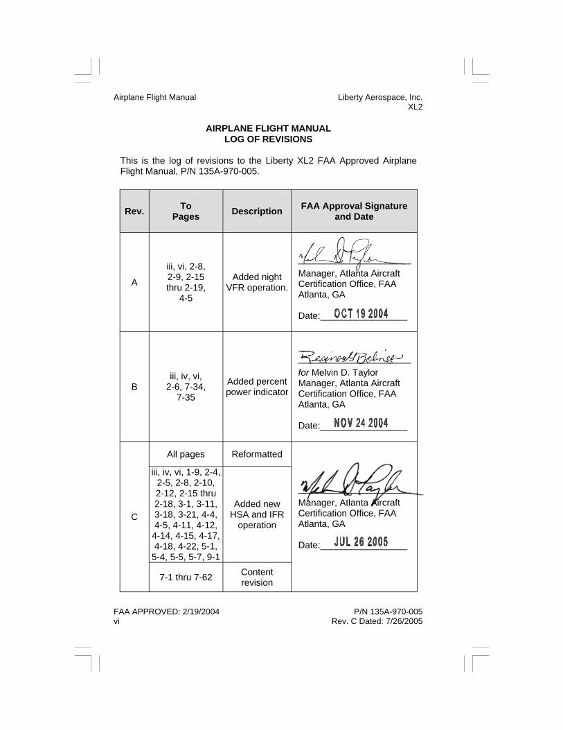
AIRPLANE FLIGHT MANUAL LOG OF REVISIONS
This is the log of revisions to the Liberty XL2 FAA Approved Airplane Flight Manual, P/N 135A-970-005.
Rev. To Pages Description
FAA Approval Signature
and Date
A
iii, vi, 2-8, 2-9, 2-15 thru 2-19,
4-5
Added night VFR operation.
______________________ Manager, Atlanta Aircraft Certification Office, FAA Atlanta, GA Date:_________________
B iii, iv, vi,
2-6, 7-34, 7-35
Added percent power indicator
______________________ for Melvin D. Taylor Manager, Atlanta Aircraft Certification Office, FAA Atlanta, GA Date:_________________
C
All pages Reformatted
______________________ Manager, Atlanta Aircraft Certification Office, FAA Atlanta, GA Date:_________________
iii, iv, vi, 1-9, 2-4, 2-5, 2-8, 2-10, 2-12, 2-15 thru 2-18, 3-1, 3-11, 3-18, 3-21, 4-4, 4-5, 4-11, 4-12,
4-14, 4-15, 4-17, 4-18, 4-22, 5-1,
5-4, 5-5, 5-7, 9-1
Added new HSA and IFR
operation
7-1 thru 7-62 Content revision
Airplane Flight Manual Liberty Aerospace, Inc. XL2
FAA APPROVED: 2/19/2004 P/N 135A-970-005 vi Rev. C Dated: 7/26/2005

Liberty Aerospace, Inc. Airplane Flight Manual XL2
AIRPLANE FLIGHT MANUAL LOG OF REVISIONS
(Cont.)
Rev. To Pages Description
FAA Approval Signature
and Date
D iii, iv, vii, viii,
2-10, 2-11, 2-12, 2-13, 4-5, 7-39
Changed placard
descriptions and fuel
selector valve operation.
______________________ for Melvin D. Taylor Manager, Atlanta Aircraft Certification Office, FAA Atlanta, GA Date:_________________
E iii, iv, vii, 2-10,
2-11, 2-12, 2-13, 4-14, 7-13
Changed HSA indication and
added new door description
and placards.
______________________ for Melvin D. Taylor Manager, Atlanta Aircraft Certification Office, FAA Atlanta, GA Date:_________________
F iii, vii, 2-10 Added fuel vent placard
______________________ for Melvin D. Taylor Manager, Atlanta Aircraft Certification Office, FAA Atlanta, GA Date:_________________
G
iii, vii, 1-6, 2-4, 2-7, 5-7, 6-5, 6-6, 6-7, 6-8,
6-9, 6-10, 6-11, 6-12, 6-13, 6-14, 6-15, 6-16, 6-17
Added new typical empty weight - CG location, and new forward CG at max
gross weight position
______________________ for Melvin D. Taylor Manager, Atlanta Aircraft Certification Office, FAA Atlanta, GA Date:_________________
P/N 135A-970-005 FAA APPROVED: 2/19/2004 Rev. G Dated: 5/19/2006 vii
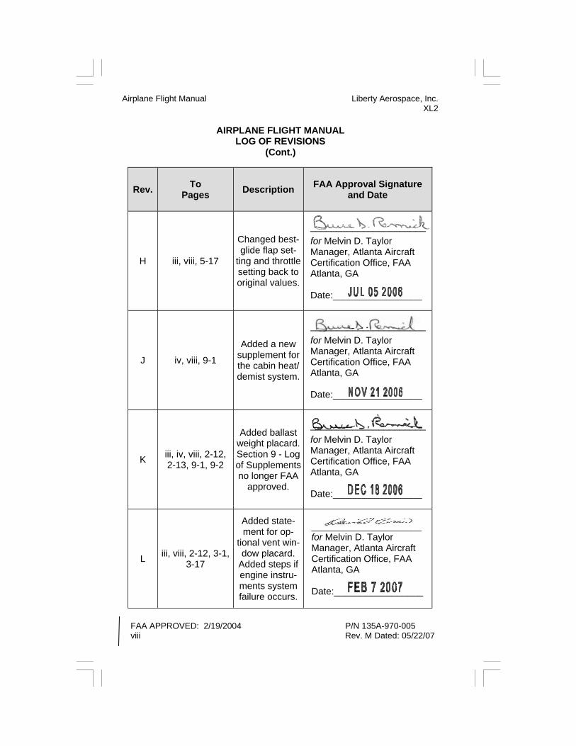
AIRPLANE FLIGHT MANUAL LOG OF REVISIONS
(Cont.)
Airplane Flight Manual Liberty Aerospace, Inc. XL2
FAA APPROVED: 2/19/2004 P/N 135A-970-005 viii Rev. M Dated: 05/22/07
Rev. To Pages Description
FAA Approval Signature
and Date
H iii, viii, 5-17
Changed best-glide flap set-
ting and throttle setting back to original values.
______________________ for Melvin D. Taylor Manager, Atlanta Aircraft Certification Office, FAA Atlanta, GA Date:_________________
J iv, viii, 9-1
Added a new supplement for the cabin heat/demist system.
______________________ for Melvin D. Taylor Manager, Atlanta Aircraft Certification Office, FAA Atlanta, GA Date:_________________
K iii, iv, viii, 2-12, 2-13, 9-1, 9-2
Added ballast weight placard. Section 9 - Log of Supplements no longer FAA
approved.
______________________ for Melvin D. Taylor Manager, Atlanta Aircraft Certification Office, FAA Atlanta, GA Date:_________________
L iii, viii, 2-12, 3-1, 3-17
Added state-ment for op-
tional vent win-dow placard.
Added steps if engine instru-ments system failure occurs.
_____________________ for Melvin D. Taylor Manager, Atlanta Aircraft Certification Office, FAA Atlanta, GA Date:_________________

Liberty Aerospace, Inc. Airplane Flight Manual XL2
AIRPLANE FLIGHT MANUAL
LOG OF REVISIONS (Cont.)
Rev. To Pages Description
FAA Approval Signature and
Date
M
viii, ix, x 2-12, 3-1, 3-17
Reformatted and correction
______________________ for Melvin D. Taylor Manager, Atlanta Aircraft Certification Office, FAA Atlanta, GA Date:_________________
Title, ii, iii, v, 6-8, 6-11, 6-12, 6-13,
6-14, 6-15.
Address changed,
changed pilot, copilot, fuel, and baggage
values to match TCDS
N i, ii, iii, v, ix, 5-3
Changed ad-dress, added statement that
data is applica-ble to aircraft
with and without wheel fairing
installed.
P iii, ix,
2-14, 4-3,
Added Footstep Placard and
Warning.
Melvin D. Taylor Manager, Atlanta Aircraft Certification Office, FAA Atlanta, GA
Date:_________________
______________________ for Melvin D. Taylor Manager, Atlanta Aircraft Certification Office, FAA Atlanta, GA
Date:_________________
P/N 135A-970-005 FAA APPROVED: 2/19/2004 Rev. P Dated: 04/18/2008 ix

Airplane Flight Manual Liberty Aerospace, Inc. XL2
FAA APPROVED: 2/19/2004 P/N 135A-970-005 Page x Revision R Dated; 08/18/2009
AIRPLANE FLIGHT MANUAL LOG OF REVISIONS
(Cont.)
Rev. To Pages Description
FAA Approval Signature
and Date
R
iii, iv, x, xi, xii Added pages to allow for expan-
sion of tables
______________________ for Melvin D. Taylor Manager, Atlanta Aircraft Certification Office, FAA Atlanta, GA Date:_________________
2-4, 2-5 ,2-8, 2-11, 3-22, 4-14, 4-15, 4-16, 7-7,
7-13, 7-41 and 7-50
Sec 2 Corrected Airspeeds,
Negative G, and Oil Temp, added
RPM Placard
Sec3 - Cor-rected note on
flap angles
Sec 4 Added notes on secur-
ing doors
Sec 7—Reworded para-graphs on pages
7,13, and 41 Corrected para-graph on page
50

Liberty Aerospace, Inc. Airplane Flight Manual XL2
P/N 135A-970-005 FAA APPROVED: 2/19/2004 Revision R Dated; 08/18/2009 Page xi
TABLE OF CONTENTS
SECTION 1 GENERAL SECTION 2 LIMITATIONS SECTION 3 EMERGENCY PROCEDURES SECTION 4 NORMAL PROCEDURES SECTION 5 PERFORMANCE SECTION 6 WEIGHT & BALANCE SECTION 7 AIRPLANE & SYSTEMS DESCRIPTION SECTION 8 AIRPLANE HANDLING, SERVICE, & MAINTENANCE SECTION 9 SUPPLEMENTS

Airplane Flight Manual Liberty Aerospace, Inc. XL2
FAA APPROVED: 2/19/2004 P/N 135A-970-005 Page xii Revision R Dated; 08/18/2009
PAGE LEFT INTENTIONALLY BLANK
Liberty Aerospace, Inc. Section 1 XL2 GENERAL
P/N 135A-970-005 FAA APPROVED: 2/19/2004 Initial Release Page 1 - 1
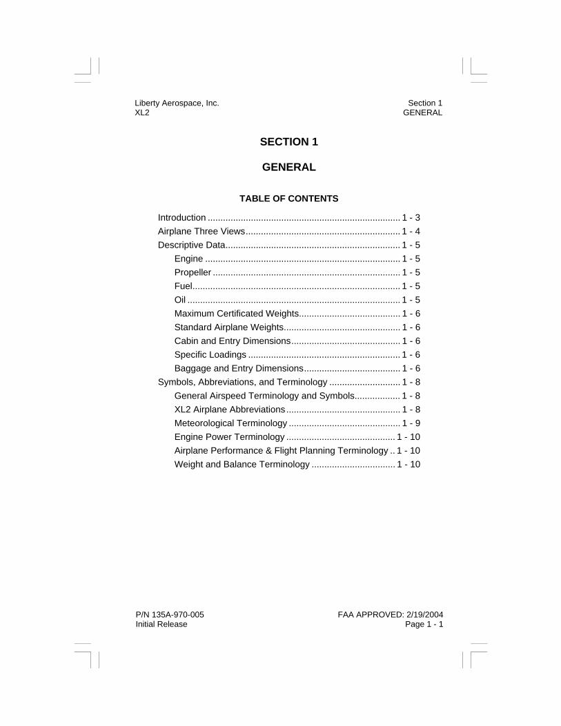
SECTION 1
GENERAL
TABLE OF CONTENTS
Introduction ............................................................................ 1 - 3 Airplane Three Views............................................................. 1 - 4 Descriptive Data..................................................................... 1 - 5 Engine ............................................................................. 1 - 5 Propeller .......................................................................... 1 - 5 Fuel.................................................................................. 1 - 5 Oil .................................................................................... 1 - 5 Maximum Certificated Weights........................................ 1 - 6 Standard Airplane Weights.............................................. 1 - 6 Cabin and Entry Dimensions........................................... 1 - 6 Specific Loadings ............................................................ 1 - 6 Baggage and Entry Dimensions...................................... 1 - 6 Symbols, Abbreviations, and Terminology ............................ 1 - 8 General Airspeed Terminology and Symbols.................. 1 - 8 XL2 Airplane Abbreviations............................................. 1 - 8 Meteorological Terminology ............................................ 1 - 9 Engine Power Terminology ........................................... 1 - 10 Airplane Performance & Flight Planning Terminology .. 1 - 10 Weight and Balance Terminology ................................. 1 - 10

Section 1 Liberty Aerospace, Inc. GENERAL XL2
FAA APPROVED: 2/19/2004 P/N 135A-970-005 Page 1 - 2 Initial Release
THIS PAGE INTENTIONALLY LEFT BLANK

Liberty Aerospace, Inc. Section 1 XL2 GENERAL
P/N 135A-970-005 FAA APPROVED: 2/19/2004 Initial Release Page 1 - 3
INTRODUCTION This manual contains the material required to be furnished to the pilot by the United States Code of Federal Regulations Title 14, Part 23. It also contains supplemental data supplied by Liberty Aerospace, Inc.
Section 1 provides basic data and information of general interest. It also contains definitions or explanations of symbols, abbreviations, and termi-nology commonly used.
The following definitions apply to Warnings, Cautions, and Notes found throughout this manual:
WARNING
An operating procedure, or practice, which if not correctly followed, could result in personal injury or loss of life.
CAUTION An operating procedure, or practice, which if not strictly observed, could result in damage or destruction of equipment.
NOTE An operating procedure, practice, condition, etc., which is deemed essential to highlight.

Section 1 Liberty Aerospace, Inc. GENERAL XL2
FAA APPROVED: 2/19/2004 P/N 135A-970-005 Page 1 - 4 Initial Release
AIRPLANE THREE VIEWS
FIGURE 1 - 1 AIRPLANE THREE VIEWS

Liberty Aerospace, Inc. Section 1 XL2 GENERAL
P/N 135A-970-005 FAA APPROVED: 2/19/2004 Initial Release Page 1 - 5
DESCRIPTIVE DATA
ENGINE Number of Engines...................................................................................1 Number of Cylinders.................................................................................4 Engine Manufacturer ............................................... Teledyne Continental Engine Model.................................................... IOF-240-B with FADEC™ Fuel System...........................................................................Fuel Injected Engine Cooling ..........................................................................Air Cooled Engine Type ....................................... Horizontally Opposed, Direct Drive Horsepower Rating..................................................125 HP @ 2800 RPM PROPELLER Propeller Manufacturer....................................................Sensenich Corp. Propeller Model Number ..................................................... W69EK7-63G Number of Blades.....................................................................................2 Propeller Diameter .............................................................................69 in Propeller Type .............................................Wood/Fiberglass, Fixed Pitch FUEL Fuel Capacity................................................................. 29.5 U.S. Gallons Total Usable .................................................................. 28.0 U.S. Gallons Approved Fuel Grades .........................100LL Grade Aviation Fuel (Blue) 100 Grade Aviation Fuel (Green)
WARNING
Use of unapproved fuels may result in engine damage or engine failure.
NOTE
Park the airplane in a level attitude to ensure maximum fueling ca-pacity.
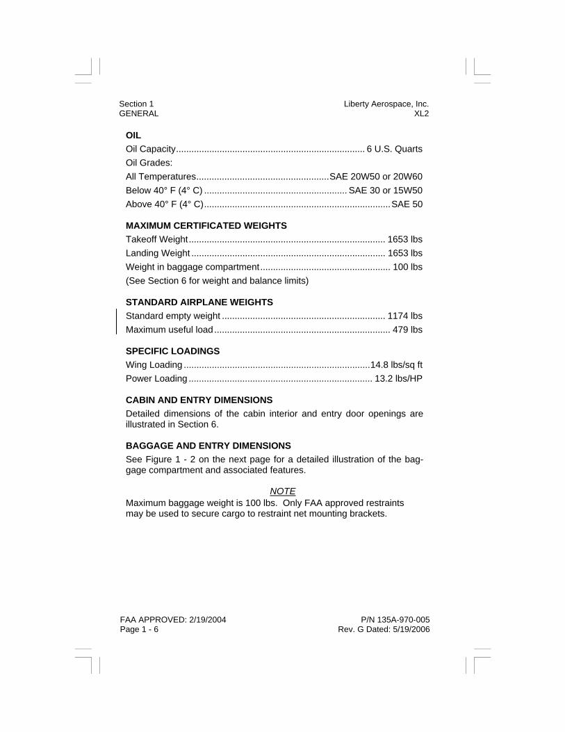
OIL Oil Capacity.......................................................................... 6 U.S. Quarts Oil Grades: All Temperatures....................................................SAE 20W50 or 20W60 Below 40° F (4° C) ........................................................ SAE 30 or 15W50 Above 40° F (4° C).........................................................................SAE 50 MAXIMUM CERTIFICATED WEIGHTS Takeoff Weight............................................................................. 1653 lbs Landing Weight ............................................................................ 1653 lbs Weight in baggage compartment................................................... 100 lbs (See Section 6 for weight and balance limits) STANDARD AIRPLANE WEIGHTS Standard empty weight ................................................................ 1174 lbs Maximum useful load ..................................................................... 479 lbs SPECIFIC LOADINGS Wing Loading .........................................................................14.8 lbs/sq ft Power Loading ........................................................................ 13.2 lbs/HP CABIN AND ENTRY DIMENSIONS Detailed dimensions of the cabin interior and entry door openings are illustrated in Section 6. BAGGAGE AND ENTRY DIMENSIONS See Figure 1 - 2 on the next page for a detailed illustration of the bag-gage compartment and associated features.
NOTE Maximum baggage weight is 100 lbs. Only FAA approved restraints may be used to secure cargo to restraint net mounting brackets.
Section 1 Liberty Aerospace, Inc. GENERAL XL2
FAA APPROVED: 2/19/2004 P/N 135A-970-005 Page 1 - 6 Rev. G Dated: 5/19/2006

Liberty Aerospace, Inc. Section 1 XL2 GENERAL
P/N 135A-970-005 FAA APPROVED: 2/19/2004 Initial Release Page 1 - 7
FIGURE 1 - 2 BAGGAGE BAY DIMENSIONS
Section 1 Liberty Aerospace, Inc. GENERAL XL2
FAA APPROVED: 2/19/2004 P/N 135A-970-005 Page 1 - 8 Initial Release
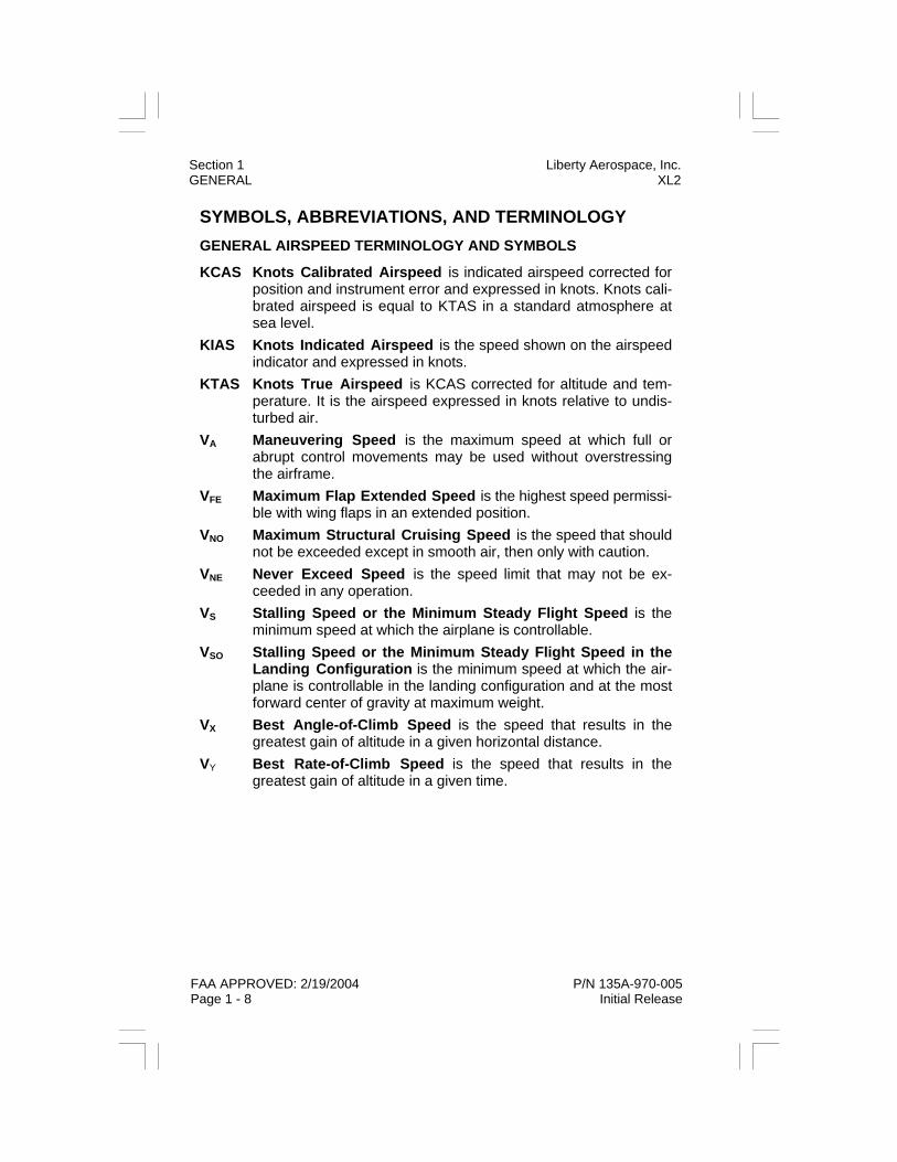
SYMBOLS, ABBREVIATIONS, AND TERMINOLOGY GENERAL AIRSPEED TERMINOLOGY AND SYMBOLS
KCAS Knots Calibrated Airspeed is indicated airspeed corrected for position and instrument error and expressed in knots. Knots cali-brated airspeed is equal to KTAS in a standard atmosphere at sea level.
KIAS Knots Indicated Airspeed is the speed shown on the airspeed indicator and expressed in knots.
KTAS Knots True Airspeed is KCAS corrected for altitude and tem-perature. It is the airspeed expressed in knots relative to undis-turbed air.
VA Maneuvering Speed is the maximum speed at which full or abrupt control movements may be used without overstressing the airframe.
VFE Maximum Flap Extended Speed is the highest speed permissi-ble with wing flaps in an extended position.
VNO Maximum Structural Cruising Speed is the speed that should not be exceeded except in smooth air, then only with caution.
VNE Never Exceed Speed is the speed limit that may not be ex-ceeded in any operation.
VS Stalling Speed or the Minimum Steady Flight Speed is the minimum speed at which the airplane is controllable.
VSO Stalling Speed or the Minimum Steady Flight Speed in the Landing Configuration is the minimum speed at which the air-plane is controllable in the landing configuration and at the most forward center of gravity at maximum weight.
VX Best Angle-of-Climb Speed is the speed that results in the greatest gain of altitude in a given horizontal distance.
VY Best Rate-of-Climb Speed is the speed that results in the greatest gain of altitude in a given time.
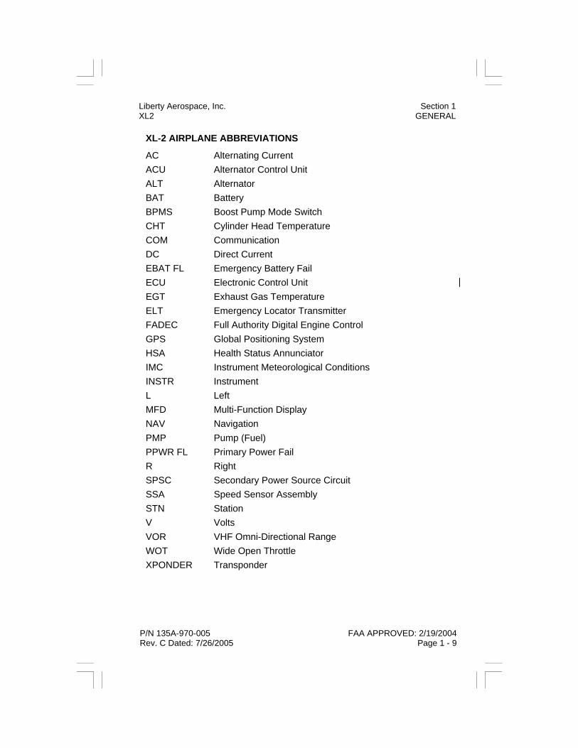
XL-2 AIRPLANE ABBREVIATIONS
AC Alternating Current ACU Alternator Control Unit ALT Alternator BAT Battery BPMS Boost Pump Mode Switch CHT Cylinder Head Temperature COM Communication DC Direct Current EBAT FL Emergency Battery Fail ECU Electronic Control Unit EGT Exhaust Gas Temperature ELT Emergency Locator Transmitter FADEC Full Authority Digital Engine Control GPS Global Positioning System HSA Health Status Annunciator IMC Instrument Meteorological Conditions INSTR Instrument L Left MFD Multi-Function Display NAV Navigation PMP Pump (Fuel) PPWR FL Primary Power Fail R Right SPSC Secondary Power Source Circuit SSA Speed Sensor Assembly STN Station V Volts VOR VHF Omni-Directional Range WOT Wide Open Throttle XPONDER Transponder
Liberty Aerospace, Inc. Section 1 XL2 GENERAL
P/N 135A-970-005 FAA APPROVED: 2/19/2004 Rev. C Dated: 7/26/2005 Page 1 - 9

Section 1 Liberty Aerospace, Inc. GENERAL XL2
FAA APPROVED: 2/19/2004 P/N 135A-970-005 Page 1 - 10 Initial Release
METEOROLOGICAL TERMINOLOGY
OAT - Outside Air Temperature is the free air static temperature. It may be expressed in either degrees Celsius or degrees Fahrenheit. Standard Temperature is 15° C at sea level pressure altitude and de-creases by 2° C for every 1000 feet of altitude. Pressure Altitude is the altitude read from an altimeter when the altime-ter’s barometric scale has been set to 29.92 in. Hg.(1013 mb). ENGINE POWER TERMINOLOGY
BHP Brake Horsepower - The power developed by the engine. RPM Revolutions per Minute - The rotational speed of the engine and propeller. Static RPM - The engine speed attained during a full throttle engine runup when the airplane is on the ground and stationary. psi - Pounds per square inch. AIRPLANE PERFORMANCE & FLIGHT PLANNING TERMINOLOGY
Demonstrated Crosswind Velocity - The velocity of the crosswind component for which adequate control of the airplane during takeoff and landing was actually demonstrated during certification test. The value shown is not considered to be limiting. Usable Fuel - The fuel available for flight planning. Unusable Fuel - The quantity of fuel that cannot be used in flight. Gallons Per Hour (GPH) - The amount of fuel consumed per hour in gallons. Feet Per Minute (fpm) - The distance in feet that can be traveled per minute. g - Acceleration expressed as a multiple of the earth’s normal gravity (1 g). WEIGHT AND BALANCE TERMINOLOGY
Reference Datum is an imaginary vertical plane from which all horizon-tal distances are measured for balance purposes.

Liberty Aerospace, Inc. Section 1 XL2 GENERAL
P/N 135A-970-005 FAA APPROVED: 2/19/2004 Initial Release Page 1 - 11
Station is a location along the airplane fuselage given in terms of dis-tance from the reference datum. Arm is the horizontal distance from the reference datum to the center of gravity (C.G.) of an item, or of the airplane as a whole. Moment is the product of the weight of an item, or of the airplane as a whole, multiplied by its arm. (Moment divided by a constant of 1000 is used in this manual to simplify calculations by reducing the number of digits, and is expressed as Moment/1000.) Center of Gravity (C.G.) is the point at which the airplane would bal-ance if suspended from that point. Its distance from the reference datum is determined by dividing the total moment by the total weight of the air-plane. C.G. Arm is the arm obtained by adding the airplane’s individual mo-ments and dividing the sum by the total weight. Center of Gravity Limits are the extreme center of gravity locations within which the airplane must be operated at a given weight. Standard Empty Weight is the weight of a standard airplane including unusable fuel, full operating fluids, and full engine oil. Basic Empty Weight is the standard empty weight plus the weight of optional equipment installed on a specific airplane. Useful Load is the difference between ramp weight and the basic empty weight. Mean Aerodynamic Chord (MAC) is the chord of an imaginary rectan-gular wing having the same pitching moments throughout the flight range as that of the actual wing. It may be determined by dividing the wing area by the wingspan. Maximum Ramp Weight is the maximum weight approved for ground maneuvers, and includes the weight of fuel used for start up, taxi, and run up. Maximum Takeoff Weight is the maximum weight approved for the start of the takeoff roll Maximum Landing Weight is the maximum weight approved for land-ing touchdown. Tare is the weight of chocks, blocks, stands, etc. used when weighing the airplane, and is included in the scale readings. Tare is deducted from scale readings to obtain actual (net) weight of the airplane.

Section 1 Liberty Aerospace, Inc. GENERAL XL2
FAA APPROVED: 2/19/2004 P/N 135A-970-005 Page 1 - 12 Initial Release
THIS PAGE INTENTIONALLY LEFT BLANK

P/N 135A-970-005 FAA APPROVED: 2/19/2004 Initial Release Page 2 - 1
Liberty Aerospace, Inc. Section 2 XL2 LIMITATIONS
SECTION 2
LIMITATIONS
TABLE OF CONTENTS
Introduction ............................................................................ 2 - 3 Airspeed Limitations............................................................... 2 - 4 Airspeed Indicator Markings .................................................. 2 - 4 Power Plant Limitations ......................................................... 2 - 5 Power Plant Instrument Markings.......................................... 2 - 6 Weight Limits ......................................................................... 2 - 6 Center of Gravity Limits ......................................................... 2 - 7 Maneuver Limits..................................................................... 2 - 8 Flight Load Factors ................................................................ 2 - 8 Kinds of Operation Limits....................................................... 2 - 8 Icing........................................................................................ 2 - 8 Fuel Limitations...................................................................... 2 - 8 Other Limitations.................................................................... 2 - 9 Placards ............................................................................... 2 - 10 Kinds of Operational Equipment List ................................... 2 - 15

Section 2 Liberty Aerospace, Inc. LIMITATIONS XL2
FAA APPROVED: 2/19/2004 P/N 135A-970-005 Page 2 - 2 Initial Release
THIS PAGE INTENTIONALLY LEFT BLANK

P/N 135A-970-005 FAA APPROVED: 2/19/2004 Initial Release Page 2 - 3
Liberty Aerospace, Inc. Section 2 XL2 LIMITATIONS
INTRODUCTION Section 2 includes operating limitations, instrument markings, and plac-ards necessary for the safe operation of the airplane, its engine, stan-dard systems, and standard equipment. The limitations included in this section and in Section 9 (Supplements) have been approved by the FAA. Observance of these limitations is required by the Federal Aviation Regulations (FAR).
NOTE Refer to Section 9 of this manual for amended operating limitations, operating procedures, performance data, or other information neces-sary for airplanes equipped with specific options.
The Liberty XL-2 airplane is certificated in the Normal Category under FAA Type Certificate No. A00008DE.
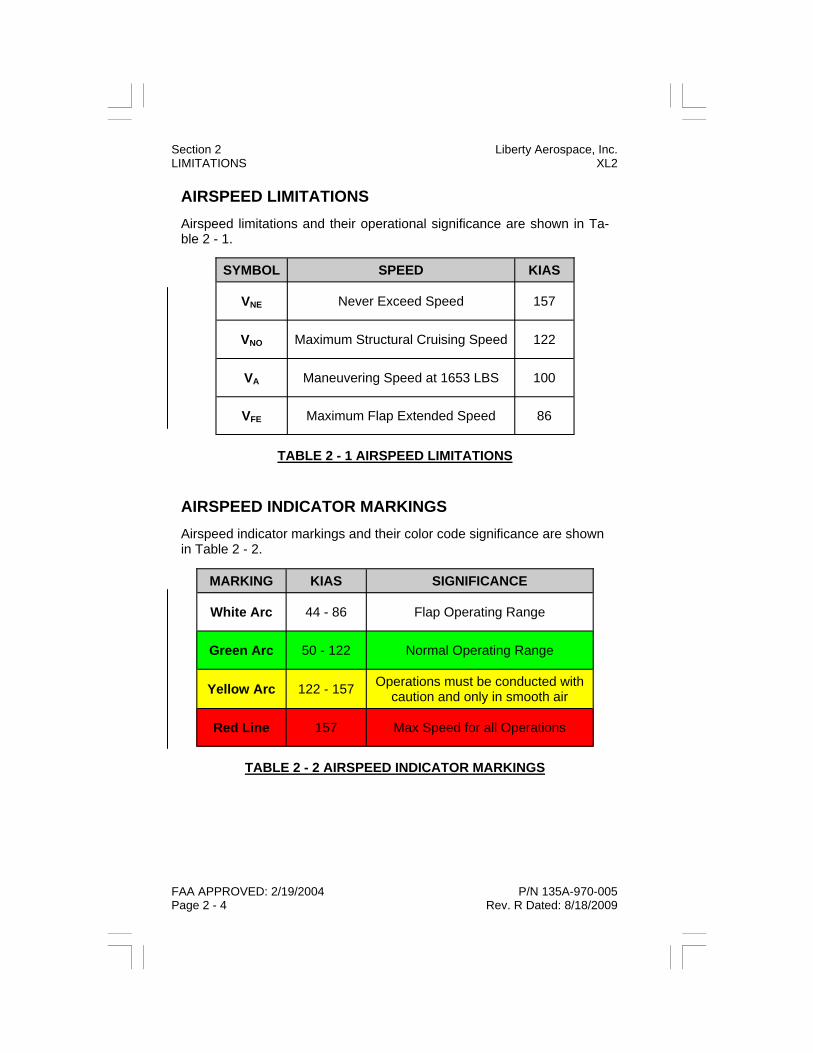
AIRSPEED LIMITATIONS Airspeed limitations and their operational significance are shown in Ta-ble 2 - 1.
AIRSPEED INDICATOR MARKINGS Airspeed indicator markings and their color code significance are shown in Table 2 - 2.
MARKING KIAS SIGNIFICANCE
White Arc 44 - 86 Flap Operating Range
Green Arc 50 - 122 Normal Operating Range
Yellow Arc 122 - 157 Operations must be conducted with caution and only in smooth air
Red Line 157 Max Speed for all Operations
TABLE 2 - 2 AIRSPEED INDICATOR MARKINGS
SYMBOL SPEED KIAS
VNE Never Exceed Speed 157
VNO Maximum Structural Cruising Speed 122
VA Maneuvering Speed at 1653 LBS 100
VFE Maximum Flap Extended Speed 86
TABLE 2 - 1 AIRSPEED LIMITATIONS
Section 2 Liberty Aerospace, Inc. LIMITATIONS XL2
FAA APPROVED: 2/19/2004 P/N 135A-970-005 Page 2 - 4 Rev. R Dated: 8/18/2009
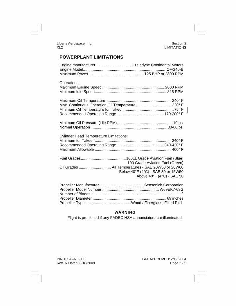
POWERPLANT LIMITATIONS Engine manufacturer ................................... Teledyne Continental Motors Engine Model.............................................................................IOF-240-B Maximum Power.................................................... 125 BHP at 2800 RPM Operations: Maximum Engine Speed ...........................................................2800 RPM Minimum Idle Speed....................................................................825 RPM Maximum Oil Temperature..............................................................240° F Max. Continuous Operation Oil Temperature .................................220° F Minimum Oil Temperature for Takeoff ..............................................75° F Recommended Operating Range.............................................170-200° F Minimum Oil Pressure (idle RPM).................................................... 10 psi Normal Operation ........................................................................30-60 psi Cylinder Head Temperature Limitations: Minimum for Takeoff........................................................................240° F Recommended Operating Range.............................................340-420° F Maximum Allowable ........................................................................460° F Fuel Grades..........................................100LL Grade Aviation Fuel (Blue) 100 Grade Aviation Fuel (Green) Oil Grades .............................. All Temperatures - SAE 20W50 or 20W60 Below 40°F (4°C) - SAE 30 or 15W50 Above 40°F (4°C) - SAE 50 Propeller Manufacturer..........................................Sensenich Corporation Propeller Model Number ..................................................... W69EK7-63G Number of Blades.....................................................................................2 Propeller Diameter ..................................................................... 69 inches Propeller Type ...........................................Wood / Fiberglass, Fixed Pitch
WARNING Flight is prohibited if any FADEC HSA annunciators are illuminated.
P/N 135A-970-005 FAA APPROVED: 2/19/2004 Rev. R Dated: 8/18/2009 Page 2 - 5
Liberty Aerospace, Inc. Section 2 XL2 LIMITATIONS

POWERPLANT INSTRUMENT MARKINGS Power plant instrument markings and their color code significance are shown in Table 2 - 3.
Instrument Red Line (MIN)
Green Arc (NORMAL)
Yellow Arc (CAUTION)
Red Line
(MAX)
Tachometer (rpm) - 850 - 2800 - 2800
Percent Power (%BHP) - 0 - 100 - 101
Oil Temp (°F) - 100 - 220 221 - 239 240
Oil Pressure (psi) 10 30 - 60 11 - 29 61 - 97 98
Cylinder Head Temp (°F) 240 240 - 420 421 - 459 460
Fuel Pressure (psi) 19 25 - 98 20 - 24 99
Exhaust Gas Temp (°F) - 1000 - 1675 - -
Manifold Pressure (In Hg) - 15.0 - 29.5 29.6 - 35.0 -
Ammeter (amps) - 0 - 48 49 - 59 60
Voltmeter (volts) 11.2 12.0 - 14.3 11.3 - 11.9 14.4 - 14.6 14.7
TABLE 2 - 3 POWERPLANT INSTRUMENT MARKINGS
Section 2 Liberty Aerospace, Inc. LIMITATIONS XL2
FAA APPROVED: 2/19/2004 P/N 135A-970-005 Page 2 - 6 Rev. B Dated: 11/24/2004

WEIGHT LIMITS Maximum ramp weight: 1653 lbs Maximum takeoff weight: 1653 lbs Maximum landing weight: 1653 lbs Maximum weight in baggage compartment: 100 lbs
WEIGHT AND CENTER OF GRAVITY LIMITS
Forward: 82.20 inches aft of datum at 1554 lbs. Mid: 83.48 inches aft of datum at 1653 lbs. Aft: 86.75 inches aft of datum at 1653 lbs.
The datum plane, Station 0.0 (STN 0.0) is located 70.75 inches forward of the vertical rollover hoop (edge of opening). See Figure 2 - 1 below.
FIGURE 2 - 1 LOCATION OF STATION 0.0
Liberty Aerospace, Inc. Section 2 XL2 LIMITATIONS
P/N 135A-970-005 FAA APPROVED: 2/19/2004 Rev. G Dated: 5/19/2006 Page 2 - 7

MANEUVER LIMITS This airplane is certified in the normal category, which is applicable to airplanes intended for non-aerobatic operations. These include maneu-vers incidental to normal flying, stalls, lazy eights, chandelles, and turns in which the angle of bank does not exceed 60 degrees. No aerobatic maneuvers, including spins, are authorized. Normal Category Maneuvers and Recommended Entry Speeds:
Chandelle: 100 KIAS Lazy Eight: 100 KIAS Steep Turn: 100 KIAS Stalls: Slow Deceleration
FLIGHT LOAD FACTORS
KINDS OF OPERATION LIMITS The Liberty XL-2 is equipped and approved for day/night VFR and IFR operations. ICING Flight into known icing conditions is prohibited. FUEL QUANTITY LIMITATIONS
Total fuel: 29.5 US Gallons Usable fuel (all flight conditions): 28 US Gallons Unusable fuel: 1.5 US Gallons
Operating Altitude Limitation Maximum Operating Altitude 12,500 ft
Load Factor Flaps Up Flaps Down
Positive 3.8 G 2.0 G
Negative -1.52 G 0.0 G
TABLE 2 - 3 FLIGHT LOAD FACTORS
Section 2 Liberty Aerospace, Inc. LIMITATIONS XL2
FAA APPROVED: 2/19/2004 P/N 135A-970-005 Page 2 - 8 Rev. R Dated: 8/18/2009

P/N 135A-970-005 FAA APPROVED: 2/19/2004 Initial Release Page 2 - 9
Liberty Aerospace, Inc. Section 2 XL2 LIMITATIONS
OTHER LIMITATIONS FLAP LIMITATIONS
Approved takeoff setting: 20° Performance data is presented for Flaps 20° only. Approved landing settings: 0°, 20°, 30° Performance data is presented for Flaps 30° only. No Intermediate flap settings are approved. SOLO FLIGHT LIMITATION
For optimal accessibility to emergency features (such as safety hammer, fire extinguisher, etc.) the aircraft must be flown solo from the left seat only.

PLACARDS The following information must be displayed in the form of panel overlay or individual placards: In full view of the pilot:
On the instrument panel, adjacent to the air speed indicator:
Adjacent to FADEC PWR A and B switches:
One each on the underside of fuselage next to the fuel drains:
On the underside of the fuselage next to the fuel tank vent:
THIS AIRPLANE MUST BE OPERATED IN ACCORDANCE WITH THE AIRPLANE FLIGHT MANUAL. THIS AIRPLANE IS CERTIFIED IN THE NORMAL CATEGORY AND APPROVED FOR VFR, IFR, DAY AND NIGHT IN NON-ICING CONDITIONS
WHEN EQUIPPED IN ACCORDANCE WITH FAR 91 OR FAR 135. NO ACROBATIC MANEUVERS, INCLUDING SPINS, APPROVED.
MANEUVERING SPEED VA = 100 KNOTS
FUEL DRAIN
FAA APPROVED: 2/19/2004 P/N 135A-970-005 Page 2 - 10 Rev. F Dated: 4/6/2006
Section 2 Liberty Aerospace, Inc. LIMITATIONS XL2
FUEL TANK VENT

On the VM1000 bottom bezel:
On center console:
Under top cowling, aft of firewall, next to hydraulic fluid reservoir:
Adjacent to magnetic compass:
On each door, under the canopy release lever (RED):
On exterior lower edge of both canopies, upside down facing out (RED):
One on each door, under the canopy release lever (RED):
NO SMOKING
P/N 135A-970-005 FAA APPROVED: 2/19/2004 Rev. R Dated: 8/18/2009 Page 2 - 11
Liberty Aerospace, Inc. Section 2 XL2 LIMITATIONS
Calibrated With Radio(s) ON For N 30 60 E 120 150 Steer For S 210 240 W 300 330 Steer Date

Vent panels are optional on aircraft. These placards are applicable only if vent panels are present (placard will be on both canopy vent windows (2 placards):
Above opening in back of starboard seat (RED):
Below opening in back of starboard seat:
Below both openings in back of seats
On forward side of baggage compartment closeout panel (2 placards):
FAA APPROVED: 2/19/2004 P/N 135A-970-005 Page 2 - 12 Rev. M Dated: 05/22/07
Section 2 Liberty Aerospace, Inc. LIMITATIONS XL2
ENSURE DOOR VENT PANEL IS CLOSED PRIOR TO OPERATING

On mid fuselage bulkhead behind the baggage compartment closeout panel:
On aft side of baggage compartment closeout panel adjacent to K001 & K002 relays:
On inside surface of port side fuselage, centered in view through lower rear access panel hole:
One each on exterior port and starboard doors adjacent to the canopy release lever (RED):
P/N 135A-970-005 FAA APPROVED: 2/19/2004 Rev. K Dated: 12/18/2006 Page 2 - 13
Liberty Aerospace, Inc. Section 2 XL2 LIMITATIONS
DO NOT REMOVE OR ADD TO
TAIL BALLAST WEIGHT

On exterior of fuselage around fuel filler cap: Below fuel filler cap on exterior of fuselage: Exterior, on both wing flaps and interior, on top surface of fuel filler hose cover inside the baggage area:
On either side of rudder, on both ailerons, and both elevators: Inside surface of oil filler door: Exterior port and starboard fuselage FWD of belly panel.
FAA APPROVED: 2/19/2004 P/N 135A-970-005 Page 2 - 14 Rev. P Dated: 04/18/2008
Section 2 Liberty Aerospace, Inc. LIMITATIONS XL2
KINDS OF OPERATION EQUIPMENT LIST The Liberty XL2 is equipped for day/night VFR and IFR operations.
Flight into known icing or forecast icing is prohibited.
The following equipment list identifies the systems and equipment upon which type certification for each kind of operation was predicated. This list does not include specific flight and radio/navigation equipment re-quired for any particular country’s operating regulations. The pilot-in-command is responsible for determining the airworthiness of the airplane and assuring compliance with current operating regulations for each flight.
The zeros used in the list below indicate that the system and/or equip-ment were not required for FAR Part 23 type certification for that kind of operation.
The ATA numbers refer to equipment classification of Air Transport As-sociation Specifications.
P/N 135A-970-005 FAA APPROVED: 2/19/2004 Rev. C Dated: 7/26/2005 Page 2 - 15
Liberty Aerospace, Inc. Section 2 XL2 LIMITATIONS

System, Instrument, and/or Equipment
VFR DAY
VFR NIGHT
IFR DAY
IFR NIGHT
KINDS OF OPERATION
COMMUNICATION (ATA-23)
Communications Radio (VHF) 0 * X X
ELECTRICAL POWER (ATA-24)
Battery (2) X X X X
Alternator X X X X
High Voltage/Discharge Warning Lights 0 0 0 0
Voltmeter X X X X
Ammeter X X X X
FLIGHT CONTROLS (ATA-27)
Flap System X X X X
Elevator Trim System X X X X
Elevator Trim Tab Indicator X X X X
Stall Warning Horn X X X X
Flap Indicator X X X X
FUEL (ATA-28)
Auxiliary Fuel Pump X X X X
Auxiliary Fuel Pump Switch X X X X
Auxiliary Fuel Pump Light X X X X
Fuel Quantity Indicator X X X X
Fuel Pressure Gauge 0 0 0 0
Fuel Selector Valve X X X X
FAA APPROVED: 2/19/2004 P/N 135A-970-005 Page 2 - 16 Rev. C Dated: 7/26/2005
Section 2 Liberty Aerospace, Inc. LIMITATIONS XL2
KINDS OF OPERATION System, Instrument, and/or Equipment
VFR DAY
VFR NIGHT
IFR DAY
IFR NIGHT
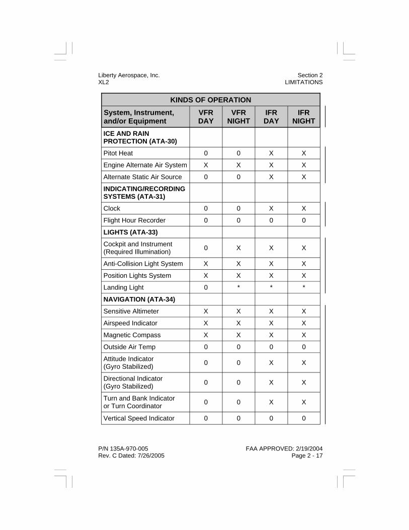
ICE AND RAIN PROTECTION (ATA-30)
Pitot Heat 0 0 X X
Engine Alternate Air System X X X X
Alternate Static Air Source 0 0 X X
INDICATING/RECORDING SYSTEMS (ATA-31)
Clock 0 0 X X
Flight Hour Recorder 0 0 0 0
LIGHTS (ATA-33)
Cockpit and Instrument (Required Illumination) 0 X X X
Anti-Collision Light System X X X X
Position Lights System X X X X
Landing Light 0 * * *
NAVIGATION (ATA-34)
Sensitive Altimeter X X X X
Airspeed Indicator X X X X
Magnetic Compass X X X X
Outside Air Temp 0 0 0 0
Attitude Indicator (Gyro Stabilized) 0 0 X X
Directional Indicator (Gyro Stabilized) 0 0 X X
Turn and Bank Indicator or Turn Coordinator 0 0 X X
Vertical Speed Indicator 0 0 0 0
P/N 135A-970-005 FAA APPROVED: 2/19/2004 Rev. C Dated: 7/26/2005 Page 2 - 17
Liberty Aerospace, Inc. Section 2 XL2 LIMITATIONS

* Ref. §91.205
KINDS OF OPERATION System, Instrument, and/or Equipment
VFR DAY
VFR NIGHT
IFR DAY
IFR NIGHT
Navigation Radio (VHF) 0 * X X
Pitot Static System X X X X
ENGINE INDICATING (ATA-77)
FADEC Health Status Annunciator (HSA) X X X X
Tachometer Indicator (Propeller) X X X X
Manifold Pressure Indicator 0 0 0 0
Cylinder Head Temp X X X X
Alt Fail Annunciator X X X X
ENGINE OIL (ATA-79)
Oil Temperature Indicator X X X X
Oil Pressure Indicator X X X X
Oil Quantity Indicator (Dipstick) X X X X
EQUIPMENT/FURNISHINGS (ATA-25)
Lap and Shoulder Safety Restraints (each occupant) X X X X
Fire Extinguisher X X X X
Emergency Safety Hammer X X X X
ELT X X X X
Airplane Flight Manual X X X X
Windscreen Demist Cloth 0 0 X X
Cargo Net Restraint 0 0 0 0
FAA APPROVED: 2/19/2004 P/N 135A-970-005 Page 2 - 18 Rev. C Dated: 7/26/2005
Section 2 Liberty Aerospace, Inc. LIMITATIONS XL2
SECTION 3
EMERGENCY PROCEDURES
TABLE OF CONTENTS
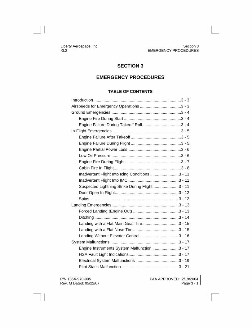
Introduction.............................................................................3 - 3 Airspeeds for Emergency Operations ....................................3 - 3 Ground Emergencies..............................................................3 - 4 Engine Fire During Start ..................................................3 - 4 Engine Failure During Takeoff Roll..................................3 - 4 In-Flight Emergencies ............................................................3 - 5 Engine Failure After Takeoff ............................................3 - 5 Engine Failure During Flight ............................................3 - 5 Engine Partial Power Loss...............................................3 - 6 Low Oil Pressure..............................................................3 - 6 Engine Fire During Flight .................................................3 - 7 Cabin Fire In Flight...........................................................3 - 8 Inadvertent Flight Into Icing Conditions .........................3 - 11 Inadvertent Flight Into IMC.............................................3 - 11 Suspected Lightning Strike During Flight.......................3 - 11 Door Open In Flight........................................................3 - 12 Spins ..............................................................................3 - 12 Landing Emergencies...........................................................3 - 13 Forced Landing (Engine Out) ........................................3 - 13 Ditching ..........................................................................3 - 14 Landing with a Flat Main Gear Tire................................3 - 15 Landing with a Flat Nose Tire ........................................3 - 15 Landing Without Elevator Control ..................................3 - 16 System Malfunctions ............................................................3 - 17 Engine Instruments System Malfunction .......................3 - 17 HSA Fault Light Indications............................................3 - 17 Electrical System Malfunctions ......................................3 - 19 Pitot Static Malfunction ..................................................3 - 21
Liberty Aerospace, Inc. Section 3 XL2 EMERGENCY PROCEDURES
P/N 135A-970-005 FAA APPROVED: 2/19/2004 Rev. M Dated: 05/22/07 Page 3 - 1

Section 3 Liberty Aerospace, Inc. EMERGENCY PROCEDURES XL2
FAA APPROVED: 2/19/2004 P/N 135A-970-005 Page 3 - 2 Initial Release
THIS PAGE INTENTIONALLY LEFT BLANK

Liberty Aerospace, Inc. Section 3 XL2 EMERGENCY PROCEDURES
P/N 135A-970-005 FAA APPROVED: 2/19/2004 Initial Release Page 3 - 3
INTRODUCTION Section 3 provides checklists and amplified procedures for emergencies that may occur. Emergencies caused by malfunctions are extremely rare if proper maintenance and preflight inspection procedures are ob-served. Enroute and weather emergencies can be minimized by careful and conservative preflight planning and good judgment.
Warnings and procedures depicted in this AFM are immediate action or “memory items.” They should be committed to memory so that they can be performed immediately without reference to the checklist.
The phrase “land as soon as practical” means that flight may be contin-ued to the next available airport, depending on weather conditions, the severity of the emergency, etc.
The phrase “land as soon as possible” means that a landing should be accomplished immediately or as rapidly as possible consistent with safety requirements. Depending on weather conditions, the severity of the emergency, etc., the pilot-in-command may elect to make this land-ing on a nearby suitable surface on which the airplane may be landed safely, even if this location is not on an airport.
Emergency procedures associated with avionics, and the ELT are found in Section 9.
AIRSPEEDS FOR EMERGENCY OPERATIONS Maneuvering Speed: 1653 lbs ......................................................................... 100 KIAS 1450 lbs ........................................................................... 94 KIAS
Best Glide Speed: 1653 lbs ........................................................................... 80 KIAS
Emergency Approach Speed Without Engine Power: Flaps Up .......................................................................... 70 KIAS Flaps 30° ......................................................................... 65 KIAS

Section 3 Liberty Aerospace, Inc. EMERGENCY PROCEDURES XL2
FAA APPROVED: 2/19/2004 P/N 135A-970-005 Page 3 - 4 Initial Release
GROUND EMERGENCIES ENGINE FIRE DURING START
1. Ignition Switch ......................................................................... START Continue turning the engine over in attempt to obtain successful start that will suck flame and accumulated fuel into engine.
If engine starts: 2. Power ................. 1700 RPM (for up to 2 minutes, if conditions allow) 3. Engine .........................................SHUT DOWN (inspect for damage) If engine does NOT start: 4. Ignition Switch ......................................................................... START 5. Throttle ....................................................................FULL FORWARD 6. FADEC A and B PWR Switches...................................................OFF 7. Fuel Selector Valve ......................................OFF (lift knob to turn off) 8. Cranking ......................................................................... TERMINATE 9. Ignition Switch ..............................................................................OFF 10. Master Switch...............................................................................OFF 11. Airplane ............................................................................EVACUATE 12. Fire ......................EXTINGUISH (use fire extinguisher as necessary) 13. Fire Damage........................................................................ INSPECT ENGINE FAILURE DURING TAKEOFF ROLL
(Aborted Takeoff Procedure) 1. Throttle ........................................................................................ IDLE 2. Brakes ..................................................................................... APPLY After aircraft stops: 3. Ignition Switch ..............................................................................OFF 4. FADEC A and B PWR Switches...................................................OFF 5. Master Switch...............................................................................OFF 6. Fuel Selector Valve ......................................OFF (lift knob to turn off)

Liberty Aerospace, Inc. Section 3 XL2 EMERGENCY PROCEDURES
P/N 135A-970-005 FAA APPROVED: 2/19/2004 Initial Release Page 3 - 5
IN-FLIGHT EMERGENCIES ENGINE FAILURE AFTER TAKEOFF
1. Best Glide or Landing Speed (as appropriate) ................ESTABLISH 2. Flaps ...........................................................................AS REQUIRED If time permits: 3. Ignition Switch.............................................................................. OFF 4. FADEC A and B PWR Switches .................................................. OFF 5. Master Switch .............................................................................. OFF 6. Throttle.........................................................................................IDLE 7. Fuel Selector Valve...................................... OFF (lift knob to turn off) 8. Seat Belts and Shoulder Harness.........................................SECURE ENGINE FAILURE DURING FLIGHT
(Troubleshoot/Restart Procedure) If the engine fails at altitude, the primary task is to maintain control of the airplane and establish best glide speed while turning toward a suitable landing area. Only after this has been accomplished should the pilot attempt to determine the cause of engine failure, and if time and altitude permit, attempt a restart.
Restart attempts should not be performed if they distract the pilot from the primary task of flying the airplane at best glide speed to a suitable landing area. Restart attempts should be abandoned in sufficient time to allow completion of the forced landing checklist.
1. Best Glide Speed.............................................................ESTABLISH 2. Fuel Selector Valve...........................................................CHECK ON 3. Throttle...................................................................... OPEN 3/4 INCH 4. Fuel Boost Pump Mode Switch...................................................... ON 5. FADEC A and B PWR Switches .......RECYCLE SIMULTANEOUSLY 6. Ignition Switch..............................................................CHECK BOTH 7. Ignition Switch (if prop NOT windmilling) .................................START 8. Throttle.............. ADJUST TO OBTAIN BEST ENGINE OPERATION 9. Repeat steps 2 - 6 as necessary with prop windmilling. 10. In engine does not start, perform Forced Landing checklist.
Section 3 Liberty Aerospace, Inc. EMERGENCY PROCEDURES XL2
FAA APPROVED: 2/19/2004 P/N 135A-970-005 Page 3 - 6 Initial Release
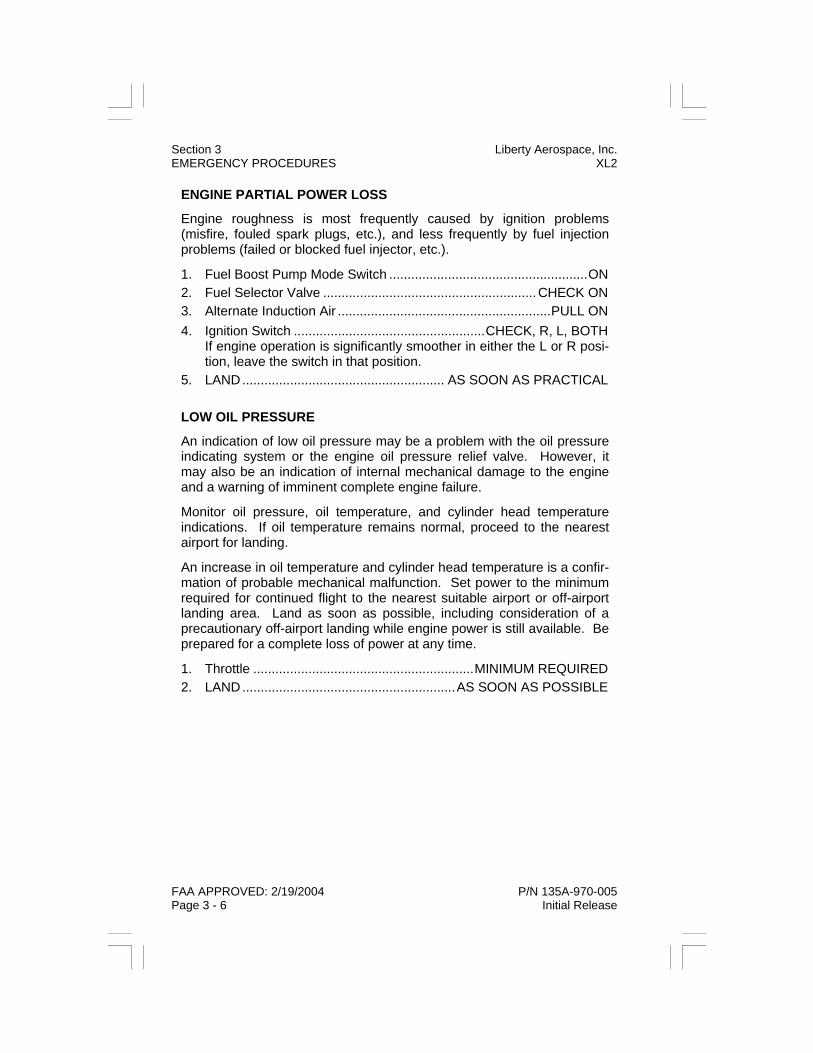
ENGINE PARTIAL POWER LOSS
Engine roughness is most frequently caused by ignition problems (misfire, fouled spark plugs, etc.), and less frequently by fuel injection problems (failed or blocked fuel injector, etc.).
1. Fuel Boost Pump Mode Switch ......................................................ON 2. Fuel Selector Valve ..........................................................CHECK ON 3. Alternate Induction Air ..........................................................PULL ON 4. Ignition Switch ....................................................CHECK, R, L, BOTH
If engine operation is significantly smoother in either the L or R posi-tion, leave the switch in that position.
5. LAND....................................................... AS SOON AS PRACTICAL LOW OIL PRESSURE
An indication of low oil pressure may be a problem with the oil pressure indicating system or the engine oil pressure relief valve. However, it may also be an indication of internal mechanical damage to the engine and a warning of imminent complete engine failure.
Monitor oil pressure, oil temperature, and cylinder head temperature indications. If oil temperature remains normal, proceed to the nearest airport for landing.
An increase in oil temperature and cylinder head temperature is a confir-mation of probable mechanical malfunction. Set power to the minimum required for continued flight to the nearest suitable airport or off-airport landing area. Land as soon as possible, including consideration of a precautionary off-airport landing while engine power is still available. Be prepared for a complete loss of power at any time.
1. Throttle ............................................................MINIMUM REQUIRED 2. LAND..........................................................AS SOON AS POSSIBLE
Liberty Aerospace, Inc. Section 3 XL2 EMERGENCY PROCEDURES
P/N 135A-970-005 FAA APPROVED: 2/19/2004 Initial Release Page 3 - 7
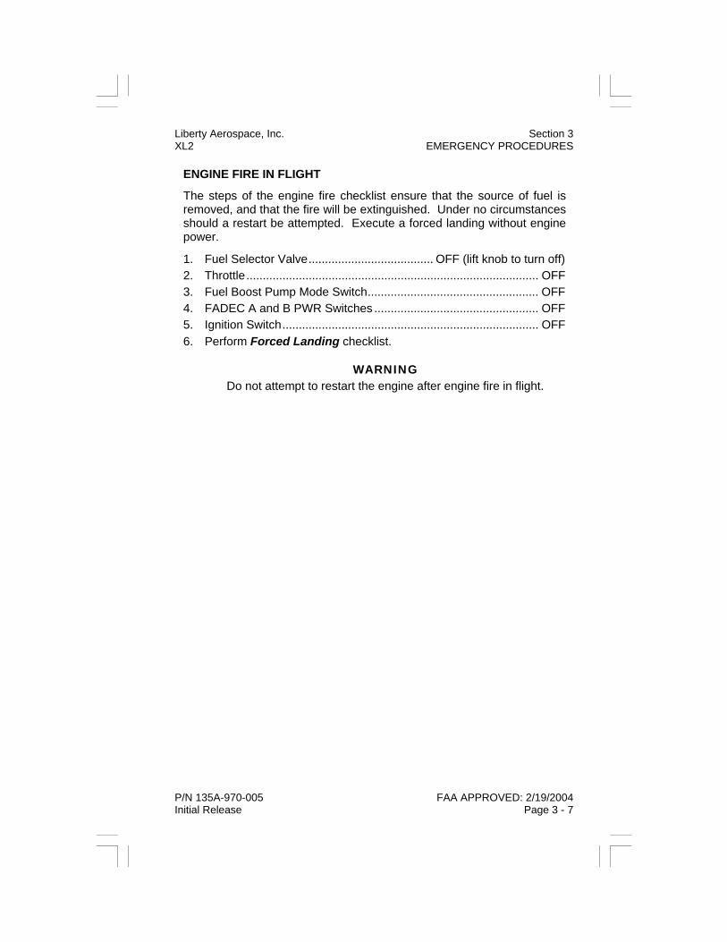
ENGINE FIRE IN FLIGHT
The steps of the engine fire checklist ensure that the source of fuel is removed, and that the fire will be extinguished. Under no circumstances should a restart be attempted. Execute a forced landing without engine power.
1. Fuel Selector Valve...................................... OFF (lift knob to turn off) 2. Throttle......................................................................................... OFF 3. Fuel Boost Pump Mode Switch.................................................... OFF 4. FADEC A and B PWR Switches .................................................. OFF 5. Ignition Switch.............................................................................. OFF 6. Perform Forced Landing checklist.
WARNING Do not attempt to restart the engine after engine fire in flight.

Section 3 Liberty Aerospace, Inc. EMERGENCY PROCEDURES XL2
FAA APPROVED: 2/19/2004 P/N 135A-970-005 Page 3 - 8 Initial Release
CABIN FIRE IN FLIGHT
If the cause of the fire is readily apparent and accessible, use the fire extinguisher mounted in the headrest compartment behind the passen-ger seat to extinguish flames and land as soon as practical. Opening the vents may feed the fire, but to avoid incapacitating the crew from smoke inhalation, it may be necessary to rid the cabin of smoke. If the cause of fire is not readily apparent, is electrical, or is not readily acces-sible, perform the following:
NOTE Electrical power is required for engine operation. Improper opera-tion of electrical switches may cause immediate engine stoppage. Two independent sources of electrical power are provided for engine operation. It is important to understand their interactions. Details are provided in Section 7 - Airplane & Systems Description.
1. Master Switch...............................................................................OFF
If engine loses power after master switch is turned OFF, Master Switch ON immediately and refer to Step 22.
WARNING HSA EBAT FL and PPWR FL annunciators will illuminate. Engine may continue to operate normally from the emergency battery for up to 60 minutes if the battery is properly maintained and fully charged. Plan to land well within 60 minutes from illumination of EBAT FL and PPWR FL annunciators.
2. FADEC PWR A Switch.................................................................OFF 3. Avionics Master Switch ................................................................OFF 4. All Electrical Switches ...............OFF (except FADEC PWR B switch)
WARNING Turning off FADEC PWR B switch when Master Switch is OFF will cause immediate loss of engine power.
5. Fire Extinguisher ............................................................... ACTIVATE 6. Air Vents ....................................................... OPEN TO VENT CABIN 7. LAND....................................................... AS SOON AS PRACTICAL
Liberty Aerospace, Inc. Section 3 XL2 EMERGENCY PROCEDURES
P/N 135A-970-005 FAA APPROVED: 2/19/2004 Initial Release Page 3 - 9
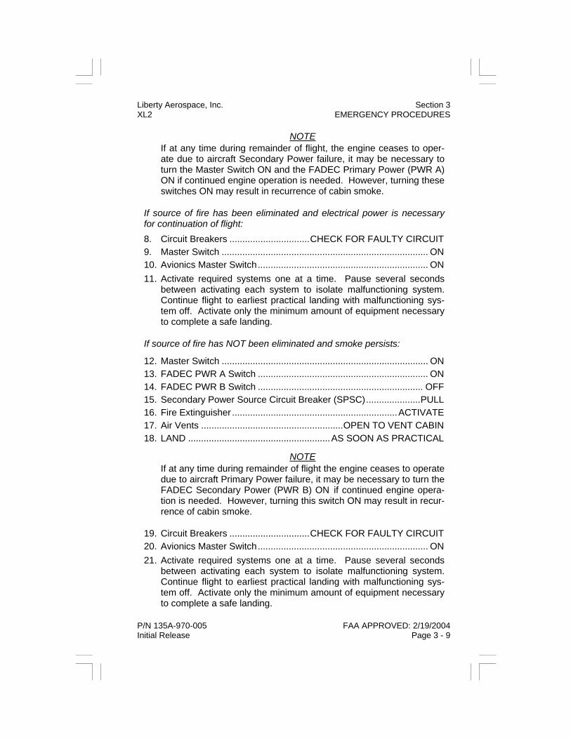
NOTE If at any time during remainder of flight, the engine ceases to oper-ate due to aircraft Secondary Power failure, it may be necessary to turn the Master Switch ON and the FADEC Primary Power (PWR A) ON if continued engine operation is needed. However, turning these switches ON may result in recurrence of cabin smoke.
If source of fire has been eliminated and electrical power is necessary for continuation of flight: 8. Circuit Breakers ...............................CHECK FOR FAULTY CIRCUIT 9. Master Switch ................................................................................ ON 10. Avionics Master Switch.................................................................. ON 11. Activate required systems one at a time. Pause several seconds
between activating each system to isolate malfunctioning system. Continue flight to earliest practical landing with malfunctioning sys-tem off. Activate only the minimum amount of equipment necessary to complete a safe landing.
If source of fire has NOT been eliminated and smoke persists:
12. Master Switch ................................................................................ ON 13. FADEC PWR A Switch .................................................................. ON 14. FADEC PWR B Switch ................................................................ OFF 15. Secondary Power Source Circuit Breaker (SPSC).....................PULL 16. Fire Extinguisher ................................................................ACTIVATE 17. Air Vents .......................................................OPEN TO VENT CABIN 18. LAND .......................................................AS SOON AS PRACTICAL
NOTE If at any time during remainder of flight the engine ceases to operate due to aircraft Primary Power failure, it may be necessary to turn the FADEC Secondary Power (PWR B) ON if continued engine opera-tion is needed. However, turning this switch ON may result in recur-rence of cabin smoke.
19. Circuit Breakers ...............................CHECK FOR FAULTY CIRCUIT 20. Avionics Master Switch.................................................................. ON 21. Activate required systems one at a time. Pause several seconds
between activating each system to isolate malfunctioning system. Continue flight to earliest practical landing with malfunctioning sys-tem off. Activate only the minimum amount of equipment necessary to complete a safe landing.
Section 3 Liberty Aerospace, Inc. EMERGENCY PROCEDURES XL2
FAA APPROVED: 2/19/2004 P/N 135A-970-005 Page 3 - 10 Initial Release
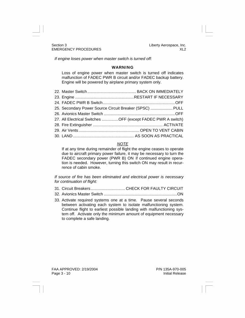
If engine loses power when master switch is turned off:
WARNING Loss of engine power when master switch is turned off indicates malfunction of FADEC PWR B circuit and/or FADEC backup battery. Engine will be powered by airplane primary system only.
22. Master Switch............................................ BACK ON IMMEDIATELY 23. Engine .....................................................RESTART IF NECESSARY 24. FADEC PWR B Switch.................................................................OFF 25. Secondary Power Source Circuit Breaker (SPSC) .................... PULL 26. Avionics Master Switch ................................................................OFF 27. All Electrical Switches ...............OFF (except FADEC PWR A switch) 28. Fire Extinguisher ............................................................... ACTIVATE 29. Air Vents ....................................................... OPEN TO VENT CABIN 30. LAND....................................................... AS SOON AS PRACTICAL
NOTE If at any time during remainder of flight the engine ceases to operate due to aircraft primary power failure, it may be necessary to turn the FADEC secondary power (PWR B) ON if continued engine opera-tion is needed. However, turning this switch ON may result in recur-rence of cabin smoke.
If source of fire has been eliminated and electrical power is necessary for continuation of flight:
31. Circuit Breakers............................... CHECK FOR FAULTY CIRCUIT 32. Avionics Master Switch ..................................................................ON 33. Activate required systems one at a time. Pause several seconds
between activating each system to isolate malfunctioning system. Continue flight to earliest possible landing with malfunctioning sys-tem off. Activate only the minimum amount of equipment necessary to complete a safe landing.
INADVERTENT FLIGHT INTO ICING CONDITIONS
Flight into known or forecast icing conditions is prohibited. However, if an inadvertent encounter with icing conditions occurs:
1. Maneuver ........................TURN 180° AND/OR CHANGE ALTITUDE (to exit icing conditions as soon as possible) 2. Alternate Induction Air.......................................................... PULL ON INADVERTENT FLIGHT INTO INSTRUMENT METEOROLOGICAL CONDITONS
If Instrument Meteorological Conditions (IMC) are inadvertently encoun-tered, maintain control of the airplane by reference to flight instruments and perform the following:
1. Airplane Control .. INITIALLY ESTABLISH STRAIGHT & LEVEL FLIGHT 2. Standard Rate Turn ..................................INITIATE AND TURN 180° SUSPECTED LIGHTNING STRIKE DURING FLIGHT
Flight through or in the vicinity of thunderstorms is not recommended under any circumstances. However, if it is suspected that the aircraft has been hit by lightning, perform the following:
1. Airspeed........................................................... REDUCE TO 80 KIAS (exit thunderstorm conditions as soon as possible) 2. LAND .......................................................AS SOON AS PRACTICAL
Liberty Aerospace, Inc. Section 3 XL2 EMERGENCY PROCEDURES
P/N 135A-970-005 FAA APPROVED: 2/19/2004 Rev. C Dated: 7/26/2005 Page 3 - 11
Section 3 Liberty Aerospace, Inc. EMERGENCY PROCEDURES XL2
FAA APPROVED: 2/19/2004 P/N 135A-970-005 Page 3 - 12 Initial Release
DOOR OPEN IN FLIGHT
Abort takeoff if door opens during takeoff. In flight, do not allow efforts to re-close the door to interfere with the primary task of maintaining con-trol and flying the airplane.
1. Airspeed ................................................... REDUCE TO 80 - 90 KIAS 2. Door................................................................... CLOSE AND LATCH (yaw airplane in direction of open door if necessary) 3. Approach Speed...................................................................NORMAL
If unable to latch door in flight, or if damage has occurred: 4. LAND....................................................... AS SOON AS PRACTICAL SPINS
If an inadvertent spin occurs, use the following recovery procedure:
1. Throttle ........................................................................................ IDLE 2. Ailerons............................................................................... NEUTRAL 3. Rudder....................................... APPLY AND HOLD FULL RUDDER (opposite direction of rotation) 4. After Rudder Application ........................... MOVE STICK FORWARD
(to break stalled condition, at aft C.G. locations, full forward stick may be required)
5. Neutralize Rudder ....................................MAKE SMOOTH PULL-UP FROM THE RESULTING DIVE 6. Throttle ................... ADJUST FOR STRAIGHT AND LEVEL FLIGHT
NOTE If disorientation makes determining direction of rotation difficult, refer to the turn coordinator. It will be fully deflected in the direction of rotation.

Liberty Aerospace, Inc. Section 3 XL2 EMERGENCY PROCEDURES
P/N 135A-970-005 FAA APPROVED: 2/19/2004 Initial Release Page 3 - 13
LANDING EMERGENCIES FORCED LANDING (Engine Out)
If restart attempts have failed and a forced landing is unavoidable, select a suitable field and prepare to land as described in the Forced Landing (Engine Out) checklist. If time and altitude permits, transmit a Mayday message on 121.5 mHz and set the transponder, if installed, to code 7700. Complete the checklist items to minimize the risk of fire after land-ing. Before a forced landing, particularly in rough or mountainous ter-rain, it is good safety practice to manual activate the ELT.
Plan to touch down approximately one third the way into the available landing distance. Far less damage and risk of injury will result from overrunning the far end of the field at low speed on the ground than from potentially stalling into or short of the near end of the field at high speed while still airborne.
1. Best Glide Speed.............................................................ESTABLISH 2. Radio............................................TRANSMIT (121.5 mHz) MAYDAY (giving location and intentions) 3. Transponder................................................................SQUAWK 7700 4. ELT (if off airport) ...............................................................ACTIVATE 5. Ignition Switch.............................................................................. OFF 6. FADEC A and B PWR Switches .................................................. OFF 7. Fuel Boost Pump Mode Switch.................................................... OFF 8. Throttle.........................................................................................IDLE 9. Fuel Selector Valve...................................OFF (lift knob to turn OFF) 10. Flaps (when field is made).............................AS REQUIRED OR 30° 11. Master Switch .............................................................................. OFF 12. Seat Belts and Shoulder Harness.........................................SECURE
WARNING Flaps will not operate when Master Switch is OFF. Do not turn the Master Switch OFF until after flaps have been set to their final de-sired position and the landing is assured.

Section 3 Liberty Aerospace, Inc. EMERGENCY PROCEDURES XL2
FAA APPROVED: 2/19/2004 P/N 135A-970-005 Page 3 - 14 Initial Release
DITCHING
1. Best Glide Speed ............................................................ ESTABLISH 2. Radio ........................................... TRANSMIT (121.5 mHz) MAYDAY (giving location and intentions) 3. Transponder ...............................................................SQUAWK 7700 4. ELT .................................................................................... ACTIVATE 5. Loose Objects....................................................SECURE (if possible) 6. Seat Belts and Shoulder Harness ........................................ SECURE 7. Flaps...............................................................................................30° 8. Power ........................ ESTABLISH 300 FPM DESCENT AT 65 KIAS 9. Approach ..........................................................................INTO WIND (for high winds and heavy seas) 10. Approach ..................................................... PARALLEL TO SWELLS (for light winds, heavy swells) 11. Touchdown............................................................ LEVEL ATTITUDE
(At established rate of descent; avoid an excessive nose-high atti-tude to prevent stalling into water.)
12. Airplane ............................................................................EVACUATE (Through canopy doors. If necessary, open vent windows to flood cabin and equalize pressure to allow doors to be opened. Use safety hammer if necessary.)
13. Life Vests and Life Raft (if available).................................... INFLATE (when clear of airplane)
NOTE If no engine power is available, approach at 70 KIAS with flaps UP or 65 KIAS with flaps at 30°.

Liberty Aerospace, Inc. Section 3 XL2 EMERGENCY PROCEDURES
P/N 135A-970-005 FAA APPROVED: 2/19/2004 Initial Release Page 3 - 15
LANDING WITH A FLAT MAIN GEAR TIRE
1. Approach Speed .................................................................. NORMAL 2. Line Up....................ON SIDE OF RUNWAY OPPOSITE FLAT TIRE (Airplane will tend to turn toward flat tire after touchdown.) 3. Flaps .............................................................................................. 30° 4. Touchdown ...................................... GOOD SIDE MAIN TIRE FIRST (Hold airplane off flat tire as long as possible using ailerons.) 5. Directional Control ............................................................. MAINTAIN (Using rudder and brake on good tire side as required.) LANDING WITH A FLAT NOSE TIRE
CAUTION Do not attempt to taxi airplane with flat main or nose gear tire.
1. Approach Speed .................................................................. NORMAL 2. Flaps ...........................................................................AS REQUIRED 3. Touchdown ...............................................................ON MAIN GEAR (Hold nose wheel off the ground as long as possible) 4. Elevator.................................................MAINTAIN FULL AFT STICK (After nose wheel touches down) 5. Brakes.....................................................USE MINIMUM REQUIRED 6. Ignition Switch.............................................................................. OFF (If operational considerations permit)

Section 3 Liberty Aerospace, Inc. EMERGENCY PROCEDURES XL2
FAA APPROVED: 2/19/2004 P/N 135A-970-005 Page 3 - 16 Initial Release
LANDING WITHOUT ELEVATOR CONTROL
Manipulating the electric pitch trim and throttle provides attitude control should primary elevator control be lost. Make small adjustments to trim and throttle to adjust pitch attitude and airspeed for best glide angle for landing.
Choose the longest available runway. The final power reduction after the landing flare will cause a nose-down pitch and a possible nose wheel first touchdown. Make a gradual power reduction while simultane-ously selecting nose-up elevator trim.
1. Throttle .................................................................................REDUCE 2. Trim ............................................................NOSE UP, SLOW TO VFE 3. Flaps..................................................................GRADUALLY TO 20° 4. Approach Speed............................ 75 KIAS, USE TRIM TO ADJUST 5. Throttle ..................................... AS REQUIRED FOR GLIDE ANGLE

SYSTEM MALFUNCTIONS ENGINE INSTRUMENT SYSTEM MALFUNCTION
A blanking of the engine instruments display may indicate a malfunction of the engine instruments system. Blanking of the engine instruments system will not affect engine performance or continued engine opera-tion. FADEC control of the engine is unaffected by the engine instru-ment system status. The FADEC HSA system will continue to provide the pilot with engine health and status information for continued flight to the nearest suitable airport. Refer to the HSA Fault Light Indications section of this manual as required to determine engine status. 1. FADEC HSA .......................................................................MONITOR 2. Throttle ...........................................................MINIMUM REQUIRED 3. LAND ....................................................... AS SOON AS PRACTICAL HSA FAULT LIGHT INDICATIONS Both HSA “EBAT FL” and “PPWR FL” Annunciators Illuminated 1. FADEC PWR A and B Switches.......................................CHECK ON 2. FADEC PWR A and B Circuit Breakers .............................CHECK IN If annunciators remain ON: 3. LAND ....................................................... AS SOON AS PRACTICAL
WARNING Engine may continue to operate normally from the emergency bat-tery for up to 60 minutes if the emergency battery is properly main-tained and fully charged. Plan to land well within 60 minutes from illumination of EBAT FL and PPWR FL annunciators.
HSA “EBAT FL” Annunciator ONLY Illuminated 1. FADEC PWR B Switch.....................................................CHECK ON 2. FADEC PWR B Circuit Breakers........................................CHECK IN If annunciator remains illuminated: 3. LAND ....................................................... AS SOON AS PRACTICAL
WARNING Illumination of only the EBAT FL annunciator may indicate failure of the emergency battery. Should the alternator also fail, the engine will only be powered by the primary battery, which is also affected by other electrical loads.
P/N 135A-970-005 FAA APPROVED: 2/19/2004 Rev. M Dated: 05/22/07 Page 3 -17
Liberty Aerospace, Inc. Section 3 XL2 EMERGENCY PROCEDURES

HSA Red “FADEC WARN” Annunciator Illuminated 1. Ignition Switch..............................................................CHECK BOTH 2. Engine Instruments.............................................................MONITOR 3. LAND .......................................................AS SOON AS PRACTICAL
WARNING Illumination of the red FADEC WARN annunciator light is to be treated as a potential for partial or total loss of engine power - critical condition with imminent partial or total loss of engine power.
HSA Yellow “FADEC CAUTION” Annunciator Illuminated 1. FADEC PWR A and B Switches.......................................CHECK ON 2. Ignition Switch..............................................................CHECK BOTH 3. Engine Instruments.............................................................MONITOR If condition or annunciation persists: 4. LAND .......................................................AS SOON AS PRACTICAL
WARNING Illumination of the yellow FADEC CAUTION annunciator indicates a fault in the FADEC system has occurred. A second fault could result in partial or total loss of engine power.
HSA “FUEL PMP” Annunciator Illuminated In Flight The FUEL PMP annunciator will illuminate anytime the Fuel Boost Pump Mode Switch is moved from the AUTO position. If the FUEL PMP an-nunciator is illuminated with the Fuel Boost Pump Mode Switch in the AUTO position, it may indicate engine driven fuel pump failure.
1. Fuel Boost Pump Mode Switch....................................CHECK AUTO 2. Fuel Pressure Gauge..........................................................MONITOR If condition or annunciation persists: 3. Fuel Boost Pump Mode Switch...................................................... ON 4. Fuel Pressure Gauge..........................................................MONITOR 5. LAND ....................................................... AS SOON AS PRACTICAL
FAA APPROVED: 2/19/2004 P/N 135A-970-005 Page 3 - 18 Rev. C Dated: 7/26/2005
Section 3 Liberty Aerospace, Inc. EMERGENCY PROCEDURES XL2

Liberty Aerospace, Inc. Section 3 XL2 EMERGENCY PROCEDURES
P/N 135A-970-005 FAA APPROVED: 2/19/2004 Initial Release Page 3 - 19
ELECTRICAL SYSTEM MALFUNCTIONS
Ammeter Abnormally High 1. Alternator Side (ONLY) of Master Switch OFF 2. Non-essential Electrical Equipment OFF 3. LAND AS SOON AS PRACTICAL
WARNING After loss or shutdown of alternator, EBAT FL and PPWR FL annun-ciators may illuminate. Engine may continue to operate normally from the emergency battery for up to 60 minutes if the battery is properly maintained and fully charged. Plan to land well within 60 minutes from illumination of EBAT FL and PPWR FL annunciators.
Voltmeter Abnormally Low In Flight 1. Non-essential Electrical Equipment OFF 2. Perform “ALT FAIL” Annunciator Illuminated In Flight checklist.
Voltmeter In Red Arc In Flight 1. LAND AS SOON AS PRACTICAL
Section 3 Liberty Aerospace, Inc. EMERGENCY PROCEDURES XL2
FAA APPROVED: 2/19/2004 P/N 135A-970-005 Page 3 - 20 Initial Release
“ALT FAIL” Annunciator Illuminated In Flight Illumination of the ALT FAIL annunciator in flight can result either from alternator failure or from alternator “tripping offline” due to momentary over voltage. The following procedure should reset the alternator sys-tem.
1. Ammeter .......................................................... CHECK FOR 0 AMPS 2. Alternator Side of Master Switch ..................................................OFF 3. Non-essential Electrical Equipment..............................................OFF 4. Alternator Circuit Breaker .................................................. CHECK IN 5. Alternator Side of Master Switch ................................................... ON 6. ALT FAIL Annunciator ....................................................CHECK OFF 7. Voltmeter......................................................CHECK IN GREEN ARC If ALT FAIL annunciator remains illuminated: 8. Alternator Side of Master Switch ..................................................OFF 9. LAND .......................................................AS SOON AS PRACTICAL
WARNING After loss or shutdown of alternator, EBAT FL and PPWR FL annun-ciators may illuminate. Engine may continue to operate normally from the emergency battery for up to 60 minutes if the battery is properly maintained and fully charged. Plan to land well within 60 minutes from illumination of EBAT FL and PPWR FL annunciators.

PITOT STATIC MALFUNCTION
Erratic indications of the pitot/static instruments (airspeed indicator, al-timeter, and vertical speed indicator) may indicate blocked pitot/static source (due to either icing or other causes). Descend to warmer air if the following procedure doesn’t clear the problem.
Static Source Blocked With the alternate static source open, adjust indicated airspeed accord-ing to the Airspeed Calibration - Alternate Static Source table in Section 5 as appropriate.
1. Pitot Heat........................................................................................ON 2. Alternate Static Source..............................................................OPEN
NOTE If the alternate static source doesn’t work, in an emergency, cabin pressure can be supplied to the static pressure instruments by breaking the glass in the face of the vertical speed indicator (VSI). When static pressure is supplied through the VSI, the vertical speed indications will be reversed (i.e. the needle will indicate UP during descent and DOWN during climb).
Pitot Tube Blocked If only the airspeed indicator is providing erroneous information, use the following procedure. Descend to warmer air if turning the Pitot Heat ON does not correct the problem. If an approach must be made with a blocked pitot tube, use known pitch and power settings and the GPS groundspeed, taking into account the surface winds.
1. Pitot Heat........................................................................................ON
P/N 135A-970-005 FAA APPROVED: 2/19/2004 Rev. C Dated: 7/26/2005 Page 3 - 21
Liberty Aerospace, Inc. Section 3 XL2 EMERGENCY PROCEDURES

Section 3 Liberty Aerospace, Inc. EMERGENCY PROCEDURES XL2
FAA APPROVED: 2/19/2004 P/N 135A-970-005 Page 3 - 22 Revision R Dated: 8/18/2009
ELEVATOR TRIM MALFUNCTIONS
Elevator Trim Inoperative 1. ELEV TRIM Circuit Breaker...........CHECK, RESET IF NECESSARY 2. Trim Motor ............................................ CHECK BOTH DIRECTIONS
NOTE If trim moves in only one direction, minimize further use of trim to reduce out-of-trim forces on landing.
Uncommanded Elevator Trim Motion
1. Control Stick ......................................................................RESTRAIN (To maintain flight path and contain out-of-trim forces.) 2. Elevator Trim Switch ............. ACTUATE IN OPPOSITE DIRECTION (This may halt trim motion and/or trip ELEV TRIM circuit breaker.) 3. ELEV TRIM Circuit Breaker...........................PULL, DO NOT RESET 4. LAND....................................................... AS SOON AS PRACTICAL
NOTE To relieve control stick forces, if trim has runaway nose down, use flaps up (0°) for landing; if trim has runaway nose up, land with full flaps (30°).

Liberty Aerospace, Inc. Section 4 XL2 NORMAL PROCEDURES
P/N 135A-970-005 FAA APPROVED: 2/19/2004 Initial Release Page 4 - 1
SECTION 4
NORMAL PROCEDURES
TABLE OF CONTENTS
Introduction ............................................................................ 4 - 3 Airspeeds for Normal Operations .......................................... 4 - 3 Preflight Preparation .............................................................. 4 - 4 Preflight Inspection ................................................................ 4 - 4 Before Starting Engine......................................................... 4 - 10 Starting Engine .................................................................... 4 - 11 Before Taxiing...................................................................... 4 - 13 Taxiing ................................................................................. 4 - 13 Engine Runup ...................................................................... 4 - 14 Before Takeoff ..................................................................... 4 - 16 Takeoff ................................................................................. 4 - 17 Normal Takeoff .............................................................. 4 - 17 Soft/Rough Field Takeoff............................................... 4 - 17 Climb.................................................................................... 4 - 18 Cruise................................................................................... 4 - 18 Descent................................................................................ 4 - 18 Before Landing..................................................................... 4 - 19 Landing ................................................................................ 4 - 20 Normal Landing ............................................................. 4 - 20 Short Field Landing ....................................................... 4 - 20 Soft/Rough Field Landing.............................................. 4 - 21 Crosswind Landing........................................................ 4 - 21 Balked Landing .................................................................... 4 - 22 After Landing........................................................................ 4 - 22 Shutdown ............................................................................. 4 - 23 Securing Airplane................................................................. 4 - 24

Section 4 Liberty Aerospace, Inc. NORMAL PROCEDURES XL2
FAA APPROVED: 2/19/2004 P/N 135A-970-005 Page 4 - 2 Initial Release
THIS PAGE INTENTIONALLY LEFT BLANK

INTRODUCTION This section includes amplified information and procedures considered es-sential for normal operation of the Liberty XL2 airplane.
WARNING DO NOT ENTER OR EXIT THE AIRCRAFT WITH THE PROPELLER RUNNING. AIRSPEEDS FOR NORMAL OPERATION
Unless otherwise noted, the following speeds are based on a maximum weight of 1653 lbs, and may be used for any lesser weights.
Takeoff Rotation Speed (Vr): Flaps 20° ......................................................................... 55 KIAS Takeoff Safety Speed: Flaps 20° (At 50 ft) .......................................................... 65 KIAS Enroute Climb, Flaps Up: Normal, sea level...................................................... 80 - 85 KIAS Normal, 10,000 feet MSL ......................................... 75 - 80 KIAS Best Rate of Climb Speed, Flaps Up (Vy): Sea level.......................................................................... 80 KIAS 10,000 ft........................................................................... 75 KIAS Best Angle of Climb Speed, Flaps Up (Vx): Sea level.......................................................................... 70 KIAS 10,000 ft........................................................................... 65 KIAS Normal Approach Speed: Flaps Up ..................................................................... 80-85 KIAS Flaps 20° .................................................................... 70-75 KIAS Flaps 30° .................................................................... 65-70 KIAS Balked Landing Climb Speed: Wide Open Throttle, Flaps 30° ........................................ 65 KIAS Maximum Recommended Turbulent Air Penetration (Va): 1653 lbs ......................................................................... 100 KIAS 1450 lbs ........................................................................... 94 KIAS Maximum Demonstrated 90° Crosswind Velocity: Takeoff or Landing.......................................................... 15 Knots
NOTE The maximum demonstrated crosswind velocity reflects the greatest cross-wind available during certification tests and is not considered a limitation.
P/N 135A-970-005 FAA APPROVED: 2/19/2004 Rev. P Dated: 04/18/2008 Page 4 - 3
Liberty Aerospace, Inc. Section 4 XL2 NORMAL PROCEDURES
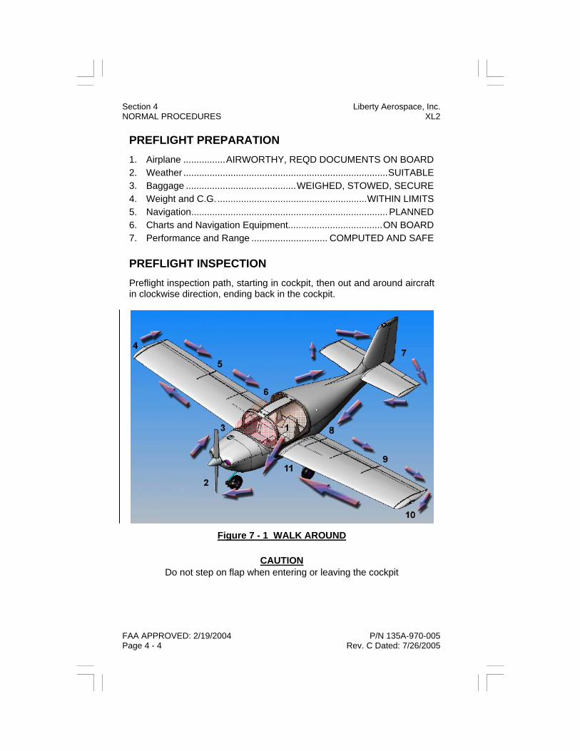
PREFLIGHT PREPARATION 1. Airplane ................AIRWORTHY, REQD DOCUMENTS ON BOARD 2. Weather ..............................................................................SUITABLE 3. Baggage ..........................................WEIGHED, STOWED, SECURE 4. Weight and C.G..........................................................WITHIN LIMITS 5. Navigation........................................................................... PLANNED 6. Charts and Navigation Equipment....................................ON BOARD 7. Performance and Range ............................. COMPUTED AND SAFE PREFLIGHT INSPECTION Preflight inspection path, starting in cockpit, then out and around aircraft in clockwise direction, ending back in the cockpit.
Figure 7 - 1 WALK AROUND
CAUTION Do not step on flap when entering or leaving the cockpit
FAA APPROVED: 2/19/2004 P/N 135A-970-005 Page 4 - 4 Rev. C Dated: 7/26/2005
Section 4 Liberty Aerospace, Inc. NORMAL PROCEDURES XL2
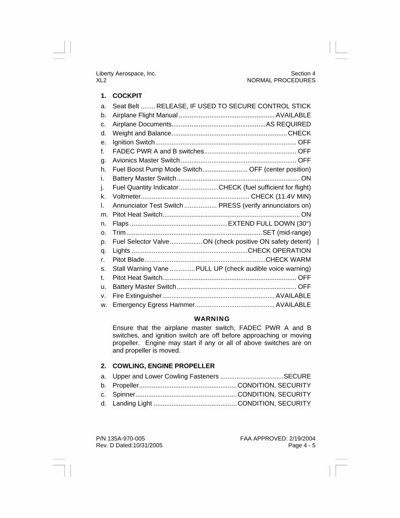
1. COCKPIT a. Seat Belt ........ RELEASE, IF USED TO SECURE CONTROL STICK b. Airplane Flight Manual ..................................................... AVAILABLE c. Airplane Documents....................................................AS REQUIRED d. Weight and Balance................................................................CHECK e. Ignition Switch.............................................................................. OFF f. FADEC PWR A and B switches................................................... OFF g. Avionics Master Switch................................................................ OFF h. Fuel Boost Pump Mode Switch......................... OFF (center position) i. Battery Master Switch.................................................................... ON j. Fuel Quantity Indicator......................CHECK (fuel sufficient for flight) k. Voltmeter............................................................ CHECK (11.4V MIN) l. Annunciator Test Switch .................. PRESS (verify annunciators on) m. Pitot Heat Switch............................................................................ ON n. Flaps ......................................................EXTEND FULL DOWN (30°) o. Trim...........................................................................SET (mid-range) p. Fuel Selector Valve..................ON (check positive ON safety detent) q. Lights ................................................................CHECK OPERATION r. Pitot Blade...................................................................CHECK WARM s. Stall Warning Vane ..............PULL UP (check audible voice warning) t. Pitot Heat Switch.......................................................................... OFF u. Battery Master Switch.................................................................. OFF v. Fire Extinguisher .............................................................. AVAILABLE w. Emergency Egress Hammer............................................ AVAILABLE
WARNING Ensure that the airplane master switch, FADEC PWR A and B switches, and ignition switch are off before approaching or moving propeller. Engine may start if any or all of above switches are on and propeller is moved.
2. COWLING, ENGINE PROPELLER a. Upper and Lower Cowling Fasteners ...................................SECURE b. Propeller......................................................CONDITION, SECURITY c. Spinner........................................................CONDITION, SECURITY d. Landing Light ..............................................CONDITION, SECURITY
P/N 135A-970-005 FAA APPROVED: 2/19/2004 Rev. D Dated:10/31/2005 Page 4 - 5
Liberty Aerospace, Inc. Section 4 XL2 NORMAL PROCEDURES
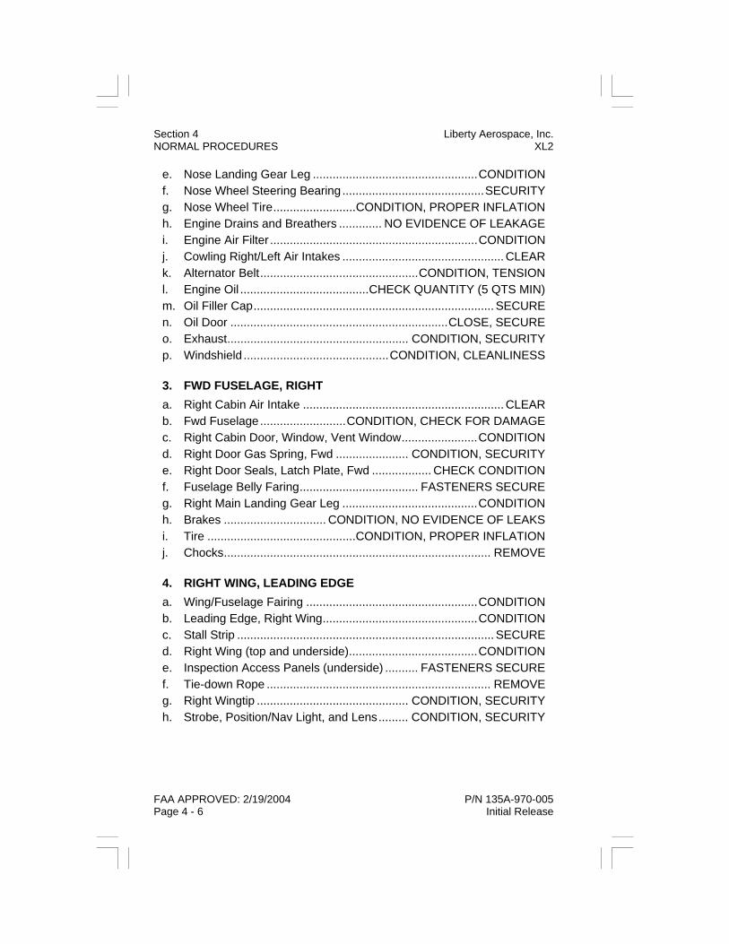
Section 4 Liberty Aerospace, Inc. NORMAL PROCEDURES XL2
FAA APPROVED: 2/19/2004 P/N 135A-970-005 Page 4 - 6 Initial Release
e. Nose Landing Gear Leg ..................................................CONDITION f. Nose Wheel Steering Bearing ...........................................SECURITY g. Nose Wheel Tire.........................CONDITION, PROPER INFLATION h. Engine Drains and Breathers ............. NO EVIDENCE OF LEAKAGE i. Engine Air Filter ...............................................................CONDITION j. Cowling Right/Left Air Intakes ................................................. CLEAR k. Alternator Belt................................................CONDITION, TENSION l. Engine Oil .......................................CHECK QUANTITY (5 QTS MIN) m. Oil Filler Cap......................................................................... SECURE n. Oil Door ..................................................................CLOSE, SECURE o. Exhaust....................................................... CONDITION, SECURITY p. Windshield ............................................CONDITION, CLEANLINESS 3. FWD FUSELAGE, RIGHT a. Right Cabin Air Intake ............................................................. CLEAR b. Fwd Fuselage..........................CONDITION, CHECK FOR DAMAGE c. Right Cabin Door, Window, Vent Window.......................CONDITION d. Right Door Gas Spring, Fwd ...................... CONDITION, SECURITY e. Right Door Seals, Latch Plate, Fwd .................. CHECK CONDITION f. Fuselage Belly Faring.................................... FASTENERS SECURE g. Right Main Landing Gear Leg .........................................CONDITION h. Brakes ............................... CONDITION, NO EVIDENCE OF LEAKS i. Tire .............................................CONDITION, PROPER INFLATION j. Chocks................................................................................. REMOVE 4. RIGHT WING, LEADING EDGE a. Wing/Fuselage Fairing ....................................................CONDITION b. Leading Edge, Right Wing...............................................CONDITION c. Stall Strip .............................................................................. SECURE d. Right Wing (top and underside).......................................CONDITION e. Inspection Access Panels (underside) .......... FASTENERS SECURE f. Tie-down Rope .................................................................... REMOVE g. Right Wingtip .............................................. CONDITION, SECURITY h. Strobe, Position/Nav Light, and Lens......... CONDITION, SECURITY

Liberty Aerospace, Inc. Section 4 XL2 NORMAL PROCEDURES
P/N 135A-970-005 FAA APPROVED: 2/19/2004 Initial Release Page 4 - 7
5. RIGHT WING, TRAILING EDGE a. Aileron................ CONDITION, FREE AND CORRECT MOVEMENT b. Aileron Hinges (2) .......................................CONDITION, SECURITY (hinge pins secured at both ends) c. Aileron Mass Balance Weights ............ UNOBSTRUCTED, SECURE d. Aileron Pushrod ...................................... CHECK JAMNUT SECURE e. Flap ................................................................................. CONDITION f. Flap Slot...................................................................................CLEAR g. Flap Hinges (3) .........CONDITION, SECURITY (cotter pins installed) 6. AFT FUSELAGE, RIGHT a. Fuselage Belly Faring ....................................FASTENERS SECURE b. Marker Beacon Antenna (underside)..........CONDITION, SECURITY c. Right Door Gas Spring, Aft .........................CONDITION, SECURITY d. Right Door Seals, Latch Plate, Aft .....................CHECK CONDITION e. Aft Fuselage............................ CONDITION, CHECK FOR DAMAGE f. Fuselage Mounted Antennas (top) .............CONDITION, SECURITY 7. EMPENNAGE a. Right Stabilator Pin, Nut, and Cotter Pins..........................SECURED b. Right Stabilator ......... CONDITION, SECURITY, FREE MOVEMENT c. Right Trim Tab .....CONDITION, SECURITY, FREE AND CORRECT MOVEMENT (hinge pins secured at both ends) d. Vertical Stabilizer ............................................................ CONDITION e. Rudder Gust Lock ................................................................REMOVE f. Rudder ...........................................CONDITION, FREE MOVEMENT g. Rudder Trim Tab (if installed) .....................CONDITION, SECURITY h. Rudder Hinge and Pin.................................CONDITION, SECURITY (hinge pin secured at both ends) i. Tie-down Rope.....................................................................REMOVE j. Left Trim Tab........CONDITION, SECURITY, FREE AND CORRECT MOVEMENT (hinge pins secured at both ends)

Section 4 Liberty Aerospace, Inc. NORMAL PROCEDURES XL2
FAA APPROVED: 2/19/2004 P/N 135A-970-005 Page 4 - 8 Initial Release
k. Left Stabilator ............CONDITION, SECURITY, FREE MOVEMENT l. Left Stabilator, Pin, Nut, and Cotter Pins .......................... SECURED
NOTE Stabilator trim tab should deflect in same direction as stabilator trail-ing edge (upward when trailing edge is deflected upward, downward when trailing edge is deflected downward) and should be faired with trailing edge when stabilator is in mid-range position.
8. AFT FUSELAGE, LEFT a. Aft Fuselage ............................CONDITION, CHECK FOR DAMAGE b. Fuel Filler Cap ..............................................CLOSED AND LOCKED c. Left Door Gas Spring, Aft ........................... CONDITION, SECURITY d. Left Door Seals, Latch Plate, Aft ....................... CHECK CONDITION e. Fuel Vent (underside)............................................UNOBSTRUCTED f. Transponder Antenna (underside) ............. CONDITION, SECURITY g. Outside Air Temp Probe (underside) ......................... ATTACHMENT h. Fuselage Belly Fairing................................... FASTENERS SECURE 9. LEFT WING, TRAILING EDGE a. Flap..................................................................................CONDITION b. Flap Slot .................................................................................. CLEAR c. Flap Hinges (3) ......... CONDITION, SECURITY (cotter pins installed) d. Aileron ................CONDITION, FREE AND CORRECT MOVEMENT e. Aileron Trim Tab (if installed) ..................... CONDITION, SECURITY f. Aileron Hinges (2)....................................... CONDITION, SECURITY (hinge pins secured at both ends) g. Aileron Mass Balance Weights.............UNOBSTRUCTED, SECURE h. Aileron Pushrod.......................................CHECK JAMNUT SECURE i. Left Wingtip................................................. CONDITION, SECURITY j. Strobe, Position/Nav Light, and Lens......... CONDITION, SECURITY

Liberty Aerospace, Inc. Section 4 XL2 NORMAL PROCEDURES
P/N 135A-970-005 FAA APPROVED: 2/19/2004 Initial Release Page 4 - 9
10. LEFT WING, LEADING EDGE a. Leading Edge, Left Wing ................................................ CONDITION b. Left Wing (top and underside) ........................................ CONDITION c. Pitot-Static Blade .......................... CONDITION, OPENINGS CLEAR d. Inspection Access Panels (underside)...........FASTENERS SECURE e. Tie-down Rope.....................................................................REMOVE f. Stall Warning Vane .....................................CONDITION, SECURITY g. Stall Strip...............................................................................SECURE h. Wing/Fuselage Fairing.................................................... CONDITION 11. FWD FUSELAGE, LEFT a. Left Main Landing Gear Leg ........................................... CONDITION b. Brakes................................CONDITION, NO EVIDENCE OF LEAKS c. Tire............................................. CONDITION, PROPER INFLATION d. Chocks .................................................................................REMOVE e. Fuselage Belly Fairing ...................................FASTENERS SECURE f. Fuel Tank Sump............. SAMPLE, CHECK FOR CONTAMINATION g. Fuel Strainer .................. SAMPLE, CHECK FOR CONTAMINATION h. Left Cabin Air Intake ................................................................CLEAR i. Left Cabin Door, Window, Vent Window......................... CONDITION j. Left Door Gas Spring, Fwd .........................CONDITION, SECURITY k. Left Door Seals, Latch Plate, Fwd .....................CHECK CONDITION

Section 4 Liberty Aerospace, Inc. NORMAL PROCEDURES XL2
FAA APPROVED: 2/19/2004 P/N 135A-970-005 Page 4 - 10 Initial Release
BEFORE STARTING ENGINE
CAUTION Avionics master switch must be off during engine start to prevent possible damage to the avionics.
1. Preflight Inspection.......................................................... COMPLETE 2. Passenger Briefing .......................................................... COMPLETE 3. Seat Cushions ................. Install and adjust to reference eye position
(see Section 7 - Airplane & Systems Description)
NOTE Ensure cushions do not obstruct control movement.
4. Seat Belts and Harnesses....................................ADJUST, SECURE 5. Rudder Pedals................................................ ADJUST AS DESIRED 6. Doors .......................................................................... AS REQUIRED 7. Fuel Boost Pump Mode Switch ....................................................OFF 8. Brakes .........................................TEST AND SET PARKING BRAKE 9. Fuel Selector Valve ..........................................................CHECK ON 10. Circuit Breakers..................................................................CHECK IN 11. Avionics Master Switch ................................................................OFF 12. Ignition Switch ..............................................................................OFF 13. All Other Electrical Switches ........................................................OFF
NOTE In calm wind conditions, doors may be left open for engine start and taxi at low power only. Close doors if there are gusty wind condi-tions or if high power is required for taxi.

STARTING ENGINE If the aircraft has been exposed to temperatures below -7°C / 20°F for more than 2 hours, preheating is required. If engine does not start on the first try, allow 2 minutes for the starter to cool before trying again.
WARNING If an abnormal HSA indication is observed during any operational check, takeoff is prohibited. Abort flight and notify maintenance. Do not attempt flight until the discrepancy has been corrected.
1. Brakes.......................................... CONFIRM PARKING BRAKE SET 2. Fuel Selector Valve.......................................................... VERIFY ON 3. Master (battery and alternator) Switch........................................... ON 4. FADEC PWR A and B Switches .................................................... ON
NOTE The FADEC PWR A and B switches are “lever lock” type. The switch handle must be pulled slightly away from the instrument panel to allow the switch to be moved.
5. Fuel Boost Pump Mode Switch...................................................... ON 6. Fuel Boost Pump .....................................LISTEN FOR OPERATION 7. Fuel Boost Pump Mode Switch..................................................AUTO 8. Fuel Boost Pump ...............LISTEN AND CONFIRM NOT RUNNING 9. HSA FUEL PMP Annunciator ....................... CHECK OFF (see note)
NOTE The FUEL PMP annunciator lamp may illuminate and the Fuel Boost Pump may operate after starting the engine, when the Fuel Boost Pump Mode Switch is in the AUTO position, until automatically de-activated by the FADEC System when the engine’s fuel pressure reaches acceptable levels.
10. Throttle.................................................................... FULL FORWARD 11. WOT Annunciator .............................................................CHECK ON 12. Throttle...............................................1/2 INCH FORWARD OF IDLE
P/N 135A-970-005 FAA APPROVED: 2/19/2004 Rev. C Dated: 7/26/2005 Page 4 - 11
Liberty Aerospace, Inc. Section 4 XL2 NORMAL PROCEDURES

13. WOT Annunciator ........................................................... CHECK OFF 14. Propeller Area.......................................................................... CLEAR
NOTE When the Fuel Boost Pump Switch is in the AUTO position, the Fuel Boost Pump will automatically be activated by the FADEC System when the ignition switch is placed in the L or BOTH position in the next step.
15. Ignition Switch ........................................................................ R (right) 16. Fuel Boost Pump......................................CONFIRM NOT RUNNING 17. Ignition Switch ...........................................................................L (left) 18. Fuel Boost Pump..................................... LISTEN FOR OPERATION 19. Ignition Switch ........................................................................... BOTH 20. Fuel Boost Pump..................................... LISTEN FOR OPERATION
NOTE A minimum of 5 seconds of fuel boost pump operation is required to ensure that fuel lines to the injectors are purged of air.
21. Ignition Switch ......................................................................... START (10 sec. maximum, release after engine starts) 22. Starter Engaged Annunciator Lamp.........................EXTINGUISHED 23. Throttle ...........................................RETARD, SET 1000 - 1200 RPM 24. Oil Pressure.........................CONFIRM RISING (within 30 sec. max.) 25. Engine Instruments ...........................................CHECK & MONITOR 26. Voltmeter ...............................................................CHECK (12V MIN) 27. HSA Test Button............PUSH, CHECK ALL LAMPS ILLUMINATED 28. HSA Test Button................................................................. RELEASE 29. HSA ...................... CHECK ALL LAMPS EXTINGUISHED (see note)
NOTE If airplane has not been operated for an extended period, HSA PPWR FL and/or EBAT FL annunciators may remain illuminated before, and for a few minutes after engine start.
FAA APPROVED: 2/19/2004 P/N 135A-970-005 Page 4 - 12 Rev. C Dated: 7/26/2005
Section 4 Liberty Aerospace, Inc. NORMAL PROCEDURES XL2

Liberty Aerospace, Inc. Section 4 XL2 NORMAL PROCEDURES
P/N 135A-970-005 FAA APPROVED: 2/19/2004 Initial Release Page 4 - 13
BEFORE TAXIING 1. HSA........................................CHECK ALL LAMPS EXTINGUISHED 2. Avionics Master Switch.................................................................. ON 3. Radios/Avionics ..........................................................AS REQUIRED 4. Lights ..........................................................................AS REQUIRED 5. Air Vents .....................................................................AS REQUIRED 6. Flaps ........................................................................................UP (0°) TAXIING When taxiing, maintain directional control using differential braking. Use the rudder only to assist during gusty wind conditions.
NOTE During all ground operations, a hand must be kept near the finger brake and throttle controls. Keep all taxi speeds to a minimum. Never exceed a brisk walking pace.
1. Parking Brake .....................................................................RELEASE 2. Brakes........................................................................................ TEST 3. Taxi .......................................................................................SLOWLY 4. Heading Indicator and Turn Coordinator ................................CHECK 5. Flight Controls.................USE CROSSWIND TAXIING TECHNIQUE

ENGINE RUNUP
WARNING If any rpm drop or engine surge occurs during the FADEC primary (PWR A) and secondary (PWR B) power transfer check, takeoff is prohibited. Abort flight and notify maintenance. Do not attempt flight until discrepancy has been corrected.
1. Stop into Wind .......................................................... CLEAR BEHIND 2. Parking Brake............... SET, CONFIRM AIRCRAFT NOT ROLLING 3. Canopy Doors (Both FWD pins and both AFT pins) ......... ENGAGED AND SECURE
NOTE Verify doors are closed by pushing on aft section of both door.
4. Oil Press/Temp...................................................... CHECK IN LIMITS 5. Throttle ...............................................................APPROX 1700 RPM 6. Fuel Boost Pump Mode Switch ....................................................OFF 7. HSA FUEL PMP Annunciator...........................................CHECK ON 8. Fuel Pressure ........................................................ CHECK IN LIMITS 9. Fuel Boost Pump Mode Switch ................................................. AUTO 10. HSA FUEL PMP Annunciator......................................... CHECK OFF 11. FADEC PWR A Switch.................................................................OFF 12. Engine .................................... CHECK, NO RPM DROP OR SURGE 13. HSA PPWR FL Annunciator (EBAT FL may come on) ....CHECK ON 14. FADEC PWR A Switch...................................................................ON 15. HSA ........................................CHECK ALL LAMPS EXTINGUISHED 16. FADEC PWR B Switch.................................................................OFF 17. Engine .................................... CHECK, NO RPM DROP OR SURGE 18. HSA EBAT FL Annunciator ..............................................CHECK ON 19. FADEC PWR B Switch...................................................................ON 20. HSA ........................................CHECK ALL LAMPS EXTINGUISHED 21. Ignition Switch .......................................................R (right) POSITON 22. RPM Drop............................................. 10 RPM MIN, 150 RPM MAX
FAA APPROVED: 2/19/2004 P/N 135A-970-005 Page 4 - 14 Rev. R Dated: 8/18/2009
Section 4 Liberty Aerospace, Inc. NORMAL PROCEDURES XL2

23. HSA................................. CHECK FADEC CAUTION ILLUMINATED 24. Ignition Switch............................................................................BOTH 25. HSA........................................CHECK ALL LAMPS EXTINGUISHED 26. Ignition Switch......................................................... L (left) POSITION 27. RPM Drop ............................................. 10 RPM MIN, 150 RPM MAX 28. HSA................................. CHECK FADEC CAUTION ILLUMINATED 29. Ignition Switch............................................................................BOTH 30. HSA........................................CHECK ALL LAMPS EXTINGUISHED
NOTE If the ignition switch is in the R or L position for more than 30 sec-onds, the red FADEC WARN annunciator will illuminate. This does not represent a fault condition, but is a reminder to the pilot to return the ignition switch to the BOTH position before flight.
31. Engine Instruments/Ammeter .........................RECHECK, MONITOR 32. Alternate Induction Air Knob ................................................ PULL ON 33. Alternate Induction Air Knob ............................................. PUSH OFF 34. Throttle.........................................................................................IDLE
P/N 135A-970-005 FAA APPROVED: 2/19/2004 Rev. R Dated: 8/18/2009 Page 4 - 15
Liberty Aerospace, Inc. Section 4 XL2 NORMAL PROCEDURES

BEFORE TAKEOFF
WARNING If any abnormal HSA indications are observed after all operational checks are complete, takeoff is prohibited. Abort flight and notify maintenance. Do not attempt flight until the discrepancy has been corrected.
During cold weather operations the engine should be properly warmed up before takeoff. The minimum oil temperature for takeoff is 75°F.
1. Flight Controls ................................................FREE AND CORRECT 2. Lights .......................................................................... AS REQUIRED 3. Ignition Switch .............................................................VERIFY BOTH 4. Flight and Engine Instruments....................................... SET, CHECK 5. Flaps...............................................................................................20° 6. Fuel Boost Pump Mode Switch ..................................VERIFY, AUTO
NOTE The normal configuration during all stages of flight for the Fuel Boost Pump Mode Switch is the AUTO position.
7. Trim ....................................... SET FOR TAKEOFF FLAP POSITION 8. Fuel Selector Valve .........................................................VERIFY, ON 9. Radios and Avionics..................................................................... SET 10. Transponder ..................................................................................ALT 11. Canopy Doors (Both FWD pins and both AFT pins) ......... ENGAGED AND SECURE
NOTE Verify doors are closed by pushing on aft section of both door.
12. Seat Belts & Harness............................................................ SECURE 13. Parking Brake Lever .....................................................................OFF 14. Brakes………...………………………………………………...RELEASE
FAA APPROVED: 2/19/2004 P/N 135A-970-005 Page 4 - 16 Rev. R Dated: 8/18/2009
Section 4 Liberty Aerospace, Inc. NORMAL PROCEDURES XL2

TAKEOFF Power check: check the full-throttle engine operation early in the takeoff run. The engine should turn approximately 2400 RPM and all engine instruments should read in the green. Abort takeoff at any sign of rough engine operation, sluggish acceleration, or abnormal annunciation.
Flap setting: the only approved flap setting for takeoff is 20°. Takeoff data is only presented for flaps 20°.
Soft or rough field takeoffs are performed by lifting the airplane off the ground as soon as practical. For takeoff on gravel or other rough sur-face apply throttle slowly to allow for debris to be blown behind the pro-peller rather than pulled up into it.
NORMAL TAKEOFF 1. Heading Indicator.................................VERIFY RUNWAY HEADING 2. Throttle.................................................................... FULL FORWARD 3. WOT Annunciator .............................................................CHECK ON 4. Engine Instruments .................................................................CHECK 5. Brakes...........................................RELEASE (steer with rudder only) 6. Elevator Control ............................. LIFT NOSE WHEEL (at 55 KIAS) 7. Takeoff Safety Speed ........................... ATTAIN (65 KIAS or greater) 8. Flaps ..............................................UP (at safe altitude and airspeed) 9. Climb Speed ....................................ACCELERATE TO 80 - 85 KIAS SOFT/ROUGH FIELD TAKEOFF 1. Heading Indicator.................................VERIFY RUNWAY HEADING 2. Throttle.................................................................... FULL FORWARD 3. WOT Annunciator .............................................................CHECK ON 4. Steer................................................................ WITH RUDDER ONLY 5. Elevator Control ...............................HOLD FULL BACK PRESSURE 6. When Airplane is Airborne .....................REDUCE PITCH ATTITUDE ACCELERATE TO 65 KIAS 7. Climb Speed .............................65 KIAS (until obstacles are cleared) 8. Flaps ..............................................UP (at safe altitude and airspeed) 9. Climb Speed ....................................ACCELERATE TO 80 - 85 KIAS
Liberty Aerospace, Inc. Section 4 XL2 NORMAL PROCEDURES
P/N 135A-970-005 FAA APPROVED: 2/19/2004 Rev. C Dated: 7/26/2005 Page 4 - 17

CLIMB Normal climbs are performed with full power and flaps up (0°) at speeds 5 - 10 knots faster than best rate-of-climb speed.
1. Throttle ....................................................................FULL FORWARD 2. WOT Annunciator .............................................................CHECK ON 3. Airspeed ..........................................................................80 - 85 KIAS
CRUISE CAUTION
Never cruise at full throttle (WOT annunciator illuminated). This will prevent engine fuel flow optimization and significantly reduce range.
1. Airspeed ....................................MAINTAIN POWER UNTIL CRUISE AIRSPEED IS ATTAINED 2. Power ..............................................................SET CRUISE POWER 3. Elevator Trim ............................................... ADJUST AS REQUIRED 4. Fuel Boost Pump Mode Switch ................................... CHECK AUTO 5. Engine Instruments and HSA.................................... CHECK OFTEN
NOTE For optimum fuel economy, do not change the throttle position for approximately five minutes after setting cruise power.
DESCENT 1. Power ......................................................................... AS REQUIRED 2. Elevator Trim ............................................... ADJUST AS REQUIRED 3. Engine Instruments and HSA.................................... CHECK OFTEN
Section 4 Liberty Aerospace, Inc. NORMAL PROCEDURES XL2
FAA APPROVED: 2/19/2004 P/N 135A-970-005 Page 4 - 18 Rev. C Dated: 7/26/2005

Liberty Aerospace, Inc. Section 4 XL2 NORMAL PROCEDURES
P/N 135A-970-005 FAA APPROVED: 2/19/2004 Initial Release Page 4 - 19
BEFORE LANDING 1. Fuel Quantity.....................................................CHECK SUFFICIENT 2. Fuel Boost Pump Mode Switch....................................CHECK AUTO 3. Brakes..............................................VERIFY PARKING BRAKE OFF 4. Fuel Selector Valve.......................................................... VERIFY ON 5. Flaps ............................................. AS DESIRED (at 80 KIAS or less) 6. Lights ..........................................................................AS REQUIRED 7. Seat Belts and Harnesses .................................................SECURED

Section 4 Liberty Aerospace, Inc. NORMAL PROCEDURES XL2
FAA APPROVED: 2/19/2004 P/N 135A-970-005 Page 4 - 20 Initial Release
LANDING Final approach airspeed is based on flap setting, stall speed at that flap setting, and other considerations such as traffic flow, airfield length, and possible wind gust factors.
The throttle should be smoothly reduced to idle upon entering the land-ing flare, and touchdown should be made at minimum speed on the main wheels. Maintaining back pressure to hold the nose up will provide considerable aerodynamic braking, and will reduce wear on the main gear and brakes. Lower the nose gently to the runway when it begins to settle on its own accord, then use minimum required braking. Be pre-pared to use differential braking for ground steering.
NORMAL LANDING 1. Airspeed ......................................................... 75 - 80 KIAS (flaps up) 2. Flaps..............................................AS DESIRED (at 80 KIAS or less) 3. Airspeed ........................................................ 70 - 75 KIAS (flaps 20°) 4. Airspeed ........................................................ 65 - 70 KIAS (flaps 30°) 5. Touchdown..................................................... MAIN WHEELS FIRST 6. Elevator Control........................................... LOWER NOSE GENTLY 7. Brakes .............................................................MINIMUM REQUIRED SHORT FIELD LANDING 1. Flaps...............................................................................................30° 2. Airspeed .........................................................65 KIAS UNTIL FLARE 3. Power ...........................................IDLE (after clearing any obstacles) 4. Touchdown..................................................... MAIN WHEELS FIRST 5. Elevator Control......................................LOWER NOSE PROMPTLY 6. Brakes ..................................................................... APPLY HEAVILY
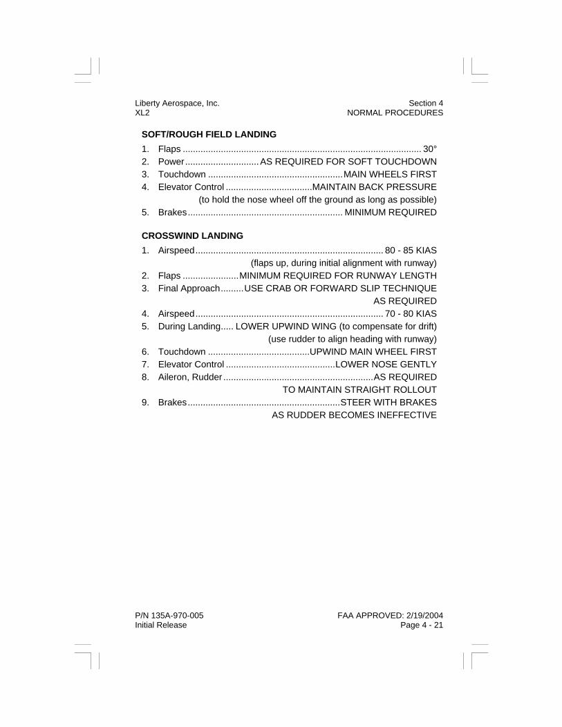
Liberty Aerospace, Inc. Section 4 XL2 NORMAL PROCEDURES
P/N 135A-970-005 FAA APPROVED: 2/19/2004 Initial Release Page 4 - 21
SOFT/ROUGH FIELD LANDING 1. Flaps .............................................................................................. 30° 2. Power.............................AS REQUIRED FOR SOFT TOUCHDOWN 3. Touchdown .....................................................MAIN WHEELS FIRST 4. Elevator Control ..................................MAINTAIN BACK PRESSURE (to hold the nose wheel off the ground as long as possible) 5. Brakes............................................................. MINIMUM REQUIRED CROSSWIND LANDING 1. Airspeed.......................................................................... 80 - 85 KIAS (flaps up, during initial alignment with runway) 2. Flaps ......................MINIMUM REQUIRED FOR RUNWAY LENGTH 3. Final Approach.........USE CRAB OR FORWARD SLIP TECHNIQUE AS REQUIRED 4. Airspeed.......................................................................... 70 - 80 KIAS 5. During Landing..... LOWER UPWIND WING (to compensate for drift) (use rudder to align heading with runway) 6. Touchdown ........................................UPWIND MAIN WHEEL FIRST 7. Elevator Control ...........................................LOWER NOSE GENTLY 8. Aileron, Rudder ...........................................................AS REQUIRED TO MAINTAIN STRAIGHT ROLLOUT 9. Brakes............................................................STEER WITH BRAKES AS RUDDER BECOMES INEFFECTIVE
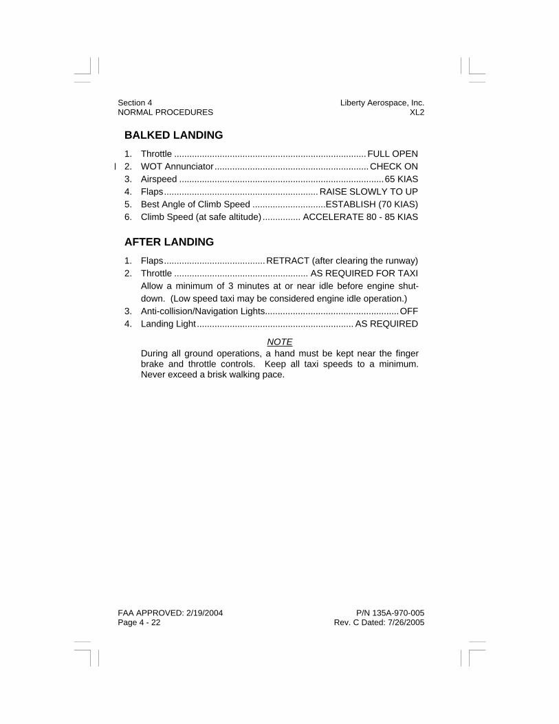
BALKED LANDING 1. Throttle ............................................................................ FULL OPEN 2. WOT Annunciator .............................................................CHECK ON 3. Airspeed .................................................................................65 KIAS 4. Flaps............................................................. RAISE SLOWLY TO UP 5. Best Angle of Climb Speed .............................ESTABLISH (70 KIAS) 6. Climb Speed (at safe altitude) ............... ACCELERATE 80 - 85 KIAS
AFTER LANDING 1. Flaps........................................RETRACT (after clearing the runway) 2. Throttle ..................................................... AS REQUIRED FOR TAXI
Allow a minimum of 3 minutes at or near idle before engine shut-down. (Low speed taxi may be considered engine idle operation.)
3. Anti-collision/Navigation Lights.....................................................OFF 4. Landing Light .............................................................. AS REQUIRED
NOTE During all ground operations, a hand must be kept near the finger brake and throttle controls. Keep all taxi speeds to a minimum. Never exceed a brisk walking pace.
FAA APPROVED: 2/19/2004 P/N 135A-970-005 Page 4 - 22 Rev. C Dated: 7/26/2005
Section 4 Liberty Aerospace, Inc. NORMAL PROCEDURES XL2

Liberty Aerospace, Inc. Section 4 XL2 NORMAL PROCEDURES
P/N 135A-970-005 FAA APPROVED: 2/19/2004 Initial Release Page 4 - 23
SHUTDOWN
WARNING If any abnormal HSA indications are observed after flight, or if the engine loses rpm when the fuel boost pump mode switch is turned off, advise maintenance immediately. Further flight is prohibited un-til the discrepancy has been corrected.
1. HSA........................................... CHECK ALL ANNUNCIATORS OFF 2. Fuel Boost Pump Mode Switch.................................................... OFF 3. Avionics Master Switch................................................................ OFF 4. Ignition Switch.............................................................................. OFF 5. FADEC PWR A and B Switches .................................................. OFF 6. All Electrical Switches.................................................................. OFF 7. All Light Switches......................................................................... OFF 8. Master Switch .............................................................................. OFF 9. ELT..................................................................................CHECK OFF
CAUTION If the secondary power (PWR B) switch is left in the ON position af-ter engine shutdown, the aircraft’s backup battery will discharge and be drained of power. Be sure to turn the primary (PWR A) and sec-ondary (PWR B) switches OFF after engine shutdown.

Section 4 Liberty Aerospace, Inc. NORMAL PROCEDURES XL2
FAA APPROVED: 2/19/2004 P/N 135A-970-005 Page 4 - 24 Initial Release
SECURING AIRPLANE 1. Wheels............................................................................... CHOCKED 2. Control Stick ............................................ SECURED BY SEAT BELT 3. Pitot Cover................................................................ ON (as required) 4. Rudder Gust Lock .................................................... ON (as required) 5. Wings and Tail...................................................................TIE-DOWN 6. Doors ..........................................................CLOSED AND LATCHED

SECTION 5
PERFORMANCE
TABLE OF CONTENTS
Introduction ............................................................................ 5 - 3 Airspeed Calibration............................................................... 5 - 4 Normal Static Source ...................................................... 5 - 4 Alternate Static Source.................................................... 5 - 5 Crosswind Component Graph ............................................... 5 - 6 Stall Speeds........................................................................... 5 - 7 Temperature Chart................................................................. 5 - 8 Takeoff Distance.................................................................... 5 - 9 Maximum Rate of Climb ...................................................... 5 - 11 Maximum Climb Gradient .................................................... 5 - 12 Balked Landing Rate of Climb ............................................. 5 - 13 Balked Landing Climb Gradient ........................................... 5 - 14 Landing Distance ................................................................. 5 - 15 Best Glide Speed and Distance........................................... 5 - 17 Noise Characteristics / Abatement ...................................... 5 - 18
P/N 135A-970-005 FAA APPROVED: 2/19/2004 Rev. C Dated: 7/26/2005 Page 5 - 1
Liberty Aerospace, Inc. Section 5 XL2 PERFORMANCE

Section 5 Liberty Aerospace, Inc. PERFORMANCE XL2
FAA APPROVED: 2/19/2004 P/N 135A-970-005 Page 5 - 2 Initial Release
THIS PAGE INTENTIONALLY LEFT BLANK

INTRODUCTION This section contains information describing the performance of the Lib-erty XL2 airplane throughout its flight envelope.
Performance information presented in this section is based on data ob-tained by flight tests. No unusual pilot techniques were used, or are re-quired to obtain published performance. Flight test data were obtained using a new aircraft and engine equipped with a representative selection of optional equipment, including avionics and antennas.
All data is applicable to aircraft with and without wheel fairings installed.
CAUTION Achievement of published performance requires pilot compliance with all conditions called out in individual performance charts and/or tables.
P/N 135A-970-005 FAA APPROVED: 2/19/2004 Rev. N Dated: 12/14/2007 Page 5 - 3
Liberty Aerospace, Inc. Section 5 XL2 PERFORMANCE

AIRSPEED CALIBRATION Normal Static Source
Conditions: Power .......................................................................for level flight Weight ...........................................................................1653 LBS
Note: • Indicated airspeed values do not include instrument error.
KIAS KCAS Flaps
0° 20° 30° 40 - - 44
50 54 54 54
60 64 63 63
70 73 72 72
80 83 81 81
90 92 - -
100 101 - -
110 110 - -
120 120 - -
130 129 - -
140 138 - -
150 146 - -
160 155 - -
FAA APPROVED: 2/19/2004 P/N 135A-970-005 Page 5 - 4 Rev. C Dated: 7/26/2005
Section 5 Liberty Aerospace, Inc. PERFORMANCE XL2

AIRSPEED CALIBRATION Alternate Static Source
Conditions: Power....................................................................... for level flight Weight........................................................................... 1653 LBS Vents................................................................................... OPEN
Note: • Indicated airspeed values do not include instrument error.
KIAS KCAS Flaps
0° 20° 30° 40 - - 39
50 49 49 49
60 58 60 60
70 68 70 70
80 77 79 79
90 86 - -
100 95 - -
110 104 - -
120 113 - -
130 122 - -
140 130 - -
150 138 - -
160 147 - -
P/N 135A-970-005 FAA APPROVED: 2/19/2004 Rev. C Dated: 7/26/2005 Page 5 - 5
Liberty Aerospace, Inc. Section 5 XL2 PERFORMANCE

Section 5 Liberty Aerospace, Inc. PERFORMANCE XL2
FAA APPROVED: 2/19/2004 P/N 135A-970-005 Page 5 - 6 Initial Release
CROSSWIND COMPONENT GRAPH Directions: Enter graph at wind velocity on left, read across to diagonal line showing angular difference between runway heading and wind di-rection, read down to crosswind component at bottom.
Notes: • The maximum demonstrated crosswind is 15 knots. • The demonstrated crosswind component is based on the
greatest crosswind available during flight testing and is not considered a limitation.

STALL SPEEDS Conditions:
Weight........................................................................... 1653 LBS C.G........................................ Most Forward for Maximum Weight Power.......................................................................................Idle Bank Angle...........................................................................Noted
Weight LBS
Bank Angle (Deg)
STALL SPEEDS
Flaps 0° Flaps Flaps 30° Full Up 20° Full Down
KIAS KCAS KIAS KCAS KIAS KCAS
1653
0 51 55 43 47 41 45 15 52 56 44 48 42 46 30 55 59 47 51 44 48 45 61 65 53 56 50 54 60 75 78 64 66 62 64
P/N 135A-970-005 FAA APPROVED: 2/19/2004 Rev. G Dated: 5/19/2006 Page 5 - 7
Liberty Aerospace, Inc. Section 5 XL2 PERFORMANCE

Section 5 Liberty Aerospace, Inc. PERFORMANCE XL2
FAA APPROVED: 2/19/2004 P/N 135A-970-005 Page 5 - 8 Initial Release
TEMPERATURE CHART This graph provides information on standard temperatures to be ex-pected at various cruise altitudes. In addition, the temperature axis of the chart may be used to convert between Fahrenheit and Celsius tem-perature values.
Enter the graph at the desired altitude on the left and read across until reaching the desired diagonal temperature line. Read down to obtain temperature at the specified altitude in degrees C or F.
FT
SL -5 23 5 41 15 59 25 77 45 113
1000 -7 19 3 37 13 55 23 73 43 109
2000 -9 16 1 34 11 52 21 70 41 106
3000 -11 12 -1 30 9 48 19 66 39 102
4000 -13 9 -3 27 7 45 17 63 37 99
5000 -15 5 -5 23 5 41 15 59 35 95
6000 -17 1 -7 19 3 37 13 55 33 91
7000 -19 -2 -9 16 1 34 11 52 31 88
8000 -21 -6 -11 12 -1 30 9 48 29 84
9000 -23 -9 -13 9 -3 27 7 45 27 81
10000 -25 -13 -15 5 -5 23 5 41 25 77
11000 -27 -17 -17 1 -7 19 3 37 23 73
12000 -29 -20 -19 -2 -9 16 1 34 21 70
13000 -31 -24 -21 -6 -11 12 -1 30 19 66
14000 -33 -27 -23 -9 -13 9 -3 27 17 63
ISA + 30°C
°C °F°F
ISA + 10°C
°C °F
ISA - 20°C ISA - 10°C ISA
°C °F °C °C °F
Press Alt

Liberty Aerospace, Inc. Section 5 XL2 PERFORMANCE
P/N 135A-970-005 FAA APPROVED: 2/19/2004 Initial Release Page 5 - 9
TAKEOFF DISTANCE Begin the flight planning process by confirming that runway length is adequate for takeoff based on gross weight, altitude, and temperature. Use correction factors provided in the following notes to compensate for headwind or tailwind components and temperature deviations. Normal takeoff assumes acceleration to best rate of climb airspeed.
Conditions: Winds .....................................................................................Zero Runway .............................................................Dry, Level, Paved Weight........................................................................... 1653 LBS Flaps ........................................................................................20° Rotation Speed ................................................................ 55 KIAS Speed at 50 ft above takeoff surface ............................... 65 KIAS Power................................... Full Throttle (WOT annunciator ON) Prior to brake release
Notes: • Increase distances 15% when CHT’s are 420°F or greater. • To be conservative, use the distance for the next higher
Pressure Altitude or Temperature than actual. For example, at a pressure altitude of 475 ft and temperature of 4°C use the takeoff distance for a pressure altitude of 1000 ft and temperature of 10°C.
• Decrease distances 10% for each 12 knots headwind com-ponent. For operation with tailwind component, up to 10 knots, increase distances 10% for each 2 knots.
• For operation on dry grass runways, increase “gnd roll” dis-tances by 15%.
• For operation in air colder than this table provides, use cold-est data shown.
• For operation in air warmer than this table provides, use extreme caution.
• Data was derived from actual flight testing and does not in-clude data for any altitude where the temperature is below ISA -20° or above ISA +30°.

Section 5 Liberty Aerospace, Inc. PERFORMANCE XL2
FAA APPROVED: 2/19/2004 P/N 135A-970-005 Page 5 - 10 Initial Release
TAKEOFF DISTANCE Rotation Speed: 55 KIAS Flaps 20° Speed at 50 ft: 65 KIAS
Distance Temperature - °C
FT FT 0 10 20 30 40 ISA
SL Gnd Roll 704 781 864 953 1047 822 Over 50FT 1284 1423 1571 1729 1897 1496
1000 Gnd Roll 770 855 945 1042 1145 881 Over 50FT 1399 1551 1713 1885 2068 1598
2000 Gnd Roll 838 930 1029 1134 1246 940 Over 50FT 1519 1684 1859 2046 2245 1701
3000 Gnd Roll 918 1019 1127 1243 1009 Over 50FT 1659 1838 2030 2234 1820
4000 Gnd Roll 1002 1112 1229 1355 1078 Over 50FT 1803 1998 2207 2428 1939
5000 Gnd Roll 1098 1219 1348 1486 1158 Over 50FT 1971 2184 2412 2654 2076
6000 Gnd Roll 1199 1331 1472 1622 1238 Over 50FT 2144 2376 2624 2888 2212
7000 Gnd Roll 1345 1493 1651 1820 1360 Over 50FT 2397 2657 2934 3228 2422
8000 Gnd Roll 1497 1662 1838 1481 Over 50FT 2659 2947 3255 2632
9000 Gnd Roll 1680 1865 2063 1627 Over 50FT 2974 3296 3640 2882
10000 Gnd Roll 1871 2077 2296 1773 Over 50FT 3301 3659 4040 3132
Press Alt
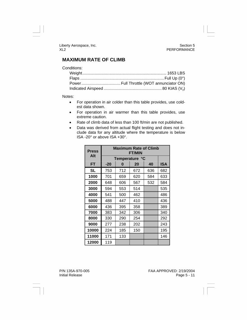
Liberty Aerospace, Inc. Section 5 XL2 PERFORMANCE
P/N 135A-970-005 FAA APPROVED: 2/19/2004 Initial Release Page 5 - 11
MAXIMUM RATE OF CLIMB Conditions:
Weight........................................................................... 1653 LBS Flaps ........................................................................... Full Up (0°) Power................................... Full Throttle (WOT annunciator ON) Indicated Airspeed .................................................... 80 KIAS (Vy)
Notes: • For operation in air colder than this table provides, use cold-
est data shown. • For operation in air warmer than this table provides, use
extreme caution. • Rate of climb data of less than 100 ft/min are not published. • Data was derived from actual flight testing and does not in-
clude data for any altitude where the temperature is below ISA -20° or above ISA +30°.
Press Alt
Maximum Rate of Climb FT/MIN
Temperature °C FT -20 0 20 40 ISA SL 753 712 672 636 682
1000 701 659 620 584 633 2000 648 606 567 532 584 3000 594 553 514 535 4000 541 500 462 486 5000 488 447 410 436 6000 436 395 358 389 7000 383 342 306 340 8000 330 290 254 292 9000 277 238 202 243 10000 224 185 150 195 11000 171 133 146 12000 119

Section 5 Liberty Aerospace, Inc. PERFORMANCE XL2
FAA APPROVED: 2/19/2004 P/N 135A-970-005 Page 5 - 12 Initial Release
MAXIMUM CLIMB GRADIENT Conditions:
Weight ...........................................................................1653 LBS Flaps............................................................................Full Up (0°) Power .................................. Full Throttle (WOT annunciator ON) Indicated Airspeed.....................................................80 KIAS (Vy)
Notes: • For operation in air colder than this table provides, use cold-
est data shown. • For operation in air warmer than this table provides, use
extreme caution. • Climb gradient data of less than 100 ft/nm are not published. • Data was derived from actual flight testing and does not in-
clude data for any altitude where the temperature is below ISA -20° or above ISA +30°.
Press Alt
Maximum Climb Gradient FT/NM
Temperature °C FT -20 0 20 40 ISA SL 603 549 500 457 512
1000 551 499 453 412 468 2000 500 450 406 368 425 3000 450 403 362 384 4000 401 357 319 343 5000 356 314 278 304 6000 311 272 237 266 7000 269 232 200 230 8000 227 192 162 194 9000 187 155 127 160 10000 148 118 125 11000 112

Liberty Aerospace, Inc. Section 5 XL2 PERFORMANCE
P/N 135A-970-005 FAA APPROVED: 2/19/2004 Initial Release Page 5 - 13
BALKED LANDING RATE OF CLIMB Conditions:
Weight........................................................................... 1653 LBS Flaps ........................................................................................30° Power................................... Full Throttle (WOT annunciator ON) Indicated Airspeed ........................................................... 65 KIAS
Notes: • For operation in air colder than this table provides, use cold-
est data shown. • For operation in air warmer than this table provides, use
extreme caution. • Rate of climb data of less than 100 ft/min are not published. • Data was derived from actual flight testing and does not in-
clude data for any altitude where the temperature is below ISA -20° or above ISA +30°.
Press Alt
Balked Landing Rate of Climb FT/MIN
Temperature °C FT -20 0 20 40 ISA SL 456 417 382 349 391
1000 408 370 334 302 346 2000 360 322 287 255 302 3000 311 274 239 258 4000 263 226 192 214 5000 214 177 144 169 6000 168 131 126 7000 120
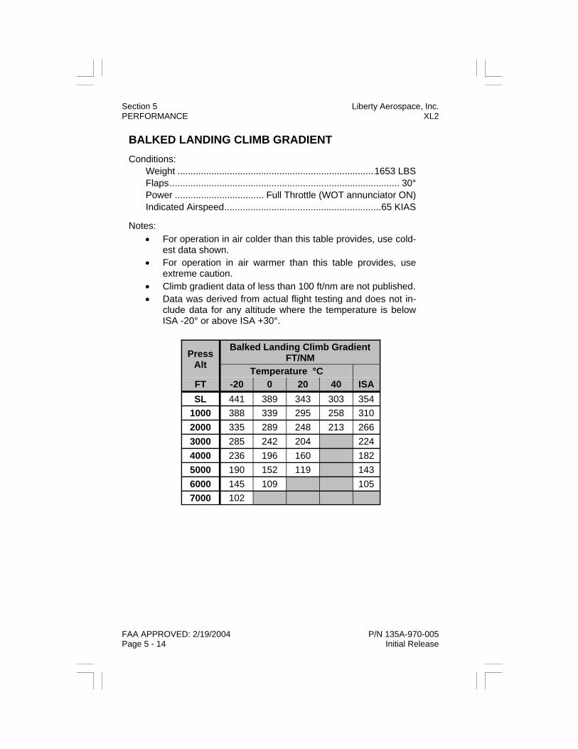
Section 5 Liberty Aerospace, Inc. PERFORMANCE XL2
FAA APPROVED: 2/19/2004 P/N 135A-970-005 Page 5 - 14 Initial Release
BALKED LANDING CLIMB GRADIENT Conditions:
Weight ...........................................................................1653 LBS Flaps........................................................................................ 30° Power .................................. Full Throttle (WOT annunciator ON) Indicated Airspeed............................................................65 KIAS
Notes: • For operation in air colder than this table provides, use cold-
est data shown. • For operation in air warmer than this table provides, use
extreme caution. • Climb gradient data of less than 100 ft/nm are not published. • Data was derived from actual flight testing and does not in-
clude data for any altitude where the temperature is below ISA -20° or above ISA +30°.
Press Alt
Balked Landing Climb Gradient FT/NM
Temperature °C FT -20 0 20 40 ISA SL 441 389 343 303 354
1000 388 339 295 258 310 2000 335 289 248 213 266 3000 285 242 204 224 4000 236 196 160 182 5000 190 152 119 143 6000 145 109 105 7000 102

Liberty Aerospace, Inc. Section 5 XL2 PERFORMANCE
P/N 135A-970-005 FAA APPROVED: 2/19/2004 Initial Release Page 5 - 15
LANDING DISTANCE Landing performance charts are based on the airplane crossing the run-way threshold at 50 ft AGL and at the indicated airspeed specified in the chart.
Conditions: Winds .....................................................................................Zero Runway .............................................................Dry, Level, Paved Weight........................................................................... 1653 LBS Flaps .................................................................... Full Down (30°) Power.................................................................................... IDLE Braking........................................................................... Moderate Speed at 50 ft above landing surface .............................. 65 KIAS
Notes: • To be conservative, use the distance for the next higher
Pressure Altitude or Temperature than actual. For example, at a pressure altitude of 475 ft and temperature of 4°C use the takeoff distance for a pressure altitude of 1000 ft and temperature of 10°C.
• Decrease distances 10% for each 12 knots headwind com-ponent. For operation with tailwind component, up to 10 knots, increase distances 10% for each 2 knots.
• For operation on dry grass runways, increase “gnd roll” dis-tances by 15%.
• For operation in air colder than this table provides, use cold-est data shown.
• For operation in air warmer than this table provides, use extreme caution.
• Data was derived from actual flight testing and does not in-clude data for any altitude where the temperature is below ISA -20° or above ISA +30°.

Section 5 Liberty Aerospace, Inc. PERFORMANCE XL2
FAA APPROVED: 2/19/2004 P/N 135A-970-005 Page 5 - 16 Initial Release
LANDING DISTANCE Speed at 50 ft: 65 KIAS Flaps 30°
Press Alt Distance
FT FT 0 10 20 30 40 ISA
SL Gnd Roll 797 826 856 885 914 841 Over 50FT 1457 1498 1539 1580 1620 1519
1000 Gnd Roll 827 857 887 918 948 867 Over 50FT 1499 1541 1584 1626 1668 1555
2000 Gnd Roll 857 888 920 951 983 892 Over 50FT 1542 1585 1629 1672 1716 1590
3000 Gnd Roll 890 922 955 988 920 Over 50FT 1587 1632 1677 1722 1628
4000 Gnd Roll 923 957 991 1024 947 Over 50FT 1633 1680 1726 1773 1666
5000 Gnd Roll 959 994 1029 1064 977 Over 50FT 1682 1730 1778 1827 1707
6000 Gnd Roll 995 1031 1068 1104 1006 Over 50FT 1732 1781 1831 1881 1747
7000 Gnd Roll 1055 1094 1133 1171 1059 Over 50FT 1822 1875 1927 1979 1827
8000 Gnd Roll 1116 1157 1199 1113 Over 50FT 1913 1968 2023 1907
9000 Gnd Roll 1184 1227 1271 1171 Over 50FT 2012 2070 2128 1994
10000 Gnd Roll 1253 1298 1344 1229 Over 50FT 2112 2174 2235 2081
Temperature - °C

BEST GLIDE SPEED AND DISTANCE
GLIDE DISTANCE CHART
Conditions: Flaps ........................................................................... Full Up (0°) Power..........................................................IDLE, Throttle Closed Prop.............................................................................Windmilling Airspeed........................................................................... 80 KIAS Flight Attitude .................................... Straight Glide (NO TURNS)
WARNING No allowance included for landing pattern, any turns and/or devia-tions from correct glide speed will reduce glide distance.
Aircraft Gross Weight Best Glide Speed
1653 LBS 80 KIAS
0
1000
2000
3000
4000
5000
6000
7000
8000
9000
10000
0 2 4 6 8 10 12 14 16 18 20
Miles
Alti
tude
Los
s
P/N 135A-970-005 FAA APPROVED: 2/19/2004 Rev. H Dated: 7/5/2006 Page 5 - 17
Liberty Aerospace, Inc. Section 5 XL2 PERFORMANCE

Section 5 Liberty Aerospace, Inc. PERFORMANCE XL2
FAA APPROVED: 2/19/2004 P/N 135A-970-005 Page 5 - 18 Initial Release
NOISE CHARACTERISTICS The certificated noise level for the Liberty XL2 established in accordance with FAR 36 Appendix G, through Amendment 24 is:
74.6 dB(A)
No determination has been made by the Federal Aviation Administration that the noise levels of this airplane are or should be acceptable or un-acceptable for operation at, into, or out of, any airport.

Liberty Aerospace, Inc. Section 6 XL2 WEIGHT AND BALANCE
P/N 135A-970-005 FAA APPROVED: 2/19/2004 Initial Release Page 6 - 1
SECTION 6
WEIGHT & BALANCE
TABLE OF CONTENTS
Introduction ............................................................................ 6 - 3 Airplane Weighing Procedures .............................................. 6 - 4 Determining Airplane Weight & Balance................................ 6 - 7 Calculation of C.G. in Terms of Station ................................. 6 - 9 Airplane Weighing Record ................................................... 6 - 10 Empty Center of Gravity Calculation.................................... 6 - 10 Center of Gravity Limits ....................................................... 6 - 11 Airplane Loading Diagram ................................................... 6 - 12 Loading Graph ..................................................................... 6 - 13 Loading Chart ...................................................................... 6 - 14 Airplane Loading Worksheet................................................ 6 - 15 Loaded Airplane Total Moment Limitations ......................... 6 - 16 Loaded Airplane C.G. (ARM) Limitations............................. 6 - 17 Record of Weight and Balance Changes............................. 6 - 18

Section 6 Liberty Aerospace, Inc. WEIGHT AND BALANCE XL2
FAA APPROVED: 2/19/2004 P/N 135A-970-005 Page 6 - 2 Initial Release
THIS PAGE INTENTIONALLY LEFT BLANK

Liberty Aerospace, Inc. Section 6 XL2 WEIGHT AND BALANCE
P/N 135A-970-005 FAA APPROVED: 2/19/2004 Initial Release Page 6 - 3
INTRODUCTION This section describes the procedure for establishing the basic empty weight and moment of the airplane. When this moment is divided by the airplane weight, the result is the moment arm of center of gravity location (C.G.). Sample forms are provided for reference, and may be photocop-ied as required. Procedures for calculating weight and moment, and ensuring compliance with aircraft limitations, are also included. A com-prehensive list of standard and optional equipment available for this air-plane is provided at the back of this section.
It should be noted that specific information regarding the weight, arm, moment, and installed equipment for this airplane, as delivered from the factory, can only be found in the original weight and balance report in-corporated in this section.
WARNING It is the responsibility of the pilot-in-command to ensure that the air-plane is loaded properly. Operation outside of prescribed weight and balance limitations could result in an accident and serious or fatal injury.
Section 6 Liberty Aerospace, Inc. WEIGHT AND BALANCE XL2
FAA APPROVED: 2/19/2004 P/N 135A-970-005 Page 6 - 4 Initial Release
AIRPLANE WEIGHING PROCEDURES LEVELING
The airplane must be level both laterally and longitudinally before it is weighed.
To determine lateral level, place a beam level across both cabin doorsills (and at exact right angles to the airplane centerline) with the doors open. Measurement from the forward or aft end of the doorsill may be used to determine that the level has been placed correctly.
To determine longitudinal level, place a beam level lengthwise along either cabin doorsill with the cabin door open. WEIGHING
Required Equipment:
• Three mechanical or electrical scales, minimum capacity 800 lbs each main gear, and 500 lbs nose gear.
• Ramps to roll airplane onto scales; chocks to secure airplane wheels on scales; shim material to level airplane.
Procedure:
NOTE Weighing must be carried out indoors and in a location free from air currents.
a. Verify that all required equipment is installed and complete. Ensure that any other items are removed from baggage area and cockpit storage pockets, etc.
b. Drain all fuel from airplane. Then add published amount of unusable fuel to the fuel tank (1.5 U.S. gallons).
c. Service engine oil to maximum mark on dipstick.
d. Ensure flaps are retracted and all flight controls are in neutral posi-tion.

e. Roll airplane onto scales. Ensure that nose wheel is centered and that main wheel legs do not exert any side loads on scales. Close both canopy doors. Chock all wheels securely. NOTE: tare weight of chocks must be subtracted from airplane wheel weights.
f. Use shim materials as necessary to level airplane laterally and longi-tudinally.
NOTE Shim materials may be used either on or under scales for leveling. If used on scales, tare weight of shim materials must be subtracted from airplane wheel weights. Make the last “fine adjustments” to achieve perfect level by letting small amounts of air out of the air-plane tires.
For calculating the aircraft weight and center of gravity, the distance be-tween the XL2’s nose wheel and main wheels is 57.51 inches (measurement ‘y’), with the midpoint being 28.75 inches (Figure 6-1). The distance between the centerline of the two main gears is 70.36 inches, or 35.18 inches from centerline of each main wheel to centerline of airplane (Figure 1-1).
Liberty Aerospace, Inc. Section 6 XL2 WEIGHT AND BALANCE
P/N 135A-970-005 FAA APPROVED: 2/19/2004 Rev. G Dated: 5/19/2006 Page 6 - 5

Figure 6-1 Airplane Dimensional Data
Section 6 Liberty Aerospace, Inc. WEIGHT AND BALANCE XL2
FAA APPROVED: 2/19/2004 P/N 135A-970-005 Page 6 - 6 Rev. G Dated: 5/19/2006

DETERMINING AIRPLANE WEIGHT & BALANCE This XL2 airplane was weighed just prior to initial delivery and a basic empty weight and center of gravity was established. The distance from nose wheel to main wheels is 57.51 inches. This dimension is used to calculate the aircraft weight and center of gravity.
However, major modifications, loss of records, addition or relocation of equipment, completion of service bulletins, and weight-gain over time, may require re-weighing of the aircraft to keep the basic empty weight and center of gravity current. All changes to the basic empty weight and center of gravity are the responsibility of the pilot-in-command.
1. Preparation:
a. Inflate tires to recommended operating pressures. b. Service brake reservoir. c. Remove the fuel tank sump drain fittings and fuel gascolator
valve drain plug to drain all fuel. d. Service engine oil. e. Raise flaps up. f. Place all control surfaces in neutral position. g. Verify equipment installation and location by comparison to
equipment list. h. Tare the scales.
2. Leveling:
a. Place scales under each wheel (scale capacity, 500 lbs nose, 1000 lbs each main).
b. Level longitudinally with a spirit level placed on the pilot doorsill and laterally with a spirit level placed across the doorsills. Alter-nately, level airplane by sighting the forward and aft tool holes along waterline 50.0. Shim underneath scales as required to attain proper level.
3. Weighing:
a. With the airplane level, doors closed, and brakes released, re-cord the weight shown on each scale.
Liberty Aerospace, Inc. Section 6 XL2 WEIGHT AND BALANCE
P/N 135A-970-005 FAA APPROVED: 2/19/2004 Rev. G Dated: 5/19/2006 Page 6 - 7

4. Multiply the weight for each main wheel by its distance aft of the ref-erence datum. This is the wheel moment. Multiply the weight for the nose wheel by its distance aft of the reference datum. This is the nose wheel moment.
Moment (in.lbs.) = Net Weight (lbs.) x Arm (in.)
5. Calculate and record the as-weighed moment by totaling the appro-priate columns.
6. Determine and record the as-weighed C.G. in inches aft of datum using the following formula:
C.G. (in.) = Total Moment (in.lbs.) ÷ Total Weight (lbs.)
5. Add or subtract any items not included in the as-weighed condition to determine the empty condition. Application of the above C.G. formula will determine the C.G. for this condition.
6. Add the correction for engine oil (15 lbs at STN 38.09), if the air-plane was weighed with oil drained. Add the correction for unusable fuel (9.0 lbs at STN 101.80) to determine the Basic Empty Weight C.G. by applying the above C.G. formula.
7. Record the new weight and C.G. values on the Weight and Balance Record (Figure 6-1).
The above procedure determines the airplane Basic Empty Weight, mo-ment, and center of gravity in inches aft of datum. Add all three mo-ments together (left and right main wheel or jack point plus nose wheel). This is the (empty airplane) total moment. Divide the total moment by the total empty weight (sum of left, right, and nose wheel weights). The result, expressed in inches aft of the reference datum, is the location of the empty airplane’s center of gravity.
NOTE To reduce the number of digits in calculations, it is acceptable to divide moments by 1000, and express them as “moment/1000.” Care must be exercised to maintain consistency throughout all cal-culations.
Section 6 Liberty Aerospace, Inc. WEIGHT AND BALANCE XL2
FAA APPROVED: 2/19/2004 P/N 135A-970-005 Page 6 - 8 Rev. M Dated: 05/22/07

CALCULATION OF C.G. IN TERMS OF STATION Location of the forward edge of canopy hoop (the forward edge of the open canopy door) as Station 70.75, which is 70.75 inches aft of the ref-erence datum (Figure 6-2).
Figure 6-2 Airplane Dimensional Data
A = 95.60”, B = 38.09”, Y = 57.51”
Liberty Aerospace, Inc. Section 6 XL2 WEIGHT AND BALANCE
P/N 135A-970-005 FAA APPROVED: 2/19/2004 Rev. G Dated: 5/19/2006 Page 6 - 9
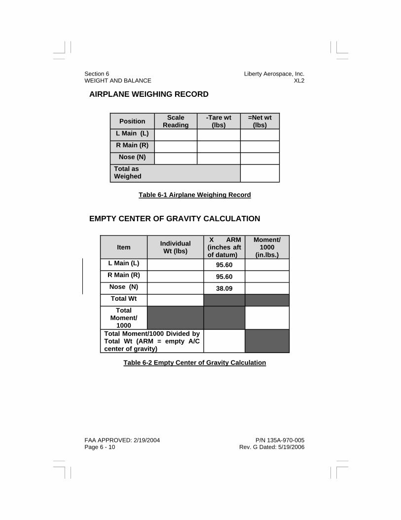
AIRPLANE WEIGHING RECORD
Table 6-1 Airplane Weighing Record
EMPTY CENTER OF GRAVITY CALCULATION
Table 6-2 Empty Center of Gravity Calculation
Position Scale Reading
-Tare wt (lbs)
=Net wt (lbs)
L Main (L)
R Main (R)
Nose (N)
Total as Weighed
Item Individual Wt (lbs)
X ARM (inches aft of datum)
Moment/ 1000
(in.lbs.) L Main (L) 95.60
R Main (R) 95.60
Nose (N) 38.09
Total Wt
Total Moment/
1000
Total Moment/1000 Divided by Total Wt (ARM = empty A/C center of gravity)
Section 6 Liberty Aerospace, Inc. WEIGHT AND BALANCE XL2
FAA APPROVED: 2/19/2004 P/N 135A-970-005 Page 6 - 10 Rev. G Dated: 5/19/2006

CENTER OF GRAVITY LIMITS
Table 6-3 Center of Gravity Limits
Gal. Weight (lbs)
Arm (in)
Moment (in.lbs.)
Empty Wt 1174 83.20 97676.8 Pilot 79.78 Copilot 79.78 Fuel 0.0 101.80 Baggage 118.00 Zero Fuel 1174 83.20 97676.8 Ramp Weight 1174 83.20 97676.8
Liberty Aerospace, Inc. Section 6 XL2 WEIGHT AND BALANCE
P/N 135A-970-005 FAA APPROVED: 2/19/2004 Rev. M Dated: 05/22/07 Page 6 - 11
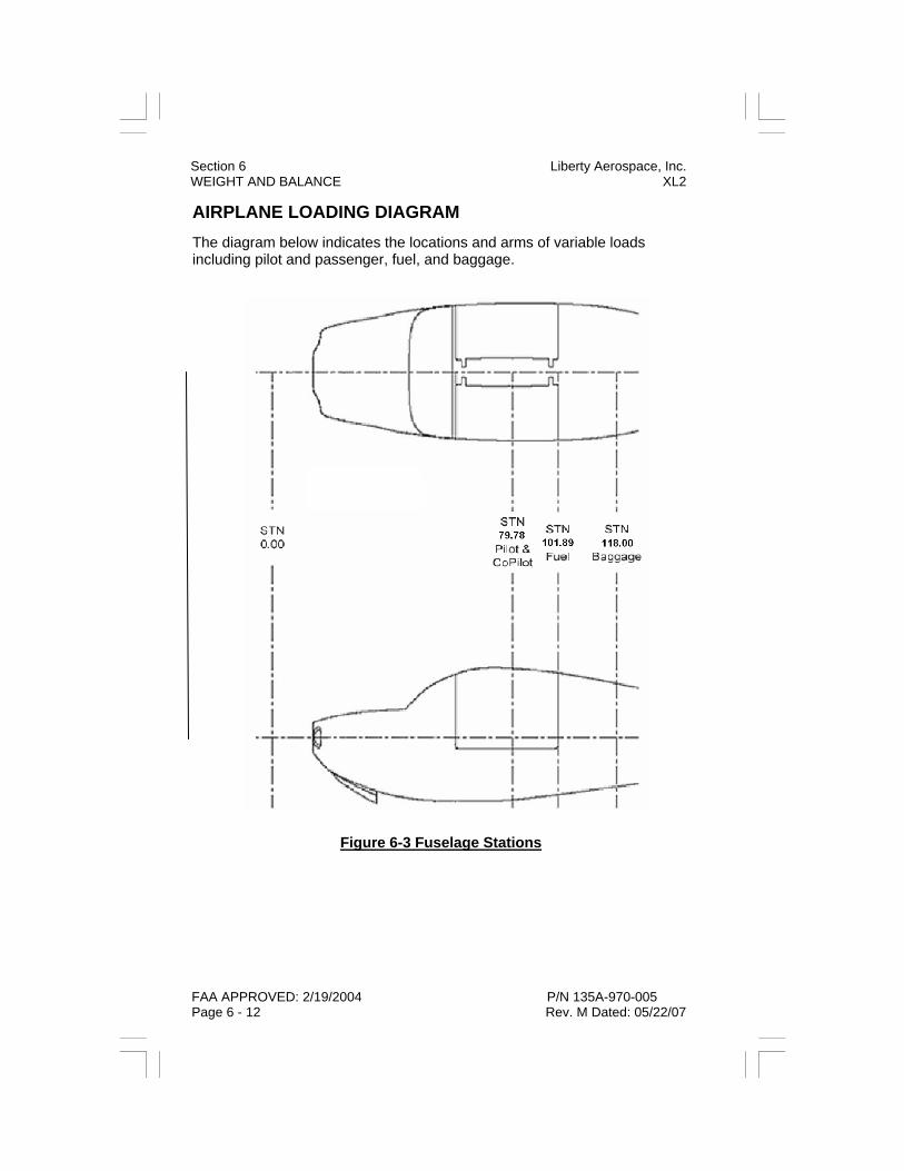
AIRPLANE LOADING DIAGRAM The diagram below indicates the locations and arms of variable loads including pilot and passenger, fuel, and baggage.
Figure 6-3 Fuselage Stations
Section 6 Liberty Aerospace, Inc. WEIGHT AND BALANCE XL2
FAA APPROVED: 2/19/2004 P/N 135A-970-005 Page 6 - 12 Rev. M Dated: 05/22/07

LOADING GRAPH To determine the moment/1000 for the pilot and copilot, fuel, and bag-gage, enter the graph at the actual weight of each item at the left. Read across to the diagonal line for that item (pilot/copilot, fuel, or baggage), then read down to determine the moment/1000.
Figure 6-4 Loading Graph
Liberty Aerospace, Inc. Section 6 XL2 WEIGHT AND BALANCE
P/N 135A-970-005 FAA APPROVED: 2/19/2004 Rev. M Dated: 05/22/07 Page 6 - 13
0
10 0
2 0 0
3 0 0
4 0 0
50 0
0 5 10 15 2 0 2 5 3 0 3 5 4 0
Moment/1000
Wei
ght -
Pou
nds
FUEL
BAGGAGE
PILOT/COPILOT
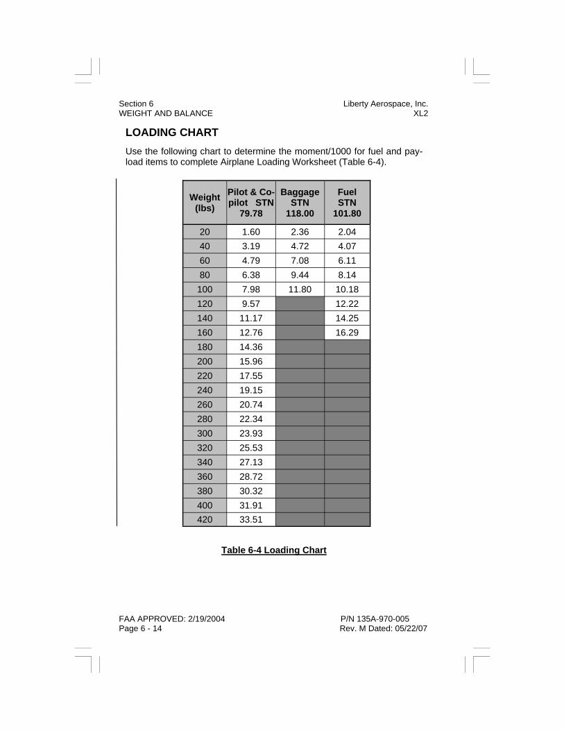
LOADING CHART Use the following chart to determine the moment/1000 for fuel and pay-load items to complete Airplane Loading Worksheet (Table 6-4).
Table 6-4 Loading Chart
Section 6 Liberty Aerospace, Inc. WEIGHT AND BALANCE XL2
FAA APPROVED: 2/19/2004 P/N 135A-970-005 Page 6 - 14 Rev. M Dated: 05/22/07
Weight (lbs)
Pilot & Co-pilot STN
79.78
Baggage STN
118.00
Fuel STN
101.80
20 1.60 2.36 2.04 40 3.19 4.72 4.07 60 4.79 7.08 6.11 80 6.38 9.44 8.14 100 7.98 11.80 10.18 120 9.57 12.22 140 11.17 14.25 160 12.76 16.29 180 14.36 200 15.96 220 17.55 240 19.15 260 20.74 280 22.34 300 23.93 320 25.53 340 27.13 360 28.72 380 30.32 400 31.91 420 33.51

AIRPLANE LOADING WORKSHEET Instructions:
Use the following worksheet to calculate airplane weight and balance prior to each flight. It is recommended that this page be photocopied to provide a supply of loading worksheets. Moments for each item may be calculated (item weight x item arm = item moment/1000) or determined from the graph on page 6-15.
C.G. = Total Moment ÷ Total Weight
Table 6-5 Airplane Loading Worksheet
Use either the “Loaded Airplane Total Moment Limitations” or “Loaded Airplane Center of Gravity (ARM) Limitations” charts on the next two pages to determine that airplane loaded weight and balance are within limitations.
Gal. Weight (lbs)
Arm (in)
Moment (in.lbs.)
Empty Wt 1174 83.20 97676.8
Pilot 79.78
Passenger 79.78
Fuel (6 lbs/gal) 101.80
Baggage (100 lbs
max) 118.00
Total Wt
Total Moment ÷1000
Loaded C.G. Location
Liberty Aerospace, Inc. Section 6 XL2 WEIGHT AND BALANCE
P/N 135A-970-005 FAA APPROVED: 2/19/2004 Rev. M Dated: 05/22/07 Page 6 - 15

LOADED AIRPLANE TOTAL MOMENT LIMITATIONS Use the following chart or table to determine if the weight and moment from the completed Airplane Loading Worksheet (Table 6-4) are within limits.
Figure 6-5 Moment Limits
Moment/1000
Minimum Maximum
1200 99 104 1250 103 108 1300 107 113 1350 111 117 1400 115 121 1450 119 126 1500 123 130 1550 127 134 1600 132 139 1653 138 143
Wt (lbs)
Section 6 Liberty Aerospace, Inc. WEIGHT AND BALANCE XL2
FAA APPROVED: 2/19/2004 P/N 135A-970-005 Page 6 - 16 Rev. G Dated: 5/19/2006
1100
1200
1300
1400
1500
1600
1700
90 100 110 120 130 140 150
Moment/1000
Wei
ght -
Pou
nds

LOADED AIRPLANE CENTER OF GRAVITY (ARM) LIMITATIONS The following chart illustrates the airplane center of gravity envelope as inches from aircraft datum (and as a percentage of MAC).
WEIGHT AND CENTER OF GRAVITY LIMITS
Forward: 82.20 inches aft of datum at 1554 lbs. Mid: 83.48 inches aft of datum at 1653 lbs. Aft: 86.75 inches aft of datum at 1653 lbs.
Figure 6-6 Loaded Airplane C.G. Envelope
Liberty Aerospace, Inc. Section 6 XL2 WEIGHT AND BALANCE
P/N 135A-970-005 FAA APPROVED: 2/19/2004 Rev. G Dated: 5/19/2006 Page 6 - 17

Section 6 Liberty Aerospace, Inc. WEIGHT AND BALANCE XL2
FAA APPROVED: 2/19/2004 P/N 135A-970-005 Page 6 - 18 Initial Release
RECORD OF WEIGHT AND BALANCE CHANGES The following table (photocopy and add pages as necessary) provides a continuous history of changes in structure or equipment affecting weight and balance of this airplane.
Table 6-6 Record of Weight and Balance Changes
Serial Num: Reg. Num: Page of
Date Item No. Description of Article
or Modification
Weight Change Added (+) or Removed (-)
Running Basic Empty Weight
In Out WT LB
ARM IN
MOM/ 1000
WT LB
MOM/ 1000
As Delivered
Section 6 Liberty Aerospace, Inc. WEIGHT AND BALANCE XL2

Liberty Aerospace, Inc. Section 7 XL2 AIRPLANE & SYSTEMS DESCRIPTION
P/N 135A-970-005 FAA APPROVED: 2/19/2004 Rev. C Dated: 7/26/2005 Page 7 - 1
SECTION 7
AIRPLANE & SYSTEMS DESCRIPTION
TABLE OF CONTENTS
Introduction ............................................................................ 7 - 5 Airframe ................................................................................. 7 - 6 Wing Flaps ............................................................................. 7 - 7 Flap Position Switch ........................................................ 7 - 7 Primary Flight Controls .......................................................... 7 - 8 Pitch Control System....................................................... 7 - 8 Roll Control System......................................................... 7 - 9 Yaw Control System...................................................... 7 - 10 Trim System......................................................................... 7 - 11 Pitch Trim Switch and Indicator..................................... 7 - 12 Airplane Cabin / Flight Deck Arrangement .......................... 7 - 13 Entrance Doors / Windows............................................ 7 - 13 Instrument Panel ........................................................... 7 - 14 Center Console ............................................................. 7 - 15 Baggage Compartment ................................................. 7 - 15 Seats ............................................................................. 7 - 16 Reference Eye Position................................................. 7 - 17 Cabin Safety Equipment................................................ 7 - 18 Landing Gear ....................................................................... 7 - 19 Main Gear...................................................................... 7 - 19 Nose Gear ..................................................................... 7 - 19 Brake System ................................................................ 7 - 20 Engine.................................................................................. 7 - 21 FADEC System ............................................................. 7 - 21 FADEC Ignition System................................................. 7 - 25 FADEC Fuel Injection System....................................... 7 - 26 Engine Oil System......................................................... 7 - 28 Engine Cooling .............................................................. 7 - 29

Section 7 Liberty Aerospace, Inc. AIRPLANE & SYSTEMS DESCRIPTION XL2
FAA APPROVED: 2/19/2004 P/N 135A-970-005 Page 7 - 2 Rev. C Dated: 7/26/2005
Engine Air Induction System..........................................7 - 29 Engine Exhaust..............................................................7 - 29 Engine Controls .............................................................7 - 30 Engine Indicating - VM1000...........................................7 - 30 Propeller ...............................................................................7 - 37 Fuel System..........................................................................7 - 38 Fuel Boost Pump and Switch.........................................7 - 39 Fuel Quantity Indicator...................................................7 - 39 Fuel Shutoff Valve..........................................................7 - 39 Fuel Venting...................................................................7 - 40 Electrical System..................................................................7 - 41 Primary Battery ..............................................................7 - 41 Secondary Battery .........................................................7 - 41 Alternator System ..........................................................7 - 43 Master Switch ................................................................7 - 43 Avionics Power Switch...................................................7 - 44 Voltmeter / Ammeter ......................................................7 - 44 ALT FAIL Annunciator....................................................7 - 45 Circuit Breakers and Fuses ...........................................7 - 46 Exterior Lighting....................................................................7 - 47 Interior Lighting.....................................................................7 - 48 Cabin Ventilation ..................................................................7 - 49 Stall Warning System ...........................................................7 - 49 Pitot-Static System ...............................................................7 - 50 Airspeed Indicator ..........................................................7 - 50 Altimeter.........................................................................7 - 50 Vertical Speed Indicator.................................................7 - 51 Pitot Heat Switch............................................................7 - 52 Pitot Heat Light ..............................................................7 - 52 Alternate Static Source ..................................................7 - 52 Avionics and Navigation .......................................................7 - 53 Magnetic Compass ........................................................7 - 53 Attitude Indicator ............................................................7 - 53 Directional Gyro .............................................................7 - 54

Liberty Aerospace, Inc. Section 7 XL2 AIRPLANE & SYSTEMS DESCRIPTION
P/N 135A-970-005 FAA APPROVED: 2/19/2004 Rev. C Dated: 7/26/2005 Page 7 - 3
Turn Coordinator ........................................................... 7 - 54 Audio System ................................................................ 7 - 55 GPS Navigation............................................................. 7 - 56 Communication (COM) Transceiver.............................. 7 - 58 Navigation (NAV) Receiver ........................................... 7 - 58 Transponder .................................................................. 7 - 59 Hour Meter..................................................................... 7 - 59 Digital Clock / OAT ........................................................ 7 - 60 Emergency Locator Transmitter .................................... 7 - 60

Section 7 Liberty Aerospace, Inc. AIRPLANE & SYSTEMS DESCRIPTION XL2
FAA APPROVED: 2/19/2004 P/N 135A-970-005 Page 7 - 4 Rev. C Dated: 7/26/2005
THIS PAGE INTENTIONALLY LEFT BLANK

Liberty Aerospace, Inc. Section 7 XL2 AIRPLANE & SYSTEMS DESCRIPTION
P/N 135A-970-005 FAA APPROVED: 2/19/2004 Rev. C Dated: 7/26/2005 Page 7 - 5
INTRODUCTION
This section describes the construction of the airplane and the construc-tion, layout, and operation of its systems. Some of the equipment de-scribed in this section is optional, and may not be installed in all air-planes. Refer to Section 9 (Supplements) for information on the description and operation of other optional systems or equipment.
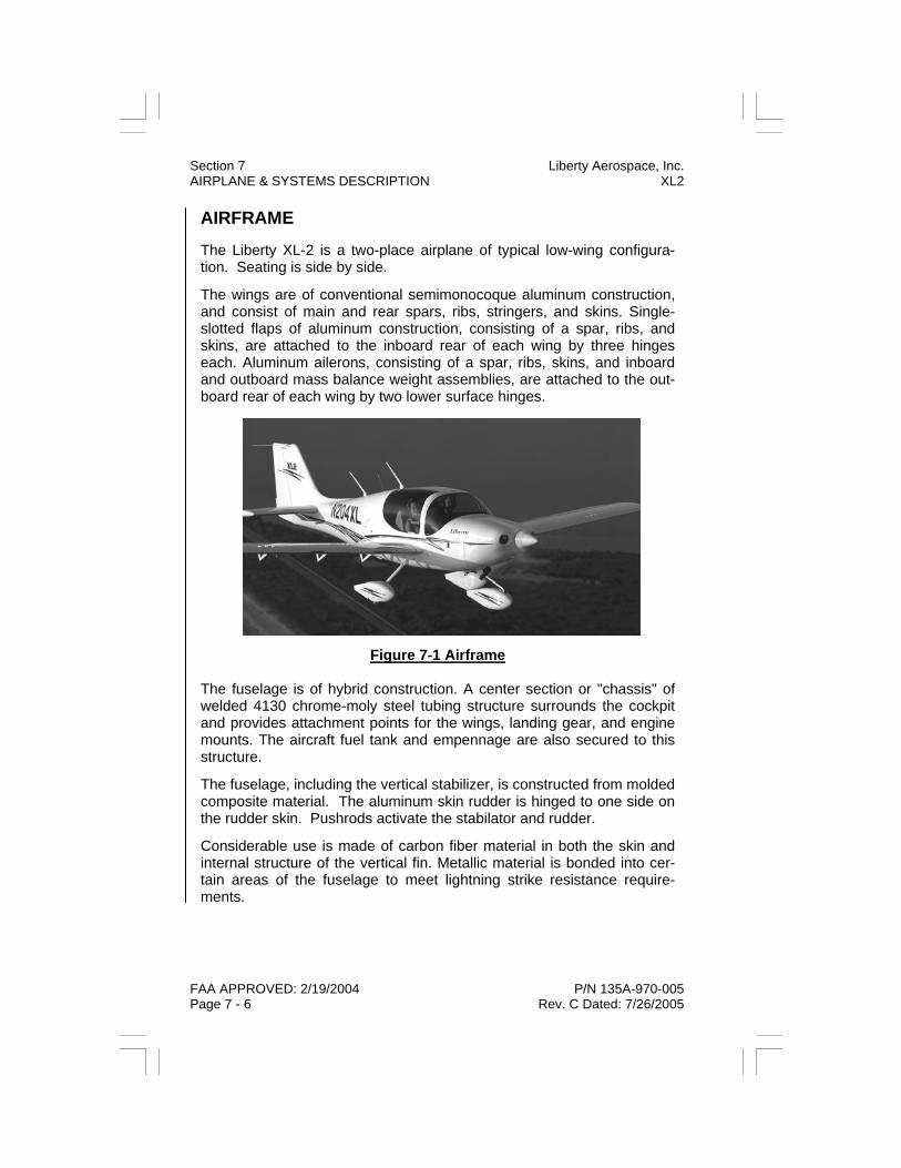
Section 7 Liberty Aerospace, Inc. AIRPLANE & SYSTEMS DESCRIPTION XL2
FAA APPROVED: 2/19/2004 P/N 135A-970-005 Page 7 - 6 Rev. C Dated: 7/26/2005
AIRFRAME
The Liberty XL-2 is a two-place airplane of typical low-wing configura-tion. Seating is side by side.
The wings are of conventional semimonocoque aluminum construction, and consist of main and rear spars, ribs, stringers, and skins. Single-slotted flaps of aluminum construction, consisting of a spar, ribs, and skins, are attached to the inboard rear of each wing by three hinges each. Aluminum ailerons, consisting of a spar, ribs, skins, and inboard and outboard mass balance weight assemblies, are attached to the out-board rear of each wing by two lower surface hinges.
Figure 7-1 Airframe The fuselage is of hybrid construction. A center section or "chassis" of welded 4130 chrome-moly steel tubing structure surrounds the cockpit and provides attachment points for the wings, landing gear, and engine mounts. The aircraft fuel tank and empennage are also secured to this structure.
The fuselage, including the vertical stabilizer, is constructed from molded composite material. The aluminum skin rudder is hinged to one side on the rudder skin. Pushrods activate the stabilator and rudder.
Considerable use is made of carbon fiber material in both the skin and internal structure of the vertical fin. Metallic material is bonded into cer-tain areas of the fuselage to meet lightning strike resistance require-ments.

Liberty Aerospace, Inc. Section 7 XL2 AIRPLANE & SYSTEMS DESCRIPTION
P/N 135A-970-005 FAA APPROVED: 2/19/2004 Rev. R Dated: : 8/18/2009 Page 7 - 7
WING FLAPS
Large single-slotted flaps are installed on each wing. Each is supported by three hinges offset below the wing lower surface. A single electric actuator in the center fuselage operates a cross-tube which, in turn, operates both flaps. It is powered by the airplane primary electrical system via the “FLAPS” circuit breaker.
Figure 7-2 Wing Flaps FLAP POSITION SWITCH
To operate the flaps, a spring loaded, center flap control switch that is located on the avionics panel right side must be held in the "retract" or "extend" position. As flaps move, illuminating one of three indicators above the flap control switch provides position information. Position switches that are located in the flap actuation mechanism activate each indicator. As flaps reach an angle of deflection to be reported, the corre-sponding position switch is depressed, which in turn activates the appro-priate position indicator. As flaps continue to move however, position switch pressure is released extinguishing the indicator. Flap motor op-eration continues as long as flap control switch pressure is held. At flap full extension or full retraction, the actuator disengages permitting actua-tor motor free spool operation for as long as flap control switch pressure is applied. At the end of travel, depending on direction selected, a full extension indicator or full retraction position indicator will be illuminated. For the standard aircraft, flap positions are marked at 0, 10, and 30 de-grees. It is possible to release the flap control switch at each of these positions or any point between. Flaps will hold the position achieved when the flap control switch is released.

Section 7 Liberty Aerospace, Inc. AIRPLANE & SYSTEMS DESCRIPTION XL2
FAA APPROVED: 2/19/2004 P/N 135A-970-005 Page 7 - 8 Rev. C Dated: 7/26/2005
PRIMARY FLIGHT CONTROLS
PITCH CONTROL SYSTEM
The left (pilot) and right (passenger) control sticks are attached to a common control column assembly. Forward and aft movement of the control sticks and column moves the yoke about a center bearing and operates a pushrod which transmits this motion aft (via a "tunnel" through the fuselage-mounted fuel tank) to an idler bell-crank installed aft of the fuel tank below the floor of the baggage compartment. From there, a second pushrod transmits pitch control movement to a control arm attached to the center of the stabilator torque tube, thus rotating the torque tube and stabilators up and down about the center axis of the torque tube. To prevent aerodynamic flutter, the stabilators are mass-balanced by a weight inside the fuselage attached to an arm protruding forward from the stabilizer torque tube.
Figure 7-3 Pitch Control System

Liberty Aerospace, Inc. Section 7 XL2 AIRPLANE & SYSTEMS DESCRIPTION
P/N 135A-970-005 FAA APPROVED: 2/19/2004 Rev. C Dated: 7/26/2005 Page 7 - 9
ROLL CONTROL SYSTEM
Side to side movement of the control sticks and control column rotates a torque tube extending aft to approximately mid-chord of the wings. A bell-crank arm at the aft end of the torque tube changes its rotation to a linear motion of two push rods extending upward and outboard to oper-ate "rocker" bell-cranks installed in the steel tube fuselage center sec-tion. The rockers bear against identical rockers in the wing roots, which transmit the motion, via push rods and bell-cranks, to the left and right ailerons.
Figure 7-4 Roll Control System

Section 7 Liberty Aerospace, Inc. AIRPLANE & SYSTEMS DESCRIPTION XL2
FAA APPROVED: 2/19/2004 P/N 135A-970-005 Page 7 - 10 Rev. C Dated: 7/26/2005
YAW CONTROL SYSTEM
Rudder pedal assemblies are provided for the pilot and copilot seats. Each pedal assembly includes an adjustment crank, located at the bot-tom of the instrument panel on each side of the cockpit, which allows the pedals to be adjusted forward or aft.
Forward and aft movement of either rudder pedal rotates a torque tube extending across the airplane below the instrument panel. A series of links, bell-cranks, and pushrods changes this rotation to linear motion and transmits it aft through the fuselage to the rudder drive arm, moving the rudder left and right in response to pedal inputs.
Figure 7-5 Yaw Control System

Liberty Aerospace, Inc. Section 7 XL2 AIRPLANE & SYSTEMS DESCRIPTION
P/N 135A-970-005 FAA APPROVED: 2/19/2004 Rev. C Dated: 7/26/2005 Page 7 - 11
TRIM SYSTEM
A trim tab is hinged to the rear spar of each horizontal stabilator. These tabs are geared to move in the same direction as the stabilators them-selves, thus providing an "anti-servo" effect and generating consistent pitch control forces for the pilot.
Figure 7-6 Pitch Trim System
The trim tabs are connected, via link rods and a linkage which moves about the stabilator torque tube at the stabilator root rib, to an electric screw-jack actuator in the lower aft fuselage. This allows the pilot to set the neutral or faired position of the trim tabs to correspond with any de-sired angle of the stabilators, thus providing an aircraft pitch trim func-tion.

Section 7 Liberty Aerospace, Inc. AIRPLANE & SYSTEMS DESCRIPTION XL2
FAA APPROVED: 2/19/2004 P/N 135A-970-005 Page 7 - 12 Rev. C Dated: 7/26/2005
Figure 7-7 Trim Tab
PITCH TRIM SWITCH AND INDICATOR
The actuator is controlled by a switch on the cockpit center console. The switch is labeled “NOSE DOWN” and “NOSE UP”. An indicator on the center console displays trim position to the pilot. With the stabilator held neutral, pressing NOSE DOWN on the switch causes the trailing edge of the anti-servo tab to rise and the indicator needle to move forward.
In the event of trim malfunction, out-of-trim forces are such that the air-plane can be safely landed without undue effort or pilot skill require-ments, even if mis-trimmed to the full nose-up or nose-down position.
Figure 7-8 Pitch Trim Switch

Liberty Aerospace, Inc. Section 7 XL2 AIRPLANE & SYSTEMS DESCRIPTION
P/N 135A-970-005 FAA APPROVED: 2/19/2004 Rev. R Dated: : 8/18/2009 Page 7 - 13
Liberty Aerospace, Inc. Section 7 XL2 AIRPLANE & SYSTEMS DESCRIPTION
AIRPLANE CABIN / FLIGHT DECK ARRANGEMENT
ENTRANCE DOORS / WINDOWS
A single large combination entrance door and window on each side pro-vides access to the cockpit. The doors are top-hinged, swinging upward to open. Integral gas springs aid in opening the doors and hold them in the open position.
Forward and aft door latch pins in the doors engage pin bushings in the fuselage. They are operated by an interior door handle on either side, and by an exterior door handle on each side.
Each door incorporates an operable vent window. The vent window may be opened at speeds of 50 knots or less for increased ventilation. En-sure door vent window is closed prior to operating door mechanism.
WARNING Verify both doors are securely latched, with forward and aft pins in bushings, by pushing on aft section of door. Unlatching a door in-flight will result in possible departure of the door from the air-craft, with potential damage to the stabilizer and loss of control. If door opens in-flight refer to door open in flight procedure in Sec-tion 3 – emergency procedures and land as soon as practical.
Figure 7-9 Entrance Doors / Windows

Section 7 Liberty Aerospace, Inc. AIRPLANE & SYSTEMS DESCRIPTION XL2
FAA APPROVED: 2/19/2004 P/N 135A-970-005 Page 7 - 14 Rev. C Dated: 7/26/2005
INSTRUMENT PANEL
The XL2 instrument panel is subdivided into the upper left area, which contains the flight instruments (pitot-static and gyro instruments); the lower left area, containing essential switches and the integrated engine instrument display system, described later in this section; center areas, containing the avionics “stack,” the circuit breaker panel, and the cockpit center console, containing the throttle, brake levers, trim control switch and indicator, and fuel shutoff valve.
The six primary flight instruments are installed in the “standard T” ar-rangement directly in-front of the pilot. The arrangement comprises six primary instruments: airspeed indicator, attitude indicator, altimeter, turn coordinator, directional gyro (heading indicator), and vertical speed indi-cator. The picture below is for reference only and is not intended to rep-resent actual locations or availability of equipment shown.
Figure 7 - 10 Instrument Panel / Center Console

Liberty Aerospace, Inc. Section 7 XL2 AIRPLANE & SYSTEMS DESCRIPTION
P/N 135A-970-005 FAA APPROVED: 2/19/2004 Rev. C Dated: 7/26/2005 Page 7 - 15
CENTER CONSOLE
The center console panel, a small angled panel, directly below the avi-onics stack, accommodates the fuel pump mode switch, engine alternate induction air control, and trim indicator.
The center console between the pilot and passenger seat contains the throttle lever, two brake levers (for left and right wheel brakes) incorpo-rating a parking brake device, the electric pitch trim switch and indicator, and the emergency fuel shutoff valve.
BAGGAGE COMPARTMENT
The baggage compartment is contiguous with the passenger cabin, and extends from aft of the seatbacks to the rear baggage compartment bulkhead. The seat backs are sculpted to allow ease of access to the 4’ x 3’ x 2’ baggage area. Maximum allowable baggage weight is 100 pounds. The loads should be distributed over the baggage bay area at a maximum 29 lbs/ft2. Reduced weights may be required to conform to aircraft weight and balance limitations.
NOTE It is the pilot’s responsibility to ensure the baggage bay is loaded at and around the center of gravity (refer to Section 6 - Weight and Bal-ance).

Section 7 Liberty Aerospace, Inc. AIRPLANE & SYSTEMS DESCRIPTION XL2
FAA APPROVED: 2/19/2004 P/N 135A-970-005 Page 7 - 16 Rev. C Dated: 7/26/2005
SEATS
The XL2’s seats are integral to the fuselage structure, and are not ad-justable. (The pilot and copilot rudder pedals are adjustable, in-flight or on the ground.) The cushions are secured to the seats by hook-and-loop (“Velcro”) fasteners. Ensure cushions do not obstruct flight controls.
Figure 7-11 Seats / Baggage Compartment

Liberty Aerospace, Inc. Section 7 XL2 AIRPLANE & SYSTEMS DESCRIPTION
P/N 135A-970-005 FAA APPROVED: 2/19/2004 Rev. C Dated: 7/26/2005 Page 7 - 17
REFERENCE EYE POSITION
The pilot is to establish, through seat cushion position adjustment, and rudder pedal adjustment, the reference eye position, which ensures a sufficiently extensive, clear and undistorted view enabling the pilot to safely taxi, takeoff, approach, land, and perform any maneuvers within the operating limitations of the airplane.
It is essential that the pilot, while strapped in the seat, establishes the sitting eye height which offers an unobstructed view down to the vertical lower display screen of the VM1000; next, up to a line-of-sight across the instrument panel’s sloped top surface, through the windscreen, and over the nose of the aircraft. Due to the obvious importance in approach and landing and the fact that it is in the direction of flight, emphasis should be placed on establishing the sitting eye height for over-the-nose vision, especially for shorter pilots.
In addition to the above, an acceptable sitting eye height ensures that vision inside the cockpit is not obstructed by the glare shield, control stick, throttle, or knees, and that the pilot’s external vision extends with-out obstruction straight ahead, over the nose of the aircraft to the ground, then upward to under the canopy bow.
Figure 7-12 Reference Eye Position

Section 7 Liberty Aerospace, Inc. AIRPLANE & SYSTEMS DESCRIPTION XL2
FAA APPROVED: 2/19/2004 P/N 135A-970-005 Page 7 - 18 Rev. C Dated: 7/26/2005
CABIN SAFETY EQUIPMENT
Seatbelts / Shoulder Harness
Seat belts and dual shoulder harnesses are provided for each seat. The seat belts are secured to the aircraft structure on either side of the seat. The dual shoulder harness straps for each seat are joined and secured to a single fitting in the seatback structure directly behind each seat.
Each seat belt has a standard “lift-to-release” metal-to-metal buckle. Adjusters on each belt allow it to be tightened, and to place the buckle at an approximate central location.
The left and right shoulder harness straps for each seat have buckles to adjust for pilot comfort and asymmetric end fittings. To fasten the shoul-der harness, slide both fittings over the “tongue” of the seat belt buckle end, and then fasten the seat belt. When the shoulder harness fittings are properly aligned, the harness straps should not cross above the seat belt buckle.
Emergency Egress Hammer / Fire Extingusher
If the doors cannot be opened during an emergency egress, utilize the safety hammer which is located in the passenger’s seat back storage compartment and is within easy reach of the pilot-in-command. The safety hammer can be used to smash out enough of the canopy door to exit the aircraft. Another standard feature in the XL2 is the fire extin-guisher, mounted behind the passenger’s seat within easy reach of the pilot located in the left seat.

Liberty Aerospace, Inc. Section 7 XL2 AIRPLANE & SYSTEMS DESCRIPTION
P/N 135A-970-005 FAA APPROVED: 2/19/2004 Rev. C Dated: 7/26/2005 Page 7 - 19
LANDING GEAR
MAIN GEAR
The XL2 has fixed tricycle landing gear. The main gear legs are fabri-cated from heat-treated aluminum alloy and incorporate an internal ma-chined brake line. They are fastened to the fuselage center section by saddle fittings, bolts, and bushings. Either main landing gear assembly can be removed from the airplane without affecting the opposite main gear.
The 5.00 x 5 main gear wheels are installed steel axles. Each incorpo-rates a hydraulic disk brake. Aerodynamic wheel fairings (optional) can be installed one each main landing gear assembly. Normal tire pressure is 50 psi.
NOSE GEAR
The nose landing gear leg is fabricated from heat-treated steel. It is se-cured to the fuselage center section by a bushing and a bolt. It may be removed from the airplane without affecting the main landing gear.
The nose wheel is 5.00 x 5; normal tire pressure is 50 psi. The nose wheel assembly is installed in an aluminum casting, which is secured to the nose gear leg via a ball bearing (the “caster” bearing) to allow rota-tion up to 80 degrees left or right for nose wheel steering. A stack of six spring-steel washers provides a constant force that applies to the friction dampener located on the nose wheel. An aerodynamic wheel fairing of composite material may be installed on the nose landing gear.
Ground steering of the XL2 is achieved by differential application of the left and right main landing gear brakes. Either (or both) brake(s) may be applied and controlled by modulating rearward finger pressure on the brake lever(s).

Section 7 Liberty Aerospace, Inc. AIRPLANE & SYSTEMS DESCRIPTION XL2
FAA APPROVED: 2/19/2004 P/N 135A-970-005 Page 7 - 20 Rev. C Dated: 7/26/2005
BRAKE SYSTEM
Individual disk brakes are installed on each main landing gear wheel. They are operated by individual master cylinders installed in the cockpit center console. Brake lines extend from each master cylinder to the inboard ends of the main landing gear legs; integral passages machined into the gear legs, and short flexible lines at the outboard ends of the gear legs, supply brake fluid under pressure to the brake calipers. Two brake levers are installed in the center console. To operate the brakes, pull either or both levers aft.
A ratchet type parking brake lever is installed in the center console be-tween the brake levers. To apply the parking brake, pull both brake lev-ers firmly aft, then pull the center parking brake lever aft and release the left and right brake levers. To release the parking brake, pull both brake levers firmly aft and allow the parking brake lever to spring forward.
Brake fluid is stored in a common reservoir for both master cylinders, located on starboard side of the engine bay aft of the firewall. Remove upper cowling for access to service the reservoir with MIL-H-5606 type hydraulic fluid.
Figure 7-13 Brake System
Liberty Aerospace, Inc. Section 7 XL2 AIRPLANE & SYSTEMS DESCRIPTION
P/N 135A-970-005 FAA APPROVED: 2/19/2004 Rev. C Dated: 7/26/2005 Page 7 - 21
ENGINE
The XL2 is powered by a Teledyne Continental IOF-240-B, Full Authority Digital Engine Control (FADEC) equipped, four-cylinder, horizontally-opposed, air-cooled, naturally-aspirated, fuel-injected engine rated at 125 HP at 2800 RPM.
FADEC SYSTEM
The engine is equipped with a Full Authority Digital Engine Control (FADEC) System for continuously monitoring and controlling ignition timing, fuel injection timing, and fuel mixture. The microprocessor-based FADEC system monitors engine operating conditions and then automati-cally sets the fuel mixture and ignition timing accordingly for any given power setting. Consequently, the FADEC equipped engine does not require magnetos and eliminates the need for a manual fuel/air mixture control.
The FADEC System provides control in both specified operating condi-tions and fault conditions. The system is designed to prevent adverse changes in power or thrust. In the event of loss of primary aircraft-supplied power, the engine controls continue to operate using a Secon-dary Power Source (SPS). As a control device, the system performs self-diagnostics to determine overall system status and conveys this in-formation to the pilot by various indicators on the Health Status Annun-ciator (HSA) panel.
The FADEC System is able to withstand storage temperature extremes and operate at the same capacity as a non-FADEC equipped engine in extreme heat, cold, and high humidity environments.
The basic components of the FADEC System include: Two Electronic Control Units (ECUs), Health Status Annunciator (HSA) (panel installed in the cockpit), and FADEC Sensor Set.

Section 7 Liberty Aerospace, Inc. AIRPLANE & SYSTEMS DESCRIPTION XL2
FAA APPROVED: 2/19/2004 P/N 135A-970-005 Page 7 - 22 Rev. C Dated: 7/26/2005
Electronic Control Units (ECU)
An Electronic Control Unit (ECU) is assigned to a pair of engine cylin-ders. Since the engine has four cylinders, there are two ECUs, one unit for every pair of cylinders. The ECUs control the fuel mixture and spark timing for respective engine cylinders; ECU 1 controls opposing Cylin-ders 1 and 2; ECU 2 controls Cylinders 3 and 4.
Each ECU is divided into upper and lower portions. The lower portion contains an electronic circuit board; the upper portion houses the ignition coils. The electronic circuit board contains two, independent microproc-essor controllers which serve as control channels. During engine opera-tion, one control channel is assigned to operate a single engine cylinder. Therefore, one ECU can control two engine cylinders, one control chan-nel per cylinder.
The control channels are independent and there are no shared elec-tronic components between the control channel pair within one ECU. However, if a control channel fails, the other control channel in the pair within the same ECU is capable of operating both its assigned cylinder and the other opposing engine cylinder as backup control for fuel injec-tion and ignition timing.
Each channel controls its assigned cylinder in a manner that will yield optimum performance for the current operating conditions to prevent exceeding normal operating parameters. The fuel mixture may be en-riched or leaned and ignition timing may be retarded to minimize the ex-tent of limit excursion for the given parameter. In this respect, a FADEC-controlled engine is different from a non-FADEC engine in that an indi-vidual cylinder can be leaned or enriched by its control channel without affecting the other cylinders.
Figure 7-14 Electronic Control Unit (ECU)

Liberty Aerospace, Inc. Section 7 XL2 AIRPLANE & SYSTEMS DESCRIPTION
P/N 135A-970-005 FAA APPROVED: 2/19/2004 Rev. C Dated: 7/26/2005 Page 7 - 23
Health Status Annunciator (HSA)
The Health Status Annunciator (HSA) is located on the primary instru-ment panel towards the right side, above the electrical switches and air-craft annunciator lights. The HSA provides indications of primary or sec-ondary (emergency) power malfunctions, erroneous sensor indications, fuel pump malfunctions, and possible misfiring cylinders.
Each HSA annunciator light is associated with a specific system condi-tion. Illumination of a given light indicates that the associated condition has been detected and some response by the pilot may be necessary. In the event annunciator illumination occurs, follow the steps in Chapter 3 - Emergency Procedures for the specific indication.
Illumination of the FADEC CAUTION light indicates pressure or tem-perature sensor failures, abnormal pressure or temperature above limits, misfire/cylinder not firing, or cylinder not enabled (ignition switch OFF or not in BOTH position).
Illumination of the FADEC WARN light indicates that more than one cyl-inder is faulted. The FADEC WARN light is always preceded and/or ac-companied by illumination of the FADEC CAUTION light.
The EBAT FAIL light illuminates when there is a fault condition with the backup (secondary) power supply. The charging current into the backup battery is too high, indicating: low charge, bad battery, the wire charging the backup battery is not connected, or the primary power source is off or has failed.
Illumination of the PPWR FAIL light indicates that the FADEC system is drawing power from the backup power supply because the primary elec-trical power supply has been interrupted, the backup power supply po-tential is higher than the primary buss or the primary power source is off or has failed.
Refer to Section 3 - Emergency Procedures and Section 4 - Normal Pro-cedures for explanation of FUEL PUMP indications.
Figure 7-15 Health Status Annunciator (HSA)
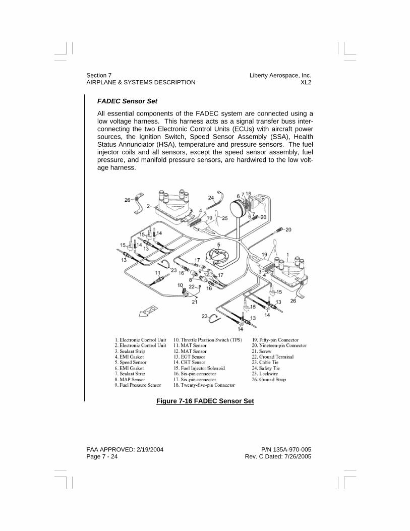
Section 7 Liberty Aerospace, Inc. AIRPLANE & SYSTEMS DESCRIPTION XL2
FAA APPROVED: 2/19/2004 P/N 135A-970-005 Page 7 - 24 Rev. C Dated: 7/26/2005
FADEC Sensor Set
All essential components of the FADEC system are connected using a low voltage harness. This harness acts as a signal transfer buss inter-connecting the two Electronic Control Units (ECUs) with aircraft power sources, the Ignition Switch, Speed Sensor Assembly (SSA), Health Status Annunciator (HSA), temperature and pressure sensors. The fuel injector coils and all sensors, except the speed sensor assembly, fuel pressure, and manifold pressure sensors, are hardwired to the low volt-age harness.
Figure 7-16 FADEC Sensor Set

Liberty Aerospace, Inc. Section 7 XL2 AIRPLANE & SYSTEMS DESCRIPTION
P/N 135A-970-005 FAA APPROVED: 2/19/2004 Rev. C Dated: 7/26/2005 Page 7 - 25
FADEC IGNITION SYSTEM
The ignition system of the IOF-240-B engine is part of the FADEC. Unlike conventional magneto ignition systems, its timing is electronically determined by the FADEC computers. The ignition subsystem of the FADEC is not self-powered, but requires an adequate supply of DC power from the airplane electrical system.
To provide necessary system redundancy, the FADEC has two power sources. In the airplane, the primary power source, labeled FADEC A, is the airplane’s main power distribution bus, which is powered by the alter-nator and/or the airplane’s primary battery.
The secondary power source, labeled FADEC B, is powered by a sepa-rate battery. When the airplane’s main power distribution bus is ener-gized, a charging circuit constantly recharges the FADEC B battery, thus indirectly powering the FADEC B bus.
In the event of failure of the airplane primary DC system, including dis-charge of the primary battery, the secondary battery will power the FADEC, via the FADEC B connection, for a period sufficient to locate and land at a suitable airport.
WARNING Engine may continue to operate normally from the emergency battery for up to 60 minutes if the battery is properly maintained and fully charged. Plan to land well within 60 minutes from illumination of EBAT FAIL and PPWR FAIL annunciators.
The FADEC is fully operational when powered by the FADEC A bus, the FADEC B bus, or both. Switches are provided to check operation on both systems before flight. PPWR FAIL and EBAT FAIL captions on the FADEC Health Status Annunciator illuminate to confirm operation of the FADEC from either or both power sources.

Section 7 Liberty Aerospace, Inc. AIRPLANE & SYSTEMS DESCRIPTION XL2
FAA APPROVED: 2/19/2004 P/N 135A-970-005 Page 7 - 26 Rev. C Dated: 7/26/2005
FADEC FUEL INJECTION SYSTEM
Fuel from the airframe fuel system is routed to the intake of the engine-driven fuel pump, which is mounted on the front left side of the engine and gear-driven from the camshaft.
Fuel entering the engine driven pump passes through a centrifugal separator, where fuel vapor is removed and returned to the airplane fuel tank. Next, it passes into the pump element, where its pressure is in-creased. Since pump effectiveness varies with engine speed, the pump is designed to produce more pressure and flow than is required by the engine fuel injectors.
An adjustable relief valve regulates pump output at lower RPM, while an adjustable internal orifice regulates pressure at high RPM. These ad-justments are critical to proper function of the FADEC system.
Fuel pressure is displayed on the VM-1000FX Integrated Engine Instru-ment System, or can be checked by connecting a portable (“laptop”) computer to the data output of the FADEC system. Diagnostic software and the required connecting cable are available from Teledyne Conti-nental Motors (TCM).

Liberty Aerospace, Inc. Section 7 XL2 AIRPLANE & SYSTEMS DESCRIPTION
P/N 135A-970-005 FAA APPROVED: 2/19/2004 Rev. C Dated: 7/26/2005 Page 7 - 27
Figure 7-17 FADEC Fuel Injection System
FUEL PUMP
FUEL PUMP OUTLETPRESSURE
FUEL INLET FROMAIRCRAFT SUPPLY
RETURN TOAIRCRAFT SUPPLY
LEGEND
VARIABLE PULSEWIDTHCONTROLS AMOUNT OF FUEL
CONTROL PULSE FROMFADEC MPC
FUEL INJECTORNOZZLE
FUEL PRESSURESENSORS
FUEL DISTRIBUTIONBLOCK
20 MICRONFILTER
10 MICRONFILTER

Section 7 Liberty Aerospace, Inc. AIRPLANE & SYSTEMS DESCRIPTION XL2
FAA APPROVED: 2/19/2004 P/N 135A-970-005 Page 7 - 28 Rev. C Dated: 7/26/2005
ENGINE OIL SYSTEM
Engine oil is stored in a pressed-steel tank (sump) of 6-quart capacity, attached to the bottom of the engine crankcase. An oil filler tube, with a filler cap incorporating an oil dipstick, is installed on the oil tank. The gear-type engine oil pressure pump is located at the rear of the engine, with its pickup tube extending into the oil tank. It is driven by the engine camshaft drive gear.
Oil leaves the oil pump under pressure. A regulating valve allows some oil to return to the oil tank to maintain oil pressure within limits at varying engine speeds. Oil from the pump is routed to an oil filter and oil cooler adapter on the left side of the engine accessory case.
The oil cooler routes oil to the externally mounted oil cooler, which incor-porates a “Vernatherm” thermostatically controlled valve to control oil temperature, and to the oil filter element. An integral bypass valve will open in the event of blockage of the oil cooler or oil filter. The oil tem-perature sensor for the engine instruments is also located on the oil cooler adapter. The oil pressure sensor is mounted on the firewall and plumbed to the engine.
Oil galleries and drilled passages inside the engine route oil to the crankshaft and camshaft main bearings and to the hydraulic valve lifters. Drillings inside the crankshaft route oil to the connecting rod lower bear-ings. Oil escaping from the main and connecting rod bearings creates an oil mist inside the crankcase that lubricates the connecting rod upper bearings and cylinder walls, as well as the cam lobes and lower faces of the lifters. In addition, oil nozzles on the main bearings direct a jet of oil at the undersides of the pistons to cool them.
Oil in the hydraulic lifters is routed via the hollow valve pushrods to the cylinder rocker boxes, where it lubricates the rockers, valve stems, and valve guides before returning, via the pushrod housings, to the crank-case. Any excess oil in the crankcase returns, via the large-diameter opening between the crankcase and the sump, to the oil sump.

Liberty Aerospace, Inc. Section 7 XL2 AIRPLANE & SYSTEMS DESCRIPTION
P/N 135A-970-005 FAA APPROVED: 2/19/2004 Rev. C Dated: 7/26/2005 Page 7 - 29
ENGINE COOLING
Air enters the engine cowling through inlets on either side of the propel-ler. Baffles between the cylinders, forward of the front cylinders, and ver-tically behind the rear cylinders force this high-pressure, low temperature air through the cylinder and cylinder head cooling fins. A duct in the rear baffle directs high-pressure, low temperature air to the firewall-mounted oil cooler.
Low-pressure warm air leaves the engine compartment via an opening at the rear of the lower cowling, forward of the firewall. Oil cooler ex-haust air is also discharged at this location.
ENGINE AIR INDUCTION SYSTEM / ALTERNATE AIR CONTROL
Air at ambient temperature is admitted through an air filter assembly in-corporating an oil-saturated textile filter element to trap and remove dust and other foreign material, located above the right-side cylinders. In case this filter becomes blocked or iced, pilot selection of alternate air admits warm unfiltered air from the heater muff around the engine ex-haust. The alternate air control is a pull-push knob located in the lower left center console.
ENGINE EXHAUST
The exhaust system includes individual exhaust pipes from each cylin-der and a single muffler located below the engine. A single overboard discharge pipe extends through the right side of the lower cowling.
The exhaust pipes from each side of the engine are connected to the left and right ends of the muffler, which is cylindrical in shape and which is installed below the engine with its axis running across the airplane. Slip joints in the exhaust pipe accommodate the dimensional changes that result from temperature changes in the exhaust system. Clamps secure the exhaust pipes to the muffler.
A single discharge pipe extends downward and to the (airplane’s) right from the muffler for overboard discharge of exhaust gases.

Section 7 Liberty Aerospace, Inc. AIRPLANE & SYSTEMS DESCRIPTION XL2
FAA APPROVED: 2/19/2004 P/N 135A-970-005 Page 7 - 30 Rev. C Dated: 7/26/2005
ENGINE CONTROLS
Engine operation is controlled by a single throttle lever in the cockpit center console. It operates in the conventional sense: moving the lever forward increases engine power.
Additional engine controls include a conventional key-type ignition switch with OFF, R, L, BOTH, and a spring-loaded START position, and two lever-lock type switches to control primary and secondary power to the FADEC system.
The Teledyne Continental Motors IOF-240B engine installed in the Lib-erty XL2 is equipped with a “PowerLink (tm)” Full Authority Digital En-gine Control system (FADEC) manufactured by the Aerosance Corpora-tion.
This system controls both ignition and fuel delivery functions for the en-gine, thus replacing conventional components such as magnetos (ignition) and carburetor or typical fuel injection system (fuel delivery). Advantages of the FADEC system include digitally controlled and opti-mized spark timing and duration and digitally controlled fuel delivery to each cylinder. FADEC incorporates closed-loop feedback for each indi-vidual cylinder to maximize both power output and fuel economy. In ad-dition, the FADEC provides single-lever power control and optimized engine parameters for all operating modes including startup, idle, take-off, climb, cruise, descent, and landing.
ENGINE INDICATING - VM1000
All engine instruments in the Liberty XL2 are consolidated onto the VM1000, a single electronic display on the lower left instrument panel. They include RPM, percent power, manifold pressure, oil pressure and oil temperature, fuel pressure, electrical system voltage and alternator output amperage, and individual graphic display of exhaust gas tem-perature (EGT) and cylinder head temperature (CHT) for each cylinder. The engine instrument display is powered by the airplane primary electri-cal system via the “VM1000FX” circuit breaker.
Five push buttons (buttons 1 through 5, from left to right) below the dis-play panel control various functions. The VM1000FX will provide the pilot a “flashing signal” signifying an out-of-limits condition for any engine parameter that it monitors.

Liberty Aerospace, Inc. Section 7 XL2 AIRPLANE & SYSTEMS DESCRIPTION
P/N 135A-970-005 FAA APPROVED: 2/19/2004 Rev. C Dated: 7/26/2005 Page 7 - 31
Tachometer
The tachometer system provides both a full sweep graphic analog dis-play and a four place digital display. Color range marks provide a quick reference to monitor normal, caution and red line engine RPM. The dig-its in the center of the tachometer read engine speed with a resolution of 1 RPM. Allow about 3 seconds for RPM indications to stabilize after RPM changes.
A warning alert activates whenever the engines redline is reached. The RPM display will flash until this condition is corrected. When the engine is not running, the tachometer digital display reads the total accumulated engine hours to a maximum of 5999.9 hours. Engine hours are accumu-lated any time RPM is greater than 1500.
Figure 7-18 Engine Indicating - VM1000
Section 7 Liberty Aerospace, Inc. AIRPLANE & SYSTEMS DESCRIPTION XL2
FAA APPROVED: 2/19/2004 P/N 135A-970-005 Page 7 - 32 Rev. C Dated: 7/26/2005
Percent Power
Percent power is displayed by both a full sweep graphic display and a digital display. The digital display also gives a numeric reading of per-cent power. The color range marks provide a quick reference to monitor changes in power. Percent power information is useful during all stages of flight and can be used as a guide when setting cruise power.
The percent power gauge shows the current power output of the engine in percentage of brake horsepower. The range of the indicator is 0 - 100. The maximum percent power is 100 and a warning will activate whenever this value is reached or exceeded.
Manifold Pressure Gauge
The manifold pressure system provides both a full sweep graphic analog display and a three place digital display with resolution to 0.1 in. Hg. The full sweep graphic display resolution is 1" in. Hg. The color range marks provide a quick reference to manifold pressure when making rapid power changes.
Oil Pressure and Temperature
Both oil pressure and oil temperatures are displayed continuously in two separate full sweep graphic and digital areas.
As oil pressure rises, the graph size increases proportionately. The digi-tal display reads out in 1 PSI increments to a maximum of 99. A warning alert activates whenever the engine’s oil pressure redline is reached. The display will flash until this condition is corrected.
Oil temperature is displayed both graphically and digitally. As oil tem-perature rises, the graph size increases proportionately. The digital dis-play reads out in 1 degree Fahrenheit increments to a maximum of 300 degrees. If the oil temperature rises above redline, the system captures the event and the display is flashed until the problem is corrected.

Liberty Aerospace, Inc. Section 7 XL2 AIRPLANE & SYSTEMS DESCRIPTION
P/N 135A-970-005 FAA APPROVED: 2/19/2004 Rev. C Dated: 7/26/2005 Page 7 - 33
Cylinder Analyzer Operation - CHT and EGT
The engine analyzer system displays all cylinder information (cylinder head temperature and exhaust gas temperature) both graphically and digitally and is referred to as the diamond graph display. Color refer-ence marks are provided for cylinder head green, yellow, and redline temperatures.
The default mode for the diamond graph display is the normal mode. In this mode the system displays CHT between the green, yellow and red range marks, left to right, cylinders 1 through 4. EGT graphics are dis-played above the CHT redline marks. A defective CHT or EGT probe will leave the respective graph blank. A flashing CHT graph indicates a cylinder is too hot or is being shock cooled. The high resolution mode is selected by pressing button 1 while in the normal mode. In this mode the entire diamond graph display is tempo-rarily used for high resolution monitoring of EGT. The display can be returned to the normal mode by pressing button 1 again. Notice that left and right brackets appear on the sides of the graphs when in high reso-lution mode.
The digital display shows the temperatures for each EGT and CHT pair and periodically shows the cylinder number (i.e. E1 C1). A warning message is shown if a cylinder has reached red line temperature (i.e. H2 for hot cylinder 2), or is being shock cooled (i.e. C3 for cooled cylinder 3). The default for the digital display is peak display mode (i.e. P1 means cylinder 1 EGT is the hottest, H3 means cylinder 3 CHT is the hottest). Select any combination by pressing button 2 as described be-low.
Display Mode Cylinder Numbers Probes Displayed Cyl. 1 Pair E1 C1 EGT 1 & CHT 1 Cyl. 2 Pair E2 C2 EGT 2 & CHT 2 Cyl. 3 Pair E3 C3 EGT 3 & CHT 3 Cyl. 4 Pair E4 C4 EGT 4 & CHT 4 Peak Mode P# C# Max EGT/CHT (Highest EGT and CHT may not be from the same cylinder)

Section 7 Liberty Aerospace, Inc. AIRPLANE & SYSTEMS DESCRIPTION XL2
FAA APPROVED: 2/19/2004 P/N 135A-970-005 Page 7 - 34 Rev. C Dated: 7/26/2005
Electrical System Monitoring
The VM1000 displays volts and amps both graphically and digitally. Color range marks provide a reference for levels. For a more detailed description of the operation of the voltmeter and ammeter, refer to Elec-trical System later in this section.
VM1000 Autotrack System Operation
The 'Autotrack' system is designed to reduce pilot workload by monitor-ing engine parameters for deviations. Subtle changes may occur in en-gine parameters that can precede major problems. 'Autotrack' provides automatic alerts if such changes occur, allowing the pilot to analyze the situation and take appropriate action.
When to use 'Autotrack':
• Climb - Activate during climb to alert periodically as CHT and/or Oil Temperature increases.
• Cruise - Activate during cruise to alert if any parameter begins
to drift from the selected starting point. • Descent - Activate during descent to alert to increasing
manifold pressure. How to use 'Autotrack':
Step 1. STABILIZE the aircraft. Set up desired power (RPM and manifold pressure). Allow the engine time to stabilize (i.e., engine temps and pressures, etc.).
Step 2. Press 'BUTTON 3'. The 'Autotrack' indicator will activate
in the display and the system will begin tracking the engine's performance from this point.
The 'Autotrack' system is now armed and monitoring for engine deviation from the values present when it was activated. To cancel, simply press 'BUTTON 3' again to extinguish the 'Autotrack' indicator. Re-arm again at any time.
NOTE Any important alert condition, (i.e., low oil pressure, high CHT, etc.) automatically cancels 'Autotrack' mode.

Liberty Aerospace, Inc. Section 7 XL2 AIRPLANE & SYSTEMS DESCRIPTION
P/N 135A-970-005 FAA APPROVED: 2/19/2004 Rev. C Dated: 7/26/2005 Page 7 - 35
'Autotrack' alert indications:
If any engine parameter deviates beyond the initial set point, the system will flash the corresponding graphic display and the 'AUTOTRACK' indi-cator.
If the deviation is large enough, a graphic pointer (circular sweep dis-plays only) will show where the parameter was before the deviation oc-curred. This allows the pilot to evaluate the magnitude of the deviation and take appropriate action.
To shut off the alert condition, return the parameter to its previous value (example: adjusting manifold pressure due to a climb) or simply press 'BUTTON 3' to shut off the ‘AUTOTRACK’ system.
VM1000 Flight Data Recorder System Operation
The integrated engine instrument display incorporates a Flight Data Recorder that stores certain engine operating parameters for each flight.
Data may be retrieved from the Flight Data Recorder in-flight or after shutdown. It will be retained, even when the airplane electrical power is removed, until overwritten by the next flight.
Minimum and maximum values are automatically recorded during the flight and can be reviewed at any time before the next flight. Actual time the engine is running is also recorded for all the time above 1500 RPM.
How to use 'Flight Data Recorder': 1. Press 'BUTTON 5'. The first set of data displayed is flight minimums encountered (i.e., lowest oil pressure, lowest voltage, amperage, etc.). The RPM digital display shows the actual flight hours and tenths 2. Press 'BUTTON 5' again. The next set of data is flight maximums encountered (i.e., max CHT, max Oil Temp, max RPM, etc.). 3. Press 'BUTTON 5' again. The Flight Data Recorder display is shut off. This will also occur in approximately 20 seconds if no button is pressed.

Section 7 Liberty Aerospace, Inc. AIRPLANE & SYSTEMS DESCRIPTION XL2
FAA APPROVED: 2/19/2004 P/N 135A-970-005 Page 7 - 36 Rev. C Dated: 7/26/2005
VM1000 Additional Functions
Pressing and holding Button 1 while initially applying power to the engine instrument display system (turning airplane master switch ON) changes the graphic display from “sweep” mode, in which all pointer segments up to and including the currently displayed value are visible, to “pointer” mode, in which only the single pointer segment closest to the current value is displayed. The system will retain the chosen mode until it is changed by once again pressing and holding Button 1 during power-up.
Button 4 is used in conjunction with fuel flow indicating modes. Both this button, and the fuel flow and totalizer features, is not implemented in this installation.
Liberty Aerospace, Inc. Section 7 XL2 AIRPLANE & SYSTEMS DESCRIPTION
P/N 135A-970-005 FAA APPROVED: 2/19/2004 Rev. C Dated: 7/26/2005 Page 7 - 37
PROPELLER The Liberty XL-2 is equipped with a two-blade fixed pitch wood / fiber-glass propeller, model W69EK7-63G manufactured by the Sensenich Corporation. Standard propeller diameter and pitch are 69 x 63 inches. The propeller is secured to the engine shaft extension by six bolts bear-ing on a crush plate on the forward side of the propeller hub. Torque values for these bolts should be checked after initial 25 hours of opera-tion, and 50 hours there after, or more frequently if the airplane has been moved from humid to dry conditions. Consult the Aircraft mainte-nance manual for details on torqueing procedures. A spinner is secured to the propeller by forward and rear spinner bulk-heads.

Section 7 Liberty Aerospace, Inc. AIRPLANE & SYSTEMS DESCRIPTION XL2
FAA APPROVED: 2/19/2004 P/N 135A-970-005 Page 7 - 38 Rev. C Dated: 7/26/2005
FUEL SYSTEM The Liberty XL-2 airframe fuel system incorporates a fuselage-mounted fuel tank, fuel strainer assembly (“gascolator”), electric fuel boost pump, cockpit fuel shutoff valve, and associated plumbing. There are no fuel tanks installed in the wings. Additional fuel system components installed on the engine include an engine-driven fuel pump, fuel distribution manifold, inline fuel filter, and fuel injection nozzles.
Figure 7-19 Aircraft Fuel System

FUEL BOOST PUMP AND SWITCH
Operation of this pump can be selected automatically by the engine FADEC system, or manually by the pilot using the Boost Pump Mode Switch (BPMS) on the instrument panel. Automatic (FADEC controlled) operation is controlled via a fuel pump relay. Manual operation (BPMS “ON” position) bypasses the relay and powers the electric fuel pump di-rectly. The boost pump mode switch is a three position switch and is located in the middle of the lower center console.
FUEL QUANTITY INDICATOR
The fuel indicating system includes a capacitance-type probe in the fuel tank and an indicator on the left instrument panel. The capacitance probe has no moving parts. The fuel indicating system is powered by the airplane electrical system via the Fuel Contents circuit breaker.
FUEL SHUTOFF VALVE
The fuel shutoff valve is installed at the rear of the cockpit center con-sole and has OFF and ON positions. The button in the center of the valve handle must be lifted to allow the valve to be moved to the OFF position. The fuel tank sump drain valve is the press-to-open type. It is located at the bottom of the fuel tank, and is accessible via an opening in the fuse-lage belly fairing. If the valve is rotated after opening, it will remain open to allow aircraft de-fueling. An additional valve of the same type, accessible through a similar open-ing slightly farther forward in the fuselage belly fairing, allows fuel and any accumulated water or sediment to be drained from the fuel system strainer (“gascolator”).
CAUTION Both fuel drain valves are installed in the system between the fuel tank and the fuel shutoff valve. Thus, all tank contents may be drained from either valve regardless of shutoff valve position.
P/N 135A-970-005 FAA APPROVED: 2/19/2004 Rev. D Dated: 10/31/2005 Page 7 - 39
Liberty Aerospace, Inc. Section 7 XL2 AIRPLANE & SYSTEMS DESCRIPTION

Section 7 Liberty Aerospace, Inc. AIRPLANE & SYSTEMS DESCRIPTION XL2
FAA APPROVED: 2/19/2004 P/N 135A-970-005 Page 7 - 40 Rev. C Dated: 7/26/2005
FUEL VENTING
The fuel system is vented to the atmosphere via a vent line extending from the fuel vent/return fitting at the top of the tank to a labeled opening in the bottom of the fuselage. This vent is considered non-icing.
Figure 7-20 Fuel Drain and Vent Locations

Liberty Aerospace, Inc. Section 7 XL2 AIRPLANE & SYSTEMS DESCRIPTION
P/N 135A-970-005 FAA APPROVED: 2/19/2004 Rev. R Dated: : 8/18/2009 Page 7 - 41
ELECTRICAL SYSTEM PRIMARY BATTERY
The primary battery is of the recombinant-gas type and has a nominal capacity of 24 ampere-hours (Ah). It provides power for engine starting, is a backup source of power in case of alternator failure, and helps damp electrical system fluctuations. The primary battery is connected to the airplane electrical system (with the exception of the engine starting circuit) via a 70-ampere circuit breaker. It is secured to a battery and electrical equipment shelf in the aft fuselage which is accessible by re-moving the aft baggage compartment closeout. This type of battery is considered maintenance-free.
SECONDARY BATTERY
The secondary battery, is of the maintenance-free recombinant-gas type, has a nominal capacity of 12-ampere hours (Ah), and is secured to the battery and electrical equipment shelf in the aft fuselage. Its purpose is to provide emergency backup power to the engine FADEC system, Attitude Indicator, and Turn Coordinator in the event of loss of primary power (alternator and primary battery). As such, its output is entirely dedicated to the FADEC B system and back up flight instruments (Attitude Indicator and Turn Coordinator). The secondary battery will operate the FADEC B system for up to 60 minutes after loss of all other aircraft power under worst-case conditions (high engine RPM and fuel flow requirement).
During normal electrical system operation the secondary battery is con-tinually recharged by the airplane primary electrical system via the SPSC (Standby Power Source Circuit) circuit breaker
WARNING The secondary battery does not power the airplane electric fuel pump. Simultaneous loss of airplane primary electrical power and the engine driven fuel pump will result in engine stoppage.

Section 7 Liberty Aerospace, Inc. AIRPLANE & SYSTEMS DESCRIPTION XL2
FAA APPROVED: 2/19/2004 P/N 135A-970-005 Page 7 - 42 Rev. C Dated: 7/26/2005
Figure 7-21 Electrical Block Diagram

Liberty Aerospace, Inc. Section 7 XL2 AIRPLANE & SYSTEMS DESCRIPTION
P/N 135A-970-005 FAA APPROVED: 2/19/2004 Rev. C Dated: 7/26/2005 Page 7 - 43
ALTERNATOR SYSTEM
The primary source of power for the airplane electrical system is a 60-ampere alternator installed on the right forward side of the engine and driven by a V-belt installed around a pulley on the main engine shaft. An alternator control unit (ACU) controls the output of the alternator to maintain voltage and current within its operating limits. The ACU pro-vides over voltage protection, and will automatically disconnect the alter-nator from the airplane electrical system if output voltage exceeds 15 VDC. If the over voltage was momentary, the ACU may be reset by cy-cling the ALT half of the airplane master switch OFF, then ON.
MASTER SWITCH
A two-part “split” master switch controls application of battery and alter-nator power to the airplane main electrical distribution bus. Moving the BATT half of the switch to the ON position completes a circuit to ground the coil of the primary battery contactor (relay) installed on the battery and electrical equipment shelf, closing the contactor and connecting the battery to the airplane electrical system. Moving the ALT half of the switch to ON completes the circuit from the 5-ampere ALT FIELD circuit breaker on the main distribution bus to the alternator control unit (ACU), thus energizing the alternator. The BATT and ALT sections of the master switch are mechanically interconnected such that the BATT switch must be ON in order for the ALT switch to be ON, thus ensuring that the battery will be connected to the main distribu-tion bus any time the alternator is in operation. However, the ALT sec-tion of the switch may be turned OFF while the BATT section remains ON, allowing the alternator to be turned off while the battery continues to provide power to the electrical system.

Section 7 Liberty Aerospace, Inc. AIRPLANE & SYSTEMS DESCRIPTION XL2
FAA APPROVED: 2/19/2004 P/N 135A-970-005 Page 7 - 44 Rev. C Dated: 7/26/2005
AVIONICS POWER SWITCH
All avionics units installed in the Liberty XL-2 receive power from individ-ual circuit breakers on the avionics bus. This bus is connected to the main distribution bus via a 25-ampere circuit breaker and a master avi-onics relay. The master avionics relay is controlled by the panel-mounted avionics master switch and is of the “fail operational” type, i.e., the relay is of the normally closed type. When power is applied to the airplane main distri-bution bus and the avionics master switch is in the OFF position, the relay is energized to the open position, thus removing power from the avionics bus. When the avionics master switch is moved to the ON posi-tion, the avionics master relay relaxes to its normally closed position, applying power to the avionics bus. Failure of the relay or the avionics master switch will also result in power being applied to the avionics bus; in this instance, individual avionics units can still be de-powered by op-eration of their individual ON-OFF switches.
VOLTMETER / AMMETER
Voltmeter and ammeter functions are provided as part of the Integrated Engine Instrument Display System, described briefly earlier in this sec-tion. Both the voltmeter and ammeter display include an analog (pointer) and digital indication. Each has an alarm function, which will cause the dis-play to flash in case of operation outside the normal range. Voltage is displayed both graphically and digitally. Color range marks provide a reference for voltage levels. As voltage rises, the graph size increases proportionately. The system has a built-in warning system that flashes the graph when system voltage is out of nominal range (either too low or too high). The ammeter is a load meter type device, i.e., it displays the amount of current delivered by the alternator to the main distribution bus. In case of alternator failure, the rate of battery discharge will not be displayed.

Liberty Aerospace, Inc. Section 7 XL2 AIRPLANE & SYSTEMS DESCRIPTION
P/N 135A-970-005 FAA APPROVED: 2/19/2004 Rev. C Dated: 7/26/2005 Page 7 - 45
Amperage is displayed both graphically and digitally. Color range marks provide a reference for amperage levels. As amperage rises, the graph size increases proportionately. The digital readout displays amperage at 1 amp resolution.
The ammeter functions as an 'alternator load meter' displaying current flow FROM the alternator TO the aircraft electrical system. Selection of large electrical load items should cause an increase in ammeter indica-tion.
The system has a built-in warning that flashes if alternator output ex-ceeds preset limits. This may occur at very low engine idle speeds on the ground, and is considered normal under those circumstances.
ALT FAIL ANNUNCIATOR
An amber ALT FAIL annunciator on the instrument panel illuminates to indicate that the alternator is not delivering power to the airplane electri-cal system. If the alternator has been automatically disconnected due to a momen-tary over voltage condition, it may be reset by cycling the ALT side of the airplane master switch OFF, then ON. If the alternator comes back online, the annunciator will extinguish. Continued illumination of the ALT FAIL annunciator indicates that the alternator has failed, and the air-plane should be landed as soon as practicable to avoid loss of primary electrical power to the engine and FADEC system.
CAUTION Reduce electrical load and turn off all unnecessary electrical equip-ment after alternator failure. If primary power cannot be brought online, the FADEC system will draw power from the backup battery once the aircraft’s primary battery discharges to a level near or be-low the backup battery. FADEC backup battery will power the FADEC for up to 1 hour. The time the aircraft is operating on backup battery should be counted from the time the PPWR FL lamp comes on the HSA panel. Land as soon as practical.
A push-to-test switch is provided to test the ALT FAIL annunciator. This switch tests the annunciator lights only, not the warning circuitry in the ACU.

Section 7 Liberty Aerospace, Inc. AIRPLANE & SYSTEMS DESCRIPTION XL2
FAA APPROVED: 2/19/2004 P/N 135A-970-005 Page 7 - 46 Rev. C Dated: 7/26/2005
CIRCUIT BREAKERS AND FUSES
Most electrical circuits in the Liberty XL-2 are protected by circuit break-ers on the main distribution bus and avionics bus. These circuit breakers will trip (“pop”) if the associated circuit is overloaded. They can be manu-ally tripped by pulling the circuit plunger.
To reset a tripped circuit breaker, wait a few moments for the circuit breaker to cool, then push its plunger in. If it trips again, do not make further attempts to reset it in-flight; notify maintenance.
Some non-critical circuits are protected by fuses installed at various lo-cations in the airplane. Fuse holders may be either the panel-mount or inline type. Refer to the following table for fuse locations, circuits, and ratings.
Table 7-1 Fuse Locations
Fuse no.
Device (circuit)
Fuse location
Fuse rating
1 Clock At Battery Relay 1 Amp
2 FADEC B Power At Backup Battery 10 Amp
3 Alternator Fail Annun-ciation At Alternator 5 Amp
4 Starter Engaged An-nunciation
At Starter Relay 1 Amp
5 Avionics Relay Coil At Starter Relay 1 Amp
6 VM1000 FX Voltage Sense
Behind Circuit Breaker Panel 2 Amp
7 Voltage Regulator At Battery Relay 1 Amp

Liberty Aerospace, Inc. Section 7 XL2 AIRPLANE & SYSTEMS DESCRIPTION
P/N 135A-970-005 FAA APPROVED: 2/19/2004 Rev. C Dated: 7/26/2005 Page 7 - 47
EXTERIOR LIGHTING Exterior lighting includes combination position and strobe (anticollision) lights on each wingtip and a landing/taxi light installed in the airplane nose.
Each of the two position and strobe light units includes a red (left wing) or green (right wing) position light visible from forward and from the side, a white position light visible from the side and the rear, and a strobe light visible through over 180 degrees on each side of the airplane.
The position lights are controlled by an instrument panel switch and powered by the airplane electrical system via the POSITION LIGHTS circuit breaker.
The strobe lights are powered by a high voltage power supply installed on the battery and electrical equipment shelf in the aft fuselage. Primary DC power to the power supply is controlled by an instrument panel switch and provided by the STROBE LIGHTS circuit breaker.

Section 7 Liberty Aerospace, Inc. AIRPLANE & SYSTEMS DESCRIPTION XL2
FAA APPROVED: 2/19/2004 P/N 135A-970-005 Page 7 - 48 Rev. C Dated: 7/26/2005
INTERIOR LIGHTING Interior lighting includes internal illumination of many primary flight in-struments, post lighting of additional instruments, internal lighting of the integrated engine instrument display, and an overhead LED floodlight. In addition, internal and panel lighting is provided for optional avionics equipment and indicators.
All interior lighting except the overhead floodlight is powered by the air-plane electrical system via the LIGHTING circuit breaker. The overhead light is powered via the HEADSET / OH LIGHT 3-ampere fuse.
The internal lighting for some instrument lights and legends is provided by electro-luminescent devices operating on small amounts of 120 VAC current. This current is provided by a solid-state inverter. Other internal instrument lighting uses low-voltage DC. Power to both the primary in-put of the inverter, and to the low-voltage lights, is regulated by the IN-STRUMENT LIGHT dimmer on the instrument panel.
Internal lighting for the integrated engine instrument display is provided by an integral electro luminescent panel. This panel is powered by a separate small inverter integral to the engine display’s remote process-ing unit. Variable voltage to the input of this inverter, as well as to the post lights and the internal lighting of optional avionics equipment, is regulated by the POST LIGHTS dimmer on the instrument panel.
The overhead LED floodlight is controlled by an on-off switch adjacent to the light.

Liberty Aerospace, Inc. Section 7 XL2 AIRPLANE & SYSTEMS DESCRIPTION
P/N 135A-970-005 FAA APPROVED: 2/19/2004 Rev. C Dated: 7/26/2005 Page 7 - 49
CABIN VENTILATION Two NACA-type flush inlets on either side of the fuselage admit ambient air to adjustable cooling vents in the cabin sidewalls. The direction of these vents can be adjusted by the pilot and passenger, and their airflow can be regulated or turned off. An operable vent and clear vision window is installed in each of the cabin door / window units.
STALL WARNING SYSTEM A stagnation probe (stall warning vane) on the left wing leading edge is wired to a warning device installed behind the instrument panel. The device will sound approximately 5 to 10 knots above airplane stalling speed to warn the pilot of an impending stall. The stall warning system is powered by the airplane primary electrical system via a 1-ampere circuit breaker.
Section 7 Liberty Aerospace, Inc. AIRPLANE & SYSTEMS DESCRIPTION XL2
FAA APPROVED: 2/19/2004 P/N 135A-970-005 Page 7 - 50 Rev. R Dated: 8/18/2009
PITOT-STATIC SYSTEM The pitot-static system provides pitot and static air pressure to operate the airspeed indicator, altimeter, vertical speed indicator, and optional altitude encoder. A combination probe installed below the left wing provides pitot (total) pressure to the airspeed indicator and static pressure to all the pneu-matically operated instruments. Drain loops in the pneumatic lines to both the pitot and static connections on the probe serve to prevent any ambient moisture from blocking the system or damaging any instru-ments. If necessary to drain these loops, they are accessible when the fuselage belly fairing is removed.
AIRSPEED INDICATOR
The airspeed indicator is a pneumatic instrument operated by pitot and static pressure. It registers indicated airspeed (IAS) in knots, and re-quires no aircraft power for operation. It is located in the upper left posi-tion of the “standard T” layout. (See Figure 7-22).
ALTIMETER
The altimeter is a pneumatic instrument operated by static pressure. It indicates airplane altitude above mean sea level (MSL) by means of three hands. The largest hand indicates hundreds of feet; the smaller hand indicates thousands of feet; and the smallest hand (a narrow line from the center of the instrument to an inward-pointing triangle at the edge of the instrument) indicates tens of thousands of feet. A setting knob at the 7 o’clock position and a setting window (“Kollsman window”) at the 3 o’clock position allow the altimeter to be set to the lo-cal barometric pressure. It is recommended that rotation of the baromet-ric adjustment results in a movement of both the pressure setting scale and the altimeter pointers. The altimeter reading should be compatible with the setting on the barometric adjustment scale. The altimeter requires no aircraft power for operation and is located at the top right of the “standard T” layout. (See Figure 7-22).

Liberty Aerospace, Inc. Section 7 XL2 AIRPLANE & SYSTEMS DESCRIPTION
P/N 135A-970-005 FAA APPROVED: 2/19/2004 Rev. C Dated: 7/26/2005 Page 7 - 51
VERTICAL SPEED INDICATOR
The vertical speed indicator is a pneumatic instrument, operated by static pressure that indicates airplane vertical speed, in feet per minute, up to 1000 FPM for either a climb or descent. Vertical rates in excess of this value will “peg” the indicator, but will not cause damage. Normal indication will resume when airplane vertical speed is within the instru-ment’s normal operating range. The Vertical Speed Indicator does not require any aircraft power for op-eration. It is installed in the lower right position of the “standard T” layout. (See Figure 7-22).
Figure 7-22 Primary Instrument Panel

Section 7 Liberty Aerospace, Inc. AIRPLANE & SYSTEMS DESCRIPTION XL2
FAA APPROVED: 2/19/2004 P/N 135A-970-005 Page 7 - 52 Rev. C Dated: 7/26/2005
PITOT HEAT SWITCH
The pitot heat switch is located to the left of the Battery/Master switch. Activation of the switch applies power to the heater core in the pitot blade. The light on the switch indicates power is being supplied to the switch. Use of pitot heat is only recommended in suspected icing condi-tions.
PITOT HEAT LIGHT
Above and slightly to the left of the pitot heat switch is the pitot heat an-nunciator light. The single LED illuminates when there is a malfunction with the pitot heat system with the pitot heat switch ON. The light can be tested and adjusted for bright or dim operation using the switch directly to the right of the indicator.
ALTERNATE STATIC SOURCE
The alternate static source is a redundant system to the pitot blade static port. It is used when the blade static source has become inoperative for some reason. It is located to the left of the center console, above the pilots right knee, under the edge of the instrument panel. When the pilot selects the alternate static source, the instruments relying on the static pressure may operate slightly differently (Refer to Section 5 for calibra-tion chart).
Liberty Aerospace, Inc. Section 7 XL2 AIRPLANE & SYSTEMS DESCRIPTION
P/N 135A-970-005 FAA APPROVED: 2/19/2004 Rev. C Dated: 7/26/2005 Page 7 - 53
AVIONICS AND NAVIGATION MAGNETIC COMPASS
A magnetic compass is installed near the top of the windshield. No air-craft power is required for operation of the compass. Internal compass lighting is controlled by the dimmer.
ATTITUDE INDICATOR
The attitude indicator (“gyro horizon”) is a gyroscopic instrument that indicates the pitch and bank attitude of the airplane. It is electrically pow-ered by the airplane primary electrical system via the “ATTITUDE GYRO” circuit breaker. An adjustment knob at the 6 o’clock position allows the miniature air-plane in the instrument display to be positioned vertically to compensate for changes in aircraft cruise pitch attitude and/or pilot eye position. A red flag appears to warn the pilot of either a loss of electrical power or insufficient rotational speed of the gyro wheel. Thus, when power is first applied, up to one minute may elapse before the flag is removed from view. The flag will appear immediately when power is removed. The in-strument may continue to provide usable attitude indications for up to 2 minutes after power is removed. The attitude indicator is located in the top center position of the “standard T” layout. (See Figure 7-22).

Section 7 Liberty Aerospace, Inc. AIRPLANE & SYSTEMS DESCRIPTION XL2
FAA APPROVED: 2/19/2004 P/N 135A-970-005 Page 7 - 54 Rev. C Dated: 7/26/2005
DIRECTIONAL GYRO
The directional gyro, or heading indicator, is a gyroscopic instrument that registers aircraft heading. It is electrically powered by the airplane pri-mary electrical system via the “DIRECTIONAL GYRO” circuit breaker.
A “push to turn” adjustment knob at the 7 o-clock position allows the in-strument to be set to correspond with the magnetic compass. This ad-justment must be made by the pilot upon initial startup of the gyro, and at intervals thereafter to compensate for drift and precession.
A red flag appears to warn the pilot of either a loss of electrical power or insufficient rotational speed of the gyro wheel. Thus, when power is first applied, up to one minute may elapse before the flag is removed from view. The flag will appear immediately when power is removed. The in-strument may continue to provide usable heading indications for up to 2 minutes after power is removed.
The directional gyro is installed in the lower center position of the “standard T” layout. (See Figure 7-22).
TURN COORDINATOR
The turn coordinator is a gyroscopic instrument that registers aircraft rate of turn. A tilted rate gyro is used so that the initial bank used to be-gin a turn will also be displayed on the turn coordinator. In a standard rate turn (3 degrees/sec) the wingtips of the miniature airplane in the instrument will be aligned with the white index marks.
The turn coordinator gyro is electrically powered by the airplane primary electrical system via the “TURN COORD” circuit breaker. A red flag ap-pears to warn the pilot of loss of electrical power.
A weighted ball, moving in a curved tube filled with damping liquid, indi-cates aircraft coordination or displacements about the longitudinal axis. The ball requires no aircraft power.
The turn coordinator is located at the lower left of the “standard T” layout (See Figure7-22).

Liberty Aerospace, Inc. Section 7 XL2 AIRPLANE & SYSTEMS DESCRIPTION
P/N 135A-970-005 FAA APPROVED: 2/19/2004 Rev. C Dated: 7/26/2005 Page 7 - 55
AUDIO SYSTEM
The Garmin GMA 340 audio control panel, is located in the top position of the avionics stack and protected by a 5 amp circuit breaker labeled AUDIO. It provides audio amplification, audio selection, marker beacon control, and a voice activated intercom system for headsets and micro-phones. The system allows audio switching for up to three transceivers, COM 1, COM 2, and COM 3, and five receivers, NAV 1, NAV 2, ADF, DME, and MKR. Push buttons select the receiver audio source provided to the headphones. A fail safe mode connects the pilot headphone and microphone to COM 1 if power is removed or if the Mic selector switch is turned off.
Headset and Microphone Installation
The airplane is equipped with provisions for two headsets with inte-grated microphones. The microphone headsets use a remote push to talk switch located on the top of the pilot and co-pilot/passenger control sticks. The headset and microphone (MIC) power jacks are located in the headliner above and behind the pilot, co-pilot/passenger seats. Au-dio for both headsets is controlled by the individual audio selector switches on the audio control panel and adjusted for volume level by using the selected receiver volume controls. A music input jack is also provided.
Figure 7-23 Garmin GMA 340 Audio Panel

Section 7 Liberty Aerospace, Inc. AIRPLANE & SYSTEMS DESCRIPTION XL2
FAA APPROVED: 2/19/2004 P/N 135A-970-005 Page 7 - 56 Rev. C Dated: 7/26/2005
GPS NAVIGATION
The airplane can be equipped with two GPS navigation instruments, the Garmin GNS 530, and/or the Garmin GNS 430. When equipped, the GNS 530 is the primary system, and is coupled to the upper CDI. It is equipped with an upgradeable GPS, Com, VOR, LOC, and glideslope with a color moving map. The GNS 530 has a 5 inch color display for pilot information, and all function keys, power switches, MSG, Nav status annunciators, and Jeppesen NavData port in the front panel. The GNS 530 is powered by the aircraft electrical system at 12 Vdc, and is con-nected to the forward upper combination GPS/COM antenna located on the top of the airplane fuselage.
Figure 7-24 Garmin GNS 530

Liberty Aerospace, Inc. Section 7 XL2 AIRPLANE & SYSTEMS DESCRIPTION
P/N 135A-970-005 FAA APPROVED: 2/19/2004 Rev. C Dated: 7/26/2005 Page 7 - 57
The Garmin GNS 430 GPS/NAV/COM has most of the same features as the GNS 530, but in a smaller unit. It is powered by the aircraft elec-trical system and is connected to the aft most combination GPS/COM antenna, on the upper aircraft fuselage. The GNS 430 is coupled with the lower CDI.
Figure 7-25 Garmin GNS 430
Figure 7-26 Avionics Stack with Optional Equipment

Section 7 Liberty Aerospace, Inc. AIRPLANE & SYSTEMS DESCRIPTION XL2
FAA APPROVED: 2/19/2004 P/N 135A-970-005 Page 7 - 58 Rev. C Dated: 7/26/2005
COMMUNICATION (COM) TRANSCEIVER
Two VHF communications (COM) transceivers can be installed to pro-vide VHF communication. The transceivers and controls are mounted in the Garmin GNS 530 when equipped, and GNS 430. The transceivers receive all narrow and wide band VHF transmissions transmitted within the range of the frequency. The signal is picked up through the anten-nas, routed through cabling to the GMA 340 audio panel for distribution to the headsets.
COM1 is assigned to the GNS 530, with COM2 assigned to the GNS 430. Both transceivers have an active and standby frequency indication, frequency memory storage, and knob operated frequency selection. They provide either 720 channel (25 kHz spacing), or 2280 channel (8.33 kHz spacing) operation in a frequency range from 118.00 to 136.975 Mhz. Circuit breakers are 10 Amp each, and labeled COM1 and COM2.
NAVIGATION (NAV) RECEIVER
The Garmin GNS 530 (when equipped), and GNS 430 provide an inte-grated navigation receiver with VHF Omnirange/Localizer (VOR/LOC) and glideslope (G/S) capability. The VOR/LOC receivers operates on a frequency range from 108.000 Mhz to 117.950 Mhz with 50 kHz spacing. The glideslope operates from 329.150 to 335.000 Mhz in 150 kHz steps. The receivers provide active and standby frequency indication, frequency memory storage, and knob operated frequency selection. IDENT audio output for the VOR and LOC is provided to the audio sys-tem. The NAV antenna is mounted on top of the vertical tail. Two 5 Amp circuit breakers are labeled Nav1 and Nav2.

Liberty Aerospace, Inc. Section 7 XL2 AIRPLANE & SYSTEMS DESCRIPTION
P/N 135A-970-005 FAA APPROVED: 2/19/2004 Rev. C Dated: 7/26/2005 Page 7 - 59
TRANSPONDER
The airplane is equipped with a single Garmin GTX 327 ATC Mode C (identification and Altitude) transponder with squawk capability. The transponder system consists of the integrated receiver,/transmitter con-trol unit, an antenna, and an altitude digitizer. The receiver/transmitter receives interrogations from a ground based secondary radar transmit-ter, and then transmits to the interrogating ATC center. Digitized altitude information is provided by an altitude digitizer (encoder) plumbed into the airplane static system. The transponder control provide active code display, code selection, IDENT button and test functions. The display is daylight readable and protected by a 3 amp circuit breaker, labeled TRANS. The transponder antenna is located on the under side of the fuselage just aft of the belly panel.
Figure 7-27 Garmin GTX 327
HOUR METER
The airplane is equipped with an hour meter to record engine operating time. The hour meter is located in the lower right side of the circuit breaker panel, and is protected by a 1 amp fuse. It is tied between the engine oil pressure switch and the main aircraft power buss.

Section 7 Liberty Aerospace, Inc. AIRPLANE & SYSTEMS DESCRIPTION XL2
FAA APPROVED: 2/19/2004 P/N 135A-970-005 Page 7 - 60 Rev. C Dated: 7/26/2005
DIGITAL CLOCK / OAT
A digital electric clock is installed in the instrument panel below and a little to the left of the turn coordinator. It is powered directly from the air-plane battery, via a remote 1-ampere fuse, so that it continues to keep correct time when the airplane electrical system is not energized. A digi-tal Outside Air Temperature gauge is integrated in the digital clock. The clock also integrates a voltmeter. To switch the display between Volts and OAT, push the center top button. The clock functions are controlled using the bottom two buttons.
EMERGENCY LOCATOR TRANSMITTER
A self-contained Emergency Locator Transmitter (ELT) is installed aft of the mid-fuselage bulkhead and is accessed through the baggage bay closeout. It will function automatically in the event of sudden impact or excessive deceleration forces and will broadcast an internationally rec-ognized distress signal on frequencies of 121.5 MHz and 243.0 MHz for a minimum of 72 hours after activation. The ELT has a dedicated crash-resistant antenna (flexible whip) installed on the upper fuselage.
Figure 7-28 Ameri-King Corp. AK-450 ELT
Forces generated by hard landings, taxiing over rough surfaces, inadver-tent bumps during ground handling, minor “hangar rash” collisions, etc., may be sufficient to activate the ELT. It is good practice to monitor 121.5 MHz before engine shutdown to ensure that the ELT is not operating. An annunciator and switch on the instrument panel monitor and control operation of the ELT. A flickering annunciator light indicates that the ELT is operating.
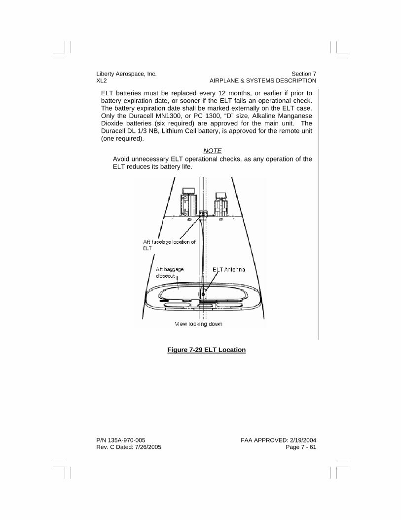
Liberty Aerospace, Inc. Section 7 XL2 AIRPLANE & SYSTEMS DESCRIPTION
P/N 135A-970-005 FAA APPROVED: 2/19/2004 Rev. C Dated: 7/26/2005 Page 7 - 61
ELT batteries must be replaced every 12 months, or earlier if prior to battery expiration date, or sooner if the ELT fails an operational check. The battery expiration date shall be marked externally on the ELT case. Only the Duracell MN1300, or PC 1300, “D” size, Alkaline Manganese Dioxide batteries (six required) are approved for the main unit. The Duracell DL 1/3 NB, Lithium Cell battery, is approved for the remote unit (one required).
NOTE Avoid unnecessary ELT operational checks, as any operation of the ELT reduces its battery life.
Figure 7-29 ELT Location

Section 7 Liberty Aerospace, Inc. AIRPLANE & SYSTEMS DESCRIPTION XL2
FAA APPROVED: 2/19/2004 P/N 135A-970-005 Page 7 - 62 Rev. C Dated: 7/26/2005
ELT OPERATIONAL CHECK (PER FAA ORDER 7310.3s, Chapter 3-3-7)
ELT operation on 121.5 MHz and 243 MHz may be tested for no more than three sweeps of the distress tone and only during the first five min-utes of each hour.
a. Place cushioned support under the fuselage next to the rear access panels.
b. Remove aft baggage compartment closeout to access ELT. c. Disconnect ELT antenna coaxial cable from fitting on ELT unit. d. Turn on BAT/MASTER and AVIONICS MASTER switches. e. Tune COM receiver to 121.5 MHz and ensure receiver audio is
selected to headphones. f. During time period from 00 to 05 minutes past any hour, press
ELT “ON” button. g. Monitor headphones for no more than 3 sweeps of ELT tone. h. Press ELT “RESET” button. Verify that tone ceases and light in
ELT annunciator panel extinguishes. i. Turn off BAT/MASTER and AVIONICS MASTER switches. j. Reconnect ELT antenna coaxial cable k. Replace aft baggage compartment closeout. l. Make required entry in aircraft records.

Liberty Aerospace, Inc. Section 8 XL2 AIRPLANE HANDLING, SERVICE, & MAINTENANCE
P/N 135A-970-005 FAA APPROVED: 2/19/2004 Initial Release Page 8 - 1
SECTION 8
AIRPLANE HANDLING, SERVICE, AND MAINTENANCE
TABLE OF CONTENTS
Introduction ............................................................................ 8 - 3 Identification Plate.................................................................. 8 - 3 Liberty Owner Advisories....................................................... 8 - 3 Publications............................................................................ 8 - 4 Airplane File ........................................................................... 8 - 5 Airplane Inspection Periods ................................................... 8 - 6 Liberty Inspection Programs .................................................. 8 - 6 Preventative Maintenance ..................................................... 8 - 7 Alterations or Repairs ............................................................ 8 - 7 Ground Handling.................................................................... 8 - 8 Towing ............................................................................. 8 - 8 Parking ............................................................................ 8 - 9 Tie-Down ....................................................................... 8 - 10 Jacking................................................................................. 8 - 10 Leveling................................................................................ 8 - 11 Flyable Storage.................................................................... 8 - 12 Servicing .............................................................................. 8 - 13 Oil .................................................................................. 8 - 13 Fuel................................................................................ 8 - 16 Landing Gear................................................................. 8 - 17 Cleaning and Care............................................................... 8 - 17 Windshield and Windows .............................................. 8 - 17 Painted Surfaces ........................................................... 8 - 18 Propeller Care ............................................................... 8 - 18 Engine Care................................................................... 8 - 19 Interior Care................................................................... 8 - 19 Snow and Ice Removal ................................................. 8 - 19

Section 8 Liberty Aerospace, Inc. AIRPLANE HANDLING, SERVICE, & MAINTENANCE XL2
FAA APPROVED: 2/19/2004 P/N 135A-970-005 Page 8 - 2 Initial Release
THIS PAGE INTENTIONALLY LEFT BLANK

Liberty Aerospace, Inc. Section 8 XL2 AIRPLANE HANDLING, SERVICE, & MAINTENANCE
P/N 135A-970-005 FAA APPROVED: 2/19/2004 Initial Release Page 8 - 3
INTRODUCTION This section contains recommended procedures for proper ground han-dling and routine care and servicing of your Liberty XL2. It also identi-fies certain inspection and maintenance requirements that must be fol-lowed to maintain aircraft performance and dependability. A planned schedule of lubrication and preventative maintenance is recommended, based on both required intervals and special climatic or operational con-ditions you may encounter. INDENTIFICATION PLATE Your Liberty XL2 is uniquely identified by information stamped into a metal plate permanently affixed to the left rear fuselage. This informa-tion includes the airplane, serial number, Production Certificate number, Type Certificate number, and date of manufacture. LIBERTY OWNER ADVISORIES Liberty Aerospace, Inc. is committed to continually advising owners and operators of Liberty airplanes to inform them about mandatory and/or recommended aircraft service requirements and product changes. United States Owners
If your airplane is registered in the United States, appropriate Liberty Owner Advisories will be mailed to you automatically according to the most current owner name and address under which the airplane is regis-tered with the FAA. If you wish advisories mailed to an alternate (or ad-ditional) address(es), please contact Liberty Aerospace, by mail or via the internet at www.libertyaircraft.com. International Owners
To receive ongoing Liberty Owner Advisories, please contact Liberty Aerospace, Inc., by mail or via the internet at www.libertyaircraft.com. Subscriptions to Liberty Owner Advisories are normally valid for one year, and can be extended by filling out an Owner Advisory Application or renewal notice.
Section 8 Liberty Aerospace, Inc. AIRPLANE HANDLING, SERVICE, & MAINTENANCE XL2
FAA APPROVED: 2/19/2004 P/N 135A-970-005 Page 8 - 4 Initial Release
PUBLICATIONS Several publications are furnished with the airplane upon initial delivery from the factory. These include:
• This FAA Approved Airplane Flight Manual (AFM) • Liberty Model XL2 Equipment List • Pilot Checklist • Passenger Briefing Card • Liberty Sales and Service Directory
The following additional publications are available from Liberty Aero-space, Inc.:
• Liberty Model XL2 Equipment List (Standard equipment, not refer-enced to an individual airplane).
• A Pilot Information Manual (a duplicate of the AFM, but not kept cur-rent or referenced to an individual airplane).
• An FAA Approved Maintenance Manual. • An Illustrated Parts Catalog
NOTE An Airplane Flight Manual (AFM) which has been lost or destroyed may be replaced by contacting Liberty Aerospace, Inc. Since the AFM is identified for a specific airplane, an affidavit including the owner’s name, airplane serial number, and airplane registration number is required.

Liberty Aerospace, Inc. Section 8 XL2 AIRPLANE HANDLING, SERVICE, & MAINTENANCE
P/N 135A-970-005 FAA APPROVED: 2/19/2004 Initial Release Page 8 - 5
AIRPLANE FILE Miscellaneous data, information, and licenses may be part of the air-plane file. The file should periodically be checked to ensure that all documentation is present and current.
To be displayed (visible) in the airplane at all times: 1. Aircraft Airworthiness Certificate (FAA Form 8100-2 or foreign
equivalent) 2. Aircraft Registration Certificate (FAA Form 8050-3 or foreign equiva-
lent) 3. For flights outside the USA: Aircraft Radio Station License (FCC
Form 556 or foreign equivalent)
To be carried (not necessarily displayed) in the airplane at all times: 1. FAA Approved Airplane Flight Manual (AFM) 2. Current weight and balance information and associated documenta-
tion (including FAA Form 337, if applicable) 3. Equipment List
To be made available upon request: 1. Airplane Logbook 2. Engine Logbook
Most of these items are required by United States Federal Aviation Regulations (FAR). Regulations of other countries may require different or additional data, as well as mandating whether or not certain mainte-nance documentation must be carried in the aircraft or stored in a safe ground location. It is the responsibility of the aircraft operator and/or pilot to ensure compliance with individual requirements.

Section 8 Liberty Aerospace, Inc. AIRPLANE HANDLING, SERVICE, & MAINTENANCE XL2
FAA APPROVED: 2/19/2004 P/N 135A-970-005 Page 8 - 6 Initial Release
AIRPLANE INSPECTION PERIODS All civil aircraft of U.S. Registry must undergo a complete inspection (annual) each twelve calendar months. In addition, aircraft operated commercially (for hire) must have a complete inspection every 100 hours of operation.
The FAA may require additional one-time or recurrent inspections by the issuance of airworthiness directives (ADs) applicable to the airplane, engine, propeller, or other components. It is the responsibility of the owner/operator of the airplane to ensure compliance with all applicable ADs, and, if they are repetitive, take appropriate steps to prevent inad-vertent non-compliance. LIBERTY INSPECTION PROGRAMS In addition to the FAA requirements, Liberty Aerospace requires that propeller mounting bolt torque be checked every 25 operating hours (for wooden or wood/composite propellers only), and requires a somewhat abbreviated inspection of the airplane, engine, and engine components every 50 operating hours.

Liberty Aerospace, Inc. Section 8 XL2 AIRPLANE HANDLING, SERVICE, & MAINTENANCE
P/N 135A-970-005 FAA APPROVED: 2/19/2004 Initial Release Page 8 - 7
PREVENTATIVE MAINTENANCE A certified pilot who owns or operates an airplane not used as an air car-rier is authorized (in the USA) by FAR Part 43, Appendix A, Paragraph C, to perform limited preventative maintenance procedures on the air-plane.
A Liberty XL2 Maintenance Manual must be obtained prior to performing any preventative maintenance, and all such preventative maintenance shall be performed in accordance with the procedures specified in the Maintenance Manual. Refer to FAR Part 43 for a listing of permissible procedures and for logbook entry and other record-keeping require-ments.
NOTE Pilots operating airplanes of other than U.S. Registry should refer to the regulations of the country of certification for information on pre-ventive maintenance that may be performed by the pilot.
ALTERATIONS OR REPAIRS It is essential that both the FAA and Liberty Aerospace, Inc. be con-tacted prior to any alterations to the airplane, or prior to any repairs not covered in detail in the Maintenance Manual, to ensure that the airwor-thiness of the airplane is not compromised or violated.
Alterations or repairs to the airplane must be accomplished by licensed personnel, utilizing only FAA approved components and data, such as the Liberty XL2 Maintenance Manual and/or Liberty Aerospace, Inc. Ser-vice Bulletins.

Section 8 Liberty Aerospace, Inc. AIRPLANE HANDLING, SERVICE, & MAINTENANCE XL2
FAA APPROVED: 2/19/2004 P/N 135A-970-005 Page 8 - 8 Initial Release
GROUND HANDLING TOWING
A tow bar suitable for hand towing and positioning of the airplane is pro-vided as standard equipment and is usually carried in the airplane. A vehicle tow bar is available from Liberty Aerospace. Use of locally fabri-cated vehicle tow bars is discouraged. Towing / Positioning By Hand
a. Attach the tow bar to the nose landing gear b. Remove chocks c. Release parking brake, if necessary d. Move airplane to desired position e. Chock main wheels f. Remove tow bar g. Set parking brake (if necessary, and depending on operator policy)
CAUTION When moving airplane backward, nose landing gear will tend to caster to “hard over” left or right position. Maintain a firm grip on the tow bar to prevent nose landing gear from contacting limit stops at 80-degree left or right position.
To lift the nose wheel of the aircraft manually, use body weight to push down on the vertical stabilizer where the strake meets the fuselage in front of horizontal stabilizer. Do not push on the horizontal stabilizer or rudder. Ensure the underside of fuselage does not touch ground during maneuver. Lower nose wheel gently back to ground, careful not to ‘drop’ the front end during release. Towing / Positioning Using a Tow Vehicle
a. Attach the tow bar to the nose landing gear b. Remove chocks c. Release parking brake if necessary d. Move airplane to desired position e. Chock main wheels f. Remove tow bar from airplane and tow vehicle g. Set parking brake (if necessary, and depending on operator policy)

Liberty Aerospace, Inc. Section 8 XL2 AIRPLANE HANDLING, SERVICE, & MAINTENANCE
P/N 135A-970-005 FAA APPROVED: 2/19/2004 Initial Release Page 8 - 9
CAUTION Due to the risk of damage to the nose landing gear, tow the airplane using a vehicle in the forward direction only. Do not attempt to move the airplane backward using a vehicle. If it becomes necessary to move the airplane backward, disconnect the tow bar from the vehi-cle and move the airplane backward by hand.
PARKING
Short-Term Parking
CAUTION If wheel brakes are hot from prolonged taxi, allow brakes to cool be-fore setting parking brake.
a. Taxi or tow airplane to desired parking position b. Align nose of airplane into the wind c. Ensure nose wheel is centered d. In windy or gusty weather, moor (tie down) airplane e. Set parking brake f. Place chocks in front of and behind main wheels g. Release parking brake h. Secure flight controls in neutral aileron position, retract flaps i. Close and lock doors
NOTE Controls may be secured with ailerons neutral and horizontal stabi-lizers leading edge down by pulling the control stick aft as far as possible and fastening seat belt snugly around it.
Long-Term Parking
In addition to all steps above, perform the following:
a. Tie airplane down (see below) b. Install external rudder gust lock c. Install canopy and pitot covers

Section 8 Liberty Aerospace, Inc. AIRPLANE HANDLING, SERVICE, & MAINTENANCE XL2
FAA APPROVED: 2/19/2004 P/N 135A-970-005 Page 8 - 10 Initial Release
TIE-DOWN
The airplane has three mooring points: one under each wing, and one under the tail. Mooring rings (7/16 x 20 threads) are provided to screw into the mooring points.
a. Park the airplane b. Screw a mooring ring into each of the mooring points c. Attach tie-down ropes (minimum 700 lb tensile strength) to ground
tie-downs and aircraft mooring rings.
NOTE Ensure mooring threads are free of contamination. Screw mooring rings in hand tight only.
JACKING For purposes of changing or servicing a single main landing gear wheel, the airplane may be jacked up on one side only, using a single jack at the applicable main gear jack point. For purposes of changing or servic-ing the nose landing gear wheel, the airplane may either be jacked up using a single jack at the nose wheel jack point, or the tail may be held down and secured using a weighted tail stand attached to the tie-down ring. In either of the two latter cases, the main wheels remain on the ground.
CAUTION The airplane should only be jacked up indoors, in an area free from major air currents.
CAUTION If fewer than all three wheels are to be jacked up, all wheels remain-ing on the ground must be securely chocked.
NOTE The fuselage belly panel must be removed to gain access to the main and nose gear jack points.

Liberty Aerospace, Inc. Section 8 XL2 AIRPLANE HANDLING, SERVICE, & MAINTENANCE
P/N 135A-970-005 FAA APPROVED: 2/19/2004 Initial Release Page 8 - 11
Jacking the Airplane (all three wheels)
a. Remove the fuselage belly fairing to gain access to jack points. b. Place a suitable jack under each main gear jack point. Place a suit-
able jack under the nose gear jack point. c. Operate all three jacks simultaneously to raise airplane from the
ground.
Alternate Method
a. Place a suitable jack under each main gear jack point. b. Secure a weighted tail stand (at least 300 lbs) to the tail tie-down
point. Operate both main gear jacks simultaneously to raise air-plane from the ground.
Lowering the Airplane
a. Ensure area below the airplane is clear b. Lower all jacks simultaneously until all wheels are on the ground. c. Remove all jacks d. Replace fuselage belly fairing
LEVELING To determine lateral level, place a beam level across both cabin doorsills (and at exact right angles to the airplane centerline) with the doors open. Measurement from the forward or aft end of the doorsill may be used to determine that the level has been placed correctly.
To determine longitudinal level, place a beam level lengthwise along either cabin doorsill with the cabin door open.

Section 8 Liberty Aerospace, Inc. AIRPLANE HANDLING, SERVICE, & MAINTENANCE XL2
FAA APPROVED: 2/19/2004 P/N 135A-970-005 Page 8 - 12 Initial Release
FLYABLE STORAGE Airplanes placed in non-operational storage for not more than 30 days, or those that receive only intermittent use during the first 25 hours, are considered to be in flyable storage status.
Every seventh day during flyable storage, the propeller should be ro-tated by hand through five revolutions (ten blades) in its normal direction of operation (CCW as seen from in front of the airplane). This action “loosens” engine oil and maintains the oil film on the cylinder walls help-ing to reduce corrosion.
WARNING Before rotating propeller by hand, confirm that airplane is secured (tied down and/or all three wheels chocked) and that airplane master switch, and FADEC PWR A and B switches are OFF. Treat propel-ler as if it were “live” at all times and do not stand within propeller arc when rotating propeller by hand.
After 30 days, the airplane should be flown for a minimum of 30 minutes, or a ground runup should be made just long enough to bring oil tempera-ture into the lower green arc range. Avoid excessive ground running. Engine runup also helps eliminate accumulations of water or water vapor in fuel lines and other spaces within the engine. Keep fuel tanks full to minimize condensation. Keep batteries fully charged to prevent freezing in cold weather. Refer to the Maintenance Manual for long-term storage.
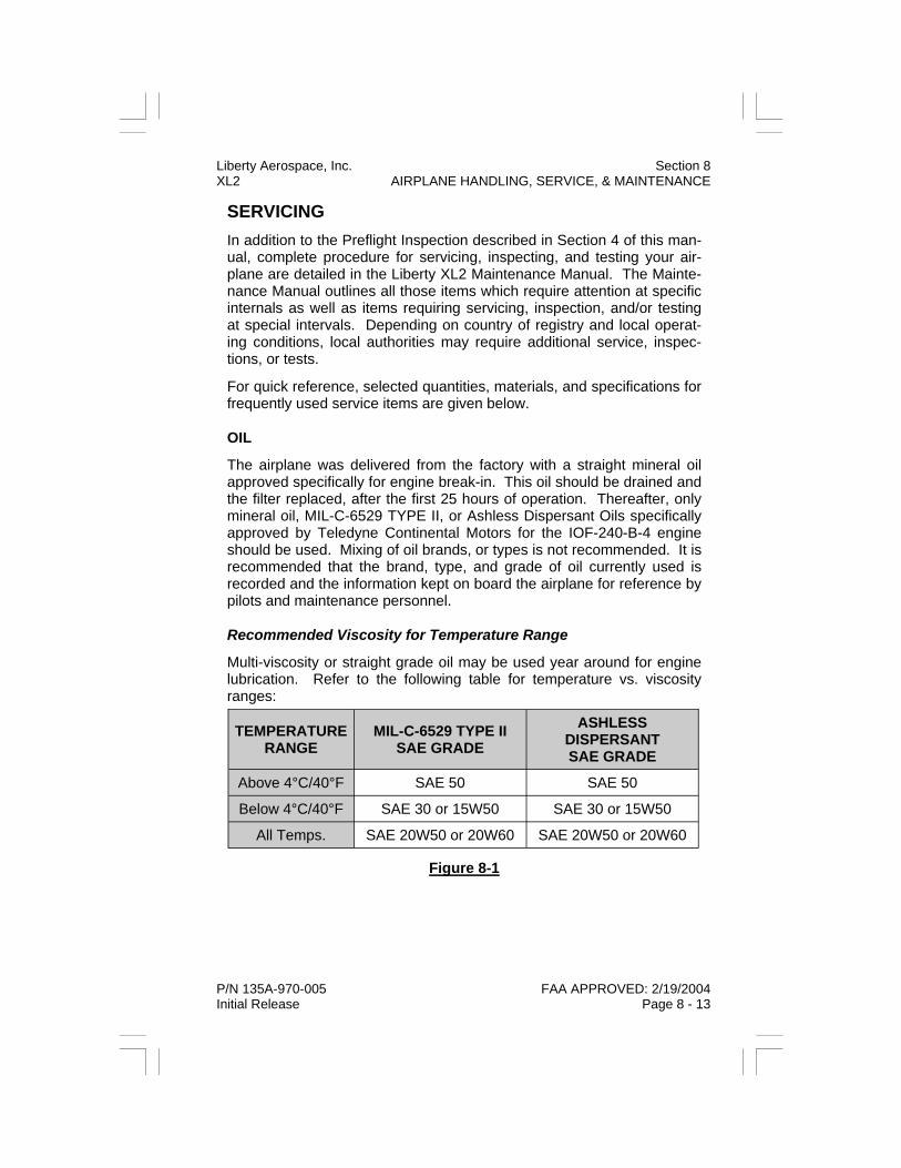
Liberty Aerospace, Inc. Section 8 XL2 AIRPLANE HANDLING, SERVICE, & MAINTENANCE
P/N 135A-970-005 FAA APPROVED: 2/19/2004 Initial Release Page 8 - 13
SERVICING In addition to the Preflight Inspection described in Section 4 of this man-ual, complete procedure for servicing, inspecting, and testing your air-plane are detailed in the Liberty XL2 Maintenance Manual. The Mainte-nance Manual outlines all those items which require attention at specific internals as well as items requiring servicing, inspection, and/or testing at special intervals. Depending on country of registry and local operat-ing conditions, local authorities may require additional service, inspec-tions, or tests.
For quick reference, selected quantities, materials, and specifications for frequently used service items are given below. OIL
The airplane was delivered from the factory with a straight mineral oil approved specifically for engine break-in. This oil should be drained and the filter replaced, after the first 25 hours of operation. Thereafter, only mineral oil, MIL-C-6529 TYPE II, or Ashless Dispersant Oils specifically approved by Teledyne Continental Motors for the IOF-240-B-4 engine should be used. Mixing of oil brands, or types is not recommended. It is recommended that the brand, type, and grade of oil currently used is recorded and the information kept on board the airplane for reference by pilots and maintenance personnel. Recommended Viscosity for Temperature Range
Multi-viscosity or straight grade oil may be used year around for engine lubrication. Refer to the following table for temperature vs. viscosity ranges:
Figure 8-1
TEMPERATURE RANGE
MIL-C-6529 TYPE II SAE GRADE
ASHLESS DISPERSANT SAE GRADE
Above 4°C/40°F SAE 50 SAE 50
Below 4°C/40°F SAE 30 or 15W50 SAE 30 or 15W50
All Temps. SAE 20W50 or 20W60 SAE 20W50 or 20W60
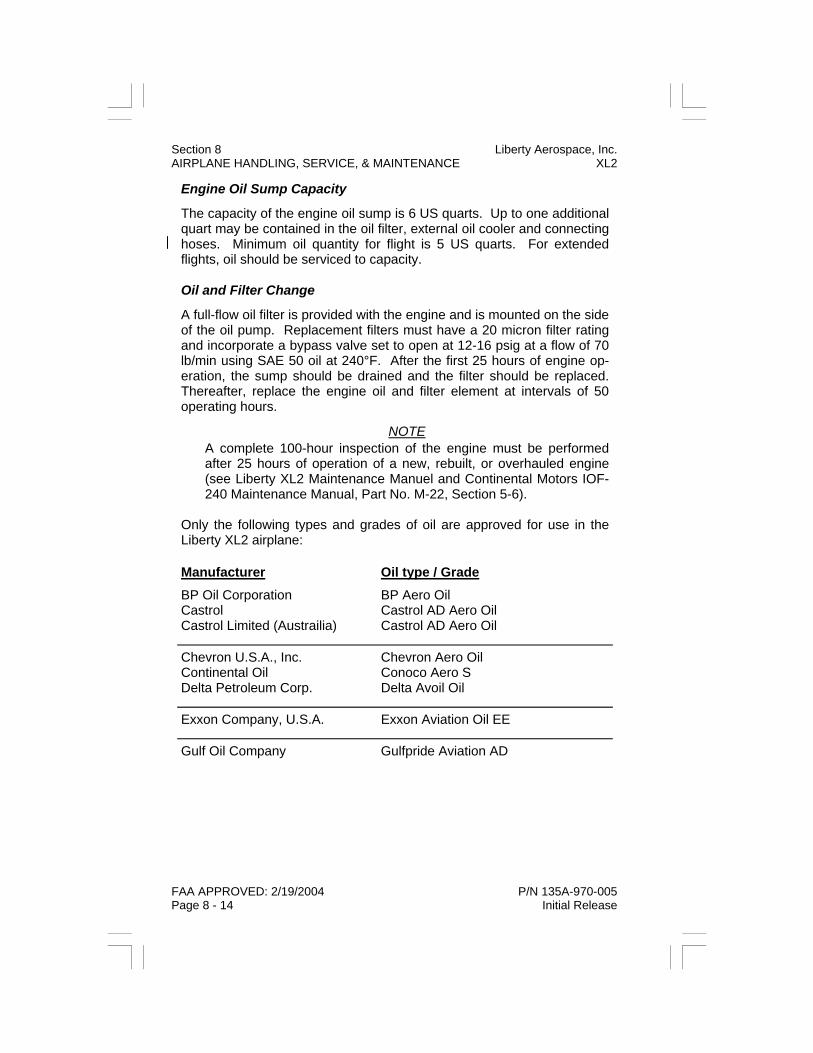
Section 8 Liberty Aerospace, Inc. AIRPLANE HANDLING, SERVICE, & MAINTENANCE XL2
FAA APPROVED: 2/19/2004 P/N 135A-970-005 Page 8 - 14 Initial Release
Engine Oil Sump Capacity
The capacity of the engine oil sump is 6 US quarts. Up to one additional quart may be contained in the oil filter, external oil cooler and connecting hoses. Minimum oil quantity for flight is 5 US quarts. For extended flights, oil should be serviced to capacity. Oil and Filter Change
A full-flow oil filter is provided with the engine and is mounted on the side of the oil pump. Replacement filters must have a 20 micron filter rating and incorporate a bypass valve set to open at 12-16 psig at a flow of 70 lb/min using SAE 50 oil at 240°F. After the first 25 hours of engine op-eration, the sump should be drained and the filter should be replaced. Thereafter, replace the engine oil and filter element at intervals of 50 operating hours.
NOTE A complete 100-hour inspection of the engine must be performed after 25 hours of operation of a new, rebuilt, or overhauled engine (see Liberty XL2 Maintenance Manuel and Continental Motors IOF-240 Maintenance Manual, Part No. M-22, Section 5-6).
Only the following types and grades of oil are approved for use in the Liberty XL2 airplane:
Manufacturer Oil type / Grade BP Oil Corporation Castrol Castrol Limited (Austrailia)
BP Aero Oil Castrol AD Aero Oil Castrol AD Aero Oil
Chevron U.S.A., Inc. Continental Oil Delta Petroleum Corp.
Chevron Aero Oil Conoco Aero S Delta Avoil Oil
Exxon Company, U.S.A. Exxon Aviation Oil EE
Gulf Oil Company Gulfpride Aviation AD

Liberty Aerospace, Inc. Section 8 XL2 AIRPLANE HANDLING, SERVICE, & MAINTENANCE
P/N 135A-970-005 FAA APPROVED: 2/19/2004 Initial Release Page 8 - 15
Manufacturer Oil type / Grade Mobil Oil Company NYCO S.A.
Mobil Aero Oil TURBONYCOIL 3570
Pennzoil Company Pennzoil Aircraft Engine Oil
Phillips Petroleum Company Phillips 66 Aviation Oil, Type A
Phillips 66 X/C Aviation Multi-viscosity Oil, SAE 20W50 or SAE 20W60
Quaker State Oil & Refining Co. Red Ram Limited (Canada)
Quaker State AD Aviation Engine Oil Red Ram X/C Aviation Oil 20W50
Shell Australia Shell Canada Limited
Aeroshell ® W Aeroshell Oil W Aeroshell Oil W 15W50, Anti-wear Formulation Aeroshell Oil W 15W50
Sinclair Oil Company Texaco, Inc. Total France Union Oil Co. of California
Sinclair Avoil Texaco Aircraft Engine Oil Premium AD Total Aero DM 15W50 Union Aircraft Engine Oil HD
Approved Mineral Oil: MIL-C-6529 TYPE II
Section 8 Liberty Aerospace, Inc. AIRPLANE HANDLING, SERVICE, & MAINTENANCE XL2
FAA APPROVED: 2/19/2004 P/N 135A-970-005 Page 8 - 16 Initial Release
FUEL
Approved Fuel Grades (and colors)
100LL Grade Aviation Fuel (Blue)
Fuel Capacity
29.5 US Gallons Total (single tank) (28 US Gallons Usable)
Fuel contamination is most often caused by foreign material present in the fuel system, and may include water, rust, sand, dirt, or microbial or bacterial growth (“bugs” or “sludge”).
Before each flight and/or after each refueling, use a clear sampling con-tainer and drain fuel from both fuel tank sump and the fuel strainer (“gascolator”) drains to determine whether contaminants are present and to verify that the airplane has been serviced with the proper grade (color) of fuel. If the airplane has just been refueled or moved, wait 5 to 10 min-utes to allow heavier contaminants to settle to the bottom of the tank and migrate to the fuel sump (low point).
If any contaminants are observed, continue draining and checking fuel samples until no further contamination is found. It is best to “work down-stream,” i.e., continue draining the fuel tank sump until no further con-tamination is observed, then repeat the procedure at the fuel strainer drain. If necessary, rock or shake the airplane to allow all contaminants to reach the system low points, and then wait 5 to 10 minutes before repeating the draining and sampling procedure. If contamination is still observed, the entire fuel system should be drained and purged by main-tenance personnel.
If misfueling (improper grade or type) is suspected, the entire fuel sys-tem must be drained and purged by maintenance personnel, unless the misfueling can be absolutely and unequivocally ruled out by fueling per-sonnel.
Whenever possible, the fuel tank should be fully serviced after each flight to minimize the air space above the fuel and the attendant possibil-ity of condensation of ambient moisture.

Liberty Aerospace, Inc. Section 8 XL2 AIRPLANE HANDLING, SERVICE, & MAINTENANCE
P/N 135A-970-005 FAA APPROVED: 2/19/2004 Initial Release Page 8 - 17
LANDING GEAR
All three landing gear wheels use 5.00 x 5 tires. All three tires should be inflated to 50 psi.
The dual main wheel brakes utilize a common reservoir in the cockpit center console (aft of the two brake levers). Access to the reservoir is gained by removing the center console upholstery. Service the reservoir with MIL-H-5606A (red) hydraulic fluid. CLEANING AND CARE WINDSHIELD AND WINDOWS
The best cleaner for acrylic transparencies is copious amounts of clear water. The best device for initial removal of dirt, insects, etc., is the palm of a bare (clean) hand. Remove wristwatches, rings, etc. to avoid scratches. Flood the transparency with water while rubbing gently by hand to remove dust, dirt, insects, etc.
If necessary, use a mild soap solution to remove stubborn deposits. Avoid the use of chemical cleaners, as they may lead to crazing of the material.
CAUTION NEVER use any cleaning product containing solvents of any kind. NEVER use any cleaning product containing abrasives of any kind.
Addition of a few drops of mild detergent solution to water used for trans-parency cleaning is permissible to promote “sheeting” and prevent water spots. Either allow transparencies to air-dry, or rub GENTLY with a CLEAN lint-free cloth or chamois.
Section 8 Liberty Aerospace, Inc. AIRPLANE HANDLING, SERVICE, & MAINTENANCE XL2
FAA APPROVED: 2/19/2004 P/N 135A-970-005 Page 8 - 18 Initial Release
PAINTED SURFACES
Painted surfaces can be washed with water and mild soap, then rinsing with water and drying with cloths or chamois. Avoid the use of harsh determent soaps and all abrasives.Stubborn oil and grease stains may be removed using a cloth dampened with Stoddard solvent. Exercise caution to prevent solvent from contacting transparencies (windshield, windows). Avoid rubbing exterior graphics (registration numbers, etc.) with solvent.
The airplane should be waxed regularly with a good automotive wax ap-plied in accordance with the wax manufacturer’s instructions. A heavier coating of wax on leading edges will reduce abrasion.
Ideally, the airplane should be polished by hand after waxing, mechani-cal methods are not recommended. Exercise extreme care when using electric polishers or buffers to avoid overheating the composite fuselage and vertical stabilizer. Use minimum pressure and keep the polisher or buffer moving at all times. PROPELLER CARE
The propeller should be washed and waxed using the same products and procedures as for the painted surfaces of the airplane. Any signifi-cant scratches should be reported to maintenance. Pilots should never attempt to sand out scratches in the propeller.
WARNING The airplane must not be started or flown if any scratches are found that penetrate through the paint and into the wood or composite structure of the propeller.

Liberty Aerospace, Inc. Section 8 XL2 AIRPLANE HANDLING, SERVICE, & MAINTENANCE
P/N 135A-970-005 FAA APPROVED: 2/19/2004 Initial Release Page 8 - 19
ENGINE CARE
The engine may be cleaned with standard cold solvents (Stoddard sol-vent, etc.) using a low-pressure spray only. Ensure that all solvent has evaporated or dried before starting engine.
WARNING Ensure that all engine and accessory breathers and vent openings are sealed (tape, plastic bags, etc.) before cleaning engine. Do not spray sovent directly on or near any electric or electronic (FADEC) accessories or connectors when cleaning engine.
INTERIOR CARE
Floor coverings, carpeted sidewalls, and (fabric) seat covers should be vacuumed at regular intervals. Leather seats may be treated with stan-dard automotive leather upholstery conditioners as necessary.
Instrument panels, cockpit center console, and instrument panel glare shield may be wiped with a dampened soft cloth (water only). Ensure that no solvents or strong cleaning agents are used on interior surface. SNOW AND ICE REMOVAL
If snow has collected on the airplane, it should be removed as soon as possible (ideally, before it has a chance to melt) to prevent melt water from refreezing on the airplane surface or in control surface gaps. Do not use sharp objects or scrapers to remove snow or ice accumulations from airplane. The best method for snow and/or ice removal is to place the airplane in a heated hanger.
CAUTION To avoid melted snow or ice refreezing on or in the aircraft, do not remove aircraft from heated hanger until at least one half hour after all melt water has drained (all dripping has stopped).

Section 8 Liberty Aerospace, Inc. AIRPLANE HANDLING, SERVICE, & MAINTENANCE XL2
FAA APPROVED: 2/19/2004 P/N 135A-970-005 Page 8 - 20 Initial Release
THIS PAGE INTENTIONALLY LEFT BLANK

GARMIN GNS 430 - VHF COMM/NAV/GPS XL-2 Airplane
P/N 135A-970-013 FAA Approved: 7/26/2005 Section 9 Initial Release Page 1 of 10
FAA APPROVED AIRPLANE FLIGHT MANUAL SUPPLEMENT
FOR GARMIN GNS 430 - VHF COMM/NAV/GPS
Serial No:
Registration No:
When installing the Garmin GNS 430 - VHF COMM/NAV/GPS in the Liberty Aerospace XL2, this supplement is applicable and must be inserted in the Supplements Section (Section 9) of the Liberty Aerospace XL2 Airplane Flight Manual. The information contained herein supplements the FAA approved Airplane Flight Manual only in those areas listed herein. For limitations, procedures, and performance information not contained in this document, consult the basic XL2 FAA Approved Airplane Flight Manual.
FAA Approved:
Melvin D Taylor, Manager Atlanta Aircraft Certification Office Federal Aviation Administration

GARMIN GNS 430 - VHF COMM/NAV/GPS
XL-2 Airplane
Section 9 FAA Approved: 7/26/2005 P/N 135A-970-013 Page 2 of 10 Initial Release
PAGE LEFT INTENTIONALLY BLANK

GARMIN GNS 430 - VHF COMM/NAV/GPS XL-2 Airplane
P/N 135A-970-013 FAA Approved: 7/26/2005 Section 9 Initial Release Page 3 of 10
SECTION 1 - GENERAL The GNS 430 System is a fully integrated, panel mounted instrument, which contains a VHF Communications Transceiver, a VOR/ILS receiver, and a Global Positioning System (GPS) Navigation computer. The system consists of a GPS antenna, GPS Receiver, VHF VOR/LOC/GS antenna, VOR/ILS receiver, VHF COMM antenna and a VHF Communications Transceiver. The primary function of the VHF Communication portion of the equipment is to facilitate communication with Air Traffic Control. The primary function of the VOR/ILS Receiver portion of the equipment is to receive and demodulate VOR, Localizer, and Glide Slope signals. The primary function of the GPS portion of the system is to acquire signals from the GPS system satellites, recover orbital data, make range and Doppler measurements, and process this information in real-time to obtain the user’s position, velocity, and time.
Provided the GARMIN GNS 430’s GPS receiver is receiving adequate usable signals, it has been demonstrated capable of and has been shown to meet the accuracy specifications for:
VFR/IFR enroute, terminal, and non-precision instrument approach (GPS, Loran-C, VOR, VOR-DME, TACAN, NDB, NDB-DME, RNAV) operation within the U.S. National Airspace System in accordance with AC 20-138
One of the approved sensors, for a single or dual GNS 530 installation, for North Atlantic Minimum Navigation Performance Specification (MNPS) Airspace in accordance with AC 91-49 and AC 120-33.
The system meets RNP5 airspace (BRNAV) requirements of AC 90-96 and in accordance with AC 20-138, and JAA ACJ 20X4, provided it is receiving usable navigation information from the GPS receiver.
The equipment as installed has been found to comply with the requirements for GPS primary means of navigation in oceanic and remote airspace, when used in conjunction with the 400 Series Trainer Program incorporating the FDE Prediction Program. This does not constitute an operational approval.
Navigation is accomplished using the WGS-84 (NAD-83) coordinate reference datum. Navigation data is based upon use of only the Global Positioning System (GPS) operated by the United States of America.

GARMIN GNS 430 - VHF COMM/NAV/GPS
XL-2 Airplane
Section 9 FAA Approved: 7/26/2005 P/N 135A-970-013 Page 4 of 10 Initial Release
SECTION 2 - LIMITATIONS The GARMIN 430 Pilot’s Guide, P/N 190-00140-00, Rev. A, dated October, 1998 or later appropriate revision must be immediately available to the flight crew whenever navigation is predicated on the use of the system. In addition to the Pilot’s Guide, the appropriate Pilot’s Guide Addendum (if the information is not already incorporated into the Pilot’s Guide) also must be immediately available to the flight crew if lightning detection or traffic advisory equipment is interfaced to the system or if primary means oceanic/remote navigation is conducted.
The GNS 430 must utilize the following or later FAA approved software versions:
Sub-System Version Function
Main GPS COM VOR/LOC G/S
Initial Approval 2.00 2.00 2.00 1.25 2.00
Traffic/Weather Interface 2.08 2.00 2.00 1.25 2.00
Primary Oceanic/Remote 3.00 3.00 2.00 1.25 2.00
TIS Interface 4.00 2.00 2.00 1.25 2.00
The Main software version is displayed on the GNS 430 self-test page immediately after turn-on for 5 seconds. The remaining system software versions can be verified on the AUX group sub-page 2, “SOFTWARE/DATABASE VER”.
IFR enroute and terminal navigation predicated upon the GNS 430’s GPS Receiver is prohibited unless the pilot verifies the currency of the data base or verifies each selected waypoint for accuracy by reference to current approved data.
Instrument approach navigation predicated upon the GNS 430’s GPS Receiver must be accomplished in accordance with approved instrument approach procedures that are retrieved from the GPS equipment data base. The GPS equipment database must incorporate the current update cycle.
Instrument approaches utilizing the GPS receiver must be conducted in the approach mode and Receiver Autonomous Integrity Monitoring (RAIM) must be available at the Final Approach Fix.

GARMIN GNS 430 - VHF COMM/NAV/GPS XL-2 Airplane
P/N 135A-970-013 FAA Approved: 7/26/2005 Section 9 Initial Release Page 5 of 10
Accomplishment of ILS, LOC, LOC-BC, LDA, SDF, MLS or any other type of approach not approved for GPS overlay with the GNS 430’s GPS receiver is not authorized.
Use of the GNS 430 VOR/ILS receiver to fly approaches not approved for GPS requires VOR/ILS navigation data to be present on the external indicator.
When an alternate airport is required by the applicable operating rules, it must be served by an approach based on other than GPS or Loran-C navigation, the aircraft must have the operational equipment capable of using that navigation aid, and the required navigation aid must be operational.
VNAV information may be utilized for advisory information only. Use of VNAV information for Instrument Approach Procedures does not guarantee Step-Down Fix altitude protection, or arrival at approach minimums in normal position to land.
If not previously defined, the following default settings must be made in the “SETUP 1” menu of the GNS 430 prior to operation (refer to Pilot’s Guide for procedure if necessary):
dis, spd kt (sets navigation units to “nautical miles” and “knots”)
alt, vs.... fpm (sets altitude units to “feet” and “feet per minute”)
map datumWGS 84 (sets map datum to WGS-84, see note below)
posn ......deg-min (sets navigation grid units to decimal minutes)
In some areas outside the United States, datums other than WGS-84 or NAD-83 may be used. If the GNS 430 is authorized for use by the appropriate Airworthiness authority, the required geodetic datum must be set in the GNS 430 prior to its use for navigation

GARMIN GNS 430 - VHF COMM/NAV/GPS
XL-2 Airplane
Section 9 FAA Approved: 7/26/2005 P/N 135A-970-013 Page 6 of 10 Initial Release
SECTION 3 – EMERGENCY PROCEDURES ABNORMAL PROCEDURES
If GARMIN GNS 430 navigation information is not available or invalid, utilize remaining operational navigation equipment as required.
If “RAIM POSITION WARNING” message is displayed the system will flag and no longer provide GPS navigational guidance. The crew should revert to the GNS 430 VOR/ILS receiver or an alternate means of navigation other than the GNS 430’s GPS Receiver.
If “RAIM IS NOT AVAILABLE” message is displayed in the enroute, terminal, or initial approach phase of flight, continue to navigate using the GPS equipment or revert to an alternate means of navigation other than the GNS 430’s GPS receiver appropriate to the route and phase of flight. When continuing to use GPS navigation, position must be verified every 15 minutes using the GNS 430’s VOR/ILS receiver or another IFR-approved navigation system.
If “RAIM IS NOT AVAILABLE” message is displayed while on the final approach segment, GPS navigation will continue for up to 5 minutes with approach CDI sensitivity (0.3 nautical mile). After 5 minutes the system will flag and no longer provide course guidance with approach sensitivity. Missed approach course guidance may still be available with 1 nautical mile CDI sensitivity by executing the missed approach.
In an in-flight emergency, depressing and holding the Comm transfer button for 2 seconds will select the emergency frequency of 121.500 Mhz into the “Active” frequency window.

GARMIN GNS 430 - VHF COMM/NAV/GPS XL-2 Airplane
P/N 135A-970-013 FAA Approved: 7/26/2005 Section 9 Initial Release Page 7 of 10
SECTION 4 – NORMAL PROCEDURES DETAILED OPERATING PROCEDURES
Normal operating procedures are described in the GARMIN GNS 430 Pilot’s Guide, P/N 190-00140-00, Rev. A, dated October 1998 or later appropriate revision. Normal operating procedures for the Traffic Information Service (TIS) interface and the Weather Data Link interface are described in the 400/500 Series Garmin Display Interfaces Pilot’s Guide Addendum, P/N 190-00140-13, Rev. B, or later appropriate revision.
PILOT’S DISPLAY The GNS 430 System data will appear on the Pilot’s CDI/HSI. The source of data is either GPS or VLOC as annunciated on the display above the CDI key.
It is the pilot’s responsibility to assure that published or assigned procedures are correctly complied with. Course guidance is not provided for all possible ARINC 424 leg types. See the GNS 530 Pilot’s Guide for detailed operating procedures regarding navigation capabilities for specific ARINC 424 leg types.
AUTOPILOT / FLIGHT DIRECTOR OPERATION Coupling of the GNS 430 System steering information to the autopilot/flight director can be accomplished by engaging the autopilot/flight director in the NAV or APR mode.
When the autopilot/flight director system is using course information supplied by the GNS 430 System and the course pointer is not automatically driven to the desired track, the course pointer on the HSI must be manually set to the desired track (DTK) indicated by the GNS 430. For detailed autopilot/flight director operational instructions, refer to the FAA Approved Airplane Flight Manual Supplement for the autopilot/flight director.
CROSSFILL OPERATIONS For dual GNC 400 Product Series or GNC 500/GNC 400 Product Series installations, crossfill capabilities exist between the number one and number two Systems. Refer to the GARMIN GNS 430 Pilot’s Guide for detailed crossfill operating instructions.

GARMIN GNS 430 - VHF COMM/NAV/GPS
XL-2 Airplane
Section 9 FAA Approved: 7/26/2005 P/N 135A-970-013 Page 8 of 10 Initial Release
AUTOMATIC LOCALIZER COURSE CAPTURE By default, the GNS 430 automatic localizer course capture feature is enabled. This feature provides a method for system navigation data present on the external indicators to be switched automatically from GPS guidance to localizer / glide slope guidance as the aircraft approaches the localizer course inbound to the final approach fix. If an offset from the final approach course is being flown, it is possible that the automatic switch from GPS course guidance to localizer / glide slope course guidance will not occur. It is the pilot’s responsibility to ensure correct system navigation data is present on the external indicator before continuing a localizer based approach beyond the final approach fix. Refer to the GNS 430 Pilot’s Guide for detailed operating instructions.
DISPLAY OF LIGHTNING STRIKE DATA For installations that interface the BFGoodrich WX-500 Stormscope and the GNS 430, lightning strike data detected by the WX-500 will appear on the GNS 430. For detailed operating instructions regarding the interface of the GNS 430 with the WX-500, refer to the WX-500 Pilot’s Guide and the 400/500 Series Display Interfaces Pilot’s Guide Addendum, P/N 190-00140-10, Rev. D, or later appropriate revision for the WX-500 Stormscope interface.
DISPLAY OF TRAFFIC ADVISORY DATA For installations that interface a Traffic Advisory System (TAS) and the GNS 430, traffic data detected by the TAS will appear on the GNS 430. For detailed operating instructions regarding the interface of the GNS 430 with the TAS, refer to the FAA Approved Airplane Flight Manual Supplement for the TAS, the Pilot’s Guide for the TAS and the 430 Pilot’s Guide Addendum for the TAS interface.
DISPLAY OF TRAFFIC INFORMATION SERVICE DATA TIS surveillance data uplinked by Air Traffic Control (ATC) radar through the GTX 330 Mode S Transponder will appear on the moving map and traffic display pages of the GNS 430. For detailed operating instructions regarding the interface of the GNS 430 with the GTX 330, refer to the 400/500 Series Garmin Display Interfaces Pilot’s Guide Addendum, P/N 190-00140-13, Rev. B, or later appropriate revision for the TIS System interface.

GARMIN GNS 430 - VHF COMM/NAV/GPS XL-2 Airplane
P/N 135A-970-013 FAA Approved: 7/26/2005 Section 9 Initial Release Page 9 of 10
SECTION 5 - PERFORMANCE No change
SECTION 6 – WEIGHT AND BALANCE See current weight and balance data.
SECTION 7 – AIRPLANE AND SYSTEM DESCRIPTION See GNS 430 Pilot’s Guide for a complete description of the GNS 430 system.

GARMIN GNS 430 - VHF COMM/NAV/GPS
XL-2 Airplane
Section 9 FAA Approved: 7/26/2005 P/N 135A-970-013 Page 10 of 10 Initial Release
PAGE LEFT INTENTIONALLY BLANK

CABIN HEAT / DEMIST SYSTEM XL-2 Airplane
P/N 135A-970-015 FAA Approved 11/21/2006 Section 9 Initial Release Page 1 of 4
FAA APPROVED AIRPLANE FLIGHT MANUAL SUPPLEMENT
FOR CABIN HEAT / DEMIST SYSTEM
Serial No:
Registration No:
When installing the Cabin Heat / Demist System in the Liberty Aerospace XL2, this supplement is applicable and must be inserted in the Supplements Section (Section 9) of the Liberty Aerospace XL2 Airplane Flight Manual. The information contained herein supplements the FAA approved Airplane Flight Manual only in those areas listed herein. For limitations, procedures, and performance information not contained in this document, consult the basic XL2 FAA Approved Airplane Flight Manual.
FAA Approved:
For: Melvin Taylor, Manager Atlanta Aircraft Certification Office Federal Aviation Administration
Date:

CABIN HEAT / DEMIST SYSTEM
XL-2 Airplane
Section 9 Approved 11/21/2006 P/N 135A-970-015 Page 2 of 4 Revision A: Dated 12/14/2006
Cabin Heat / Demist System Log of Revisions
Rev. To Pages Description
FAA Approval Signature and
Date
A 2.3
Added log of revisions. Added
new placard to Section 2.
for Melvin D. Taylor Manager, Atlanta Aircraft Certification Office, FAA
Atlanta, GA
Date

CABIN HEAT / DEMIST SYSTEM XL-2 Airplane
P/N 135A-970-015 FAA Approved 11/21/2006 Section 9 Revision A Dated: 12/14/2006 Page 3 of 4
SECTION 1 - GENERAL No change
SECTION 2 - LIMITATIONS PLACARDS
On each side of center console above the heater vents:
SECTION 3 – EMERGENCY PROCEDURES SMOKE AND FUME ELIMINATION
If smoke and/or fumes are detected in the cabin, check the engine instruments for any sign of malfunction. If a fuel leak has occurred, actuation of electrical components may cause a fire. If there is a strong smell of fuel in the cockpit, divert to the nearest suitable landing field. Perform a Forced Landing pattern and shut down the fuel supply to the engine once a safe landing is assured.
1. Cabin Heat .............................................................. OFF 2. Fresh Air Vents .................................................... OPEN 3. Prepare to land as soon as possible.
SECTION 4 – NORMAL PROCEDURES No change
SECTION 5 - PERFORMANCE No change
SECTION 6 – WEIGHT AND BALANCE See current weight and balance data.
CLOSE BOTH CENTER TUNNEL
VENTS TO DEFOG

CABIN HEAT / DEMIST SYSTEM
XL-2 Airplane
Section 9 Approved 11/21/2006 P/N 135A-970-015 Page 4 of 4 Initial Release
SECTION 7 – AIRPLANE AND SYSTEM DESCRIPTION CABIN HEAT / DEMIST
Cabin heating is accomplished by means of a passive system (no thermostatic control) supplying heated air for both heating the cabin and windshield demist. The cabin heat/demist system consists of a heater muff (heat exchanger) around the engine exhaust muffler, a heater control valve, air ducting for distribution, windshield demist vents, adjustable leg vents, and a cable control for turning the entire system “on” and “off.”
Heating is accomplished by directing outside fresh air through the heat exchanger, then through the heater control valve, and then distributing the ’heated’ air through ducting to the occupants and windshield demist vents. The windshield demist system is automatically activated when the cabin heat control knob is pulled. Partial air flow to the windshield demist vents will occur anytime one or both of the adjustable leg vents are open. For full air flow to the windshield demist vents, both adjustable leg vents should be closed. The adjustable leg vents are directionally controllable and are located on the lower sides of center console near the inboard leg of each occupant. Very little air flow is generated during idle ground operations; therefore, cabin temperature (flow rates) will vary with aircraft movement, altitude, and airspeed.
SECTION 8 – HANDLING, SERVICE, AND MAINTENANCE
No change
Related Documents