Proprietary and Confidential Information of F5 Networks F5 Signaling Delivery Controller Overload Control Overview Software Version: 4.0.5 Publication Date: June 2014 Catalog Number: FD-014-405-5 Ver. 2

Welcome message from author
This document is posted to help you gain knowledge. Please leave a comment to let me know what you think about it! Share it to your friends and learn new things together.
Transcript

Proprietary and Confidential Information of F5 Networks
F5 Signaling Delivery Controller Overload Control Overview
Software Version: 4.0.5
Publication Date: June 2014
Catalog Number: FD-014-405-5 Ver. 2
F5 Signaling Delivery Controller
Overload Control
Proprietary and Confidential Information of F5 Networks 2
1 ABOUT THIS DOCUMENT .......................................................................................................................... 4
1.1 DOCUMENT OBJECTIVES ................................................................................................ 4
1.2 CONVENTIONS ............................................................................................................. 4
1.1 GLOSSARY OF TERMS AND ABBREVIATIONS ....................................................................... 4
1.2 DOCUMENT VERSION HISTORY ....................................................................................... 6
2 SDC TRAFFIC FLOWS.................................................................................................................................. 7
2 INCOMING TRAFFIC OVERLOAD CONTROL ................................................................................................ 9
2.1 HOW ARE SDC NODES PROTECTED? ................................................................................ 9
2.2 MESSAGE AND BYTE RATE LIMITS .................................................................................... 9
2.2.1 Defining the FEP Rate Limit ............................................................................................................... 9
2.2.2 Defining the CPFs Rate Limit ............................................................................................................ 10
2.2.3 Defining the Origin Peer Rate Limit ................................................................................................. 11
3 OUTGOING TRAFFIC OVERLOAD CONTROL ............................................................................................. 12
3.1 HOW ARE THE CLIENTS, SERVERS, AND SERVER POOLS PROTECTED? ................................... 12
3.2 LOAD BALANCING POLICIES .......................................................................................... 13
3.3 MESSAGE RATE LIMITS FOR A POOL AND/OR PEER ........................................................... 15
3.3.1 Defining the Peer Rate Limit ............................................................................................................ 15
3.3.2 Defining the Pool Rate Limit ............................................................................................................ 15
3.4 POOL RAMP UP.......................................................................................................... 15
3.5 MONITORING DESTINATION PEER HEALTH ...................................................................... 16
4 MONITORING SYSTEM PERFORMANCE AND OVERLOAD CONTROL ........................................................ 17
4.1 STATISTICS ................................................................................................................. 17
F5 Signaling Delivery Controller
Overload Control
Proprietary and Confidential Information of F5 Networks 3
Legal Notices
Document Name: F5 Signaling Delivery Controller 4.0.5 Overload Control Overview
Catalog Number: FD-014-405-5 Ver.2
Publication Date: June 2014
Copyright
© 2005-2014 F5 Networks, Inc. All rights reserved.
F5 Networks, Inc. (F5) believes the information it furnishes to be accurate and reliable. However, F5
assumes no responsibility for the use of this information, nor any infringement of patents or other
rights of third parties which may result from its use. No license is granted by implication or otherwise
under any patent, copyright, or other intellectual property right of F5 except as specifically described
by applicable user licenses. F5 reserves the right to change specifications at any time without notice.
Trademarks
F5 Networks, F5, F5 (design), OpenBloX, OpenBloX (design), Rosetta Diameter Gateway, Signaling
Delivery Controller and SDC, are trademarks or service marks of F5 Networks, Inc., in the U.S. and
other countries, and may not be used without F5’s express written consent.
All other product and company names herein may be trademarks of their respective owners.
Confidential and Proprietary
The information contained in this document is confidential and proprietary to F5 Networks. The
information in this document may be changed at any time without notice.

F5 Signaling Delivery Controller
Overload Control
Proprietary and Confidential Information of F5 Networks 4
1 About this Document
1.1 Document Objectives
This document provides an overview of the overload control capabilities provided by the SDC.
1.2 Conventions
The style conventions used in this document are detailed in Table 1.
Table 1: Conventions
Convention Use
Times New Roman Regular text
Times New Roman
Bold
Names of menus, commands, buttons, and other elements of the
user interface.
Times New Roman
Italic
Quotes and special terms; the first time they appear
Courier New Language scripts
Notes which offer an additional explanation or a hint on how to
overcome a common problem.
Warnings which indicate potentially damaging User operations
and explain how to avoid them.
An example.
For simplicity, throughout this document, the F5 Signaling Delivery Controller will be
referred to as the SDC.
1.1 Glossary of Terms and Abbreviations

F5 Signaling Delivery Controller
Overload Control
Proprietary and Confidential Information of F5 Networks 5
Table 2: Glossary of Terms and Abbreviations
Term Definition
AAA Authentication, Authorization and Accounting.
Cluster SDC’s group of nodes used to provide translation and connectivity
services.
CPF Control Plane Function
Data Dictionary Defines the format of a protocol’s message and its validation
parameters: structure, number of fields, data format, etc.
DRT Data Transfer Request (GTP concept)
EMS Element Management System
FEP Front End Proxy
Flow Logical combination of user defined rules that define the
transaction procedures’ flow routine.
FQDN Fully Qualified Domain Name.
GTP GPRS Tunneling Protocol
HTTP Hypertext Transfer Protocol
IMSI International Mobile Subscriber Identity
JMS Java Message Service
JNDI Java Naming and Directory Interface
LDAP Lightweight Directory Access Protocol
NGN Next Generation Networking.
NMS Network Management System
Peer Physical or virtual addressable entity. A Client or Server Peer in
the NGN network that provides or consumes AAA services.
Pool A group of Server Peers.

F5 Signaling Delivery Controller
Overload Control
Proprietary and Confidential Information of F5 Networks 6
Term Definition
RADIUS Remote Authentication Dial In User Service
SDC Signaling Delivery Controller
SNMP Simple Network Management Protocol
SS7 Signaling System No. 7
TCP Transmission Control Protocol
TLS Transport Layer Security
UDP User Datagram Protocol
URI Universal Resource Identification.
1.2 Document Version History
Date – Version Change Reference
June 2014 – 2 All content reordered. N/A
F5 Signaling Delivery Controller
Overload Control
Proprietary and Confidential Information of F5 Networks 7
2 SDC Traffic Flows
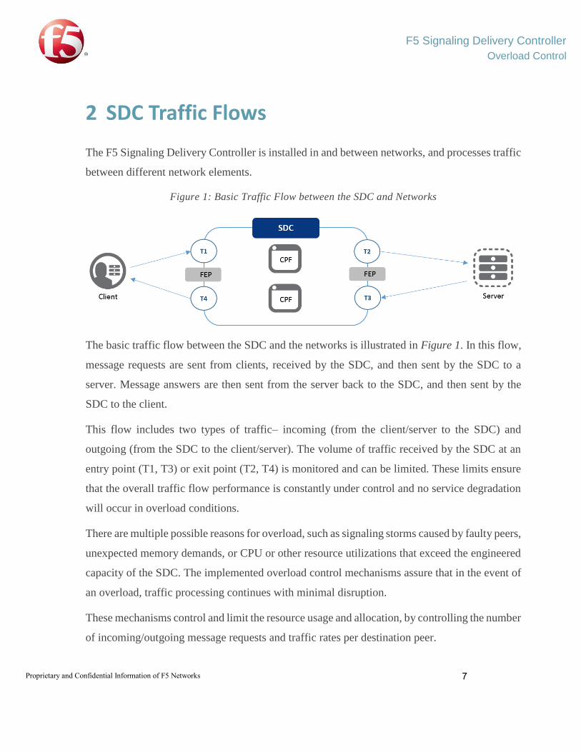
The F5 Signaling Delivery Controller is installed in and between networks, and processes traffic
between different network elements.
Figure 1: Basic Traffic Flow between the SDC and Networks
The basic traffic flow between the SDC and the networks is illustrated in Figure 1. In this flow,
message requests are sent from clients, received by the SDC, and then sent by the SDC to a
server. Message answers are then sent from the server back to the SDC, and then sent by the
SDC to the client.
This flow includes two types of traffic– incoming (from the client/server to the SDC) and
outgoing (from the SDC to the client/server). The volume of traffic received by the SDC at an
entry point (T1, T3) or exit point (T2, T4) is monitored and can be limited. These limits ensure
that the overall traffic flow performance is constantly under control and no service degradation
will occur in overload conditions.
There are multiple possible reasons for overload, such as signaling storms caused by faulty peers,
unexpected memory demands, or CPU or other resource utilizations that exceed the engineered
capacity of the SDC. The implemented overload control mechanisms assure that in the event of
an overload, traffic processing continues with minimal disruption.
These mechanisms control and limit the resource usage and allocation, by controlling the number
of incoming/outgoing message requests and traffic rates per destination peer.

F5 Signaling Delivery Controller
Overload Control
Proprietary and Confidential Information of F5 Networks 8
The overload protection provided for incoming and outgoing traffic (at the SDC entry and exit
point, respectively) is described in the following chapters.

F5 Signaling Delivery Controller
Overload Control
Proprietary and Confidential Information of F5 Networks 9
2 Incoming Traffic Overload Control
2.1 How are SDC Nodes Protected?
Incoming traffic flows are flows in which messages are sent from network elements (client or
server peers) to the SDC. The two SDC entry points that receive this incoming traffic (T1 and
T3) are illustrated in Figure 2. To protect the SDC from receiving excessive traffic, rate limits
can be configured for these points.
Figure 2: Incoming Traffic Received at SDC Entry Points
2.2 Message and Byte Rate Limits
Rate limits are configured to control the amount of traffic that the SDC node receives from either
a client or server peer. These limits are configured by the number of messages and/or bytes that
the SDC can receive. This incoming traffic can either be limited per the client or server peer that
the traffic is sent from, or per the SDC component (FEP/CPF) that receives the traffic.
2.2.1 Defining the FEP Rate Limit
In the incoming traffic flow, the FEP is one of the SDC components that receive traffic from the
client or server peers. Configuring a “receiving rate limit” for a FEP limits the messages that the
FEP is able to receive. This rate limit can be configured by number of messages and/or number
of bytes, and is configured individually for each FEP in a site.

F5 Signaling Delivery Controller
Overload Control
Proprietary and Confidential Information of F5 Networks 10
The FEP receiving rate limit is either configured globally or per peer. When configured globally,
traffic received by the specific FEP – regardless of origin peer – is monitored and compared
against the configured limit.
When configured per peer, traffic received by the specific FEP is monitored per origin peer, and
compared against the configured limit.
Once the FEP receives more traffic than the configured limit, messages that are sent towards it
are not processed and automatically return a busy result code. To avoid excessive busy result
codes, the TCP channel connecting the peers to the specific FEP can also be completely closed
for the remainder of the interval (up to a maximum of one second).
For more information, see the F5 SDC User Guide.
2.2.2 Defining the CPFs Rate Limit
Sometimes, in the incoming traffic flow, the client or server peers are connected directly to the
CPFs, (instead of to a FEP) and send traffic towards them. Configuring a general “receiving rate
limit” for all CPFs applies the defined value to each CPF, and limits the messages that each CPF
is able to receive to the defined value. This rate limit can be configured by number of messages
and/or number of bytes, and is configured per site.
Note: All CPFs are configured with the same rate limit. Unlike the FEP rate limit, unique rate
limits cannot be defined for different CPFs in a site.
The receiving rate limit is either configured globally or per peer. When configured globally,
traffic received by a CPF – regardless of origin peer – is monitored and compared against the
configured limit.
When configured per peer, traffic received by a CPF is monitored per origin peer, and compared
against the configured limit.
Once the CPF receives more traffic than the configured limit, messages that are sent towards it
are not processed and automatically return a busy result code. To avoid excessive busy result
F5 Signaling Delivery Controller
Overload Control
Proprietary and Confidential Information of F5 Networks 11
codes, the TCP channel between the CPF and the client/server peers can also be completely
closed for the remainder of the interval (up to a maximum of one second).
For more information, see the F5 SDC User Guide.
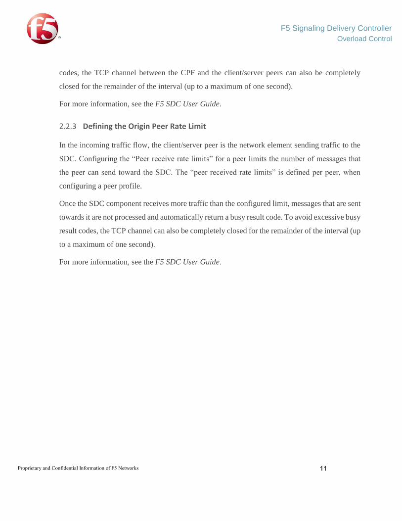
2.2.3 Defining the Origin Peer Rate Limit
In the incoming traffic flow, the client/server peer is the network element sending traffic to the
SDC. Configuring the “Peer receive rate limits” for a peer limits the number of messages that
the peer can send toward the SDC. The “peer received rate limits” is defined per peer, when
configuring a peer profile.
Once the SDC component receives more traffic than the configured limit, messages that are sent
towards it are not processed and automatically return a busy result code. To avoid excessive busy
result codes, the TCP channel can also be completely closed for the remainder of the interval (up
to a maximum of one second).
For more information, see the F5 SDC User Guide.

F5 Signaling Delivery Controller
Overload Control
Proprietary and Confidential Information of F5 Networks 12
3 Outgoing Traffic Overload Control
3.1 How are the Clients, Servers, and Server Pools Protected?
Outgoing traffic flows are flows in which messages are sent from the SDC to network elements
(clients, servers, or pools of servers). The two SDC exit points that send this traffic (T2 and T4)
are illustrated in Figure 3.
Figure 3: Outgoing Traffic Sent from SDC Exit Points
To ensure that the peers and server pools that the SDC sends messages to can efficiently receive
the messages, rate limits can be configured. Load balancing policies can also be defined to
efficiently distribute traffic sent from the SDC between servers in a pool. These policies are used
to deal with and minimize server overload.

F5 Signaling Delivery Controller
Overload Control
Proprietary and Confidential Information of F5 Networks 13
When a peer (or pool of server peers) nears or exceeds the configured rate limits, the traffic sent
to it by the SDC is prioritized and minimized, to ensure that minimal server degradation is
experienced.
The SDC also recognizes that during peer initialization, the peer (or pool of server peers) is not
yet capable of processing traffic to its full ability. Therefore, a peer or pool ramp up period can
be configured, prioritizing the traffic sent and minimizing the volume of traffic sent.
The following sections describe these different mechanisms in detail.
3.2 Load Balancing Policies
Load Balancing policies are used when messages are routed to a pool of server peers. The peer
selection is based on the pool’s defined load balancing policy. The load balancing policies
provided by the SDC are described in Table 3.
Table 3: Load Balancing Policies
Load Balancing Policy Description
Clients Incoming Message
Queue Overload
Indicates that that a Client Remote Peer’s incoming queue utilization has
reached its full capacity
By Precedence Messages are sent to the first peer in the pool, until the channel connecting to
the peer closes. Once the channel closes, messages are sent to the next peer in
the pool, and so on. When the connection channel reopens, messages are again
sent to the first peer.
Round Robin Messages are evenly distributed across the pool’s available peers, in the order
that the peers appear in the pool settings.

F5 Signaling Delivery Controller
Overload Control
Proprietary and Confidential Information of F5 Networks 14
Load Balancing Policy Description
Weighted Round Robin Messages are distributed across the pool’s available server peers according to
a predefined proportion. The weight of each server peer is set during peer
configuration, and should be based upon its ability to handle incoming
requests. Weighted Round Robin is a static algorithm. No external parameters
are taken under account upon request distribution.
With Weighted Round Robin, new requests are distributed in a round robin
pattern, but instead of sending the request to the next available server peer in
line, requests are sent to the server peer that has not yet reached its quota.
Fastest Response Time Messages are sent to the server peers according to the peer’s response time.
The response time is used as the weight of the server peer.
Fastest Response Time is a dynamic algorithm since it takes external
parameters (response time) into account upon request distribution.
Queue Size Ratio Messages are sent to the servers peers according to the weight/queue length
ratio. If Server A’s weight is higher than Server B’s weight, the policy
assumes Server A has a higher traffic handling capacity and maintains a longer
queue of pending requests, compared to other servers in the Pool. That is, the
higher the server’s weight, the greater the number of pending requests it will
handle.
After getting the performance figures from the active peers (RTT or the
number of pending requests), they are normalized between the value 1 and the
maximal ratio (the default value is 100): The highest value is 1 while the
lowest value is the max ratio value.
Queue Size Ratio policy is a dynamic algorithm and responds to external
fluctuations upon request distribution.
Load Based Messages are distributed between servers based on the real-time performance
and load experienced by the servers in the pool. Servers with the least load
will be the first to receive requests.
Contextual The Contextual load balancing policy maps the clients’ session ID’s to a list of
available server peers. This way messages are sent to a specific server peer,
according to their session ID.

F5 Signaling Delivery Controller
Overload Control
Proprietary and Confidential Information of F5 Networks 15
Load Balancing Policy Description
Weighted Contextual The Weighted Contextual load balancing policy maps the clients’ session ID’s
to a list of available server peers. This way messages are sent to a specific
server peer according to their session ID. In addition to the session ID
parameter, traffic distribution is also controlled by a predefined proportion.
The weight of each server peer is set during the peer configuration and should
be based upon its ability to handle incoming requests.
External The peer is selected according to an external script’s rule.
3.3 Message Rate Limits for a Pool and/or Peer
Rate limits are configured to control the number of messages that are sent from an SDC exit
point to either a client peer, server peer, or pool of server peers.
3.3.1 Defining the Peer Rate Limit
For outgoing traffic, the client/server peer is the network element receiving traffic from the SDC.
Configuring a “send rate limit” for a peer limits the number of messages that the peer can receive
from the SDC. The “peer send rate limits” is defined per peer, when configuring a peer profile.
For more information, see the F5 SDC User Guide.
3.3.2 Defining the Pool Rate Limit
For outgoing traffic, the pool of server peers is a collection of server peers receiving traffic from
the SDC. Configuring “Rate Limit (TPS)” for a pool limits the number of messages that the pool
can receive from the SDC. The “Rate Limit (TPS)” is defined per pool, during the pool
configuration. For more information, see the F5 SDC User Guide.
3.4 Pool Ramp Up
The Pool Ramp Up mechanism prevents a specific pool from overloading during startup after
being out of service, busy, or partially out of service. During the ramp up period, which lasts a
minimum of five seconds, traffic is sent to the pool on a gradual basis.

F5 Signaling Delivery Controller
Overload Control
Proprietary and Confidential Information of F5 Networks 16
Pool Ramp Up is defined when configuring a pool. For more information, see the F5 SDC User
Guide.
3.5 Monitoring Destination Peer Health
The SDC monitors the health of the remote peers it communicates with and detects when these
peers are overloaded. This is based on the constant real time monitoring of Diameter traffic error
events, such as:
Timeouts
Response time per peer
Busy answers
Other Diameter error codes
A user-defined Diameter error code
If the rate of the error events exceeds the user configurable threshold, the Diameter peer server
status is changed to “Out of Service” for a defined time interval. When the Remote Peer state is
“Out of Service,” no further requests are delivered to it. Users also have the option to apply an
“Out of Service Partially” status. Peers in this state continue to process existing sessions while
not accepting new sessions. The error event definition and the time interval duration for these
peer states are configured by the user via Groovy script. For more information, see the F5 SDC
User Guide.
F5 Signaling Delivery Controller
Overload Control
Proprietary and Confidential Information of F5 Networks 17
4 Monitoring System Performance and
Overload Control
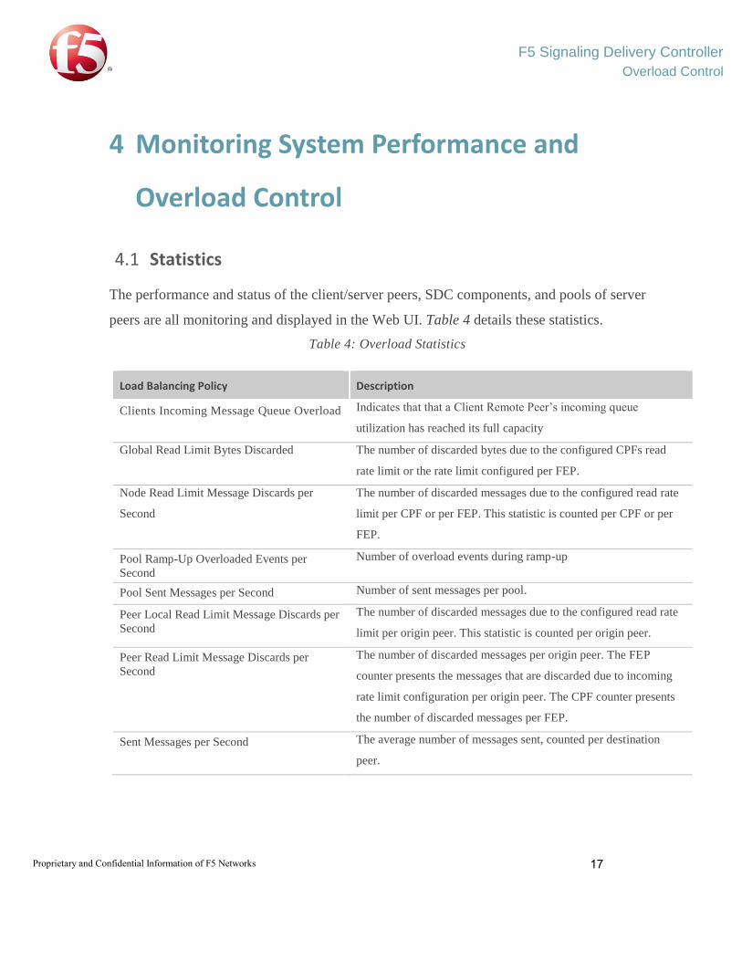
4.1 Statistics
The performance and status of the client/server peers, SDC components, and pools of server
peers are all monitoring and displayed in the Web UI. Table 4 details these statistics.
Table 4: Overload Statistics
Load Balancing Policy Description
Clients Incoming Message Queue Overload Indicates that that a Client Remote Peer’s incoming queue
utilization has reached its full capacity
Global Read Limit Bytes Discarded The number of discarded bytes due to the configured CPFs read
rate limit or the rate limit configured per FEP.
Node Read Limit Message Discards per
Second
The number of discarded messages due to the configured read rate
limit per CPF or per FEP. This statistic is counted per CPF or per
FEP.
Pool Ramp-Up Overloaded Events per
Second
Number of overload events during ramp-up
Pool Sent Messages per Second Number of sent messages per pool.
Peer Local Read Limit Message Discards per
Second
The number of discarded messages due to the configured read rate
limit per origin peer. This statistic is counted per origin peer.
Peer Read Limit Message Discards per
Second
The number of discarded messages per origin peer. The FEP
counter presents the messages that are discarded due to incoming
rate limit configuration per origin peer. The CPF counter presents
the number of discarded messages per FEP.
Sent Messages per Second The average number of messages sent, counted per destination
peer.
F5 Signaling Delivery Controller
Overload Control
Proprietary and Confidential Information of F5 Networks 18
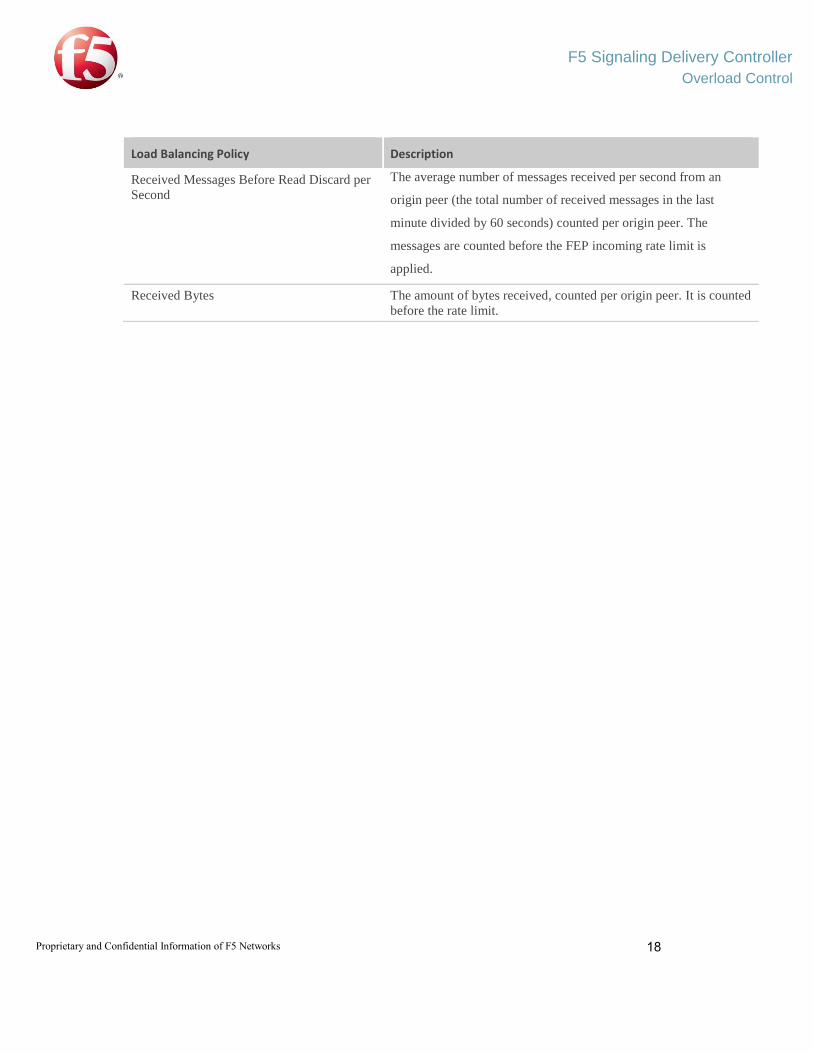
Load Balancing Policy Description
Received Messages Before Read Discard per
Second
The average number of messages received per second from an
origin peer (the total number of received messages in the last
minute divided by 60 seconds) counted per origin peer. The
messages are counted before the FEP incoming rate limit is
applied.
Received Bytes The amount of bytes received, counted per origin peer. It is counted
before the rate limit.
Related Documents