EN Installation Instructions SDI Splitter ICP-SDI-9114

Welcome message from author
This document is posted to help you gain knowledge. Please leave a comment to let me know what you think about it! Share it to your friends and learn new things together.
Transcript
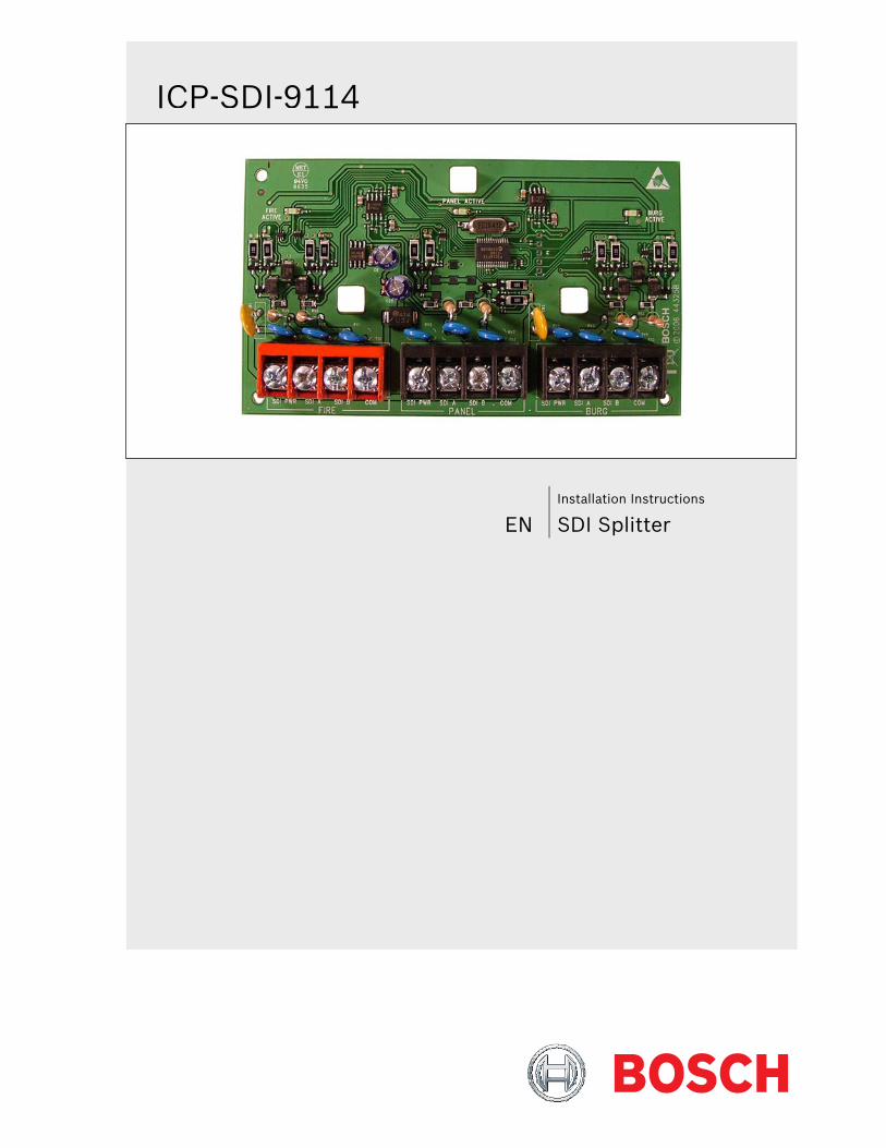
EN Installation Instructions
SDI Splitter
ICP-SDI-9114
ICP-SDI-9114 | Installation Instructions | Listings and Approvals
2 Bosch Security Systems, Inc. | 12/15 | F01U030068-04
Listings and Approvals UL UL 365 Police Station Burglar Alarm Units and Systems UL 609 Local Burglar Alarm Units and Systems UL 864 Control Units for Fire-protective Signaling Systems UL 985 Household Fire Warning System Units UL 1023 Household Burglar Alarm System Units UL 1076 Proprietary Alarm Units UL 1610 Central-station Burglar-alarm Units
ICP-SDI-9114 | Installation Instructions | Contents
.
Bosch Security Systems, Inc. | 12/15 | F01U030068-04 3
Contents 1.0 Introduction ..................... 4 2.0 Mounting ........................ 4 3.0 Installation ...................... 5 4.0 Operation ....................... 8 5.0 Troubleshooting .................. 9 6.0 Specifications ................... 10
Figures Figure 1: Mounting Locations in the Control Panel
Enclosure .................................................. 4 Figure 2: Wiring for One SDI Splitter with Two SDI
Devices on Each Bus ................................. 5 Figure 3: Wiring Configurations for One Splitter
with Two SDI Devices on One Bus and More than Two on the Other Bus ............. 6
Figure 4: Wiring for Two SDI Splitters with Two SDI Device Loads on Two Buses and More than Two on the Other Two Buses ........... 7
Figure 5: SDI Splitter ............................................... 8
Tables Table 1: Troubleshooting ........................................ 9 Table 2: Voltage Values for SDI Splitter Terminals . 9 Table 3: Specifications ......................................... 10
ICP-SDI-9114 | Installation Instructions | 1.0 Introduction
4 Bosch Security Systems, Inc. | 12/15 | F01U030068-04
1.0 Introduction The ICP-SDI-9114 SDI Splitter is an accessory to the B9512G, B8512G, D9412GV4, D7412GV4, D7212GV4, D9412GV3, D7412GV3, D7212GV3, D9412GV2, D7412GV2, D7212GV2, D9412G, D7412G, D7212G, and D9124 control panels. The SDI splitter provides the ability to set up two independent SDI buses from a single SDI connection on the control panel. When this accessory is installed with a control panel and wired to create separate SDI buses for fire and intrusion devices the system is a UL 864 compliant combination control panel.
The ICP-SDI-9114 is not for use with SDI2.
The D7212GV4/D7212GV3/D7212GV2/ D7212G Control Panels are not rated for Commercial Fire.
The SDI splitter has three sets of four-position SDI terminals: PANEL, FIRE, and BURG. The PANEL terminals are used for the SDI connection to the control panel. The terminals labeled FIRE and BURG are handled equally, and either terminal can be assigned to any collection of devices that require two separate buses. The SDI splitter does not affect the operation of the control panel or the associated SDI devices.
2.0 Mounting
UL requires that the SDI splitter be mounted in the same enclosure with the control panel, or in a separate enclosure in the same room within 20 ft (6.1 m) of the control panel and connected by conduit.
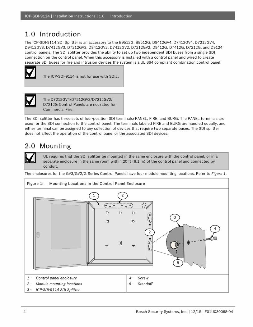
The enclosures for the GV3/GV2/G Series Control Panels have four module mounting locations. Refer to Figure 1.
Figure 1: Mounting Locations in the Control Panel Enclosure
1 - Control panel enclosure 2 - Module mounting locations 3 - ICP-SDI-9114 SDI Splitter
4 - Screw 5 - Standoff
2
24
5
3
1
ICP-SDI-9114 | Installation Instructions | 3.0 Installation
.
Bosch Security Systems, Inc. | 12/15 | F01U030068-04 5
3.0 Installation The SDI splitter operates on power from the control panel, but the DC current is limited to 550 mA for each bus (FIRE and BURG), or enough power for two D1255 or two D1260 keypads. A total of up to 32 SDI devices can connect to the output buses. A fault to the power or data connections of one bus does not affect the other bus.
An external power supply, connected with a common ground, is required to provide power for devices that exceed the 550 mA limit. Refer to Figure 3 and Figure 4 for wiring when an external power supply is used. To determine the current usage for SDI devices, use the Current Rating Chart for Standby Battery Calculations in the B9512G/B8512G Installation and System Reference Guide (P/N:F01U303996), D9412GV4/D7412GV4 Installation and System Reference Guide (P/N: F01U265457), D9412GV3/D7412GV3 Approved Applications Compliance Guide (P/N: F01U143069) or in the D9412GV2/D7412GV2 Approved Applications Compliance Guide (P/N: F01U003639).
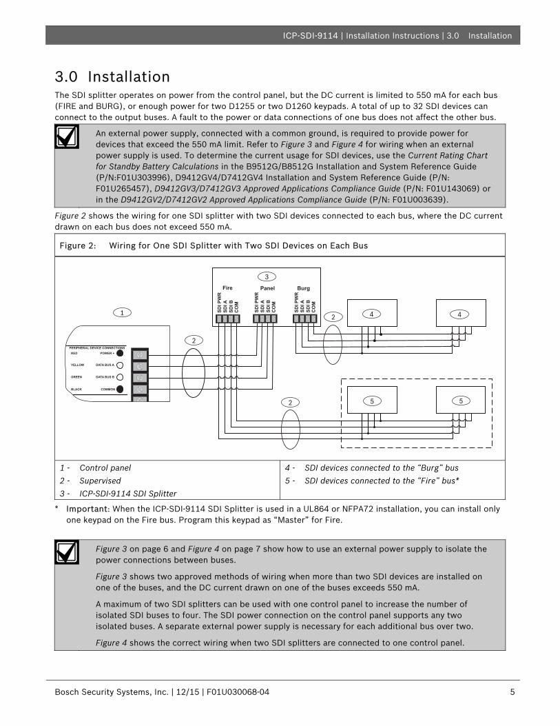
Figure 2 shows the wiring for one SDI splitter with two SDI devices connected to each bus, where the DC current drawn on each bus does not exceed 550 mA.
Figure 2: Wiring for One SDI Splitter with Two SDI Devices on Each Bus
PERIPHERAL DEVICE CONNECTIONSRED POWER +
YELLOW DATA BUS A
GREEN DATA BUS B
BLACK COMMON
BurgFire Panel
SDI P
WR
SDI A
SDI B
CO
M
SDI P
WR
SDI A
SDI B
CO
M
SDI P
WR
SDI A
SDI B
CO
M1
3
4
5
2
2
4
5
2
1 - Control panel 2 - Supervised 3 - ICP-SDI-9114 SDI Splitter
4 - SDI devices connected to the “Burg” bus 5 - SDI devices connected to the “Fire” bus*
* Important: When the ICP-SDI-9114 SDI Splitter is used in a UL864 or NFPA72 installation, you can install only one keypad on the Fire bus. Program this keypad as “Master” for Fire.
Figure 3 on page 6 and Figure 4 on page 7 show how to use an external power supply to isolate the power connections between buses.
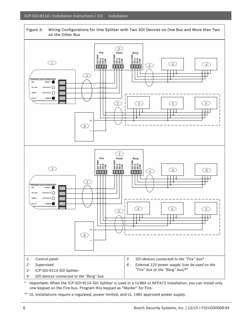
Figure 3 shows two approved methods of wiring when more than two SDI devices are installed on one of the buses, and the DC current drawn on one of the buses exceeds 550 mA.
A maximum of two SDI splitters can be used with one control panel to increase the number of isolated SDI buses to four. The SDI power connection on the control panel supports any two isolated buses. A separate external power supply is necessary for each additional bus over two.
Figure 4 shows the correct wiring when two SDI splitters are connected to one control panel.
ICP-SDI-9114 | Installation Instructions | 3.0 Installation
6 Bosch Security Systems, Inc. | 12/15 | F01U030068-04
Figure 3: Wiring Configurations for One Splitter with Two SDI Devices on One Bus and More than Two on the Other Bus
1
2
2
2
3
PERIPHERAL DEVICE CONNECTIONSRED POWER +
YELLOW DATA BUS A
GREEN DATA BUS B
BLACK COMMON
+
4 4
6
5 5 5
BurgFire Panel
SDI P
WR
SDI A
SDI B
CO
M
SDI P
WR
SDI A
SDI B
CO
M
SDI P
WR
SDI A
SDI B
CO
M
PERIPHERAL DEVICE CONNECTIONSRED POWER +
YELLOW DATA BUS A
GREEN DATA BUS B
BLACK COMMON
+
1
3
4
6
5
4
5 52
2
2
BurgFire Panel
SDI P
WR
SDI A
SDI B
CO
M
SDI P
WR
SDI A
SDI B
CO
M
SDI P
WR
SDI A
SDI B
CO
M
1 - Control panel 2 - Supervised 3 - ICP-SDI-9114 SDI Splitter 4 - SDI devices connected to the “Burg“ bus
5 SDI devices connected to the “Fire” bus* 6 - External 12V power supply (can be used on the
“Fire” bus or the “Burg” bus)**
* Important: When the ICP-SDI-9114 SDI Splitter is used in a UL864 or NFPA72 installation, you can install only one keypad on the Fire bus. Program this keypad as “Master” for Fire.
** UL installations require a regulated, power limited, and UL 1481 approved power supply.
ICP-SDI-9114 | Installation Instructions | 3.0 Installation
.
Bosch Security Systems, Inc. | 12/15 | F01U030068-04 7
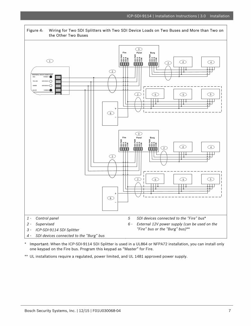
Figure 4: Wiring for Two SDI Splitters with Two SDI Device Loads on Two Buses and More than Two on the Other Two Buses
1
2
2
2
3
PERIPHERAL DEVICE CONNECTIONSRED POWER +
YELLOW DATA BUS A
GREEN DATA BUS B
BLACK COMMON
+
4 4
6
5 5 5
2
2
2
3
+
4 4
6
5 5 5
BurgFire Panel
SDI P
WR
SDI A
SDI B
CO
M
SDI P
WR
SDI A
SDI B
CO
M
SDI P
WR
SDI A
SDI B
CO
M
BurgFire Panel
SDI P
WR
SDI A
SDI B
CO
M
SDI P
WR
SDI A
SDI B
CO
M
SDI P
WR
SDI A
SDI B
CO
M
1 - Control panel 2 - Supervised 3 - ICP-SDI-9114 SDI Splitter 4 - SDI devices connected to the “Burg“ bus
5 SDI devices connected to the “Fire” bus* 6 - External 12V power supply (can be used on the
“Fire” bus or the “Burg” bus)**
* Important: When the ICP-SDI-9114 SDI Splitter is used in a UL864 or NFPA72 installation, you can install only one keypad on the Fire bus. Program this keypad as “Master” for Fire.
** UL installations require a regulated, power limited, and UL 1481 approved power supply.
ICP-SDI-9114 | Installation Instructions | 4.0 Operation
8 Bosch Security Systems, Inc. | 12/15 | F01U030068-04
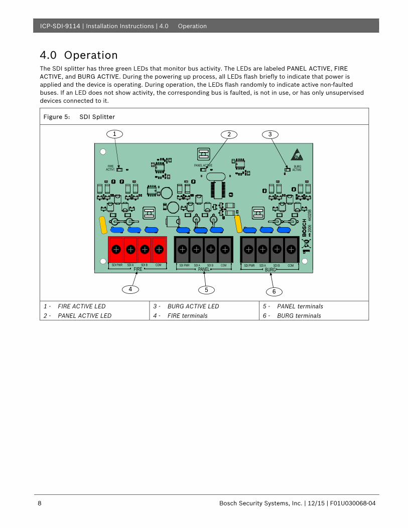
4.0 Operation The SDI splitter has three green LEDs that monitor bus activity. The LEDs are labeled PANEL ACTIVE, FIRE ACTIVE, and BURG ACTIVE. During the powering up process, all LEDs flash briefly to indicate that power is applied and the device is operating. During operation, the LEDs flash randomly to indicate active non-faulted buses. If an LED does not show activity, the corresponding bus is faulted, is not in use, or has only unsupervised devices connected to it.
Figure 5: SDI Splitter
1 32
54 6
PANEL ACTIVE
FIRESDI PWR SDI A SDI B COM
PANELSDI PWR SDI A SDI B COM
BURGSDI PWR SDI A SDI B COM
FIREACTIVE ACTIVE
BURG
1 - FIRE ACTIVE LED 2 - PANEL ACTIVE LED
3 - BURG ACTIVE LED 4 - FIRE terminals
5 - PANEL terminals 6 - BURG terminals
ICP-SDI-9114 | Installation Instructions | 5.0 Troubleshooting
.
Bosch Security Systems, Inc. | 12/15 | F01U030068-04 9
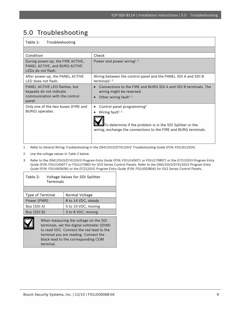
5.0 Troubleshooting Table 1: Troubleshooting
Condition Check During power-up, the FIRE ACTIVE, PANEL ACTIVE, and BURG ACTIVE LEDs do not flash.
Power and power wiring1, 2
After power-up, the PANEL ACTIVE LED does not flash.
Wiring between the control panel and the PANEL SDI A and SDI B terminals1, 2
PANEL ACTIVE LED flashes, but keypads do not indicate communication with the control panel.
• Connections to the FIRE and BURG SDI A and SDI B terminals. The wiring might be reversed.
• Other wiring fault1, 2
Only one of the two buses (FIRE and BURG) operates.
• Control panel programming3 • Wiring fault1, 2
To determine if the problem is in the SDI Splitter or the wiring, exchange the connections to the FIRE and BURG terminals.
1 Refer to General Wiring Troubleshooting in the D9412GV2/D7412GV2 Troubleshooting Guide (P/N: F01U011024).
2 Use the voltage values in Table 2 below.
3 Refer to the D9412GV3/D7412GV3 Program Entry Guide (P/N: F01U143071 or F01U170807) or the D7212GV3 Program Entry Guide (P/N: F01U143077 or F01U17080) for GV3 Series Control Panels. Refer to the D9412GV2/D7412GV2 Program Entry Guide (P/N: F01U003636) or the D7212GV2 Program Entry Guide (P/N: F01U003804) for GV2 Series Control Panels.
Table 2: Voltage Values for SDI Splitter Terminals
Type of Terminal Normal Voltage Power (PWR) 8 to 14 VDC, steady Bus (SDI A) 5 to 10 VDC, moving Bus (SDI B) 3 to 8 VDC, moving
When measuring the voltage on the SDI terminals, set the digital voltmeter (DVM) to read VDC. Connect the red lead to the terminal you are reading. Connect the black lead to the corresponding COM terminal.
ICP-SDI-9114 | Installation Instructions | 6.0 Specifications
10 Bosch Security Systems, Inc. | 12/15 | F01U030068-04
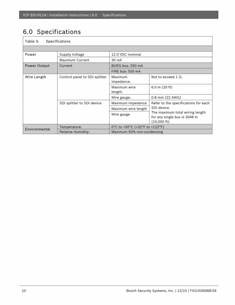
6.0 Specifications Table 3: Specifications
Power Supply Voltage 12.0 VDC nominal
Maximum Current 30 mA Power Output Current BURG bus: 550 mA
FIRE bus: 550 mA Wire Length Control panel to SDI splitter Maximum
impedance: Not to exceed 1 Ω.
Maximum wire length:
6.0 m (20 ft)
Wire gauge: 0.8 mm (22 AWG) SDI splitter to SDI device Maximum impedance Refer to the specifications for each
SDI device. The maximum total wiring length for any single bus is 3048 m (10,000 ft).
Maximum wire length Wire gauge
Environmental Temperature: 0°C to +50°C (+32°F to +122°F) Relative Humidity: Maximum 93% non-condensing
ICP-SDI-9114 | Installation Instructions | Notes .
Bosch Security Systems, Inc. | 12/15 | F01U030068-04 11
Notes
Bosch Security Systems, Inc. 130 Perinton Parkway Fairport, NY 14450-9199 www.boschsecurity.com
© 2015 Bosch Security Systems, Inc. F01U030068-04
Related Documents
![[SHIMADZU] 島津製作所 · cc-ms cv-aas, cv-afs, icp-oes, icp-ms, aas pbb/pbde cr(vl) pb/cd icp-oes. icp-ms icp-oes. icp-ms, icp-oes, icp-ms, cc-ms aas cv-aas aas : aas . - icp-oes](https://static.cupdf.com/doc/110x72/602bef1d6551697710154f3f/shimadzu-eoe-cc-ms-cv-aas-cv-afs-icp-oes-icp-ms-aas-pbbpbde-crvl.jpg)