EyeLink 1000 Installation Guide Tower, Desktop, LCD Arm, Primate, and Long Range Mounts Remote, 2000 Hz and Fiber Optic Camera Upgrades Version 1.5.2 Copyright 2005-2010, SR Research Ltd. EyeLink is a registered trademark of SR Research Ltd., Mississauga, Ontario, Canada

Welcome message from author
This document is posted to help you gain knowledge. Please leave a comment to let me know what you think about it! Share it to your friends and learn new things together.
Transcript
EyeLink 1000 Installation Guide
Tower, Desktop, LCD Arm, Primate,and Long Range Mounts
Remote, 2000 Hz and Fiber OpticCamera Upgrades
Version 1.5.2
Copyright 2005-2010, SR Research Ltd.
EyeLink is a registered trademark of SR Research Ltd.,
Mississauga, Ontario, Canada

ii 2005-2010 SR Research Ltd.
Read instructions before use.
US
C
Certified
Entela Safety Mark: Compliance of this productwith UL 60950 3rd Edition, CSA C22.2 No60950-00-CAN/CSA is certified by Entela, anindependent testing body.
CLASS 1 LED DEVICE
IEC 60825-1 (Ed. 1.2:2001)
CONTACT ADDRESS
SR Research Ltd.150-A1 Terence Matthews CrescentOttawa, Ontario, Canada K2M 1X4Fax: 613-482-4866Phone: 613-271-8686Toll Free: 1-866-821-0731
Email: [email protected]: http://www.sr-research.com/Support: http://www.sr-support.com/
2005-2010 SR Research Ltd.
iii
Table of Contents
1. Introduction..................................................................................................... 1
1.1 Suggested Equipment Layout ............................................................2
2. Installation and System Cabling ................................................................. 4
2.1 Unpacking ........................................................................................4
2.2 Display PC Hardware Installation ......................................................4
2.3 Setting up the Host PC......................................................................5
2.3.1 Rebuilding the Host PC ............................................................................. 5
2.4 Host PC Wiring .................................................................................6
2.4.1 Standard Camera System Installation .................................................... 7
2.4.2 Fiber Optic Camera System Installation ................................................ 10
2.4.3 The Fiber Optic Camera Adapter............................................................ 12
2.4.4 EyeLink Response Device Installation ................................................... 13
2.4.5 Analog Card Installation ......................................................................... 14
2.4.6 Camera Lens Selection............................................................................ 15
3. Tower Mount Installation ........................................................................... 16
3.1 Mounting the Tower to a Table.........................................................17
3.2 Mounting the High-speed Camera and Cabling.................................18
3.2.1 Cabling for the Standard Camera .......................................................... 19
3.2.2 Cabling for the Fiber Optic Camera........................................................ 19
3.3 Adjusting Head Rest Components....................................................20
4. Desktop Mount / EyeLink Remote Installation..................................... 21
4.1 Mounting the EyeLink 1000 High-Speed Camera and Cabling...........21
4.1.1 Cabling for the Standard Camera .......................................................... 23
4.1.2 Cabling for the Fiber Optic Camera........................................................ 23
4.2 Adjusting the Desktop Mount (Monocular, Binocular and Remote Recording)24
4.3 EyeLink Remote Hardware Adjustment for the Desktop Mount .........25
5. LCD Arm Mount Installation ...................................................................... 26
5.1 Choosing a Table.............................................................................26
5.2 Affixing the Arm Base to a Tabletop .................................................28
5.3 Assembling the LCD Arm Components.............................................29
5.4 Mounting the EyeLink 1000 High-Speed Camera..............................30
5.5 Attaching the Cables .......................................................................31

iv 2005-2009 SR Research Ltd.
5.6 Adjusting the Tension Points on the LCD Arm..................................33
5.7 LCD Arm Mount Adjustments for Monocular and Remote Recording .33
5.8 Disassembling and Transporting the LCD Arm Mount ......................34
5.8.1 Option 1: Remove LCD Arm and Camera Assembly as a Unit ............ 35
5.8.2 Option 2: Remove Camera Assembly then Remove the LCD Arm ....... 35
6. Primate Mount Installation ........................................................................ 36
6.1 Primate Mount Hardware Considerations.........................................37
7. Long Range Mount Installation ................................................................. 40
7.1 Description of the Components........................................................40
7.2 Overview of Setting the Mount .........................................................41
7.3 Securing the EyeLink 1000 Fiber Optic Camera Head.......................42
7.4 Securing the Illuminator..................................................................43
7.5 Affixing the Mounting Bar................................................................44
7.6 Cabling for Long Range System........................................................44
7.7 Long Range Camera Setup ..............................................................46
7.7.1 Acquire Preliminary Measurements ....................................................... 46
7.7.2 Assemble the Long Range Mount Components ..................................... 46
7.7.3 Align the Camera Head and Illuminator................................................ 48
7.7.4 Put the Mount into Position and Find the Eye ....................................... 49
7.8 Installation in a MEG Room.............................................................50
7.9 MRI Installation ..............................................................................52
7.9.1 Determine the Mount and Configuration to Use .................................... 53
7.9.2 Mounting the Camera Head and Illuminator......................................... 57
7.9.3 The Head Coil Mirror ............................................................................... 59
7.9.4 Measuring and Using the Eye-to-Camera Distance .............................. 60
7.9.5 Align the Camera Head and Illuminator................................................ 60
7.9.6 Put a Volunteer/Confederate in the Scanner and Find the Eye(s) ...... 60
7.9.7 Adjust Image Thresholds and Focus the Lens ...................................... 61
7.10 Calibration and Drift Correcting with the Long Range System...........62
7.10.1 Calibrating Atypical Spatial Areas ..................................................... 62
7.10.2 Drift Correction..................................................................................... 63
8. Testing the Host PC Installation............................................................... 65
8.1 Running the EyeLink Host Program.................................................65
8.2 Troubleshooting Instructions...........................................................67

2005-2010 SR Research Ltd.
v
8.2.1 SCD file does not exist ............................................................................ 67
8.2.2 “No Hardware” error ............................................................................... 67
8.2.3 EyeLink CL camera not found ................................................................ 67
8.2.4 ERROR: no sync found............................................................................ 67
8.2.5 Error: No Optilink head found. ............................................................... 68
8.3 EyeLink Data Storage......................................................................68
8.4 Customizing Your PHYSICAL.INI Settings.........................................68
8.4.1 Measuring screen_phys_coords ............................................................. 69
8.4.2 Measuring screen_distance .................................................................... 70
8.4.3 Entering Values into PHYSICAL.INI ....................................................... 70
9. Display PC Software Installation............................................................... 72
9.1 Windows Installation.......................................................................72
9.1.1 Installing the EyeLink 1000 Experiment Programming Kit .................. 72
9.1.2 Installing the IO Port Access Driver........................................................ 72
9.1.3 Installing the EyeLink Data Viewer and Experiment Builder Software73
9.1.4 USB License Key Installation ................................................................. 73
9.1.5 Setting up EyeLink 1000 Network Connection...................................... 73
9.1.6 System and Programming Tools Required............................................. 74
9.2 Mac OSX Installation ......................................................................75
10. Appendix A: Host PC Hardware Installation ........................................... 76
10.1 Installing the High-Speed Frame Grabber - PCI card.........................76
10.2 Installing the Ethernet Card ............................................................76
10.3 Installing the Data Translation Analog Card (Optional) .....................77
11. Appendix B: Windows 2000/XP Host PC Software Installation ......... 78
11.1 Install System Commander..............................................................78
11.2 Resize Existing Disk Partition ..........................................................79
11.3 Create the EyeLink 1000 Host Application partition .........................81
11.4 Copy the Host Application files to the New Partition..........................82
11.5 Configuring the Keyboard................................................................83
11.6 Transfer the System to make the EyeLink Partition Bootable ............83
11.7 Organize System Commander’s ‘OS Selection Menu’.........................84
11.8 Automated boot into the EyeLink 1000 Operating System.................85
12. Appendix C: Host PC Software Installation Under Windows Vista .... 86
12.1 Formatting the Hard Drive under ROM-DOS ....................................86
vi 2005-2009 SR Research Ltd.
Figures
Figure 1-1: Suggested EyeLink 1000 System Layout ..................................................... 2
Figure 2-1: The Standard Camera (left) and Fiber Optic Camera Base Box and CameraHead (right).................................................................................................................... 6
Figure 2-2: Host and Display PC Basic Cabling .............................................................. 8
Figure 2-3: Fiber Optic Camera Components................................................................ 10
Figure 2-4: Camera Base Box and Cabling affixed to the side of the Host PC .......... 12
Figure 2-5: The Camera Adapter (left) with Camera Head inserted (right) ................ 13
Figure 2-6: VPixx Button Boxes (left), VPixx Button Box Parallel Port Pin Adapter,modified Gravis Destroyer gamepad, and Microsoft USB Sidewinder gamepad(right)............................................................................................................................ 13
Figure 3-1: Components of EyeLink 1000 Tower .......................................................... 16
Figure 3-2: Clamping Chinrest to Table (right), Placing and Adjusting Tower Mount17
Figure 3-3: Adjust Height of Tower to Half the Screen Area of Monitor ..................... 18
Figure 3-4: Views of the EyeLink 1000 Tower and Camera ......................................... 18
Figure 3-5: Camera and Illuminator Cables for a Standard Camera Used in the TowerMount........................................................................................................................... 19
Figure 3-6: Fiber Optic Camera in the Tower Mount.................................................... 20
Figure 4-1: EyeLink 1000 Desktop Mount Components .............................................. 21
Figure 4-2: Desktop Mount Camera Adjustment .......................................................... 21
Figure 4-3: Camera Level Position for Remote and Stabilized Monocular Recording22
Figure 4-4: Camera Angled Position for Stabilized Binocular and Monocular Recording...................................................................................................................................... 23
Figure 4-5: Camera and Illuminator Cables from Desktop Mount ............................. 23
Figure 4-6: Fiber Optic Camera in the Desktop Mount viewed from the front (left) andrear (right).................................................................................................................... 24
Figure 5-1: Typical EyeLink 1000 LCD Arm Mount Installation ................................. 26
Figure 5-2: EyeLink 1000 LCD Arm Mount Components: LCD Arm Mount Base, Arm,Camera and LCD Assembly....................................................................................... 27
Figure 5-3: Two Configurations of the LCD Arm Mount Base ..................................... 28
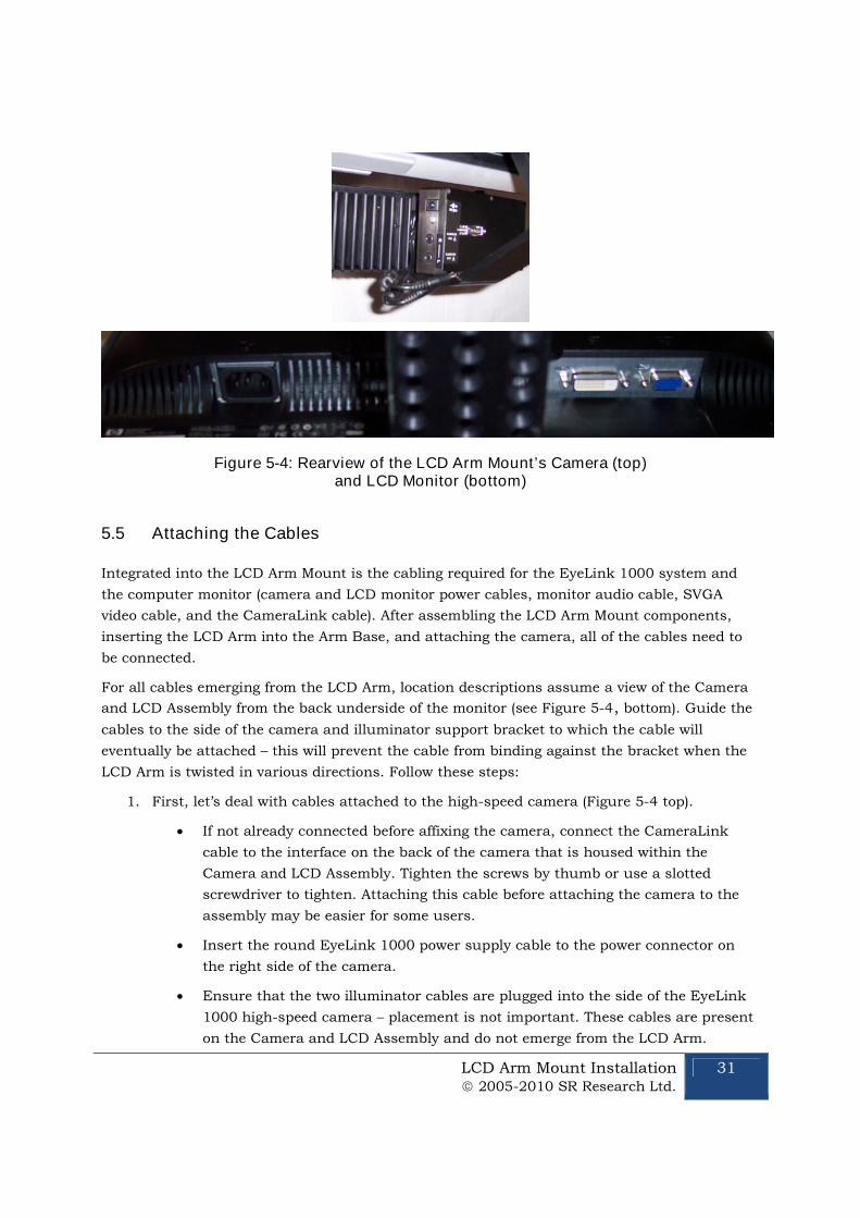
Figure 5-4: Rearview of the LCD Arm Mount’s Camera (top) and LCD Monitor (bottom)...................................................................................................................................... 31
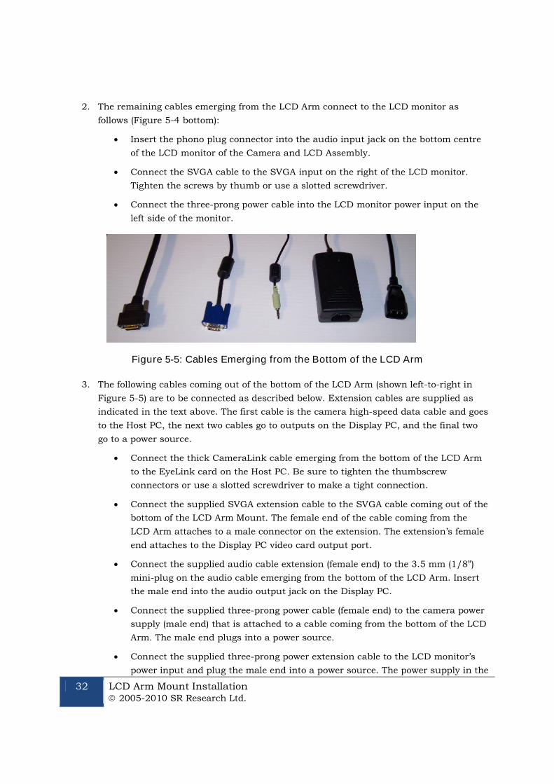
Figure 5-5: Cables Emerging from the Bottom of the LCD Arm .................................. 32
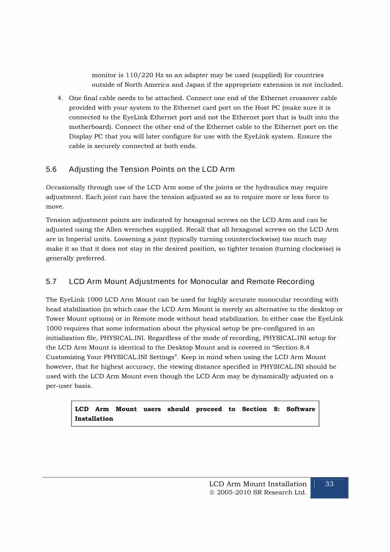
Figure 5-6: Securing the LCD Arm for Disassembling and Transporting .................. 34
Figure 6-1: Typical EyeLink 1000 Primate Mount Installation ................................... 36

2005-2010 SR Research Ltd.
vii
Figure 7-1: EyeLink 1000 Long Range Mount affixed to a Desktop Base (left) andpictured with a variety of lenses and Tripod Adapter (right) ................................. 40
Figure 7-2: Mounting Bar and Clips-note Guide Pins on the Camera Head clip (left)40
Figure 7-3: Fiber Optic Camera Head with lens (left), attached to the Camera HeadBracket (center), Guide Holes in the Camera Head Bracket accept Guide Pins fromCamera Head Clip (right) ........................................................................................... 42
Figure 7-4: Bracket in the Level Position (left) and Angled (right) – without the CameraHead (top) and with the Camera Head (bottom)...................................................... 43
Figure 7-5: Illuminator attached using two brass thumbscrews (left), or singlethumbscrew (center), rotates around the Mounting Bar when its knob is releasedto adjust tilt (right) ..................................................................................................... 43
Figure 7-6: Tripod Adapter (left), Desktop Base (middle) and Mounting Bar attached tothe Tripod Adapter using Two Brass Bolts (right)................................................... 44
Figure 7-7: Male DB-9 connector (left-to-right), gender changer with female connectorshowing, BNC connectors, LEMO connectors, and Battery System..................... 45
Figure 7-8: Focusing the Illuminator.............................................................................. 47
Figure 7-9: Pointing the Camera – a visible illumination boundary indicating poorlighting of the left portion of the camera’s view (left) and a fully illuminated targetindicating intense and uniform illumination (right) ............................................... 49
Figure 7-10: Screen Mount used in conjunction with the Elekta Neuromag screen (left)and a custom-built wood-frame screen (right) ........................................................ 52
Figure 7-11: Tray Mount with optional screen for Siemens family of scanners (left),Screen Mount (middle), and Siemens Allegra short bore mount (right) ............... 53
Figure 7-12: Tray Mount for Siemens family of scanners pictured from above withoptional screen (left), from behind with screen (top-middle) and configured foruser-supplied screen (bottom-middle), riser block on screen (top-right) and fromabove (bottom-right) ................................................................................................... 55
Figure 8-1: Booting into the EyeLink Partition.............................................................. 65
Figure 8-2: Host Application Camera Setup Screen ..................................................... 66
Figure 8-3: Host PC Set Options Screen ........................................................................ 66
Figure 8-4: Measuring screen_phys_cords..................................................................... 69
Figure 10-1: High-Speed Frame Grabber....................................................................... 76
Figure 10-2: D-Link Ethernet Card ................................................................................ 77
Figure 10-3: Analog Card ................................................................................................. 77
Figure 11-1: License Code Entry..................................................................................... 78
Figure 11-2: Enable System Commander ...................................................................... 79
Figure 11-3: Select Partitioning then Manual Partitioning .......................................... 79
Figure 11-4: Partition Selection and Resizing ............................................................... 80
viii 2005-2009 SR Research Ltd.
Figure 11-5: Partition and Partition Type Selection...................................................... 80
Figure 11-6: Create a Custom FAT 32 Partition............................................................ 81
Figure 11-7: Windows Explorer Tools Folder Options… Dialog .................................. 82
Figure 11-8: Select Partition to Rename ........................................................................ 84
Figure 11-9: Select Description and Icons ..................................................................... 85
Figure 11-10: Order Add and Remove ............................................................................ 85
Introduction 2005-2010 SR Research Ltd.
1
1. Introduction
This document provides hardware and software installation instructions for the EyeLink 1000
using the Tower, Desktop, Primate, LCD Arm or Long Range mounts.
There are two EyeLink 1000 cameras (the Standard camera and the Fiber Optic camera) and
each is compatible with all of the different mount types with the exception that only the Fiber
Optic camera works with the Long Range Mount. The cameras have identical technical
specifications, though the Fiber Optic camera has a non-ferromagnetic optimized design to
operate in electromagnetically sensitive environments such as is required for EEG, MEG or
MRI.
Both EyeLink 1000 cameras can be upgraded to enable 2000 Hz recording, or to use the
EyeLink 1000 as a Remote eye tracker that requires no head stabilization. While the 2000 Hz
camera upgrade is compatible with all mount options, the EyeLink Remote upgrade works with
only the Desktop and LCD Arm Mounts.
For the simplicity of presentation, these eye tracker configurations are collectively referred to as
the EyeLink 1000 throughout this document, with important exceptions noted where
necessary.
The basic steps in installing the EyeLink 1000 system are:
1) Unpack and Install the EyeLink 1000 Hardware.
2) If your system did not come with a preconfigured Host PC, install necessary Operating
System and EyeLink 1000 Host Application software on the Host PC you have acquired.
3) Install and configure the EyeLink 1000 Windows Display Software (API and example
experiments) on the Display PC.
4) Test the installation.
If you received a pre-configured Host PC with your eye tracker the installation process should
take under an hour. If you are configuring your own Host PC, the installation process will take
about two hours. Either way, budget this amount of time to dedicate to the process.
If you have questions or encounter a problem during the installation process, please contact
SR Research through one of the contact channels listed in the contacts section of our website
at http://www.sr-research.com
If you would like to ensure that a technical representative is available for direct phone support
during your installation, please contact your SR Research representative to book a time for
installation phone support. Please try to arrange an installation time with at least one week’s
notice.
2 Introduction 2005-2010 SR Research Ltd.
1.1 Suggested Equipment Layout
The layout of the EyeLink 1000 equipment is important if participant setup is to be convenient,
and lighting problems are to be avoided. Before setting up the equipment, check the
arrangement of the room to be used against these suggestions. These will aid in the ease of
acquiring good experimental data.
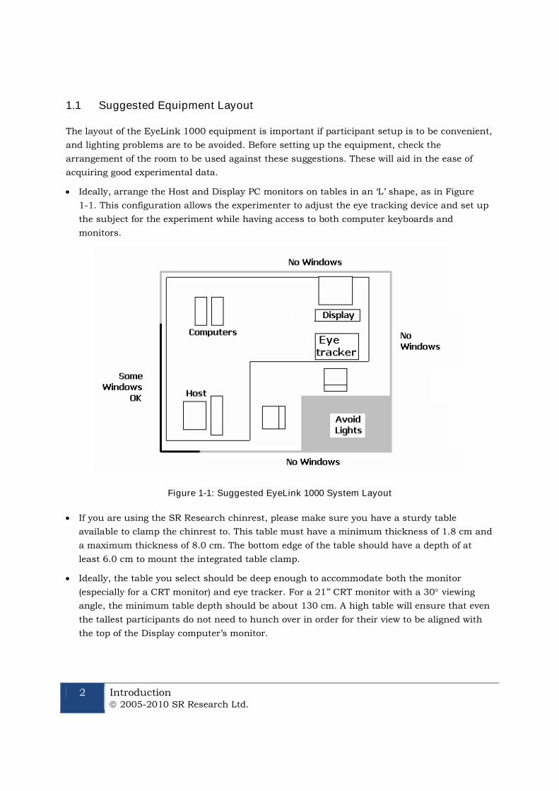
Ideally, arrange the Host and Display PC monitors on tables in an ‘L’ shape, as in Figure
1-1. This configuration allows the experimenter to adjust the eye tracking device and set up
the subject for the experiment while having access to both computer keyboards and
monitors.
Figure 1-1: Suggested EyeLink 1000 System Layout
If you are using the SR Research chinrest, please make sure you have a sturdy table
available to clamp the chinrest to. This table must have a minimum thickness of 1.8 cm and
a maximum thickness of 8.0 cm. The bottom edge of the table should have a depth of at
least 6.0 cm to mount the integrated table clamp.
Ideally, the table you select should be deep enough to accommodate both the monitor
(especially for a CRT monitor) and eye tracker. For a 21’’ CRT monitor with a 30 viewing
angle, the minimum table depth should be about 130 cm. A high table will ensure that even
the tallest participants do not need to hunch over in order for their view to be aligned with
the top of the Display computer’s monitor.
Introduction 2005-2010 SR Research Ltd.
3
Avoid windows or other bright light sources that could cause reflections on the host and
display monitors. The grey walls highlighted in Figure 1-1 are locations where bright light
sources will cause reflections.
Supply sufficient light in the room. The best way to light the room is with ceiling-mounted
fluorescent lights, above and no more than two meters behind the computer monitors.
Painting the walls light colors or white will maximize ambient light as well.
Avoid environmental distractions. Be sure the room can be kept quiet, that no distracting
items are viewable by the participant, and so on. It is a good idea to ensure that the
participant cannot see the host monitor without turning their head (discourage this).
Supply a comfortable, stable chair for the participants. It should not wobble or move when
sat in, and the back should be firmly attached to the seat - springiness encourages some
participants to rock forwards and back. A chair with a concave back also discourages
shifting of the body, as does a high back. The top of the chair back should be just below the
shoulders on an average participant. Finally, make sure participants can enter and leave the
chair easily, as the chair will be close to the table with the Display PC monitor.
4 Installation and System Cabling 2005-2010 SR Research Ltd.
2. Installation and System Cabling
IMPORTANT:
1. Power off computers before connecting or disconnecting any cables!
Ensure that all cabling is properly connected and connectors are properly
secured to the Host PC and the EyeLink 1000 camera before use.
2. Ensure that the RED switch on the back of the Host PC power supply
(near the on/off switch) matches your country’s voltage! (e.g.,115 or 230 V)
3. Static Electricity Discharge may cause permanent damage to your system.
In order to avoid possible static electricity discharge during installation,
please discharge any static electricity accumulated in your body by touching
a grounded metal surface or the computer case for a few seconds.
2.1 Unpacking
Unpack all of the items you have received from SR Research Ltd. If the system has been stored
or transported at a temperature below 10°C, allow all parts to warm to room temperature
before proceeding.
If you are unpacking the EyeLink 1000 Tower Mount, please be careful as it contains glass that
may have been broken during shipping.
IMPORTANT: The EyeLink 1000 Tower assembly should be held by the
vertical posts and should NEVER be held by the mirror or the
components attached to the mirror.
2.2 Display PC Hardware Installation
Set up the Display PC (the computer to be used to deliver the experiment to the subject and to
control EyeLink 1000 calibration) at the desired location (see Section and Figure 1-1 for a
suggested layout). This includes connecting the keyboard and mouse to the computer, as well
as the power supply and monitor cables.
The requirements for the Display PC depend greatly on the type of experimental paradigms for
which the EyeLink 1000 will be used. For example, gaze contingent paradigms generally
require more computing power than simple cognitive paradigms because the computer display
needs to be updated as quickly as possible. Similarly, video and audio intensive experiments
may need faster hard disks to support the transfer of large video file data to the computer in a
timely manner. The following requirements are suggestions for a Display PC configuration that

Installation and System Cabling 2005-2010 SR Research Ltd.
5
should be able to handle most experimental requirements. Please contact a SR Research Ltd.
representative if you have specific questions about your situation and would like our input.
Pentium Core2Duo 2.6 GHz or higher; at minimum your processor should support
Hyperthreading or have multiple cores
80 GB or larger hard disk with 7,200 or higher rpm
256 MB PCIx video card supporting vertical refresh rates of at least100 Hz; for legacy
technology AGP 8X or PCI video cards may suffice
At least 2 GB RAM (more never hurts!)
A DVD-ROM writer for software installation and data backup
32 bit Windows XP or Vista preferred; or MacOS X 10.2 or higher
17” or larger CRT monitor (for valid timing synchronization), that supports vertical
refresh rates of >= 100Hz (10 ms frames) and horizontal refresh rates of at least100 kHz
Ethernet port to connect Display PC to the EyeLink 1000 Host PC
Optional Ethernet card for use on local network (a dedicated Ethernet port is ideal to
connect to the EyeLink 1000 system)
A keyboard and mouse or other pointing device
Free USB ports (if EyeLink Data Viewer/SR Research Experiment Builder is purchased)
2.3 Setting up the Host PC
Most new acquisitions of the EyeLink 1000 include a preconfigured Host PC requiring simple
setup and the attaching of cables.
Set up the Host PC as you would any computer, at the desired location (see Section and Figure
1-1 for a suggested layout). This includes connecting the keyboard and mouse to the computer,
as well as the power supply and monitor cables.
IMPORTANT: Please be sure to use the PS/2 keyboard and mouse
supplied with your Host PC.
If your EyeLink 1000 has a preconfigured Host PCcontinue on to section 2.4 to begin attaching cables.
2.3.1 Rebuilding the Host PC
The PC that will host the EyeLink hardware and software must meet certain specifications due
to the nature of the operating system that the EyeLink Host application runs under. As
computer technology is rapidly changing, only systems tested and approved by SR Research
Ltd. can be guaranteed to work.

6 Installation and System Cabling 2005-2010 SR Research Ltd.
In the interest of not instructing our customers to purchase computer equipment only to
encounter difficulties with their installation, the reader is directed to consult the web page
http://www.sr-research.com/compatibleHostPCs.html for a list of systems known to be
compatible and accurate when running the EyeLink hardware and software.
If your EyeLink 1000 system did not come with a preconfigured Host PC, or if you are
upgrading or replacing your original Host PC, you should have the following additional
components on hand. These items were supplied with your original EyeLink purchase.
Please follow “Appendix A: Host PC Hardware Installation” to install these hardware
components then continue with the software instructions below.
1. Frame Grabber PCI or PCIe card.
2. DLINK DFE538-TX Ethernet PCI card, or Agere ET131x Gigabit PCIe card.
3. Optional Analog card (if purchased).
4. “SR Research EyeLink CL” CD. Please note that each EyeLink 1000 system requires a
camera-specific .SCD file and therefore, you should use the EyeLink 1000 Installation
CD that comes with your system.
5. “ROM-DOS Boot CD”.
Depending on the operating system that is to be used on your Host PC’s non-EyeLink partition,
you may require the following:
1. “System Commander Boot CD” – originally supplied for customers using Windows XP
on their Host PCs; not required for Vista (see Appendix C).
To install the EyeLink Host software on a computer with Windows XP, follow the instructions in
Appendix B. To install the Host software under Vista, follow the instructions in Appendix C.
Note that for Vista, a clean installation of Vista is required.
2.4 Host PC Wiring
In all cases, connect all cables with the power off, and power up the system once all cabling is
in place.
Figure 2-1: The Standard Camera (left) and Fiber OpticCamera Base Box and Camera Head (right)

Installation and System Cabling 2005-2010 SR Research Ltd.
7
The cable connections required depend upon whether you have the EyeLink 1000 Standard
Camera or the Fiber Optic Camera. The Standard Camera is pictured in the left side of Figure
2-1, while the Fiber Optic Camera components appear in the right side of Figure 2-1.
If you have the Standard Camera, follow the instructions in the next section entitled “Standard
Camera System Installation”. If you have the Fiber Optic Camera then skip to Section 2.4.2
entitled “Fiber Optic Camera System Installation”.
2.4.1 Standard Camera System Installation
2.4.1.1 Standard Camera Pre-installation Checklist
Ensure that you have the listed components available before you start installation:
1. EyeLink 1000 Standard Camera (pictured in the left side of Figure 2-1).
2. EyeLink 1000 Mount. Each type of Mount consists of an infrared illumination source
and an apparatus for holding the EyeLink 1000 camera. Each Mount option has a
separate chapter to be consulted regarding its installation. Mount types for the
Standard Camera include the Desktop, Tower, LCD Arm and Primate Mounts.
3. 12V Power supply for the EyeLink 1000 Standard Camera.
4. CameraLink cable to connect EyeLink 1000 Standard Camera to High-Speed Frame
Grabber card (may be integrated into the LCD Arm Mount).
5. Crossover Ethernet cable to connect Host and Display PC together.
6. EyeLink Host PC – if your system did not come with a preconfigured Host PC, or if you
wish to replace the Host PC, see section 2.3.1 for more information.
You will also need the following components:
1. A power strip with surge protection to ensure that your EyeLink receives consistent
voltage and to make it easy to power the system on and off.
2. A Display PC that ideally meets the required specifications. These specifications are
listed in section 1.3.2.
3. Some tools may be needed to adjust your mount or tighten cabling (usually a Phillips
and/or slotted screwdriver will do).
8 Installation and System Cabling 2005-2010 SR Research Ltd.
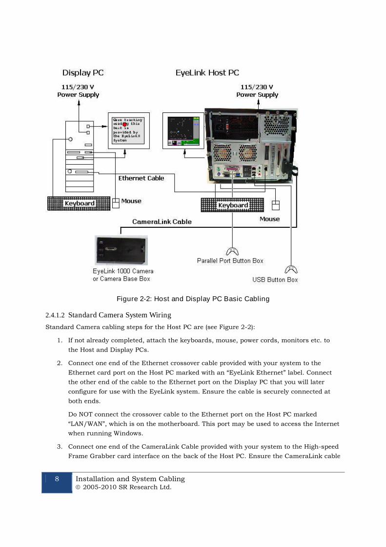
Figure 2-2: Host and Display PC Basic Cabling
2.4.1.2 Standard Camera System Wiring
Standard Camera cabling steps for the Host PC are (see Figure 2-2):
1. If not already completed, attach the keyboards, mouse, power cords, monitors etc. to
the Host and Display PCs.
2. Connect one end of the Ethernet crossover cable provided with your system to the
Ethernet card port on the Host PC marked with an “EyeLink Ethernet” label. Connect
the other end of the cable to the Ethernet port on the Display PC that you will later
configure for use with the EyeLink system. Ensure the cable is securely connected at
both ends.
Do NOT connect the crossover cable to the Ethernet port on the Host PC marked
“LAN/WAN”, which is on the motherboard. This port may be used to access the Internet
when running Windows.
3. Connect one end of the CameraLink Cable provided with your system to the High-speed
Frame Grabber card interface on the back of the Host PC. Ensure the CameraLink cable
Installation and System Cabling 2005-2010 SR Research Ltd.
9
is firmly attached with the two thumb screws tightened to lock the cable in place. A
slotted screwdriver may make this task easier.
The other end of the CameraLink Cable will be attached to the Standard Camera once it
is placed in its Mount.
4. Plug the 12V power supply’s small, circular end into the standard EyeLink 1000
camera. Plug the other end of the power supply into a surge protected power source.
The camera is powered as soon as it has an electrical supply, so a power supply with a
switch provides a convenient way to turn the camera on and off.
Continue on to 2.4.4 EyeLink Response Device Installation
10 Installation and System Cabling 2005-2010 SR Research Ltd.
2.4.2 Fiber Optic Camera System Installation
In general, the Fiber Optic Camera Head should be powered before the Camera Base
Box and the Host PC. Should the camera be unresponsive, power off the Camera Head
and then re-power it so that Camera Head is powered before the Camera Base Box.
2.4.2.1 Fiber Optic Camera Pre-installation Checklist
Ensure that you have the following listed components before you start installation.
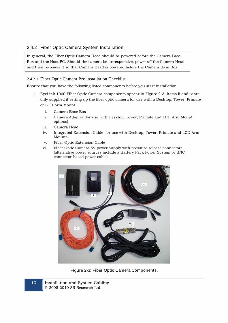
1. EyeLink 1000 Fiber Optic Camera components appear in Figure 2-3. Items ii and iv are
only supplied if setting up the fiber optic camera for use with a Desktop, Tower, Primate
or LCD Arm Mount.
i. Camera Base Box
ii. Camera Adapter (for use with Desktop, Tower, Primate and LCD Arm Mountoptions)
iii. Camera Head
iv. Integrated Extension Cable (for use with Desktop, Tower, Primate and LCD ArmMounts)
v. Fiber Optic Extension Cable
vi. Fiber Optic Camera 5V power supply with pressure-release connectors(alternative power sources include a Battery Pack Power System or BNCconnector-based power cable)
Figure 2-3: Fiber Optic Camera Components.

Installation and System Cabling 2005-2010 SR Research Ltd.
11
2. EyeLink 1000 Mount. Each type of Mount consists of an infrared illumination source
and an apparatus for holding the EyeLink 1000 camera. Each Mount option has a
separate chapter to be consulted regarding its installation. Mount types for the Fiber
Optic Camera include the Desktop, Tower, LCD Arm, Primate and Long Range Mounts.
3. 12V Power supply for the EyeLink 1000 Fiber Optic Camera Base Box.
4. CameraLink cable to connect Camera Base Box to High-Speed Frame Grabber card.
5. Crossover Ethernet cable to connect Host and Display PC together.
6. EyeLink Host PC – if your system did not come with a preconfigured Host PC, or if you
wish to replace the Host PC, see Section 2.2 for more information.
You will need to supply the following components:
1. A power strip with surge protection to ensure that your EyeLink receives consistent
voltage and to make it easy to power the system on and off.
2. A Display PC that ideally meets the required specifications. These specifications are
listed in section 1.3.2.
3. Some tools may be needed to adjust your mount or tighten cabling (usually a Phillips
and/or slotted/flathead screwdriver will do).
2.4.2.2 Fiber Optic Camera System Wiring
Fiber Optic Camera cabling steps are (see Figure 2-2):
1. If not already completed, attach the keyboards, mouse, power cords, monitors etc. to
the Host and Display PCs.
2. Connect one end of the Ethernet crossover cable provided with your system to the
Ethernet card port on the Host PC marked with an “EyeLink Ethernet” label. Connect
the other end of the cable to the Ethernet port on the Display PC that you will later
configure for use with the EyeLink system. Ensure the cable is securely connected at
both ends.
Do NOT connect the crossover cable to the Ethernet port on the Host PC marked
“LAN/WAN”, which is on the motherboard. This port may be used to access the Internet
when running Windows.
3. Connect one end of the CameraLink Cable provided with your system to the High-Speed
Frame Grabber card interface on the back of the Host PC. Attach the other end of the
CameraLink cable to the Camera Base Box for the Fiber Optic Camera. Affix the Camera
Base Box to the Velcro strips on the rear left side of your Host PC as pictured in Figure
2-4.
Ensure both ends of the CameraLink cable are firmly attached, with the two thumb
screws tightened to lock the cable in place. A slotted screwdriver may make this task
easier.
12 Installation and System Cabling 2005-2010 SR Research Ltd.
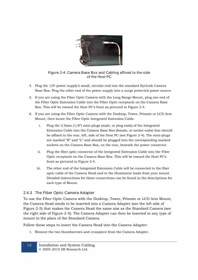
Figure 2-4: Camera Base Box and Cabling affixed to the sideof the Host PC
4. Plug the 12V power supply’s small, circular end into the standard EyeLink Camera
Base Box. Plug the other end of the power supply into a surge protected power source.
5. If you are using the Fiber Optic Camera with the Long Range Mount, plug one end of
the Fiber Optic Extension Cable into the Fiber Optic receptacle on the Camera Base
Box. This will be toward the Host PC’s front as pictured in Figure 2-4.
6. If you are using the Fiber Optic Camera with the Desktop, Tower, Primate or LCD Arm
Mount, then locate the Fiber Optic Integrated Extension Cable.
i. Plug the 3.5mm (1/8”) mini-plugs (male, or plug ends) of the Integrated
Extension Cable into the Camera Base Box (female, or socket ends) that should
be affixed to the rear, left, side of the Host PC (see Figure 2-4). The mini-plugs
are marked “R” and “L” and should be plugged into the corresponding marked
sockets on the Camera Base Box, on the rear, beneath the power connector.
ii. Plug the fiber optic connector of the Integrated Extension Cable into the Fiber
Optic receptacle on the Camera Base Box. This will be toward the Host PC’s
front as pictured in Figure 2-4.
iii. The other end of the Integrated Extension Cable will be connected to the fiber
optic cable of the Camera Head and to the illuminator leads from your mount.
Detailed instructions for these connections can be found in the descriptions for
each type of Mount.
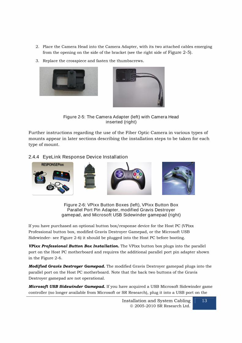
2.4.3 The Fiber Optic Camera Adapter
To use the Fiber Optic Camera with the Desktop, Tower, Primate or LCD Arm Mount,
the Camera Head needs to be inserted into a Camera Adapter (see the left side of
Figure 2-5) that makes the Camera Head the same size as the Standard Camera (see
the right side of Figure 2-5). The Camera Adapter can then be inserted in any type of
mount in the place of the Standard Camera.
Follow these steps to insert the Camera Head into the Camera Adapter:
1. Remove the two thumbscrews and crosspiece from the Camera Adapter.
Installation and System Cabling 2005-2010 SR Research Ltd.
13
2. Place the Camera Head into the Camera Adapter, with its two attached cables emerging
from the opening on the side of the bracket (see the right side of Figure 2-5).
3. Replace the crosspiece and fasten the thumbscrews.
Figure 2-5: The Camera Adapter (left) with Camera Headinserted (right)
Further instructions regarding the use of the Fiber Optic Camera in various types of
mounts appear in later sections describing the installation steps to be taken for each
type of mount.
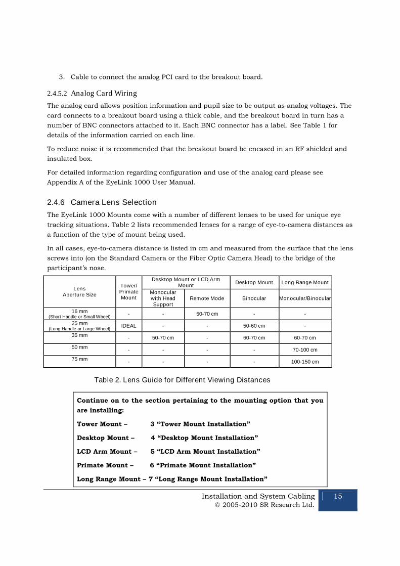
2.4.4 EyeLink Response Device Installation
Figure 2-6: VPixx Button Boxes (left), VPixx Button BoxParallel Port Pin Adapter, modified Gravis Destroyer
gamepad, and Microsoft USB Sidewinder gamepad (right)
If you have purchased an optional button box/response device for the Host PC (VPixx
Professional button box, modified Gravis Destroyer Gamepad, or the Microsoft USB
Sidewinder- see Figure 2-6) it should be plugged into the Host PC before booting.
VPixx Professional Button Box Installation. The VPixx button box plugs into the parallel
port on the Host PC motherboard and requires the additional parallel port pin adapter shown
in the Figure 2-6.
Modified Gravis Destroyer Gamepad. The modified Gravis Destroyer gamepad plugs into the
parallel port on the Host PC motherboard. Note that the back two buttons of the Gravis
Destroyer gamepad are not operational.
Microsoft USB Sidewinder Gamepad. If you have acquired a USB Microsoft Sidewinder game
controller (no longer available from Microsoft or SR Research), plug it into a USB port on the

14 Installation and System Cabling 2005-2010 SR Research Ltd.
back of the Host PC as indicated by the label “EyeLink Button Box”. Use an optional USB
extender cable if the game pad needs to have a cord longer than one meter.
NOTE: If you have a USB Button Box, it must be directly connected to a
USB port on the Host PC and cannot be connected through a USB hub.
Use of an Optional Parallel Port Expansion Card. The EyeLink Host PC can be used with
an optional Parallel Port Expansion Card from SR Research. While the default configuration
expects the VPixx Button Box or Modified gravis Destroyer Gamepad to be plugged into the
motherboard’s parallel port, it is possible to use these with the expansion card by copying and
renaming the {EYELINK Drive}:\ELCL\EXE\BUTTONS.EXP file as {EYELINK
Drive}:\ELCL\EXE\BUTTONS.INI – which configures the expansion port as the default.
BNC Connector Label Eye Data Line
0 Monocular: X DAC0
Binocular: Left X
1 Monocular: Y DAC1
Binocular: Left Y
2 Monocular: Pupil Size DAC2
Binocular: Left Pupil Size
3 Monocular: - DAC3
Binocular: Right X
4 Monocular: - DAC4
Binocular: Right Y
5 Monocular: - DAC5
Binocular: Right Pupil Size
STST Strobe Line STST
Table 1: Analog Card BNC Connector Information
2.4.5 Analog Card Installation
If an optional Data Translation analog card was purchased with your system it will require
additional cabling steps.
2.4.5.1 Analog Card Pre-installation Checklist
If an analog card option was purchased, you should also have:
1. Full length PCI Analog card (already seated in the Host PC if your system comes
preconfigured).
2. Analog breakout board with BNC connectors.
Installation and System Cabling 2005-2010 SR Research Ltd.
15
3. Cable to connect the analog PCI card to the breakout board.
2.4.5.2 Analog Card Wiring
The analog card allows position information and pupil size to be output as analog voltages. The
card connects to a breakout board using a thick cable, and the breakout board in turn has a
number of BNC connectors attached to it. Each BNC connector has a label. See Table 1 for
details of the information carried on each line.
To reduce noise it is recommended that the breakout board be encased in an RF shielded and
insulated box.
For detailed information regarding configuration and use of the analog card please see
Appendix A of the EyeLink 1000 User Manual.
2.4.6 Camera Lens Selection
The EyeLink 1000 Mounts come with a number of different lenses to be used for unique eye
tracking situations. Table 2 lists recommended lenses for a range of eye-to-camera distances as
a function of the type of mount being used.
In all cases, eye-to-camera distance is listed in cm and measured from the surface that the lens
screws into (on the Standard Camera or the Fiber Optic Camera Head) to the bridge of the
participant’s nose.
LensAperture Size
Tower/PrimateMount
Desktop Mount or LCD ArmMount
Desktop Mount Long Range Mount
Monocularwith HeadSupport
Remote Mode Binocular Monocular/Binocular
16 mm(Short Handle or Small Wheel)
- - 50-70 cm - -
25 mm(Long Handle or Large Wheel)
IDEAL - - 50-60 cm -
35 mm - 50-70 cm - 60-70 cm 60-70 cm
50 mm- - - - 70-100 cm
75 mm- - - - 100-150 cm
Table 2. Lens Guide for Different Viewing Distances
Continue on to the section pertaining to the mounting option that you
are installing:
Tower Mount – 3 “Tower Mount Installation”
Desktop Mount – 4 “Desktop Mount Installation”
LCD Arm Mount – 5 “LCD Arm Mount Installation”
Primate Mount – 6 “Primate Mount Installation”
Long Range Mount – 7 “Long Range Mount Installation”
16 Tower Mount Installation 2005-2010 SR Research Ltd.
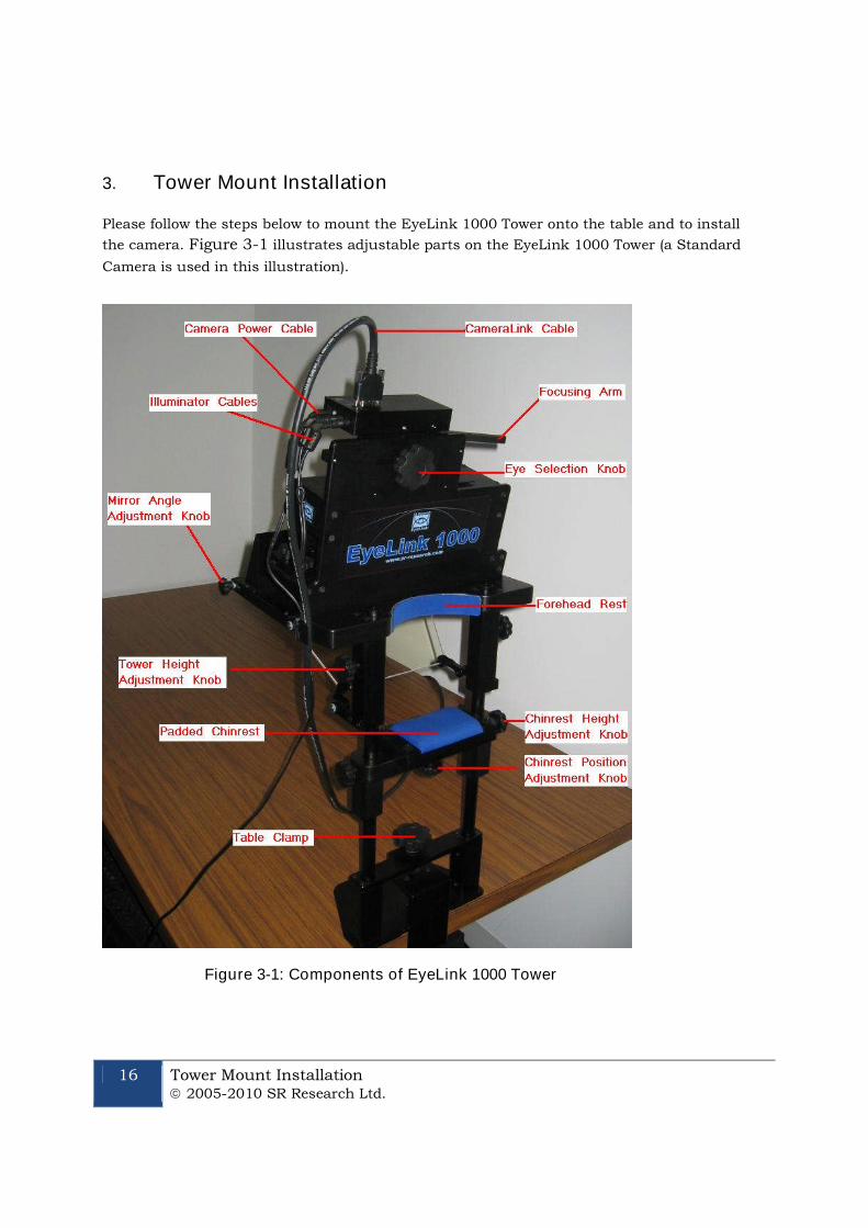
3. Tower Mount Installation
Please follow the steps below to mount the EyeLink 1000 Tower onto the table and to install
the camera. Figure 3-1 illustrates adjustable parts on the EyeLink 1000 Tower (a Standard
Camera is used in this illustration).
Figure 3-1: Components of EyeLink 1000 Tower
Tower Mount Installation 2005-2010 SR Research Ltd.
17
3.1 Mounting the Tower to a Table
Important: The head support Tower should only be held by the vertical
posts and should NEVER be held by the mirror or the components
attached to the mirror. We recommend you have somebody available to
assist with mounting the head-support Tower onto the table to prevent
damages to the IR mirror or other parts of the Tower.
Check whether the table is suitable for mounting the EyeLink 1000 Tower – the table used
should have a minimum thickness of 1.8 cm and a maximum thickness of 8.0 cm.
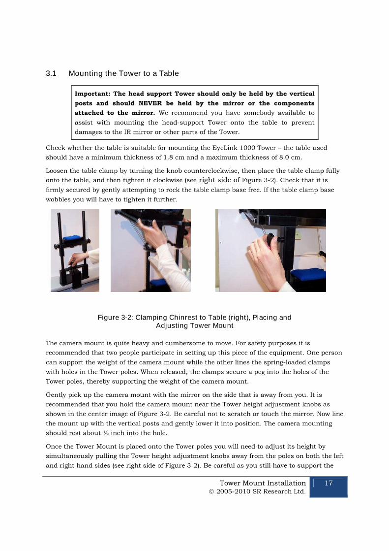
Loosen the table clamp by turning the knob counterclockwise, then place the table clamp fully
onto the table, and then tighten it clockwise (see right side of Figure 3-2). Check that it is
firmly secured by gently attempting to rock the table clamp base free. If the table clamp base
wobbles you will have to tighten it further.
Figure 3-2: Clamping Chinrest to Table (right), Placing andAdjusting Tower Mount
The camera mount is quite heavy and cumbersome to move. For safety purposes it is
recommended that two people participate in setting up this piece of the equipment. One person
can support the weight of the camera mount while the other lines the spring-loaded clamps
with holes in the Tower poles. When released, the clamps secure a peg into the holes of the
Tower poles, thereby supporting the weight of the camera mount.
Gently pick up the camera mount with the mirror on the side that is away from you. It is
recommended that you hold the camera mount near the Tower height adjustment knobs as
shown in the center image of Figure 3-2. Be careful not to scratch or touch the mirror. Now line
the mount up with the vertical posts and gently lower it into position. The camera mounting
should rest about ½ inch into the hole.
Once the Tower Mount is placed onto the Tower poles you will need to adjust its height by
simultaneously pulling the Tower height adjustment knobs away from the poles on both the left
and right hand sides (see right side of Figure 3-2). Be careful as you still have to support the
18 Tower Mount Installation 2005-2010 SR Research Ltd.
weight of the camera mounting unit. Make sure that the unit does not fall down the poles. If at
any point the camera mounting unit does begin to fall, releasing the spring-loaded height
adjustment will cause them to lock into one set of holes in the Tower poles, preventing the
Tower from falling further.
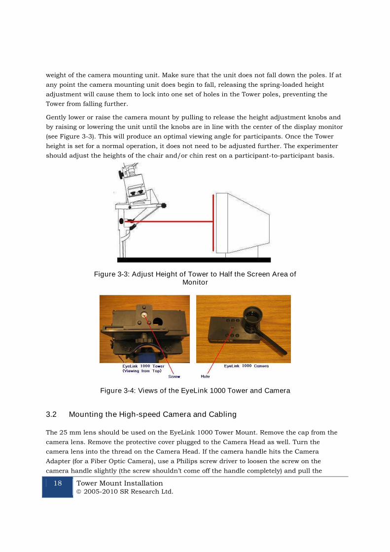
Gently lower or raise the camera mount by pulling to release the height adjustment knobs and
by raising or lowering the unit until the knobs are in line with the center of the display monitor
(see Figure 3-3). This will produce an optimal viewing angle for participants. Once the Tower
height is set for a normal operation, it does not need to be adjusted further. The experimenter
should adjust the heights of the chair and/or chin rest on a participant-to-participant basis.
Figure 3-3: Adjust Height of Tower to Half the Screen Area ofMonitor
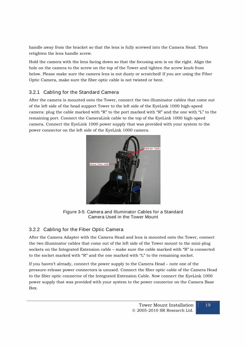
Figure 3-4: Views of the EyeLink 1000 Tower and Camera
3.2 Mounting the High-speed Camera and Cabling
The 25 mm lens should be used on the EyeLink 1000 Tower Mount. Remove the cap from the
camera lens. Remove the protective cover plugged to the Camera Head as well. Turn the
camera lens into the thread on the Camera Head. If the camera handle hits the Camera
Adapter (for a Fiber Optic Camera), use a Philips screw driver to loosen the screw on the
camera handle slightly (the screw shouldn’t come off the handle completely) and pull the
Tower Mount Installation 2005-2010 SR Research Ltd.
19
handle away from the bracket so that the lens is fully screwed into the Camera Head. Then
retighten the lens handle screw.
Hold the camera with the lens facing down so that the focusing arm is on the right. Align the
hole on the camera to the screw on the top of the Tower and tighten the screw knob from
below. Please make sure the camera lens is not dusty or scratched! If you are using the Fiber
Optic Camera, make sure the fiber optic cable is not twisted or bent.
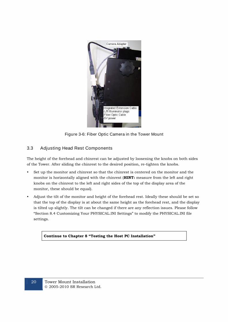
3.2.1 Cabling for the Standard Camera
After the camera is mounted onto the Tower, connect the two illuminator cables that come out
of the left side of the head support Tower to the left side of the EyeLink 1000 high-speed
camera: plug the cable marked with “R” to the port marked with “R” and the one with “L” to the
remaining port. Connect the CameraLink cable to the top of the EyeLink 1000 high-speed
camera. Connect the EyeLink 1000 power supply that was provided with your system to the
power connector on the left side of the EyeLink 1000 camera.
Figure 3-5: Camera and Illuminator Cables for a StandardCamera Used in the Tower Mount
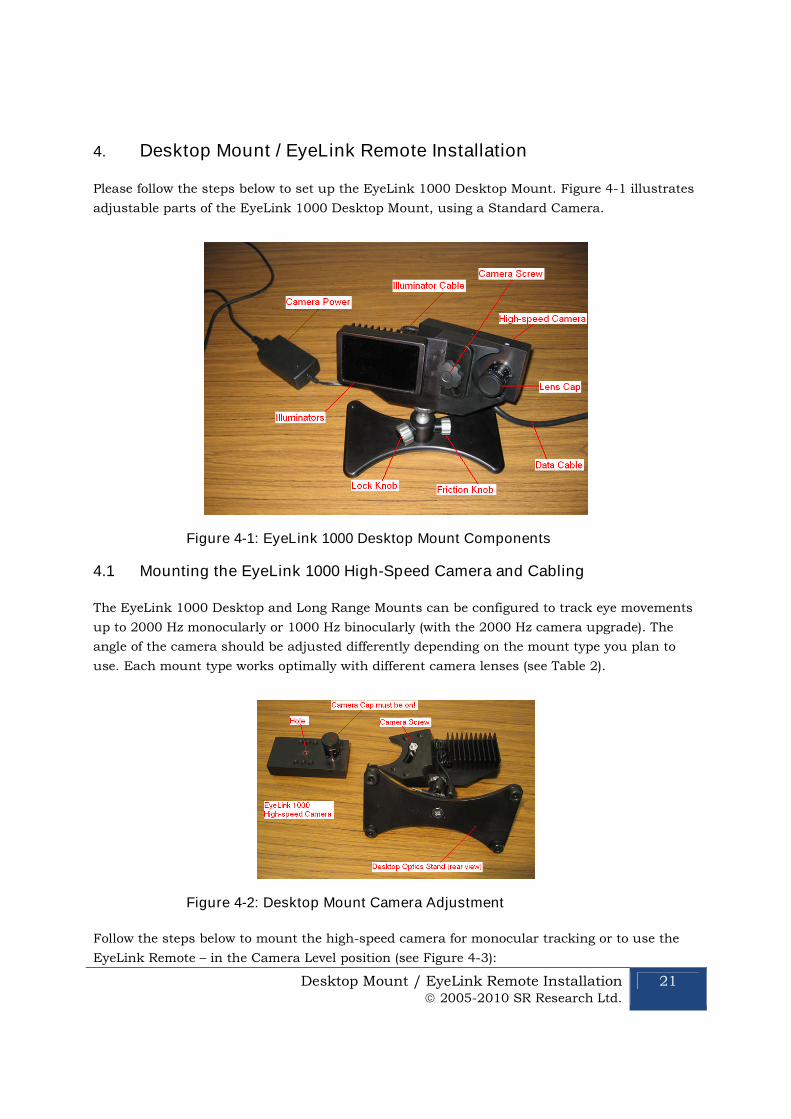
3.2.2 Cabling for the Fiber Optic Camera
After the Camera Adapter with the Camera Head and lens is mounted onto the Tower, connect
the two illuminator cables that come out of the left side of the Tower mount to the mini-plug
sockets on the Integrated Extension cable – make sure the cable marked with “R” is connected
to the socket marked with “R” and the one marked with “L” to the remaining socket.
If you haven’t already, connect the power supply to the Camera Head – note one of the
pressure-release power connectors is unused. Connect the fiber optic cable of the Camera Head
to the fiber optic connector of the Integrated Extension Cable. Now connect the EyeLink 1000
power supply that was provided with your system to the power connector on the Camera Base
Box.
20 Tower Mount Installation 2005-2010 SR Research Ltd.
Figure 3-6: Fiber Optic Camera in the Tower Mount
3.3 Adjusting Head Rest Components
The height of the forehead and chinrest can be adjusted by loosening the knobs on both sides
of the Tower. After sliding the chinrest to the desired position, re-tighten the knobs.
Set up the monitor and chinrest so that the chinrest is centered on the monitor and the
monitor is horizontally aligned with the chinrest (HINT: measure from the left and right
knobs on the chinrest to the left and right sides of the top of the display area of the
monitor, these should be equal).
Adjust the tilt of the monitor and height of the forehead rest. Ideally these should be set so
that the top of the display is at about the same height as the forehead rest, and the display
is tilted up slightly. The tilt can be changed if there are any reflection issues. Please follow
“Section 8.4 Customizing Your PHYSICAL.INI Settings” to modify the PHYSICAL.INI file
settings.
Continue to Chapter 8 “Testing the Host PC Installation”
Desktop Mount / EyeLink Remote Installation 2005-2010 SR Research Ltd.
21
4. Desktop Mount / EyeLink Remote Installation
Please follow the steps below to set up the EyeLink 1000 Desktop Mount. Figure 4-1 illustrates
adjustable parts of the EyeLink 1000 Desktop Mount, using a Standard Camera.
Figure 4-1: EyeLink 1000 Desktop Mount Components
4.1 Mounting the EyeLink 1000 High-Speed Camera and Cabling
The EyeLink 1000 Desktop and Long Range Mounts can be configured to track eye movements
up to 2000 Hz monocularly or 1000 Hz binocularly (with the 2000 Hz camera upgrade). The
angle of the camera should be adjusted differently depending on the mount type you plan to
use. Each mount type works optimally with different camera lenses (see Table 2).
Figure 4-2: Desktop Mount Camera Adjustment
Follow the steps below to mount the high-speed camera for monocular tracking or to use the
EyeLink Remote – in the Camera Level position (see Figure 4-3):
22 Desktop Mount / EyeLink Remote Installation 2005-2010 SR Research Ltd.
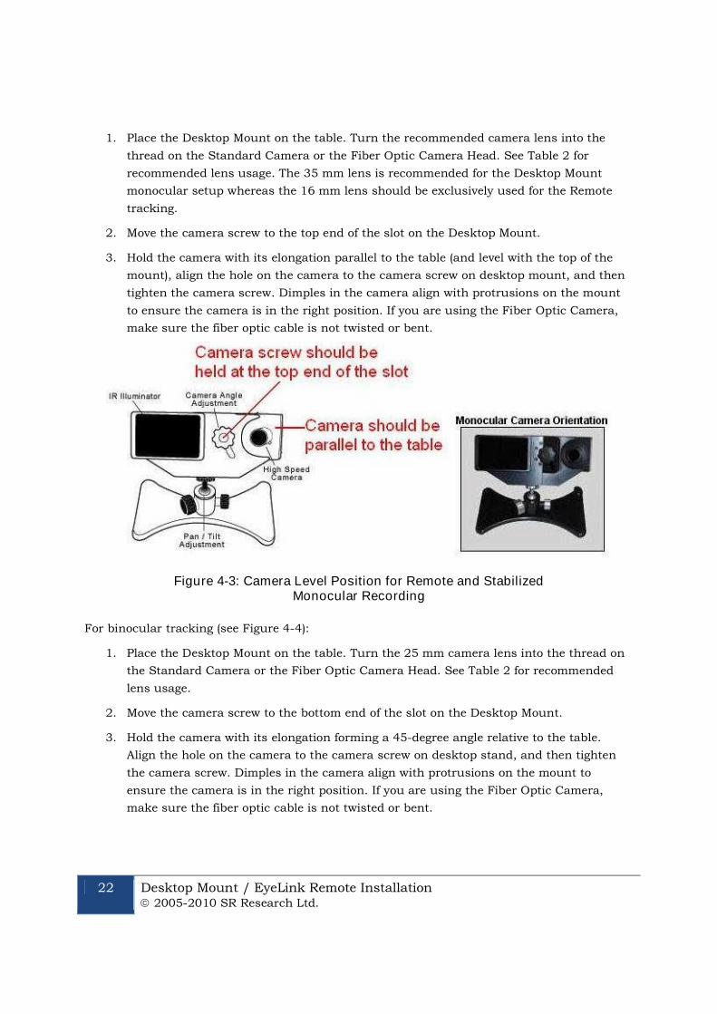
1. Place the Desktop Mount on the table. Turn the recommended camera lens into the
thread on the Standard Camera or the Fiber Optic Camera Head. See Table 2 for
recommended lens usage. The 35 mm lens is recommended for the Desktop Mount
monocular setup whereas the 16 mm lens should be exclusively used for the Remote
tracking.
2. Move the camera screw to the top end of the slot on the Desktop Mount.
3. Hold the camera with its elongation parallel to the table (and level with the top of the
mount), align the hole on the camera to the camera screw on desktop mount, and then
tighten the camera screw. Dimples in the camera align with protrusions on the mount
to ensure the camera is in the right position. If you are using the Fiber Optic Camera,
make sure the fiber optic cable is not twisted or bent.
Figure 4-3: Camera Level Position for Remote and StabilizedMonocular Recording
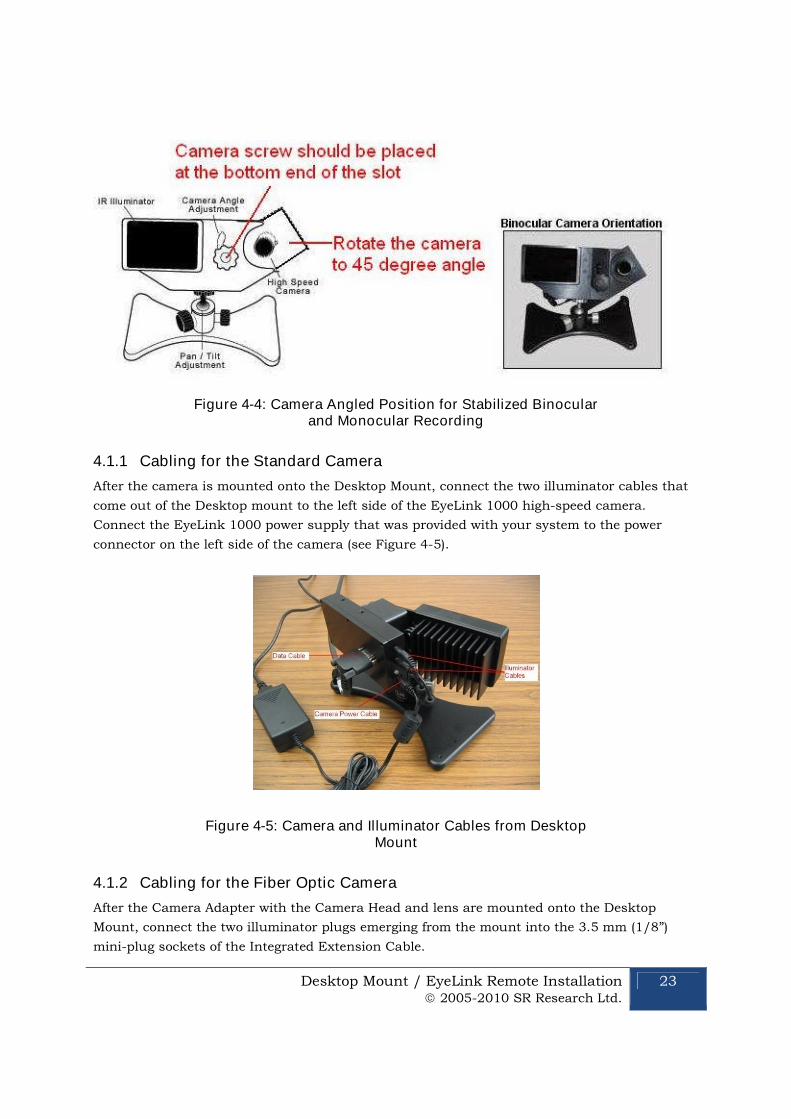
For binocular tracking (see Figure 4-4):
1. Place the Desktop Mount on the table. Turn the 25 mm camera lens into the thread on
the Standard Camera or the Fiber Optic Camera Head. See Table 2 for recommended
lens usage.
2. Move the camera screw to the bottom end of the slot on the Desktop Mount.
3. Hold the camera with its elongation forming a 45-degree angle relative to the table.
Align the hole on the camera to the camera screw on desktop stand, and then tighten
the camera screw. Dimples in the camera align with protrusions on the mount to
ensure the camera is in the right position. If you are using the Fiber Optic Camera,
make sure the fiber optic cable is not twisted or bent.
Desktop Mount / EyeLink Remote Installation 2005-2010 SR Research Ltd.
23
Figure 4-4: Camera Angled Position for Stabilized Binocularand Monocular Recording
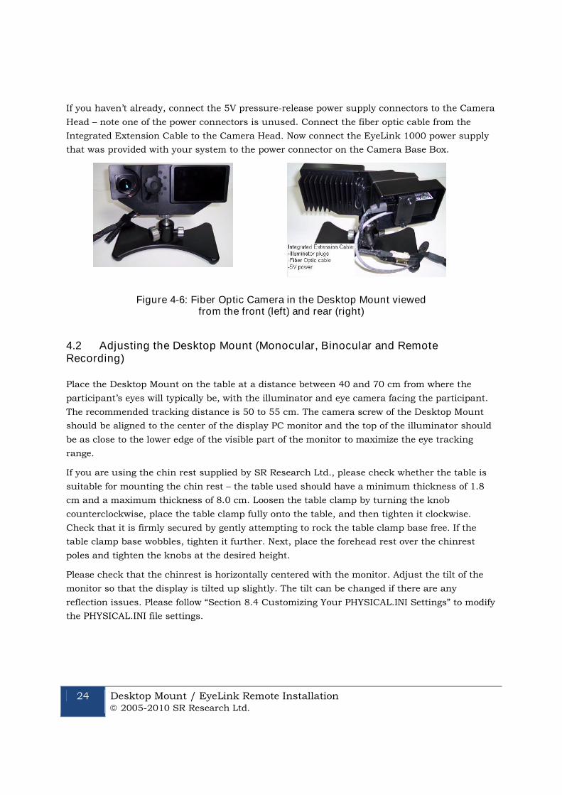
4.1.1 Cabling for the Standard Camera
After the camera is mounted onto the Desktop Mount, connect the two illuminator cables that
come out of the Desktop mount to the left side of the EyeLink 1000 high-speed camera.
Connect the EyeLink 1000 power supply that was provided with your system to the power
connector on the left side of the camera (see Figure 4-5).
Figure 4-5: Camera and Illuminator Cables from DesktopMount
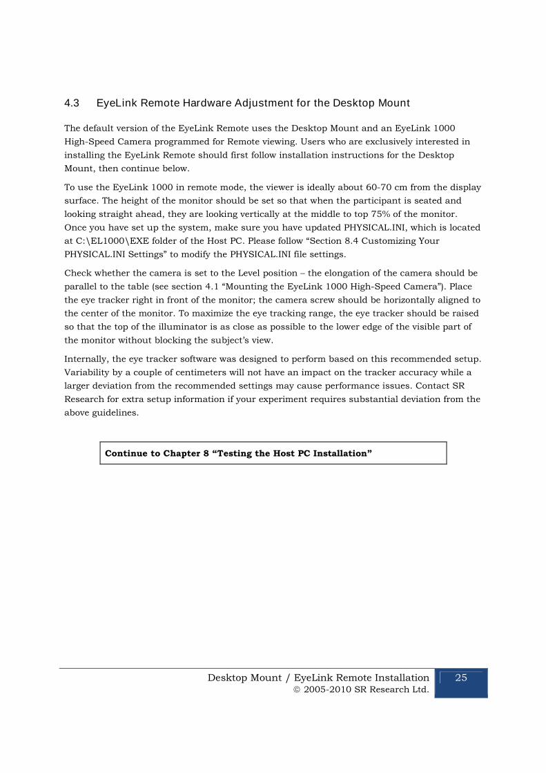
4.1.2 Cabling for the Fiber Optic Camera
After the Camera Adapter with the Camera Head and lens are mounted onto the Desktop
Mount, connect the two illuminator plugs emerging from the mount into the 3.5 mm (1/8”)
mini-plug sockets of the Integrated Extension Cable.
24 Desktop Mount / EyeLink Remote Installation 2005-2010 SR Research Ltd.
If you haven’t already, connect the 5V pressure-release power supply connectors to the Camera
Head – note one of the power connectors is unused. Connect the fiber optic cable from the
Integrated Extension Cable to the Camera Head. Now connect the EyeLink 1000 power supply
that was provided with your system to the power connector on the Camera Base Box.
Figure 4-6: Fiber Optic Camera in the Desktop Mount viewedfrom the front (left) and rear (right)
4.2 Adjusting the Desktop Mount (Monocular, Binocular and RemoteRecording)
Place the Desktop Mount on the table at a distance between 40 and 70 cm from where the
participant’s eyes will typically be, with the illuminator and eye camera facing the participant.
The recommended tracking distance is 50 to 55 cm. The camera screw of the Desktop Mount
should be aligned to the center of the display PC monitor and the top of the illuminator should
be as close to the lower edge of the visible part of the monitor to maximize the eye tracking
range.
If you are using the chin rest supplied by SR Research Ltd., please check whether the table is
suitable for mounting the chin rest – the table used should have a minimum thickness of 1.8
cm and a maximum thickness of 8.0 cm. Loosen the table clamp by turning the knob
counterclockwise, place the table clamp fully onto the table, and then tighten it clockwise.
Check that it is firmly secured by gently attempting to rock the table clamp base free. If the
table clamp base wobbles, tighten it further. Next, place the forehead rest over the chinrest
poles and tighten the knobs at the desired height.
Please check that the chinrest is horizontally centered with the monitor. Adjust the tilt of the
monitor so that the display is tilted up slightly. The tilt can be changed if there are any
reflection issues. Please follow “Section 8.4 Customizing Your PHYSICAL.INI Settings” to modify
the PHYSICAL.INI file settings.
Desktop Mount / EyeLink Remote Installation 2005-2010 SR Research Ltd.
25
4.3 EyeLink Remote Hardware Adjustment for the Desktop Mount
The default version of the EyeLink Remote uses the Desktop Mount and an EyeLink 1000
High-Speed Camera programmed for Remote viewing. Users who are exclusively interested in
installing the EyeLink Remote should first follow installation instructions for the Desktop
Mount, then continue below.
To use the EyeLink 1000 in remote mode, the viewer is ideally about 60-70 cm from the display
surface. The height of the monitor should be set so that when the participant is seated and
looking straight ahead, they are looking vertically at the middle to top 75% of the monitor.
Once you have set up the system, make sure you have updated PHYSICAL.INI, which is located
at C:\EL1000\EXE folder of the Host PC. Please follow “Section 8.4 Customizing Your
PHYSICAL.INI Settings” to modify the PHYSICAL.INI file settings.
Check whether the camera is set to the Level position – the elongation of the camera should be
parallel to the table (see section 4.1 “Mounting the EyeLink 1000 High-Speed Camera”). Place
the eye tracker right in front of the monitor; the camera screw should be horizontally aligned to
the center of the monitor. To maximize the eye tracking range, the eye tracker should be raised
so that the top of the illuminator is as close as possible to the lower edge of the visible part of
the monitor without blocking the subject’s view.
Internally, the eye tracker software was designed to perform based on this recommended setup.
Variability by a couple of centimeters will not have an impact on the tracker accuracy while a
larger deviation from the recommended settings may cause performance issues. Contact SR
Research for extra setup information if your experiment requires substantial deviation from the
above guidelines.
Continue to Chapter 8 “Testing the Host PC Installation”
26 LCD Arm Mount Installation 2005-2010 SR Research Ltd.
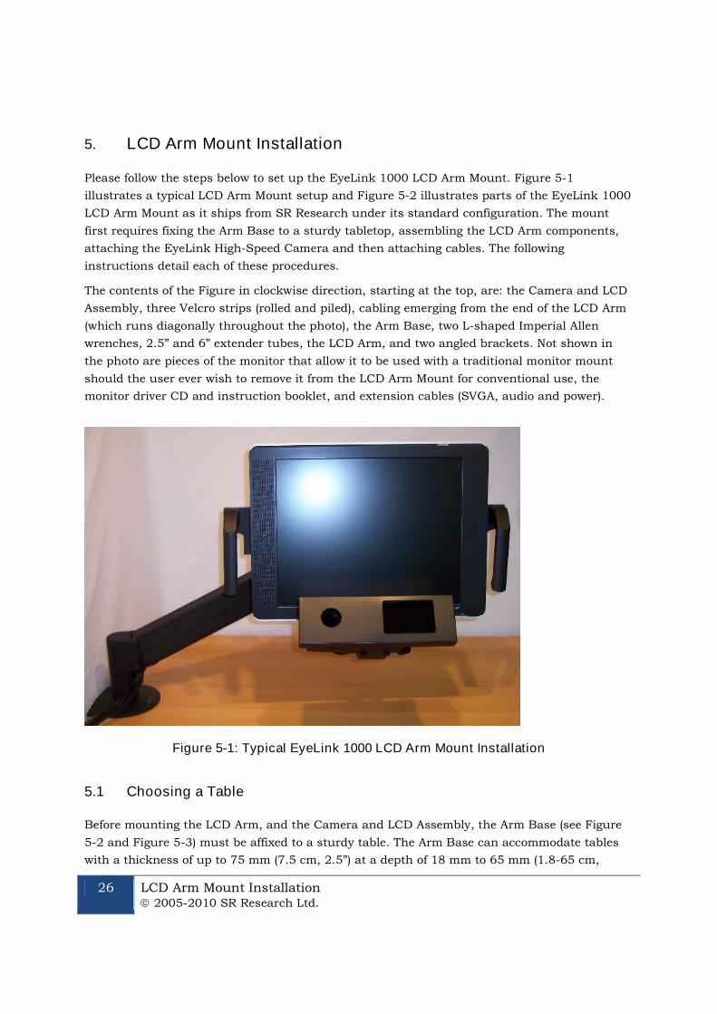
5. LCD Arm Mount Installation
Please follow the steps below to set up the EyeLink 1000 LCD Arm Mount. Figure 5-1
illustrates a typical LCD Arm Mount setup and Figure 5-2 illustrates parts of the EyeLink 1000
LCD Arm Mount as it ships from SR Research under its standard configuration. The mount
first requires fixing the Arm Base to a sturdy tabletop, assembling the LCD Arm components,
attaching the EyeLink High-Speed Camera and then attaching cables. The following
instructions detail each of these procedures.
The contents of the Figure in clockwise direction, starting at the top, are: the Camera and LCD
Assembly, three Velcro strips (rolled and piled), cabling emerging from the end of the LCD Arm
(which runs diagonally throughout the photo), the Arm Base, two L-shaped Imperial Allen
wrenches, 2.5” and 6” extender tubes, the LCD Arm, and two angled brackets. Not shown in
the photo are pieces of the monitor that allow it to be used with a traditional monitor mount
should the user ever wish to remove it from the LCD Arm Mount for conventional use, the
monitor driver CD and instruction booklet, and extension cables (SVGA, audio and power).
Figure 5-1: Typical EyeLink 1000 LCD Arm Mount Installation
5.1 Choosing a Table
Before mounting the LCD Arm, and the Camera and LCD Assembly, the Arm Base (see Figure
5-2 and Figure 5-3) must be affixed to a sturdy table. The Arm Base can accommodate tables
with a thickness of up to 75 mm (7.5 cm, 2.5”) at a depth of 18 mm to 65 mm (1.8-65 cm,
LCD Arm Mount Installation 2005-2010 SR Research Ltd.
27
1.25”). The footprint of the Arm Base above the table is 160 mm wide x 140 mm deep (16 cm or
6 ¼” X 14 cm or 5 ½”) and requires further clearance for the LCD Arm to swing in any
direction.
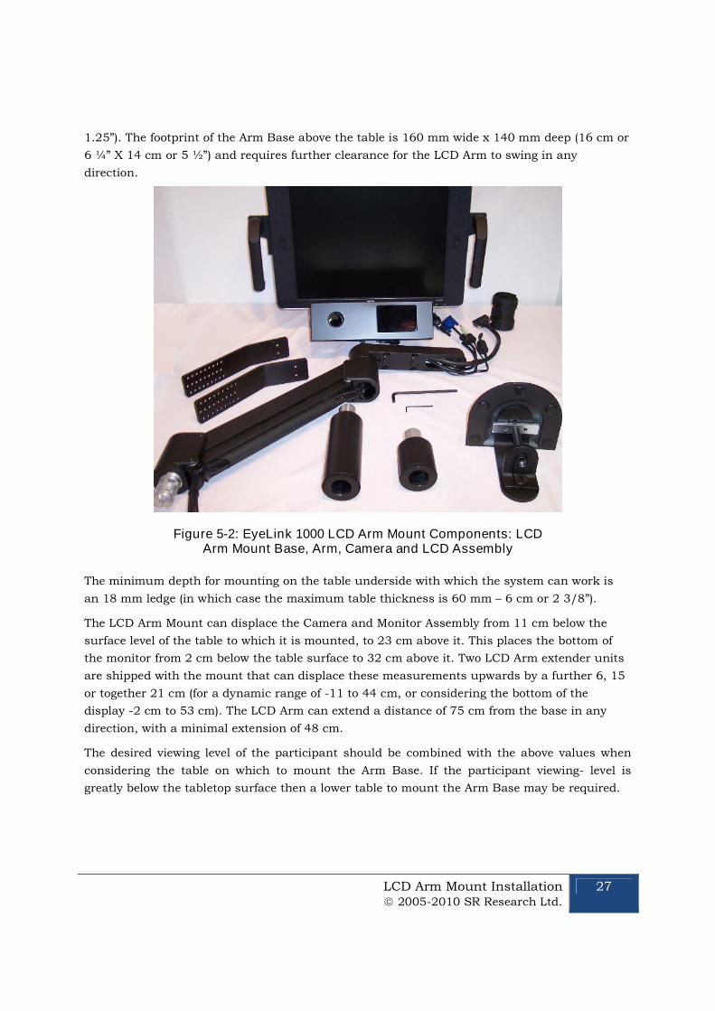
Figure 5-2: EyeLink 1000 LCD Arm Mount Components: LCDArm Mount Base, Arm, Camera and LCD Assembly
The minimum depth for mounting on the table underside with which the system can work is
an 18 mm ledge (in which case the maximum table thickness is 60 mm – 6 cm or 2 3/8”).
The LCD Arm Mount can displace the Camera and Monitor Assembly from 11 cm below the
surface level of the table to which it is mounted, to 23 cm above it. This places the bottom of
the monitor from 2 cm below the table surface to 32 cm above it. Two LCD Arm extender units
are shipped with the mount that can displace these measurements upwards by a further 6, 15
or together 21 cm (for a dynamic range of -11 to 44 cm, or considering the bottom of the
display -2 cm to 53 cm). The LCD Arm can extend a distance of 75 cm from the base in any
direction, with a minimal extension of 48 cm.
The desired viewing level of the participant should be combined with the above values when
considering the table on which to mount the Arm Base. If the participant viewing- level is
greatly below the tabletop surface then a lower table to mount the Arm Base may be required.
28 LCD Arm Mount Installation 2005-2010 SR Research Ltd.
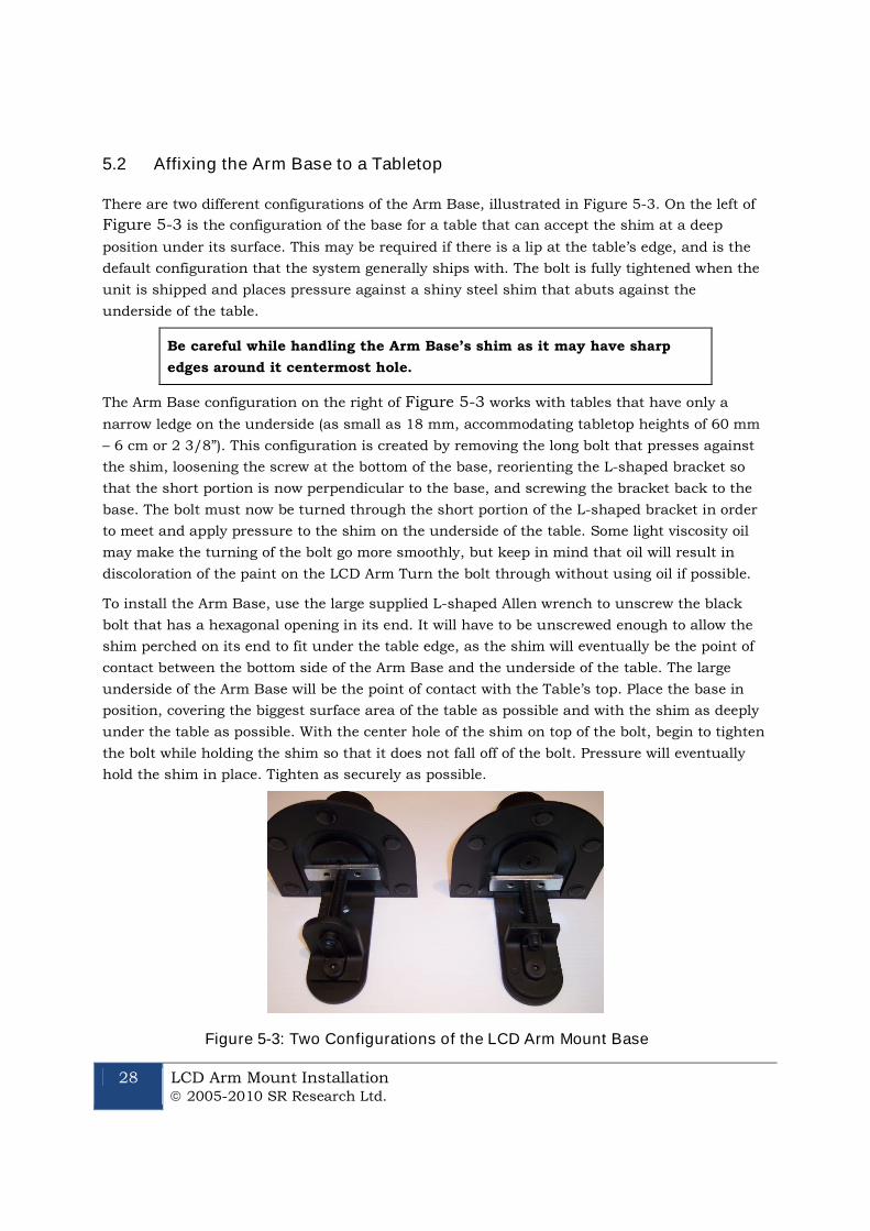
5.2 Affixing the Arm Base to a Tabletop
There are two different configurations of the Arm Base, illustrated in Figure 5-3. On the left of
Figure 5-3 is the configuration of the base for a table that can accept the shim at a deep
position under its surface. This may be required if there is a lip at the table’s edge, and is the
default configuration that the system generally ships with. The bolt is fully tightened when the
unit is shipped and places pressure against a shiny steel shim that abuts against the
underside of the table.
Be careful while handling the Arm Base’s shim as it may have sharp
edges around it centermost hole.
The Arm Base configuration on the right of Figure 5-3 works with tables that have only a
narrow ledge on the underside (as small as 18 mm, accommodating tabletop heights of 60 mm
– 6 cm or 2 3/8”). This configuration is created by removing the long bolt that presses against
the shim, loosening the screw at the bottom of the base, reorienting the L-shaped bracket so
that the short portion is now perpendicular to the base, and screwing the bracket back to the
base. The bolt must now be turned through the short portion of the L-shaped bracket in order
to meet and apply pressure to the shim on the underside of the table. Some light viscosity oil
may make the turning of the bolt go more smoothly, but keep in mind that oil will result in
discoloration of the paint on the LCD Arm Turn the bolt through without using oil if possible.
To install the Arm Base, use the large supplied L-shaped Allen wrench to unscrew the black
bolt that has a hexagonal opening in its end. It will have to be unscrewed enough to allow the
shim perched on its end to fit under the table edge, as the shim will eventually be the point of
contact between the bottom side of the Arm Base and the underside of the table. The large
underside of the Arm Base will be the point of contact with the Table’s top. Place the base in
position, covering the biggest surface area of the table as possible and with the shim as deeply
under the table as possible. With the center hole of the shim on top of the bolt, begin to tighten
the bolt while holding the shim so that it does not fall off of the bolt. Pressure will eventually
hold the shim in place. Tighten as securely as possible.
Figure 5-3: Two Configurations of the LCD Arm Mount Base

LCD Arm Mount Installation 2005-2010 SR Research Ltd.
29
5.3 Assembling the LCD Arm Components
Once the Arm Base has been secured to a sturdy tabletop, it is time to insert the LCD Arm into
the Arm Base. At this point you may wish to add one or both of the Arm Extenders that were
included with the system (2.5” and 6” extenders – 6 cm and 15 cm) as these raise the overall
height of the LCD Arm Mount. Note that using an extender will also raise the lowest point that
the LCD Arm Mount’s monitor can reach as they simply displace the entire unit vertically. The
extender shaft simply fits into the silver cup of the Arm Base or into the cup of another
extender.
Pick up the LCD Arm with one hand on each of the components to minimize its components
from swinging. The round silver shaft at the bottom of the arm fits into the silver cup at the top
of the Arm Base (or one of the optional extenders already inserted into the Arm Base) – simply
lower the LCD Arm straight into the cup, with cabling off to the side of the base that is closest
to the Display or Host PC to which the cabling will eventually be attached. Several pieces of
double-side Velcro ship with the LCD Arm Mount in order to assist users who may wish to
wrap the Velcro around the arm components to secure it before lifting. This can prevent the
arm from swinging while it is being moved.
The EyeLink 1000 LCD Arm Mount’s Camera and LCD Assembly holds an LCD computer
monitor, the EyeLink 1000 high-speed camera in the level position, and an infrared illuminator
light source. These are affixed as a single unit that can be easily lifted using handles that are
attached to each side of the LCD monitor. Facing the back of the monitor, grip the handles and
guide the shaft of the tilter mechanism into the hole at the top end of the arm. Gently wiggle
the assembly until the shaft is fully inserted into the arm.
Some configurations of the LCD Arm may require weights at the end of
the table opposite the Arm Base, to offset the weight of the LCD Arm
apparatus.
The LCD Arm is fairly heavy, with the entire apparatus weighing in at approximately 11 kg (or
25 lbs). Some possible configurations of the LCD Arm extend the monitor over empty space
away from the table’s edge, placing the weight of the Camera and Monitor Assembly away from
the support of the table. To prevent tipping, the table needs to be large, heavy and sturdy, or
weighted at the end opposite from which the LCD Arm will extend. Caution should be used
when first testing the range of the LCD Arm in case the table is not strong enough to properly
distribute the weight of the apparatus. If the table begins to tip while extending the LCD Arm
out into space away from the table, place the Arm apparatus back above the table surface and
add weight (e.g., the Display computer?) to the table surface opposite where the Arm is
extending. Repeat this procedure until it is clear that the apparatus is stable.
30 LCD Arm Mount Installation 2005-2010 SR Research Ltd.
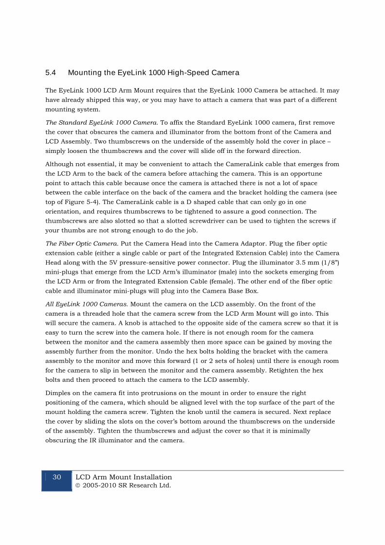
5.4 Mounting the EyeLink 1000 High-Speed Camera
The EyeLink 1000 LCD Arm Mount requires that the EyeLink 1000 Camera be attached. It may
have already shipped this way, or you may have to attach a camera that was part of a different
mounting system.
The Standard EyeLink 1000 Camera. To affix the Standard EyeLink 1000 camera, first remove
the cover that obscures the camera and illuminator from the bottom front of the Camera and
LCD Assembly. Two thumbscrews on the underside of the assembly hold the cover in place –
simply loosen the thumbscrews and the cover will slide off in the forward direction.
Although not essential, it may be convenient to attach the CameraLink cable that emerges from
the LCD Arm to the back of the camera before attaching the camera. This is an opportune
point to attach this cable because once the camera is attached there is not a lot of space
between the cable interface on the back of the camera and the bracket holding the camera (see
top of Figure 5-4). The CameraLink cable is a D shaped cable that can only go in one
orientation, and requires thumbscrews to be tightened to assure a good connection. The
thumbscrews are also slotted so that a slotted screwdriver can be used to tighten the screws if
your thumbs are not strong enough to do the job.
The Fiber Optic Camera. Put the Camera Head into the Camera Adaptor. Plug the fiber optic
extension cable (either a single cable or part of the Integrated Extension Cable) into the Camera
Head along with the 5V pressure-sensitive power connector. Plug the illuminator 3.5 mm (1/8”)
mini-plugs that emerge from the LCD Arm’s illuminator (male) into the sockets emerging from
the LCD Arm or from the Integrated Extension Cable (female). The other end of the fiber optic
cable and illuminator mini-plugs will plug into the Camera Base Box.
All EyeLink 1000 Cameras. Mount the camera on the LCD assembly. On the front of the
camera is a threaded hole that the camera screw from the LCD Arm Mount will go into. This
will secure the camera. A knob is attached to the opposite side of the camera screw so that it is
easy to turn the screw into the camera hole. If there is not enough room for the camera
between the monitor and the camera assembly then more space can be gained by moving the
assembly further from the monitor. Undo the hex bolts holding the bracket with the camera
assembly to the monitor and move this forward (1 or 2 sets of holes) until there is enough room
for the camera to slip in between the monitor and the camera assembly. Retighten the hex
bolts and then proceed to attach the camera to the LCD assembly.
Dimples on the camera fit into protrusions on the mount in order to ensure the right
positioning of the camera, which should be aligned level with the top surface of the part of the
mount holding the camera screw. Tighten the knob until the camera is secured. Next replace
the cover by sliding the slots on the cover’s bottom around the thumbscrews on the underside
of the assembly. Tighten the thumbscrews and adjust the cover so that it is minimally
obscuring the IR illuminator and the camera.
LCD Arm Mount Installation 2005-2010 SR Research Ltd.
31
Figure 5-4: Rearview of the LCD Arm Mount’s Camera (top)and LCD Monitor (bottom)
5.5 Attaching the Cables
Integrated into the LCD Arm Mount is the cabling required for the EyeLink 1000 system and
the computer monitor (camera and LCD monitor power cables, monitor audio cable, SVGA
video cable, and the CameraLink cable). After assembling the LCD Arm Mount components,
inserting the LCD Arm into the Arm Base, and attaching the camera, all of the cables need to
be connected.
For all cables emerging from the LCD Arm, location descriptions assume a view of the Camera
and LCD Assembly from the back underside of the monitor (see Figure 5-4, bottom). Guide the
cables to the side of the camera and illuminator support bracket to which the cable will
eventually be attached – this will prevent the cable from binding against the bracket when the
LCD Arm is twisted in various directions. Follow these steps:
1. First, let’s deal with cables attached to the high-speed camera (Figure 5-4 top).
If not already connected before affixing the camera, connect the CameraLink
cable to the interface on the back of the camera that is housed within the
Camera and LCD Assembly. Tighten the screws by thumb or use a slotted
screwdriver to tighten. Attaching this cable before attaching the camera to the
assembly may be easier for some users.
Insert the round EyeLink 1000 power supply cable to the power connector on
the right side of the camera.
Ensure that the two illuminator cables are plugged into the side of the EyeLink
1000 high-speed camera – placement is not important. These cables are present
on the Camera and LCD Assembly and do not emerge from the LCD Arm.
32 LCD Arm Mount Installation 2005-2010 SR Research Ltd.
2. The remaining cables emerging from the LCD Arm connect to the LCD monitor as
follows (Figure 5-4 bottom):
Insert the phono plug connector into the audio input jack on the bottom centre
of the LCD monitor of the Camera and LCD Assembly.
Connect the SVGA cable to the SVGA input on the right of the LCD monitor.
Tighten the screws by thumb or use a slotted screwdriver.
Connect the three-prong power cable into the LCD monitor power input on the
left side of the monitor.
Figure 5-5: Cables Emerging from the Bottom of the LCD Arm
3. The following cables coming out of the bottom of the LCD Arm (shown left-to-right in
Figure 5-5) are to be connected as described below. Extension cables are supplied as
indicated in the text above. The first cable is the camera high-speed data cable and goes
to the Host PC, the next two cables go to outputs on the Display PC, and the final two
go to a power source.
Connect the thick CameraLink cable emerging from the bottom of the LCD Arm
to the EyeLink card on the Host PC. Be sure to tighten the thumbscrew
connectors or use a slotted screwdriver to make a tight connection.
Connect the supplied SVGA extension cable to the SVGA cable coming out of the
bottom of the LCD Arm Mount. The female end of the cable coming from the
LCD Arm attaches to a male connector on the extension. The extension’s female
end attaches to the Display PC video card output port.
Connect the supplied audio cable extension (female end) to the 3.5 mm (1/8”)
mini-plug on the audio cable emerging from the bottom of the LCD Arm. Insert
the male end into the audio output jack on the Display PC.
Connect the supplied three-prong power cable (female end) to the camera power
supply (male end) that is attached to a cable coming from the bottom of the LCD
Arm. The male end plugs into a power source.
Connect the supplied three-prong power extension cable to the LCD monitor’s
power input and plug the male end into a power source. The power supply in the
LCD Arm Mount Installation 2005-2010 SR Research Ltd.
33
monitor is 110/220 Hz so an adapter may be used (supplied) for countries
outside of North America and Japan if the appropriate extension is not included.
4. One final cable needs to be attached. Connect one end of the Ethernet crossover cable
provided with your system to the Ethernet card port on the Host PC (make sure it is
connected to the EyeLink Ethernet port and not the Ethernet port that is built into the
motherboard). Connect the other end of the Ethernet cable to the Ethernet port on the
Display PC that you will later configure for use with the EyeLink system. Ensure the
cable is securely connected at both ends.
5.6 Adjusting the Tension Points on the LCD Arm
Occasionally through use of the LCD Arm some of the joints or the hydraulics may require
adjustment. Each joint can have the tension adjusted so as to require more or less force to
move.
Tension adjustment points are indicated by hexagonal screws on the LCD Arm and can be
adjusted using the Allen wrenches supplied. Recall that all hexagonal screws on the LCD Arm
are in Imperial units. Loosening a joint (typically turning counterclockwise) too much may
make it so that it does not stay in the desired position, so tighter tension (turning clockwise) is
generally preferred.
5.7 LCD Arm Mount Adjustments for Monocular and Remote Recording
The EyeLink 1000 LCD Arm Mount can be used for highly accurate monocular recording with
head stabilization (in which case the LCD Arm Mount is merely an alternative to the desktop or
Tower Mount options) or in Remote mode without head stabilization. In either case the EyeLink
1000 requires that some information about the physical setup be pre-configured in an
initialization file, PHYSICAL.INI. Regardless of the mode of recording, PHYSICAL.INI setup for
the LCD Arm Mount is identical to the Desktop Mount and is covered in “Section 8.4
Customizing Your PHYSICAL.INI Settings”. Keep in mind when using the LCD Arm Mount
however, that for highest accuracy, the viewing distance specified in PHYSICAL.INI should be
used with the LCD Arm Mount even though the LCD Arm may be dynamically adjusted on a
per-user basis.
LCD Arm Mount users should proceed to Section 8: Software
Installation
34 LCD Arm Mount Installation 2005-2010 SR Research Ltd.
5.8 Disassembling and Transporting the LCD Arm Mount
The EyeLink 1000 LCD Arm Mount ships with three 60 cm double-sided Velcro straps to aid in
securing the Arm for lifting and disassembly. A recommended method of securing the LCD Arm
using the Velcro straps is presented in Figure 5-6. It is recommended that two people
participate in this task as the unit can be awkward to handle and does contain some delicate
equipment.
Figure 5-6: Securing the LCD Arm for Disassembling andTransporting
The weight of the LCD Arm with the Camera and LCD Assembly (approximately 11 kg, or 25
lbs) can cause shaft and cup holder points to become tight due to the pressures that the LCD
Arm makes while moving the apparatus into various positions. Such pressures make what on
assembly amounts to merely lowering a shaft into a cup holder not as easily reversed. On
reversal the pieces need to be gently rocked back and forth to wiggle them free. As the LCD
Arm is fully loaded this requires the rocking of large portions of the entire unit. To minimize the
potential for damage, as many pieces as possible may be removed before attempting to remove
the Camera and LCD Assembly from the LCD Arm, or the LCD Arm from the Arm Base. For
instance, removing the camera cover and camera is advised.
Important: It is recommended that two people participate in
disassembling the LCD Arm Mount.
Read these instructions through and prepare a place to put the
disassembled pieces before attempting disassembly.
To disassemble the unit, one option is to lift the LCD Arm and Assembly together from the Arm
Base. A second option is to remove the Camera and LCD Assembly from the LCD Arm first, and
then to remove the LCD Arm itself from the Arm Base. In either case, double-sided Velcro
strapping can assist in securing parts of the LCD Arm to make disassembly more manageable.
Once the LCD Arm has been removed from the Arm Base, removal of the Arm Base involves
loosening the bolt from applying pressure to the shim until the Arm Base can slide freely off of
LCD Arm Mount Installation 2005-2010 SR Research Ltd.
35
the table. Be careful when handling the shim, as it may have sharp edges created around the
center hole from the pressure applied to it.
5.8.1 Option 1: Remove LCD Arm and Camera Assembly as a Unit
First fold the LCD Arm as pictured in Figure 5-6. The Camera and LCD Assembly can be
lowered so that the camera bracket is beneath the bottom limb of the LCD Arm. Raising it
slightly can put pressure on the cable cover which may mark the cover, so some packing
material may be inserted between these to prevent marking if desired.
Wrap Velcro (soft side against the LCD Arm is recommended) around the LCD Arm so that it
will not extend when lifted (see Figure 5-6). Although full LCD Arm extension is prevented by
the camera bracket pressing against the cable cover, the possibility exists for body parts to
become pinched.
The entire LCD Arm, with intact Monitor Assembly, can now be lifted from the Arm Base. One
person may need to apply downward pressure to the table while the other does the lifting, so
that the table is not merely lifted off the floor. Some wiggling of the LCD Arm and its shaft may
be required to make it come free from the Arm Base’s holder cup. Once free the unit may feel
top heavy, so be sure to have a strong grip. Gently lower the unit onto an awaiting soft foam
surface, such as the inside of a hard shell case molded for transport and storage of the LCD
Arm Mount.
5.8.2 Option 2: Remove Camera Assembly then Remove the LCD Arm
Fully extend the LCD Arm and ensure there is nothing preventing the upwards lifting of the
Camera and LCD Assembly. One person will have to steady the LCD Arm and put downwards
pressure on the top of the LCD Arm while the other person grabs onto the monitor handles and
lifts upwards. Some rocking of the Monitor Assembly back and forth to dislodge it may be
necessary.
Once free of the cup holder, the Camera and LCD Assembly can be placed on a hard surface
with the bracket making contact with the table. At this point the LCD Arm can be removed
from the Arm Base with one person applying downward pressure on the table while the other
person lifts up on and wiggles the LCD Arm free of the Arm Base.
Continue to Chapter 8 “Testing the Host PC Installation”
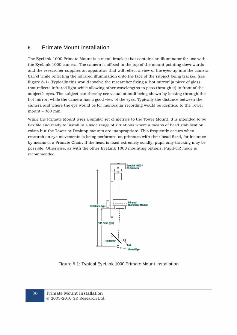
36 Primate Mount Installation 2005-2010 SR Research Ltd.
6. Primate Mount Installation
The EyeLink 1000 Primate Mount is a metal bracket that contains an illuminator for use with
the EyeLink 1000 camera. The camera is affixed to the top of the mount pointing downwards
and the researcher supplies an apparatus that will reflect a view of the eyes up into the camera
barrel while reflecting the infrared illumination onto the face of the subject being tracked (see
Figure 6-1). Typically this would involve the researcher fixing a ‘hot mirror’ (a piece of glass
that reflects infrared light while allowing other wavelengths to pass through it) in front of the
subject’s eyes. The subject can thereby see visual stimuli being shown by looking through the
hot mirror, while the camera has a good view of the eyes. Typically the distance between the
camera and where the eye would be for monocular recording would be identical to the Tower
mount – 380 mm.
While the Primate Mount uses a similar set of metrics to the Tower Mount, it is intended to be
flexible and ready to install in a wide range of situations where a means of head stabilization
exists but the Tower or Desktop mounts are inappropriate. This frequently occurs when
research on eye movements is being performed on primates with their head fixed, for instance
by means of a Primate Chair. If the head is fixed extremely solidly, pupil only tracking may be
possible. Otherwise, as with the other EyeLink 1000 mounting options, Pupil-CR mode is
recommended.
Figure 6-1: Typical EyeLink 1000 Primate Mount Installation
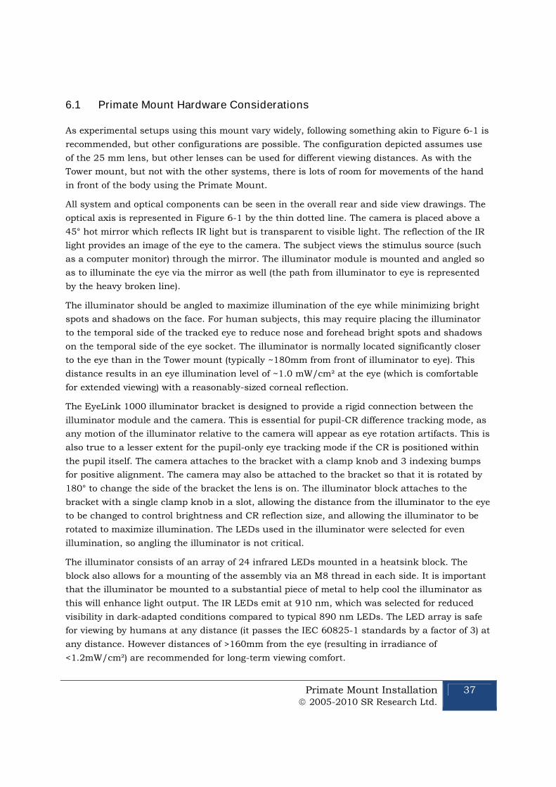
Primate Mount Installation 2005-2010 SR Research Ltd.
37
6.1 Primate Mount Hardware Considerations
As experimental setups using this mount vary widely, following something akin to Figure 6-1 is
recommended, but other configurations are possible. The configuration depicted assumes use
of the 25 mm lens, but other lenses can be used for different viewing distances. As with the
Tower mount, but not with the other systems, there is lots of room for movements of the hand
in front of the body using the Primate Mount.
All system and optical components can be seen in the overall rear and side view drawings. The
optical axis is represented in Figure 6-1 by the thin dotted line. The camera is placed above a
45° hot mirror which reflects IR light but is transparent to visible light. The reflection of the IR
light provides an image of the eye to the camera. The subject views the stimulus source (such
as a computer monitor) through the mirror. The illuminator module is mounted and angled so
as to illuminate the eye via the mirror as well (the path from illuminator to eye is represented
by the heavy broken line).
The illuminator should be angled to maximize illumination of the eye while minimizing bright
spots and shadows on the face. For human subjects, this may require placing the illuminator
to the temporal side of the tracked eye to reduce nose and forehead bright spots and shadows
on the temporal side of the eye socket. The illuminator is normally located significantly closer
to the eye than in the Tower mount (typically ~180mm from front of illuminator to eye). This
distance results in an eye illumination level of ~1.0 mW/cm² at the eye (which is comfortable
for extended viewing) with a reasonably-sized corneal reflection.
The EyeLink 1000 illuminator bracket is designed to provide a rigid connection between the
illuminator module and the camera. This is essential for pupil-CR difference tracking mode, as
any motion of the illuminator relative to the camera will appear as eye rotation artifacts. This is
also true to a lesser extent for the pupil-only eye tracking mode if the CR is positioned within
the pupil itself. The camera attaches to the bracket with a clamp knob and 3 indexing bumps
for positive alignment. The camera may also be attached to the bracket so that it is rotated by
180° to change the side of the bracket the lens is on. The illuminator block attaches to the
bracket with a single clamp knob in a slot, allowing the distance from the illuminator to the eye
to be changed to control brightness and CR reflection size, and allowing the illuminator to be
rotated to maximize illumination. The LEDs used in the illuminator were selected for even
illumination, so angling the illuminator is not critical.
The illuminator consists of an array of 24 infrared LEDs mounted in a heatsink block. The
block also allows for a mounting of the assembly via an M8 thread in each side. It is important
that the illuminator be mounted to a substantial piece of metal to help cool the illuminator as
this will enhance light output. The IR LEDs emit at 910 nm, which was selected for reduced
visibility in dark-adapted conditions compared to typical 890 nm LEDs. The LED array is safe
for viewing by humans at any distance (it passes the IEC 60825-1 standards by a factor of 3) at
any distance. However distances of >160mm from the eye (resulting in irradiance of
<1.2mW/cm²) are recommended for long-term viewing comfort.

38 Primate Mount Installation 2005-2010 SR Research Ltd.
The camera (either the Standard EyeLink 1000 Camera or the Fiber Optic Camera) mounts to
the top of the bracket using a clamp knob (M8 thread) and a set of dimples on its front. This
ensures that the camera cannot vibrate independently of the illuminator. The camera also has
5 mounting holes on its sides: 2 near the center of the camera’s sides, and 3 aligned with the
optical center of the lens and sensor. These holes take a standard 1/4”-20 screw (used on
tripod and camera mounts). However, the hole at the lens end of the camera may not be robust
enough to mount the camera with the illuminator bracket attached, especially if vibration is
present.
It is recommended that the illuminator bracket be mounted to the head restraint assembly
using the 3 holes supplied near the camera mount. The long side of the bracket should be
oriented away from the subject to maximize head clearance. Once the bracket is mounted, the
illuminator and camera may be attached and re-oriented as required. The camera may be
installed with the lens on the left or right side of the bracket, and the illuminator fitted as
required to place the connector on the side opposite the camera lens. The EyeLink
configuration files may be modified to flip the camera image as required to match any mirrors
or orientation of the camera.
While the camera will accept most C-mount lenses, the performance of most lenses is rather
poor in infrared, with blurry or dark images resulting from lens coatings or non-optimal design.
The Standard Camera configuration uses a 25 mm focal length lens, selected for high
resolution and excellent IR performance. A similar 16 mm focal length lens is available which
will allow the camera to function properly when closer to the eye.
As with other EyeLink 1000 mounting options, the camera requires 12V power, and a supplied
60 mm (24”) cable is connected from the camera to power the illuminator module. A supplied
ferrite choke on this cable must be on the end near the camera. Finally, a high-speed camera
cable is connected from the back of the camera to the tracker Host PC.
To summarize the above points, when installing the primate system please keep the following
points in mind:
The camera should not be too close to the eye, as the pupil and corneal reflection must
be contained within the tracking window.
Bringing the illuminator closer to the eye will reduce noise but may cause discomfort
and increase pupil erosion by the corneal reflection.
Placing the illuminator too far from the eye will result in a dark image and noisy data.
The line from the illuminator to the eye should be at least 10° off axis from the camera
lens for proper imaging.
The illuminator should be attached to a robust metal support, as should the camera.
Preventing separate motion of the camera and illuminator due to vibration is critical to
prevent extraneous noise in the data. The metal will also help to keep the illuminator
cool, increasing its light output.

Primate Mount Installation 2005-2010 SR Research Ltd.
39
While it is possible to rotate the camera by 90°, this will swap X and Y pupil position
data. Contact SR Research for information about operating in this configuration.
It is possible that an extra bright reflection may appear above the pupil in the eye
image, as the illuminator may directly light the eye as well as through the mirror. A
small baffle may be required to control this.
Continue to Chapter 8 “Testing the Host PC Installation”
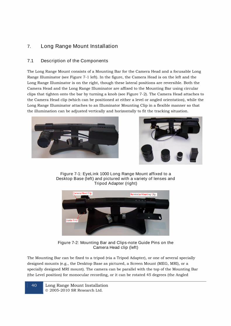
40 Long Range Mount Installation 2005-2010 SR Research Ltd.
7. Long Range Mount Installation
7.1 Description of the Components
The Long Range Mount consists of a Mounting Bar for the Camera Head and a focusable Long
Range Illuminator (see Figure 7-1 left). In the figure, the Camera Head is on the left and the
Long Range Illuminator is on the right, though these lateral positions are reversible. Both the
Camera Head and the Long Range Illuminator are affixed to the Mounting Bar using circular
clips that tighten onto the bar by turning a knob (see Figure 7-2). The Camera Head attaches to
the Camera Head clip (which can be positioned at either a level or angled orientation), while the
Long Range Illuminator attaches to an Illuminator Mounting Clip in a flexible manner so that
the illumination can be adjusted vertically and horizontally to fit the tracking situation.
Figure 7-1: EyeLink 1000 Long Range Mount affixed to aDesktop Base (left) and pictured with a variety of lenses and
Tripod Adapter (right)
Figure 7-2: Mounting Bar and Clips-note Guide Pins on theCamera Head clip (left)
The Mounting Bar can be fixed to a tripod (via a Tripod Adapter), or one of several specially
designed mounts (e.g., the Desktop Base as pictured, a Screen Mount (MEG, MRI), or a
specially designed MRI mount). The camera can be parallel with the top of the Mounting Bar
(the Level position) for monocular recording, or it can be rotated 45 degrees (the Angled

Long Range Mount Installation 2005-2010 SR Research Ltd.
41
position) for binocular (or monocular) recording. In addition to being tilted up or down, the
Illuminator can be swiveled around its vertical axis to assist with positioning. Several lenses
are available for optimal tracking at different eye-to-camera distances. Three lenses (75, 50 and
35 mm) and a tripod adapter are pictured (see Figure 7-1 right).
The most important step in setting up the mount is to align the
illuminator so that it is maximally illuminating the camera’s view.
Doing this alignment ensures that no matter where the camera is
pointed, it’s target will be lit with infrared light as long as there are no
obstacles in the way.
7.2 Overview of Setting the Mount
The most important step in setting up the long range mount is to align the illuminator so that
it maximally illuminates the location that the camera is pointing. Once this is done, the
Camera Head and Illuminator are tightened in place and the entire Mounting Bar can be easily
positioned using the ball joint on the Mount or the lever of the tripod to which it is affixed.
Aligning the Camera Head and Illuminator ensures that no matter where the camera is
pointed, its target will be lit with infrared light without requiring time-consuming adjustment of
the components.
Loosening the knob on the back of the Illuminator clip allows heading position and tilt of the
Illuminator to be adjusted. Loosening the knob on the Camera Head clip allows lateral
positioning of the Camera Head by sliding it along the Mounting Bar, and allows the angle of
the Camera Head to be rotated 45 degrees for binocular recording when an illuminated view of
both eyes can be acquired.
The long range mount is designed so that the side of the Illuminator and Camera Head are
interchangeable. Cables coming from the Camera Head should be directed so they can exit and
be securely fastened to avoid being crimped. Typically, the Camera Head and Illuminator are
located at opposite ends of the Mounting Bar, and the cables will emerge from the center.
For monocular recording, the typical position for the Illuminator will be on the same side of the
Mounting Bar as the eye-to-be-tracked, with the Camera Head on the opposite side. This
ordering may not be necessary, but can help in environments where blockage of the illuminator
can occur. The most important factor in positioning the Camera Head and Illuminator is that
there is an unobstructed line of sight from the camera to these components. Given these
recommendations, the configuration in Figure 7-1 depicts the ideal positioning for tracking a
participant’s right eye (left eye if viewed through a mirror as in many MRI setups).
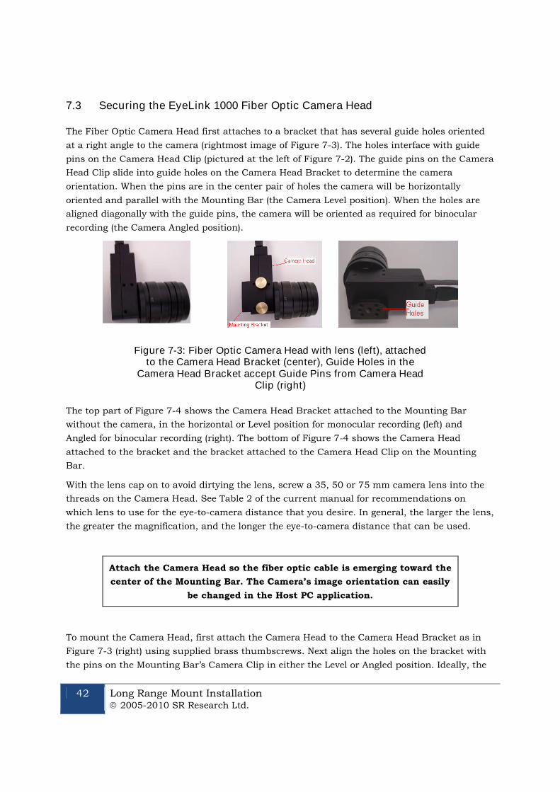
42 Long Range Mount Installation 2005-2010 SR Research Ltd.
7.3 Securing the EyeLink 1000 Fiber Optic Camera Head
The Fiber Optic Camera Head first attaches to a bracket that has several guide holes oriented
at a right angle to the camera (rightmost image of Figure 7-3). The holes interface with guide
pins on the Camera Head Clip (pictured at the left of Figure 7-2). The guide pins on the Camera
Head Clip slide into guide holes on the Camera Head Bracket to determine the camera
orientation. When the pins are in the center pair of holes the camera will be horizontally
oriented and parallel with the Mounting Bar (the Camera Level position). When the holes are
aligned diagonally with the guide pins, the camera will be oriented as required for binocular
recording (the Camera Angled position).
Figure 7-3: Fiber Optic Camera Head with lens (left), attachedto the Camera Head Bracket (center), Guide Holes in the
Camera Head Bracket accept Guide Pins from Camera HeadClip (right)
The top part of Figure 7-4 shows the Camera Head Bracket attached to the Mounting Bar
without the camera, in the horizontal or Level position for monocular recording (left) and
Angled for binocular recording (right). The bottom of Figure 7-4 shows the Camera Head
attached to the bracket and the bracket attached to the Camera Head Clip on the Mounting
Bar.
With the lens cap on to avoid dirtying the lens, screw a 35, 50 or 75 mm camera lens into the
threads on the Camera Head. See Table 2 of the current manual for recommendations on
which lens to use for the eye-to-camera distance that you desire. In general, the larger the lens,
the greater the magnification, and the longer the eye-to-camera distance that can be used.
Attach the Camera Head so the fiber optic cable is emerging toward the
center of the Mounting Bar. The Camera’s image orientation can easily
be changed in the Host PC application.
To mount the Camera Head, first attach the Camera Head to the Camera Head Bracket as in
Figure 7-3 (right) using supplied brass thumbscrews. Next align the holes on the bracket with
the pins on the Mounting Bar’s Camera Clip in either the Level or Angled position. Ideally, the
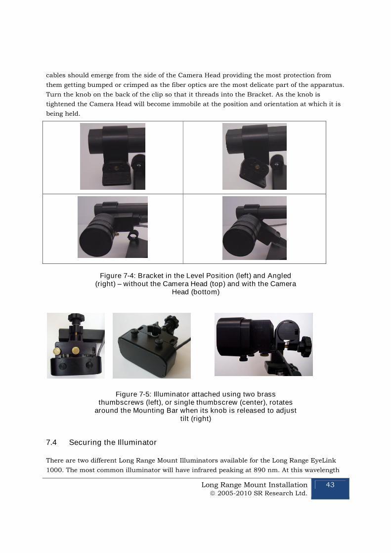
Long Range Mount Installation 2005-2010 SR Research Ltd.
43
cables should emerge from the side of the Camera Head providing the most protection from
them getting bumped or crimped as the fiber optics are the most delicate part of the apparatus.
Turn the knob on the back of the clip so that it threads into the Bracket. As the knob is
tightened the Camera Head will become immobile at the position and orientation at which it is
being held.
Figure 7-4: Bracket in the Level Position (left) and Angled(right) – without the Camera Head (top) and with the Camera
Head (bottom)
Figure 7-5: Illuminator attached using two brassthumbscrews (left), or single thumbscrew (center), rotates
around the Mounting Bar when its knob is released to adjusttilt (right)
7.4 Securing the Illuminator
There are two different Long Range Mount Illuminators available for the Long Range EyeLink
1000. The most common illuminator will have infrared peaking at 890 nm. At this wavelength
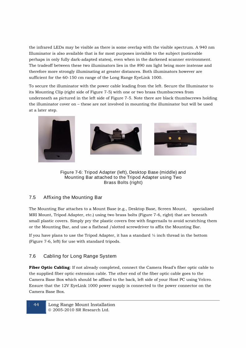
44 Long Range Mount Installation 2005-2010 SR Research Ltd.
the infrared LEDs may be visible as there is some overlap with the visible spectrum. A 940 nm
Illuminator is also available that is for most purposes invisible to the subject (noticeable
perhaps in only fully dark-adapted states), even when in the darkened scanner environment.
The tradeoff between these two illuminators lies in the 890 nm light being more instense and
therefore more strongly illuminating at greater distances. Both illuminators however are
sufficient for the 60-150 cm range of the Long Range EyeLink 1000.
To secure the illuminator with the power cable leading from the left. Secure the Illuminator to
its Mounting Clip (right side of Figure 7-5) with one or two brass thumbscrews from
underneath as pictured in the left side of Figure 7-5. Note there are black thumbscrews holding
the illuminator cover on – these are not involved in mounting the illuminator but will be used
at a later step.
Figure 7-6: Tripod Adapter (left), Desktop Base (middle) andMounting Bar attached to the Tripod Adapter using Two
Brass Bolts (right)
7.5 Affixing the Mounting Bar
The Mounting Bar attaches to a Mount Base (e.g., Desktop Base, Screen Mount, specialized
MRI Mount, Tripod Adapter, etc.) using two brass bolts (Figure 7-6, right) that are beneath
small plastic covers. Simply pry the plastic covers free with fingernails to avoid scratching them
or the Mounting Bar, and use a flathead /slotted screwdriver to affix the Mounting Bar.
If you have plans to use the Tripod Adapter, it has a standard ¼ inch thread in the bottom
(Figure 7-6, left) for use with standard tripods.
7.6 Cabling for Long Range System
Fiber Optic Cabling: If not already completed, connect the Camera Head’s fiber optic cable to
the supplied fiber optic extension cable. The other end of the fiber optic cable goes to the
Camera Base Box which should be affixed to the back, left side of your Host PC using Velcro.
Ensure that the 12V EyeLink 1000 power supply is connected to the power connector on the
Camera Base Box.
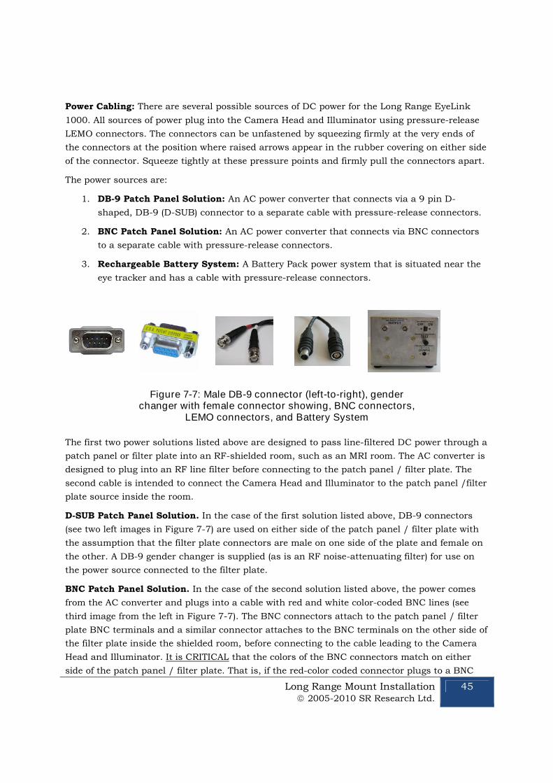
Long Range Mount Installation 2005-2010 SR Research Ltd.
45
Power Cabling: There are several possible sources of DC power for the Long Range EyeLink
1000. All sources of power plug into the Camera Head and Illuminator using pressure-release
LEMO connectors. The connectors can be unfastened by squeezing firmly at the very ends of
the connectors at the position where raised arrows appear in the rubber covering on either side
of the connector. Squeeze tightly at these pressure points and firmly pull the connectors apart.
The power sources are:
1. DB-9 Patch Panel Solution: An AC power converter that connects via a 9 pin D-
shaped, DB-9 (D-SUB) connector to a separate cable with pressure-release connectors.
2. BNC Patch Panel Solution: An AC power converter that connects via BNC connectors
to a separate cable with pressure-release connectors.
3. Rechargeable Battery System: A Battery Pack power system that is situated near the
eye tracker and has a cable with pressure-release connectors.
Figure 7-7: Male DB-9 connector (left-to-right), genderchanger with female connector showing, BNC connectors,
LEMO connectors, and Battery System
The first two power solutions listed above are designed to pass line-filtered DC power through a
patch panel or filter plate into an RF-shielded room, such as an MRI room. The AC converter is
designed to plug into an RF line filter before connecting to the patch panel / filter plate. The
second cable is intended to connect the Camera Head and Illuminator to the patch panel /filter
plate source inside the room.
D-SUB Patch Panel Solution. In the case of the first solution listed above, DB-9 connectors
(see two left images in Figure 7-7) are used on either side of the patch panel / filter plate with
the assumption that the filter plate connectors are male on one side of the plate and female on
the other. A DB-9 gender changer is supplied (as is an RF noise-attenuating filter) for use on
the power source connected to the filter plate.
BNC Patch Panel Solution. In the case of the second solution listed above, the power comes
from the AC converter and plugs into a cable with red and white color-coded BNC lines (see
third image from the left in Figure 7-7). The BNC connectors attach to the patch panel / filter
plate BNC terminals and a similar connector attaches to the BNC terminals on the other side of
the filter plate inside the shielded room, before connecting to the cable leading to the Camera
Head and Illuminator. It is CRITICAL that the colors of the BNC connectors match on either
side of the patch panel / filter plate. That is, if the red-color coded connector plugs to a BNC
46 Long Range Mount Installation 2005-2010 SR Research Ltd.
terminal on one side of the plate it MUST connect to the red-coded connector of the cable on
the other side of the plate. Failing to match these color codes will reverse positive and negative
charges and will harm the eye tracker.
Rechargeable Battery System. The third power solution listed above involves a rechargeable
battery pack (see rightmost image of Figure 7-7) located near the Camera Head and
Illuminator. A simple cable with pressure-release connectors on either end connects the battery
output to the Camera Head and Illuminator. See the User Manual for detailed battery use and
maintenance information.
7.7 Long Range Camera Setup
Follow these steps to set up the camera and illuminator for Long Range tracking. The intent is
that these steps should only have to be done once to use the Camera and Illuminator in a given
configuration. After initial set-up, multiple subjects can be run under identical conditions (e.g.,
tracking the right eye at a particular distance) requiring only minor focusing or positioning
from subject to subject.
This section is intended to be a general overview of the steps involved for ANY mount. As such
it is more general than may be desired for particular installations such as for MEG or MRI.
Readers interested in a more specific solution for particular MEG or MRI hardware may wish to
skip ahead to Section 7.8 for MEG or Section 7.9 for MRI mounts.
7.7.1 Acquire Preliminary Measurements
The first few steps in setting up the Long Range Camera require knowing the eye-to-camera
distance, which is measured from where the lens meets the Camera Head to the bridge of the
participant’s nose, in centimeters. This is the length of the entire optical path that light will
travel from the camera to the eye.
While measuring distances, also be sure to measure the distance from the eye to the screen top
and bottom, as well as the length and width of the projected image. This time the measurement
is in millimeters. Use these values to follow “Section 8.4 Customizing Your PHYSICAL.INI
Settings” to modify the PHYSICAL.INI file settings on your Host PC. This is important to ensure
correct reporting of information presented in terms of degrees of visual angle.
7.7.2 Assemble the Long Range Mount Components
1) Position the Camera Head and Illuminator. If there are no obstructions in the line of
sight from the Camera Head or Illuminator to the eye-to-be-tracked then the side of
the Mounting Bar for these items is not critically important, though having the
Illuminator on the same side as the tracked eye (Camera Head more centrally
located) may result in better illumination for monocular tracking .
Decide on the side of the Mounting Bar to place the Camera Head and Illuminator
and slip them into position, ensuring the cabling for the Camera Head is emerging
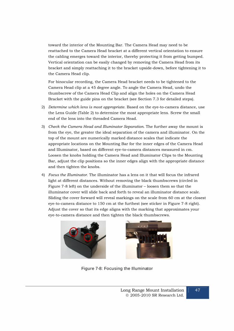
Long Range Mount Installation 2005-2010 SR Research Ltd.
47
toward the interior of the Mounting Bar. The Camera Head may need to be
reattached to the Camera Head bracket at a different vertical orientation to ensure
the cabling emerges toward the interior, thereby protecting it from getting bumped.
Vertical orientation can be easily changed by removing the Camera Head from its
bracket and simply reattaching it to the bracket upside-down, before tightening it to
the Camera Head clip.
For binocular recording, the Camera Head bracket needs to be tightened to the
Camera Head clip at a 45 degree angle. To angle the Camera Head, undo the
thumbscrew of the Camera Head Clip and align the holes on the Camera Head
Bracket with the guide pins on the bracket (see Section 7.3 for detailed steps).
2) Determine which lens is most appropriate. Based on the eye-to-camera distance, use
the Lens Guide (Table 2) to determine the most appropriate lens. Screw the small
end of the lens into the threaded Camera Head.
3) Check the Camera Head and Illuminator Separation. The further away the mount is
from the eye, the greater the ideal separation of the camera and illuminator. On the
top of the mount are numerically marked distance scales that indicate the
appropriate locations on the Mounting Bar for the inner edges of the Camera Head
and Illuminator, based on different eye-to-camera distances measured in cm.
Loosen the knobs holding the Camera Head and Illuminator Clips to the Mounting
Bar, adjust the clip positions so the inner edges align with the appropriate distance
and then tighten the knobs.
4) Focus the Illuminator. The illuminator has a lens on it that will focus the infrared
light at different distances. Without removing the black thumbscrews (circled in
Figure 7-8 left) on the underside of the illuminator – loosen them so that the
illuminator cover will slide back and forth to reveal an illuminator distance scale.
Sliding the cover forward will reveal markings on the scale from 60 cm at the closest
eye-to-camera distance to 150 cm at the furthest (see sticker in Figure 7-8 right).
Adjust the cover so that its edge aligns with the marking that approximates your
eye-to-camera distance and then tighten the black thumbscrews.
Figure 7-8: Focusing the Illuminator

48 Long Range Mount Installation 2005-2010 SR Research Ltd.
7.7.3 Align the Camera Head and Illuminator
5) Check Host Software Configuration. Start the EyeLink Host PC application and click
“Set Options” button. Check that the “Configuration” is set to “Long Range Mount
(Monocular)” or “Long Range Mount (Monoc/Binoc)” corresponding to how you
oriented the Camera Head (Level or Angled respectively for monocular and binocular
recording). Then navigate to the “Camera Setup” screen.
The next steps are often more easily accomplished if you have a large view of what
the camera is registering, The EyeLink 1000 API has the ability to transfer the global
view of the camera to the Display PC and all of the demo programs installed with the
EyeLink Developer’s Kit are capable of achieving this step (e.g., TRACK.EXE on
Windows or GCWindow.app on MacOS). After running one of the SR Research demo
programs, transfer the global camera image. For more details on this step, novice
users may wish to consult the tutorial of the EyeLink 1000 User Manual.
6) Focus the Camera and Roughly Focus the Lens. As humans do not see infrared,
monitoring the output of the infrared camera is necessary. In this step, we will shine
the Illuminator at a Target Screen (or even a wall) at the distance where the
participant’s eye(s) will eventually be and ensure that the camera’s view is centered
within the bounds of the illuminated area. The Target Screen appears at the end of
this chapter.
Start by placing the mount at the distance of the eye-to-be-tracked from the Target
Screen or a wall. With a good view of the camera’s global image on the Host or
Display PC, point the Camera Head at the Target Screen’s center (e.g., Figure 7-9).
While watching the global image, turn the lens wheel so that the image becomes
clearer – it does not have to be perfectly focused at this stage and may look
something like either image of Figure 7-9.
The following steps ensure proper illumination of whatever the camera points
at. This is done by aiming and securing the Illuminator so that the halo it
produces is in the center of the camera’s view. Because the Camera Head and
Illuminator will move together, whatever is viewed will be well-lit.
A Target Screen appears at the end of this chapter. Place the Target Screen at
the distance of the eye-to-be-tracked. It may be easiest to place the Target
Screen against a wall and to temporarily move the mount the appropriate
viewing distance for the next few steps, putting the mount into the final
location once the steps are complete.
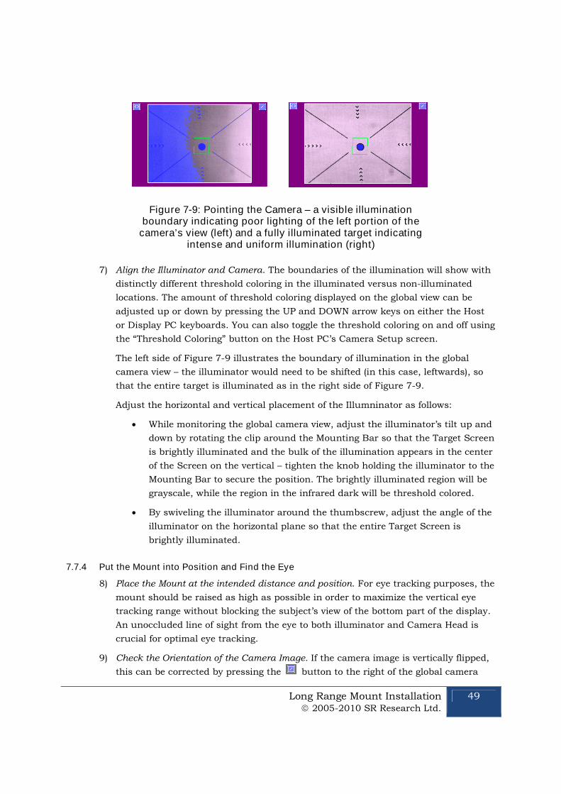
Long Range Mount Installation 2005-2010 SR Research Ltd.
49
Figure 7-9: Pointing the Camera – a visible illuminationboundary indicating poor lighting of the left portion of the
camera’s view (left) and a fully illuminated target indicatingintense and uniform illumination (right)
7) Align the Illuminator and Camera. The boundaries of the illumination will show with
distinctly different threshold coloring in the illuminated versus non-illuminated
locations. The amount of threshold coloring displayed on the global view can be
adjusted up or down by pressing the UP and DOWN arrow keys on either the Host
or Display PC keyboards. You can also toggle the threshold coloring on and off using
the “Threshold Coloring” button on the Host PC’s Camera Setup screen.
The left side of Figure 7-9 illustrates the boundary of illumination in the global
camera view – the illuminator would need to be shifted (in this case, leftwards), so
that the entire target is illuminated as in the right side of Figure 7-9.
Adjust the horizontal and vertical placement of the Illumninator as follows:
While monitoring the global camera view, adjust the illuminator’s tilt up and
down by rotating the clip around the Mounting Bar so that the Target Screen
is brightly illuminated and the bulk of the illumination appears in the center
of the Screen on the vertical – tighten the knob holding the illuminator to the
Mounting Bar to secure the position. The brightly illuminated region will be
grayscale, while the region in the infrared dark will be threshold colored.
By swiveling the illuminator around the thumbscrew, adjust the angle of the
illuminator on the horizontal plane so that the entire Target Screen is
brightly illuminated.
7.7.4 Put the Mount into Position and Find the Eye
8) Place the Mount at the intended distance and position. For eye tracking purposes, the
mount should be raised as high as possible in order to maximize the vertical eye
tracking range without blocking the subject’s view of the bottom part of the display.
An unoccluded line of sight from the eye to both illuminator and Camera Head is
crucial for optimal eye tracking.
9) Check the Orientation of the Camera Image. If the camera image is vertically flipped,
this can be corrected by pressing the button to the right of the global camera
50 Long Range Mount Installation 2005-2010 SR Research Ltd.
view on the Host PC. If the camera image is horizontally flipped, this can be
corrected by pressing the button on the left to rotate the camera image 180° and
then click on the vertical flip button.
Recommendation: Turn USE SEARCH LIMITS off and ONLY have one
eye in the camera’s view.
The EyeLink 1000 has the ability to track the eye no matter where it
falls in the camera’s view. This is highly desirable when the eye is
difficult to locate (i.e., at long distances!) and SEARCH LIMITS restricts
the area that can automatically track the eye.
10) Select the Eye to Track and Adjust Thresholds. Press the ‘A’ key for autothreshold, or
in the global camera view move the mouse cursor on top of the pupil position and
click the left mouse button. The camera image for the eye should now be displayed
in the zoomed thumbnail view. If the pupil is detected, a green box and crosshairs
will also be drawn.
Use the left or right cursor key to select the zoomed camera view. Adjust the camera
focus by turning the focusing ring of the lens. You may do the adjustment from the
side opposite to the illuminator to prevent the camera image or the illumination to
the eye from being blocked. Look closely at the eye image on the zoomed view while
turning the focusing ring until the eye image is clear. If a colored circle (CR signal)
appears near the pupil, the best focus will minimize the size of this circle.
The system is now ready to test. Please see the tutorial in the User Manual, though you may
wish to skim the contents of Chapter 8 first.
7.8 Installation in a MEG Room
The Long Range EyeLink 1000 is non-ferromagnetically optimized, made mostly of plastic,
aluminum and brass. The Fiber Optic Camera and Long Range Illuminator minimize electrical
noise and attach to the Mounting Bar using brass thumbscrews, plastic clips and aluminum
brackets. All of these features, coupled with excellent shielding, make the system ideal for a
MEG environment.
The Camera Head, Illuminator and Mount are located inside the MEG room, with DC power
entering the room through a waveguide along with a fiber optic cable, or with a rechargeable
battery system contained within the room to eliminate the need for cables to enter. Typically an
AC power supply is located outside the room and plugged into an isolated source as even this
inexpensive solution produces low noise. The Host PC too is situated outside of the MEG room,
though the camera images can be transferred and projected into the room via an application
running on the Display PC, making camera setup easily accomplished. As the only connection
between the room and the Host PC is fiber optic, no other isolated power outlets are required.
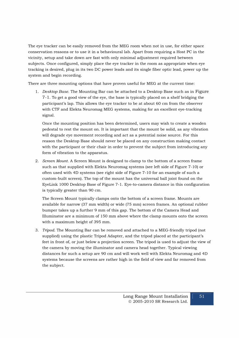
Long Range Mount Installation 2005-2010 SR Research Ltd.
51
The eye tracker can be easily removed from the MEG room when not in use, for either space
conservation reasons or to use it in a behavioural lab. Apart from requiring a Host PC in the
vicinity, setup and take down are fast with only minimal adjustment required between
subjects. Once configured, simply place the eye tracker in the room as appropriate when eye
tracking is desired, plug in its two DC power leads and its single fiber optic lead, power up the
system and begin recording.
There are three mounting options that have proven useful for MEG at the current time:
1. Desktop Base. The Mounting Bar can be attached to a Desktop Base such as in Figure
7-1. To get a good view of the eye, the base is typically placed on a shelf bridging the
participant’s lap. This allows the eye tracker to be at about 60 cm from the observer
with CTF and Elekta Neuromag MEG systems, making for an excellent eye-tracking
signal.
Once the mounting position has been determined, users may wish to create a wooden
pedestal to rest the mount on. It is important that the mount be solid, as any vibration
will degrade eye movement recording and act as a potential noise source. For this
reason the Desktop Base should never be placed on any construction making contact
with the participant or their chair in order to prevent the subject from introducing any
form of vibration to the apparatus.
2. Screen Mount. A Screen Mount is designed to clamp to the bottom of a screen frame
such as that supplied with Elekta Neuromag systems (see left side of Figure 7-10) or
often used with 4D systems (see right side of Figure 7-10 for an example of such a
custom-built screen). The top of the mount has the universal ball joint found on the
EyeLink 1000 Desktop Base of Figure 7-1. Eye-to-camera distance in this configuration
is typically greater than 90 cm.
The Screen Mount typically clamps onto the bottom of a screen frame. Mounts are
available for narrow (37 mm width) or wide (75 mm) screen frames. An optional rubber
bumper takes up a further 9 mm of this gap. The bottom of the Camera Head and
Illuminator are a minimum of 150 mm above where the clamp mounts onto the screen
with a maximum height of 395 mm.
3. Tripod. The Mounting Bar can be removed and attached to a MEG-friendly tripod (not
supplied) using the plastic Tripod Adapter, and the tripod placed at the participant’s
feet in front of, or just below a projection screen. The tripod is used to adjust the view of
the camera by moving the illuminator and camera head together. Typical viewing
distances for such a setup are 90 cm and will work well with Elekta Neuromag and 4D
systems because the screens are rather high in the field of view and far removed from
the subject.
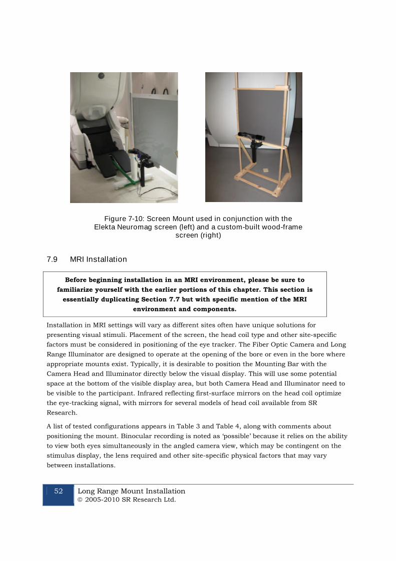
52 Long Range Mount Installation 2005-2010 SR Research Ltd.
Figure 7-10: Screen Mount used in conjunction with theElekta Neuromag screen (left) and a custom-built wood-frame
screen (right)
7.9 MRI Installation
Before beginning installation in an MRI environment, please be sure to
familiarize yourself with the earlier portions of this chapter. This section is
essentially duplicating Section 7.7 but with specific mention of the MRI
environment and components.
Installation in MRI settings will vary as different sites often have unique solutions for
presenting visual stimuli. Placement of the screen, the head coil type and other site-specific
factors must be considered in positioning of the eye tracker. The Fiber Optic Camera and Long
Range Illuminator are designed to operate at the opening of the bore or even in the bore where
appropriate mounts exist. Typically, it is desirable to position the Mounting Bar with the
Camera Head and Illuminator directly below the visual display. This will use some potential
space at the bottom of the visible display area, but both Camera Head and Illuminator need to
be visible to the participant. Infrared reflecting first-surface mirrors on the head coil optimize
the eye-tracking signal, with mirrors for several models of head coil available from SR
Research.
A list of tested configurations appears in Table 3 and Table 4, along with comments about
positioning the mount. Binocular recording is noted as ‘possible’ because it relies on the ability
to view both eyes simultaneously in the angled camera view, which may be contingent on the
stimulus display, the lens required and other site-specific physical factors that may vary
between installations.
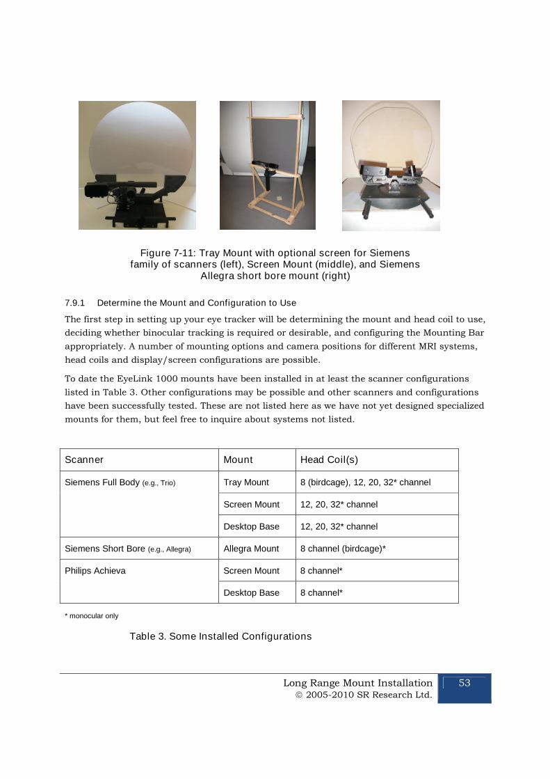
Long Range Mount Installation 2005-2010 SR Research Ltd.
53
Figure 7-11: Tray Mount with optional screen for Siemensfamily of scanners (left), Screen Mount (middle), and Siemens
Allegra short bore mount (right)
7.9.1 Determine the Mount and Configuration to Use
The first step in setting up your eye tracker will be determining the mount and head coil to use,
deciding whether binocular tracking is required or desirable, and configuring the Mounting Bar
appropriately. A number of mounting options and camera positions for different MRI systems,
head coils and display/screen configurations are possible.
To date the EyeLink 1000 mounts have been installed in at least the scanner configurations
listed in Table 3. Other configurations may be possible and other scanners and configurations
have been successfully tested. These are not listed here as we have not yet designed specialized
mounts for them, but feel free to inquire about systems not listed.
Scanner Mount Head Coil(s)
Siemens Full Body (e.g., Trio) Tray Mount 8 (birdcage), 12, 20, 32* channel
Screen Mount 12, 20, 32* channel
Desktop Base 12, 20, 32* channel
Siemens Short Bore (e.g., Allegra) Allegra Mount 8 channel (birdcage)*
Philips Achieva Screen Mount 8 channel*
Desktop Base 8 channel*
* monocular only
Table 3. Some Installed Configurations
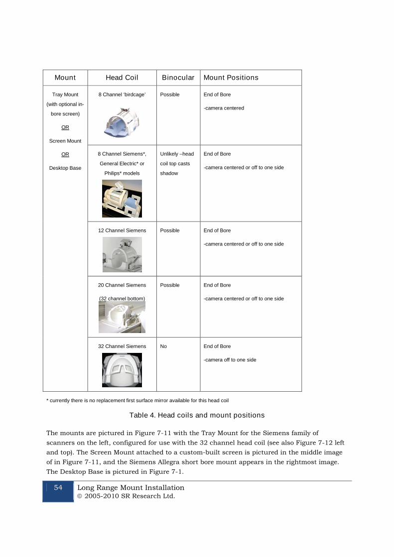
54 Long Range Mount Installation 2005-2010 SR Research Ltd.
Mount Head Coil Binocular Mount Positions
Tray Mount
(with optional in-
bore screen)
OR
Screen Mount
OR
Desktop Base
8 Channel ‘birdcage’ Possible End of Bore
-camera centered
8 Channel Siemens*,
General Electric* or
Philips* models
Unlikely –head
coil top casts
shadow
End of Bore
-camera centered or off to one side
12 Channel Siemens Possible End of Bore
-camera centered or off to one side
20 Channel Siemens
(32 channel bottom)
Possible End of Bore
-camera centered or off to one side
32 Channel Siemens No End of Bore
-camera off to one side
* currently there is no replacement first surface mirror available for this head coil
Table 4. Head coils and mount positions
The mounts are pictured in Figure 7-11 with the Tray Mount for the Siemens family of
scanners on the left, configured for use with the 32 channel head coil (see also Figure 7-12 left
and top). The Screen Mount attached to a custom-built screen is pictured in the middle image
of in Figure 7-11, and the Siemens Allegra short bore mount appears in the rightmost image.
The Desktop Base is pictured in Figure 7-1.
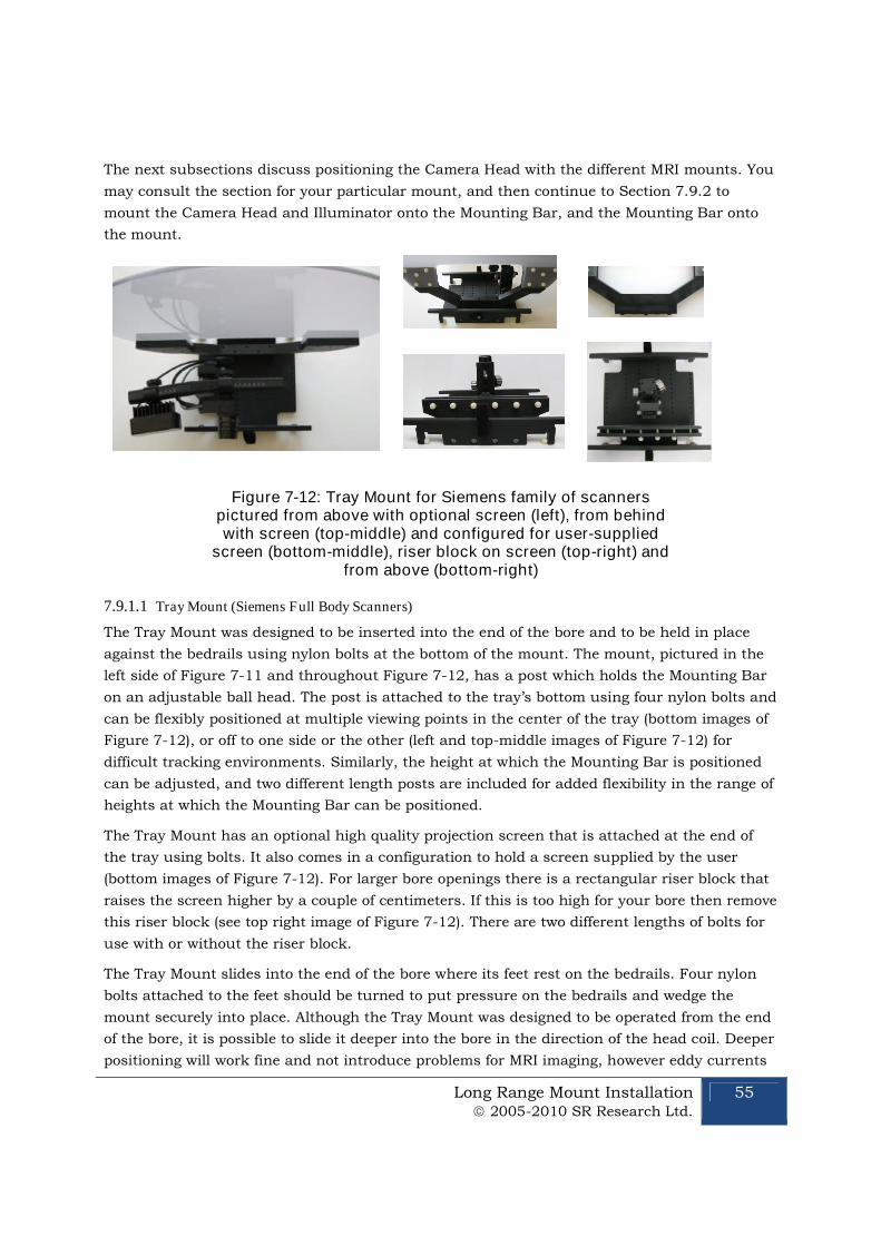
Long Range Mount Installation 2005-2010 SR Research Ltd.
55
The next subsections discuss positioning the Camera Head with the different MRI mounts. You
may consult the section for your particular mount, and then continue to Section 7.9.2 to
mount the Camera Head and Illuminator onto the Mounting Bar, and the Mounting Bar onto
the mount.
Figure 7-12: Tray Mount for Siemens family of scannerspictured from above with optional screen (left), from behindwith screen (top-middle) and configured for user-supplied
screen (bottom-middle), riser block on screen (top-right) andfrom above (bottom-right)
7.9.1.1 Tray Mount (Siemens Full Body Scanners)
The Tray Mount was designed to be inserted into the end of the bore and to be held in place
against the bedrails using nylon bolts at the bottom of the mount. The mount, pictured in the
left side of Figure 7-11 and throughout Figure 7-12, has a post which holds the Mounting Bar
on an adjustable ball head. The post is attached to the tray’s bottom using four nylon bolts and
can be flexibly positioned at multiple viewing points in the center of the tray (bottom images of
Figure 7-12), or off to one side or the other (left and top-middle images of Figure 7-12) for
difficult tracking environments. Similarly, the height at which the Mounting Bar is positioned
can be adjusted, and two different length posts are included for added flexibility in the range of
heights at which the Mounting Bar can be positioned.
The Tray Mount has an optional high quality projection screen that is attached at the end of
the tray using bolts. It also comes in a configuration to hold a screen supplied by the user
(bottom images of Figure 7-12). For larger bore openings there is a rectangular riser block that
raises the screen higher by a couple of centimeters. If this is too high for your bore then remove
this riser block (see top right image of Figure 7-12). There are two different lengths of bolts for
use with or without the riser block.
The Tray Mount slides into the end of the bore where its feet rest on the bedrails. Four nylon
bolts attached to the feet should be turned to put pressure on the bedrails and wedge the
mount securely into place. Although the Tray Mount was designed to be operated from the end
of the bore, it is possible to slide it deeper into the bore in the direction of the head coil. Deeper
positioning will work fine and not introduce problems for MRI imaging, however eddy currents
56 Long Range Mount Installation 2005-2010 SR Research Ltd.
from the magnetic field will introduce greater vibrations in the eye movement recordings. For
this reason it is recommended to position the Tray Mount at the end of the bore.
The Tray Mount has a hole cut out beneath the screen so that the operator can reach in to
adjust the position of the Mounting Bar and focus the lens. It is expected that during Camera
Setup and calibration, the image from the camera will be projected onto the screen (either the
optional Tray Mount screen or the screen provided by the user) so that the effects of the
operator’s adjustments can be monitored.
For binocular recording, the post holding the Mounting Bar should be centered as pictured in
the bottom right images of Figure 7-12.
Use with the Siemen’s 32 Channel Head Coil. For use with the 32 channel Siemens head
coil (monocular only) the post needs to be displaced to the side of the eye-to-be-tracked. The
mounts in the left image in Figure 7-11 and also Figure 7-12 left and top are all configured for
tracking a subject’s right eye if used with the 32 channel Siemen’s head coil.
Note that placement of the illuminator is as peripheral as possible and that the Camera Head is
as far toward the center of the Mounting Bar as possible. This may shift the placement of these
components from the recommend positions on the scale, but they remain separated and
importantly, have a more lateral view of the eye through the mask of the head coil. It is feasible
that both the Illuminator and Camera Head be placed on the same side of the Mounting Bar to
make the camera view slightly more peripheral.
To optimize the eye tracking the subject’s head should be elevated as high as possible without
touching the mask of the head coil. For optimal brain imaging, ensure that the head remains
centered in the head coil – padding one side of the head so it is held more laterally will result in
better eye tracking but may produce inferior brain images.
7.9.1.2 Screen Mount (all scanner types)
The Screen Mount is designed to clamp to the bottom of a user-supplied screen that is situated
outside and at the end of the bore. Once clamped onto the bottom of the screen frame, the
height of a ball head holding the Mounting Bar can be adjusted to provide the optimal view of
the eye in the head coil mirror. Loosening the knob of the Screen Mount allows the component
holding the Mounting bar to slide up and down. The optimal Mounting Bar position from an
eye-tracking stance is as high in the field of view as possible, without blocking the bottom of
the display.
There are two Screen Mount configurations. The mounts are available for narrow (37 mm
width) or wide (75 mm) screen frames. An optional rubber bumper takes up a further 9 mm of
this gap. The bottom of the Camera Head and Illuminator are a minimum of 150 mm above
where the clamp mounts onto the screen with a maximum height of 395 mm.
For binocular recording the Screen Mount, and hence the Mounting Bar, should be centered at
the end of the bore. For use with head coils that provide visual obstacles when viewed directly
from behind (e.g., the 32 channel Siemens head) the eye tracker will need to be displaced to the
Long Range Mount Installation 2005-2010 SR Research Ltd.
57
side of the eye-to-be-tracked. Ideally, the surface area of the projection screen should be much
larger than is required so that even with the Screen Mount attached to the center of the screen,
the screen can be slid to the side (moving the eye monitor off to the side with it) while still
allowing the entre display projection to land on the screen surface. This makes for easy
positioning of the eye tracker with the ability to switch between the eye-to-be-tracked
monocularly (such as with the Siemens 32 channel head coil) by simply moving the screen. The
alternative is to loosen the mount holding the eye tracker to the screen and physically move its
position beneath the screen.
7.9.1.3 Desktop Base (all scanner types)
The Desktop Base is simply a modified version of the Desktop Mount’s ball joint base, made
without ferromagnetic materials. It provides a quick and easy way to hold the Mounting Bar in
position for fast setup of the eye tracker. The drawback is that it may not be as easy to keep in
position between subjects as the more specialized mounts that are also fixed in position.
Though other mounts may be preferable as they are customized to particular scanner
environments, the Desktop Base is often useful as it can be used in the MRI environment and
is very amenable to testing different eye tracking configurations. Simply position the Desktop
Base with the Mounting Bar attached outside the bore on top of something sturdy with no
ferromagnetic content – such as a stool or table from within the MRI room.
For binocular recording the Desktop Base and Mounting Bar should be centered at the end of
the bore. For use with head coils that provide visual obstacles when viewed directly from
behind (e.g., the 32 channel Siemens head), the Desktop Base needs to be as far over to the
side as possible with the Mounting Bar tilted on an angle so that neither the Camera Head nor
Illuminator are blocked by the bore. The same principles apply as with the regular mounts – if
the subject has a clear line of sight to the Illuminator and the Camera Head then tracking is
possible.
7.9.1.4 Short Bore Mount (Siemen’s Allegra)
A special mount has been created for short bore scanners such as the Siemen’s Allegra that
goes into the bore. The Camera Head and Illuminator are seated on the bottom of the bore
pointed straight up at a “hot mirror”. The hot mirror reflects infrared light while passing light in
the visible spectrum, thereby allowing the subject a clear view out the back of the bore. The hot
mirror reflects the image of the eye from the head coil mirror to the Camera Head while also
reflecting the infrared from the Illuminator to light up the eye.
Given the limited space in the bore there is really only one place for the mount, though the
Camera Head and Illuminator, mounted on a dowel, can have their angle adjusted.
The Allegra Mount supports monocular eye tracking only.
7.9.2 Mounting the Camera Head and Illuminator
After determining the mount to use, it is time to begin assembling the components. Based on
the mount, head coil and whether or not to track binocularly, decide which side of the
58 Long Range Mount Installation 2005-2010 SR Research Ltd.
Mounting Bar to place the Camera Head on, and which side to place the Illuminator. The
general considerations below apply to any mount or MRI eye tracking environment.
For most purposes, placing the Camera Head on the left side of the mounting bar
when viewed from behind (right side when viewed looking into the camera is a
good position to start with. This has the camera centrally viewing the eye(s) and
the illumination off to the side.
Depending upon your tracking situation, there are a few considerations in optimal placement
of these components:
The Camera Head always needs an unobstructed line-of-sight view to the eye(s) to be
tracked.
Which eye will be tracked – the dominant eye? Left or right? Having the Camera Head
on the same side as the eye-to-be-tracked may allow one to avoid obstructions.
Is binocular tracking required? For binocular tracking a more centered camera view is
desirable.
Illuminator placement does not have to be perfect as long as there are no obstructions
causing a shadow to be cast across the eye(s) to be tracked.
The Camera Head and Illuminator can be positioned on either side of the Mounting Bar, but a
peripheral illumination source is likely to be desirable so that the camera can have a view of
the eye that is as perpendicular as possible. Having a view of both eyes will enable binocular
recording, or the easy ability to switch between recording left or right eye, something that may
not be possible when the Camera Head is more peripherally placed.
Having said this, there may be situations (e.g., the Siemens 32 channel head coil, or the 8
channel head coil used with the Siemen’s, Philips and General Electric Scanners) where more
peripheral placement of the Camera Head (hence central placement of the Illuminator, and
monocular-only recording) is necessary. For instance if the head coil is blocking the Camera
Head’s view when it is centrally positioned, then moving the Camera Head more laterally may
be necessary to acquire an unobstructed view. In such cases the eye-to-be-tracked will most
likely remain the same across all subjects to prevent having to reconfigure the mount on a
subject-by-subject basis, as this can be a more time consuming (5-10 minute) procedure.
After determining which side to place the Camera Head and Illuminator, slide these
components onto the Mounting Bar, but do not yet tighten them into place.
A second consideration regarding the Camera Head is whether it needs to be level (for
monocular tracking) or angled (for binocular tracking). See Section 7.3 for detailed steps
regarding angling the Camera Head for binocular recording.
Long Range Mount Installation 2005-2010 SR Research Ltd.
59
7.9.3 The Head Coil Mirror
The Head Coil Mirror signal needs to be clear and stable for a good eye tracking signal. A first-
surface mirror with good infrared reflecting properties is desirable. The default mirrors
provided by head coil manufacturers is typically not a first-surface mirror, resulting in extra
reflections which can interfere with the image of the pupil and CR, and typically reduces
illumination. This reduces the accuracy of the eye tracker.
SR Research strives to make available good-quality first-surface mirrors (with the silver
reflective coating on the front surface rather than the back surface, and with a high infrared
transmitting coating) for popular MRI systems. Use of such a mirror yields an improved image
signal and cuts down on the number of extra refraction artifacts that can pollute the camera
image. If building your own head coil mirror, try to ensure that a first-surface mirror is used.
Put the desired mirror on the head coil. The goal is to align the illuminator and camera with
the mirror so that reflected infrared from the illuminator lights up the eye-to-be-tracked while
the mirror reflects the image of the eye, back to the camera. To achieve this, direct line-of-sight
from the camera and illuminator via the head coil mirror is required.
7.9.3.1 Replacement First Surface Head Coil Mirrors
SR Research is currently working to replace the standard mirrors on popular systems. Due to
time-consuming and labor-intensive manufacture of these mirrors we cannot easily custom-
make mirrors. If your site uses a custom mirror that has a wider range of tilt and a larger field
of view than manufacturer-supplied head coil mirrors, you may wish to look into obtaining a
front-surface mirror with good infrared reflecting properties. The only head coil pictured in
Table 4 for which SR Research cannot currently supply a front surface replacement mirror is
the 8 channel head coil sometimes used with Siemens scanners and frequently used with the
Philips Achieva.
7.9.3.2 Minimizing Head Coil Mirror Vibration
First surface replacement mirrors typically affix to the head coil in an identical way to the
manufacturer supplied mirrors. It is important that the mirror vibrate as little as possible in
order to minimize the vibration of the stimulus display experienced by the subject and to
minimize movement of the eye image in the mirror from sources other than the eye itself.
Sometimes using thick tape where the mirror assembly contacts the head coil can result in a
tighter connection between the mirror assembly and the head coil as well as dampening the
vibration. Alternatively Velcro may help to secure the mirror in position and assist in damping
vibration.
Minimizing vibration of the head coil itself is important as this will in turn reduce vibration of
the mirror.
60 Long Range Mount Installation 2005-2010 SR Research Ltd.
7.9.4 Measuring and Using the Eye-to-Camera Distance
Before putting the eye tracker in position, measure the distance between the camera and the
head coil mirror as well as the mirror to the eye. The sum of these distances is the eye-to-
camera distance (ETCD) and will be used as discussed in Section 7.7 to:
1. Select the lens to use
The ETCD is used to select whether to use a 35 mm, 50 mm or 75 mm lens. These
operate at viewing distances of 50-90 cm, 90-120 cm and 100-150 cm respectively (see
Table 2). Affix the appropriate lens to the Camera Head by turning the threaded lens
into the Camera Head.
2. Set the lateral position of the Camera Head and Illuminator on the Mounting Bar. Use
the ETCD to set the separation between the Camera Head and Illuminator, by aligning
the edge of the Camera Head and Illuminator clips with the ETCD value marked on the
Mounting Bar scales. For more details see item number 1) in Section 7.7.2.
3. Focus the Illuminator by setting the edge of the Illuminator cover to the ETCD as
marked on the scale on the Illuminator’s top. For more details see item number 4) in
Section 7.7.2.
4. Align the Iluminator to maximally light where the Camera Head is pointed as detailed in
Section 7.7.3.
While measuring distances, also be sure to measure the eye to screen top and bottom, as well
as the width and height of the projected image. This time the measurement is in millimeters.
Use these values to follow “Section 8.4 Customizing Your PHYSICAL.INI Settings” and to modify
the PHYSICAL.INI file settings on your Host PC.
7.9.5 Align the Camera Head and Illuminator
Follow the instructions from Section 7.7.3 to align the Camera Head and the Illuminator so
that no matter where the camera is pointing it is well lit. Having performed the alignment
outside of the bore, put the eye tracker into position.
For an alternative approach to aligning the Camera Head and Illuminator with the mount in
place, see the following section.
7.9.6 Put a Volunteer/Confederate in the Scanner and Find the Eye(s)
To aid in the fine positioning of the camera and illuminator, have the Display PC projecting the
global image of the camera as you finely adjust the camera and illuminator position by moving
the Mounting Bar. Be sure it is the global image that is being projected as this will show the
entire range of the camera and make it easier to get the camera’s field of view to include the
eye.
At this point, it will be easiest to have a volunteer in the bore with the head coil and head coil
mirror in place, as though ready to be scanned. The volunteer should be able to report line of
Long Range Mount Installation 2005-2010 SR Research Ltd.
61
sight to both the Illuminator and the Camera Head when the mirror is tilted at an angle
yielding a good view of the entire area where the stimulus is to be displayed.
Adjust the focus of the lens by turning the lens barrel to roughly focus the lens so that at least
what you are looking at is clear. Use any landmarks of the head coil (such as writing) to orient
your pointing of the camera; having the volunteer make recognizable movements such as
winking might help. The threshold coloring of the Host computer may assist in finding the eye,
but keep in mind that if you would rather see the image uncolored, you can turn the coloring
off and on by toggling the “Threshold Coloring” button of the Camera Setup screen.
Adjust the Mounting Bar of the eye tracker to change the Camera Head’s view. The eye needs to
be clearly visible in the camera’s global view and ideally, not too close to the edges of the
camera’s view. If operating in monocular mode, be sure only one eye is present in the global
image. When the system is capable of tracking the eye, crosshairs will appear on the pupil and
corneal reflection indicating that the system is capable of picking up the eye.
If the observer can clearly see the infrared points of the illuminator (890 nm - the 940 nm
Illuminator may be invisible) as well as having line of sight down the barrel of the lens, then
the camera and illuminator are close to the correct position. Have the volunteer report on how
the camera should be adjusted to achieve their ability in seeing down the camera barrel. Note
that this is an alternative method to aligning the Camera Head and Illuminator – after finding
the eye in the center of the global camera image, adjust the illuminator angle so that the eye(s)
and its(their) surround are well lit.
7.9.7 Adjust Image Thresholds and Focus the Lens
This section assumes some familiarity with the basics of using the EyeLink 1000. For a
thorough introduction to a tracking session, please consult the tutorial in Section 3 of the
EyeLink 1000 User Manual. Some of the essential steps are recapped here, but for an overview
of the procedure and the reasoning behind the different steps, please consult the tutorial.
Once the eye is in view of the camera and the crosshairs are present, with threshold coloring
turned on, switch to the zoomed in thumbnail view of the eye. The thumbnail that is selected
and transferred to the Display PC can be toggled by pressing the left or right arrow/cursor keys
on either keyboard.
Focus the lens. The goal is to minimize the size of the corneal reflection, resulting a good focus
overall. Simply turn the barrel of the lens while monitoring the size of the corneal reflection to
minimize it. If threshold coloring is preventing a clear view of the eye, try ‘A’ for autothreshold
to set the thresholds in reasonable range.
Once the image is in focus, press ‘A’ on the Host or Display PC keyboard to perform an
‘autothreshold’ or use the mouse to click on the pupil of the eye, which will typically perform
an autothreshold procedure. Autothreshold simply guesses at some appropriate threshold
levels to use in determining which parts of the image belong to the pupil and the corneal
reflection. Pupil threshold levels should be above 60 (presented below the thumbnail image)
otherwise this indicates that the illumination is not good. Below a level of about 60 will

62 Long Range Mount Installation 2005-2010 SR Research Ltd.
produce noisy sample data even if the system is able to track the eye. The corneal reflection
threshold is rather robust at most threshold settings, but typically optimal recordings can be
achieved by reducing the threshold slightly to completely fill out the coloring of the corneal
reflection.
If you are running the TRACK.EXE program as recommended, press C to begin the camera
setup, calibration and validation steps. Refer to the tutorial of Section 3 of the User Manual for
more information about performing the calibration and validation under normal behavioral
laboratory situations.
7.10 Calibration and Drift Correcting with the Long Range System
There are a number of operational differences between the EyeLink 1000 between use in the
behavioral laboratory and in environments where the Long Range amount is typically installed.
The first of these issues has to do with configuring custom calibration layouts so that odd-
shaped spatial areas can be calibrated. A second issue has to do with whether and how to
employ drift correction in conjunction with the EyeLink 1000 and the Long Range Mount.
7.10.1 Calibrating Atypical Spatial Areas
7.10.1.1 Customized Calibration Target Positions
Given the confines of an MRI scanner and different screen and head coil configurations, the
standard calibration of the entire screen area may not always be appropriate. For instance, if a
display projection eliminates the ability of the subject to view the corners of the display (e.g., so
that the bottom part of the display can use more of the bore’s area to present the stimulus),
calibration targets presented in the corners will not be viewable by the subject, and the
standard calibration cannot proceed. Similar issues can arise if the head coil blocks part of the
projection screen (e.g., with the Siemens 32 channel head coil, or some 8 channel head coils).
This presents a problem if one is using the default approach of calibrating the entire screen, as
calibration targets may appear in locations that cannot be viewed by at least one of the eyes,
some of the time.
The EyeLink calibration target positions can be customized, so even if the area to calibrate is
not rectangular, targets can be delivered anywhere in an automated fashion.
Having an observer or two (with highly variable head sizes) report from in the bore on the
monocularly viewable areas of your display with each eye and map out the display coordinates
that define the viewable area. A set of custom calibration points can be generated for your
display region that distributes calibration points throughout the space that can be seen. For an
example of how to configure such a custom calibration please see the discussion on the SR
Research Support Forums: https://www.sr-support.com/forums/showthread.php?t=68.
Note that Experiment Builder’s Camera Setup node has specialized support for customized
calibration target positions and also has a facility for calibrating the eye tracker completely
Long Range Mount Installation 2005-2010 SR Research Ltd.
63
from within the scanner room if a fiber optic response device is available. Please see the
Experiment Builder online help for the “Camera Setup” action, paying particular attention to
“Customized Calibration Positions” and mention of “External Control”.
7.10.1.2 Simple Horizontal or Vertical Scaling of Target Positions
A quick and easy to implement approach for simply scaling the horizontal or vertical extent of
the calibration area is to use the calibration_area_proportion, and
validation_area_proportion commands to set the proportion of the X and Y display area to
use during calibration and validation. This can help when less than the entire display is
viewable by subjects and is much quicker than redefining all of the calibration positions as it
will scale the existing positions. Hence this approach is particularly useful when first trying to
calibrate the eye tracker in a non-standard setting.
By changing these simple commands’ X and Y values one can easily shrink the dispersion of
the points in the horizontal or vertical dimension respectively. The commands as used below
shrink to 88% of the X dimension of the display and 53% of the Y dimension of the display.
Simply include these lines in your EYELINK:\ELCL\EXE\FINAL.INI or send them over the link
as EyeLink commands from Experiment Builder or your favorite programming method. Note
that default values for this command are 0.88 for X and 0.83 for Y.
calibration_area_proportion 0.88 0.53
validation_area_proportion 0.88 0.53
7.10.2 Drift Correction
The standard configuration of the EyeLink 1000 for behavioral laboratory use comes with Drift
Correction disabled. When the EyeLink 1000 is used with the Long Range mount, small
changes in pupil size or head position can translate to larger absolute inaccuracies given the
larger eye-to-camera distances typically used. For this reason enabling drift correction may be
desirable with the Long Range mount.
The EyeLink 1000 User Manual gives detailed information about enabling Drift Correction in
several ways. Of particular interest for MEG.MRI users is online drift correction, whereby drift
correction can be undertaken while recording is underway.
Please consult Section 3.11 of the User Manual for Drift Correction options.
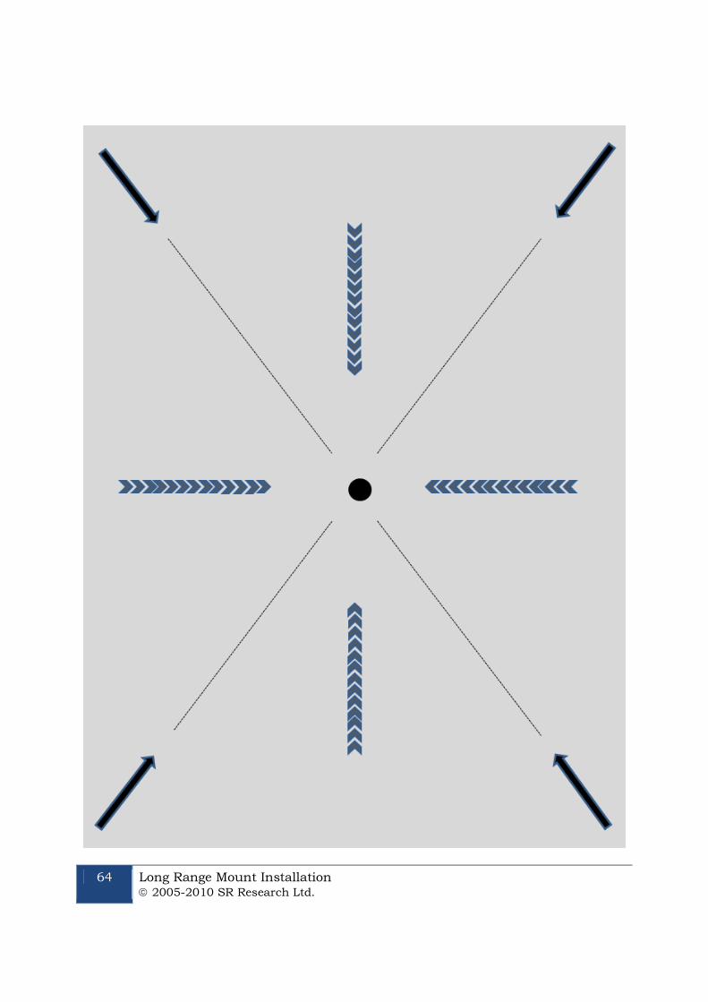
64 Long Range Mount Installation 2005-2010 SR Research Ltd.
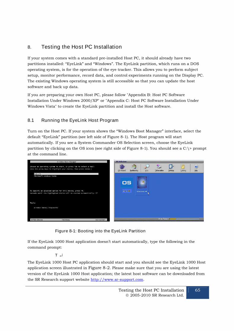
Testing the Host PC Installation 2005-2010 SR Research Ltd.
65
8. Testing the Host PC Installation
If your system comes with a standard pre-installed Host PC, it should already have two
partitions installed: “EyeLink” and “Windows”. The EyeLink partition, which runs on a DOS
operating system, is for the operation of the eye tracker. This allows you to perform subject
setup, monitor performance, record data, and control experiments running on the Display PC.
The existing Windows operating system is still accessible so that you can update the host
software and back up data.
If you are preparing your own Host PC, please follow "Appendix B: Host PC Software
Installation Under Windows 2000/XP" or "Appendix C: Host PC Software Installation Under
Windows Vista" to create the EyeLink partition and install the Host software.
8.1 Running the EyeLink Host Program
Turn on the Host PC. If your system shows the “Windows Boot Manager” interface, select the
default “EyeLink” partition (see left side of Figure 8-1). The Host program will start
automatically. If you see a System Commander OS Selection screen, choose the EyeLink
partition by clicking on the OS icon (see right side of Figure 8-1). You should see a C:\> prompt
at the command line.
Figure 8-1: Booting into the EyeLink Partition
If the EyeLink 1000 Host application doesn’t start automatically, type the following in the
command prompt:
T
The EyeLink 1000 Host PC application should start and you should see the EyeLink 1000 Host
application screen illustrated in Figure 8-2. Please make sure that you are using the latest
version of the EyeLink 1000 Host application; the latest host software can be downloaded from
the SR Research support website http://www.sr-support.com.
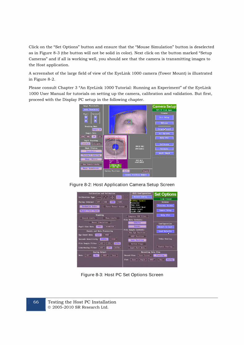
66 Testing the Host PC Installation 2005-2010 SR Research Ltd.
Click on the “Set Options” button and ensure that the “Mouse Simulation” button is deselected
as in Figure 8-3 (the button will not be solid in color). Next click on the button marked “Setup
Cameras” and if all is working well, you should see that the camera is transmitting images to
the Host application.
A screenshot of the large field of view of the EyeLink 1000 camera (Tower Mount) is illustrated
in Figure 8-2.
Please consult Chapter 3 “An EyeLink 1000 Tutorial: Running an Experiment” of the EyeLink
1000 User Manual for tutorials on setting up the camera, calibration and validation. But first,
proceed with the Display PC setup in the following chapter.
Figure 8-2: Host Application Camera Setup Screen
Figure 8-3: Host PC Set Options Screen
Testing the Host PC Installation 2005-2010 SR Research Ltd.
67
8.2 Troubleshooting Instructions
This section lists some of the error messages you may see when starting the host software.
8.2.1 SCD file does not exist
Each EyeLink 1000 system loads a camera-specific .SCD file. If you see the following error
when starting up the tracker, please ensure that “********.SCD” file is contained in the
ELCL\EXE directory.
ERROR: Camera data file ‘c:/ELCL/EXE/********.SCD’ does not exist
You can find the camera-specific .SCD file in the Host Partition \ ELCL \ EXE directory of the
EyeLink 1000 Software CD that came with your system. If you cannot locate this file, please
contact [email protected].
8.2.2 “No Hardware” error
The eye tracker reports the current network status between the Host PC and display computer.
If you see a “No Hardware” at the top-left corner of the Host Program, please check whether the
Ethernet card is properly seated.
8.2.3 EyeLink CL camera not found
Sometimes, the eye tracker will not start and the following “EyeLink CL camera not
found” error will be displayed in the command prompt.
EyeLink CL camera not found.
ERROR: EyeLink CL mode selected but hardware not operational:
Use the -x option to run in simulation mode.
This error could be caused by the following possibilities:
1) The power to the Standard Camera or Camera Base Box is not powered. Please check
the power cables and ensure the power light is glowing.
2) The camera link data cable is not properly connected to the framegrabber card or to the
camera, or the connection is loose. Try re-attaching the cable and using the
thumbscrews to fasten the connection.
3) The EyeLink 1000 framegrabber card is not fully seated in the card slot. Try removing
the card and plugging it back to the same slot or a different one.
8.2.4 ERROR: no sync found
The “no sync found!” error is typically caused by a loose data cable connection. Try
reattaching the cable and using the thumb screws to fasten the connection.
AQ_Start Error: Unable to detect frames
68 Testing the Host PC Installation 2005-2010 SR Research Ltd.
ERROR: no sync found!
AQ_STOP: Aborting acquisition
8.2.5 Error: No Optilink head found.
The following error is only seen when a fiber optic camera is used.
Found Optilink CL base, serial number CL1-*****
ERROR: No Optilink head found: check link or power
ERROR: EyeLink 1000 mode selected but hardware not operational:
Use the -x option to run in simulation mode.
Check the power for the Fiber Optic Camera Head and ensure all fiber optic cable
connections are secure.
8.3 EyeLink Data Storage
All EDF files that are created during the recording phase of each experiment will be saved to
C:\ELCL\DATA. This is the default directory into which EyeLink recording files (.EDF) are
stored. If the DATA drive cannot be found, all EyeLink data files will be saved into the
C:\ELCL\EXE directory. It is recommended to periodically boot into the Windows operating
system to back up your data.
8.4 Customizing Your PHYSICAL.INI Settings
The EyeLink 1000 PHYSICAL.INI file at C:\ELCL\EXE directory contains settings that tell the
system about physical characteristics of your setup that are important for proper visual angle
and eye velocity calculations. Any time you change your physical configuration (for example a
new monitor is used, the eye-to-screen viewing distance is changed, etc.) you should verify that
the PHYSICAL.INI still accurately reflects your setup.
The parameters in the PHYSICAL.INI file that change depending on the physical setup of your
system are:
screen_phys_coords – specifies the physical distance of the four edges of the presentation
surface to the center of the screen. The order of these measurements is left, top, right, bottom
and are specified in millimeters. For the default case of a 19” monitor this parameter will read.
screen_phys_coords = -188.0, 146.0, 188.0, -146.0
screen_pixel_coords – specifies the resolution of the display surface. Normally the EyeLink
1000 API at the start of an experiment programmatically adjusts this so you do not need to
manually change this setting. If the EyeLink 1000 programming API or Experiment Builder is
not being used, then the default value for this parameter will apply. The default value reads.
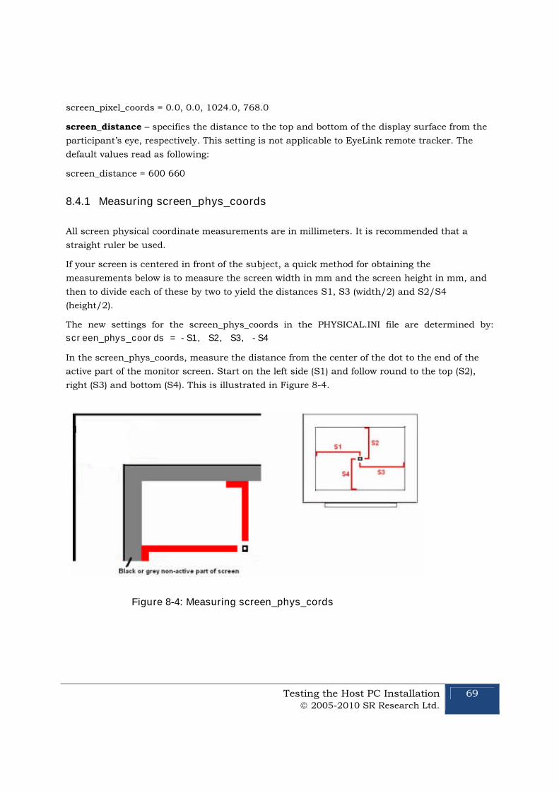
Testing the Host PC Installation 2005-2010 SR Research Ltd.
69
screen_pixel_coords = 0.0, 0.0, 1024.0, 768.0
screen_distance – specifies the distance to the top and bottom of the display surface from the
participant’s eye, respectively. This setting is not applicable to EyeLink remote tracker. The
default values read as following:
screen_distance = 600 660
8.4.1 Measuring screen_phys_coords
All screen physical coordinate measurements are in millimeters. It is recommended that a
straight ruler be used.
If your screen is centered in front of the subject, a quick method for obtaining the
measurements below is to measure the screen width in mm and the screen height in mm, and
then to divide each of these by two to yield the distances S1, S3 (width/2) and S2/S4
(height/2).
The new settings for the screen_phys_coords in the PHYSICAL.INI file are determined by:
screen_phys_coords = -S1, S2, S3, -S4
In the screen_phys_coords, measure the distance from the center of the dot to the end of the
active part of the monitor screen. Start on the left side (S1) and follow round to the top (S2),
right (S3) and bottom (S4). This is illustrated in Figure 8-4.
Figure 8-4: Measuring screen_phys_cords
70 Testing the Host PC Installation 2005-2010 SR Research Ltd.
8.4.2 Measuring screen_distance
Please follow the steps below to measure the “screen_distance” values. For EyeLink Remote eye
tracker, keep the default “screen_distance” value.
1. Set up the monitor and chinrest so that the chinrest is centered on the monitor and the
monitor is horizontally aligned with the chinrest (HINT: measure from the left and right
knobs on the chinrest to the left and right sides of the top of the display area of the
monitor, these should be equal).
2. Adjust the height and tilt of the monitor. Ideally this should have the top of the display at
about the same height as the forehead rest, and the display tilted up slightly. The tilt can
be changed if there are any reflection issues. Small amounts of horizontal misalignment
(turning of the monitor) may be tolerated if required to reduce screen reflections, but this
may reduce the accuracy of angular measures.
3. Now measure from the front of the forehead rest/Tower height adjustment knob (or the
subject’s eye position if using your own chin rest) to the point on the monitor directly in
front of the knob (lay the measuring tape across the top of the shaft of the knob, and read
distance from the front of the column). Measure from the knob to the top of the visible part
of the display area, then from the knob to the bottom of the display area. These two values
(in millimeters) should be your new “screen_distance” command values.
8.4.3 Entering Values into PHYSICAL.INI
The newly acquired values for “screen_phys_coords” and “screen_distance” must now be
entered into the PHYSICAL.INI located on the Host PC. This can be done either from the
Windows partition or from the EyeLink partition.
8.4.3.1 Windows Partition
Boot into the Windows partition, find the EyeLink drive. Go to the “ELCL\EXE” directory and
select the PHYSICAL.INI file. Uncheck the "read-only" property of the file. Modify the file and
save the change.
8.4.3.2 EyeLink Partition
Reboot the Host PC into the EyeLink partition. Do not press “T” when in the DOS prompt. If the
host software is already running, closing the host software will automatically bring you to
“C:\ELCL\EXE” directory.
From the command prompt type the following
CD C:\ELCL\EXE
ATTRIB –R PHYSICAL.INI
EDIT PHYSICAL.INI
Testing the Host PC Installation 2005-2010 SR Research Ltd.
71
To enter the new values, follow these steps
1. Go to the screen_distance parameter
2. Remove the default values for this command.
3. Enter new values
4. Repeat steps 1-3 for screen_phys_coords
5. Save changes and exit the file
Finish by typing the following at the command type
ATTRIB +R PHYSICAL.INI
72 Display PC Software Installation 2005-2010 SR Research Ltd.
9. Display PC Software Installation
The Display PC is used to run experiment application software for control of the EyeLink 1000
tracker and stimulus presentation through the EyeLink Display Software. This API is available
on Windows, MacOS and Linux platforms. The latest version of the display software can be
downloaded from SR Research support website http://www.sr-support.com. The Display PC
installation process should not take more than 15 minutes. Installation instructions for the
Windows platform are detailed below.
9.1 Windows Installation
To use a Windows Display computer with the EyeLink 1000 system, various EyeLink software
components should be installed. The installation process consists of the following basic steps:
Install the EyeLink Experiment Programming Kit.
Install the supplied IO Port Access Driver if planning to use TTL.
Install the EyeLink Data Viewer and / or Experiment Builder software (if
purchased).
Install the USB Key drivers for EyeLink Data Viewer and / or Experiment Builder
software (if purchased).
Configure the network connection to the EyeLink 1000 Host PC.
9.1.1 Installing the EyeLink 1000 Experiment Programming Kit
The Windows toolkit (API and example files) is available on the “EyeLink 1000 Software” CD in
the “Display PC Installation” directory. To install the toolkit:
1. Insert the “EyeLink 1000 Software” CD.
2. Open the “Display PC Installation → Windows” folder.
3. Run the EyeLinkDevKit_*.exe program by double clicking the icon.
4. Follow the instructions from the InstallShield Wizard to install the display software.
5. Wait for the InstallShield Wizard to finish, and click FINISH to complete installation.
9.1.2 Installing the IO Port Access Driver
For proper access to IO ports (i.e. for TTL signaling) on the Display PC, an access driver must
be installed. Note that this PORT95NT installer doesn’t run on any 64-bit versions of Windows
XP or Vista.
1. To install the driver, click Start → Programs → SR Research → EyeLink → Utilities →
PORT95NT.
Display PC Software Installation 2005-2010 SR Research Ltd.
73
2. Follow the on screen instructions.
3. Reboot your computer when prompted.
9.1.3 Installing the EyeLink Data Viewer and Experiment Builder Software
The EyeLink Data Viewer and Experiment Builder software are optional Windows applications
for the EyeLink eye tracker. If you did not purchase these options this section may be skipped,
or you may install the software for evaluation in demo mode.
1. Insert the “EyeLink 1000 Software” CD.
2. Open the “Display PC Installation → Windows-> EyeLink Data Viewer” folder.
3. Run the EyeLinkDV_*.exe program by double clicking the icon.
4. Follow the instructions from the InstallShield Wizard to install the software.
5. Wait for the InstallShield Wizard to finish, and click FINISH to complete installation.
6. Open the “Display PC Installation → Windows-> SR Research Experiment Builder”
folder
7. Run the SREB_*.exe program by double clicking the icon.
8. Follow the instructions from the InstallShield Wizard to install the software.
9. Wait for the InstallShield Wizard to finish, and click FINISH to complete installation.
9.1.4 USB License Key Installation
If you purchased either the Data Viewer or Experiment Builder software, you will have
been provided with a USB license key with your order. To install the software driver for the
USB license key follow these steps:
1. From the Windows Start menu select “Start->All Programs -> SR Research -> Install
HASP Driver”. You may also try running both “HASPUserSetup.exe” and “hdd32.exe”
installers contained in the “C:\Program Files\SR Research\Common” folder of the
display computer.
2. Follow the instructions from the InstallShield Wizard to install the software.
3. Wait for the InstallShield Wizard to finish, and click FINISH to complete installation.
4. Insert the USB Key into an available USB port on the Display computer. The USB key
should start to glow red, indicating that the key has been recognized by the system.
9.1.5 Setting up EyeLink 1000 Network Connection
You must have an Ethernet port in your Display Computer. Allow Windows to install drivers for
it (if it is new hardware), then follow these instructions to install and configure the TCP/IP
network protocol. These instructions are based on Windows XP; other Windows operating
systems may vary slightly.
74 Display PC Software Installation 2005-2010 SR Research Ltd.
1. From the Start menu select the Control Panel.
2. Click on the Network and Internet Connections icon, and then select the Network
Connections icon. Check the list of installed components to make sure a network card
is installed. If not, install a driver for the card.
3. Double click on the network card icon that represents the network card that will be
connected to the EyeLink 1000 Host PC.
4. Select the properties button.
5. Check that “TCP/IP” is displayed in the list of components and that it is checked. If not,
press the checkmark beside the option.
6. Select the “TCP/IP” component for the Ethernet card connected to the eye tracker PC,
then click on the “Properties” button.
7. Select the “Use the following IP address” radio button. Enter the IP address of
“100.1.1.2”. The last digit of the IP address can increase for other computers on the
EyeLink network. Enter the subnet mask of “255.255.255.0”. Leave the default
gateway and other settings blank.
8. Click on “OK” to return to the Properties dialog. Click “OK” again to save your changes.
Click “Close” to exit from the network card dialog.
If connectivity error messages appear ensure the supplied Ethernet crossover cable connects
the configured Ethernet port of the Disply PC to the supplied network card of the Host PC.
Alternatively, you may need to reinstall the network card drivers. To be safe, open the Network
dialog and remove all components, restart Windows, then install the network card driver and
the TCP/IP protocol again.
To test the network, start the EyeLink 1000 tracker and start the “Track” application from
“Start -> Programs -> SR Research -> EyeLink -> Track”. The link should connect, and the
screen will display instructions. This application allows you to practice participant setup and
test the system, as described in the EyeLink 1000 Installation Guide. If the message “Cannot
initialize link” appears, the TCP/IP protocol or crossover cable is/are not properly configured. If
the connection times out, it is probably due to the network card being improperly configured or
because the network cable is not connected to both PCs. On the Host PC, the Ethernet cable
should be connected to the Ethernet card we supplied (not to any other Ethernet ports!). The
display of a "NO HARDWARE" message in the "Camera Setup" screen indicates that tracker did
not reliably detect the Ethernet card. If you see this message, try re-seating the Ethernet card
or plugging it to a different slot.
9.1.6 System and Programming Tools Required
The C experiment templates in Windows Display Software package were developed using
Microsoft Visual C 6.0. Other 32-bit C and C++ compilers may be used, but you will have to
Display PC Software Installation 2005-2010 SR Research Ltd.
75
translate the included make files to rebuild the experiments. This release of the Windows
Display Software does not supply examples for C++ programming.
9.2 Mac OSX Installation
To use Mac OSX as a Display computer with the EyeLink 1000 system, various EyeLink
software components should be installed on the computer. The installation process consists of
the following basic steps:
Install the “Mac OSX Display Software”. The installer disk image is located in the
“Display PC Installation/Mac OSX” folder of the “EyeLink 1000 Software” CD – the
latest version of the software can be downloaded from SR Research Support website
(https://www.sr-support.com/forums/showthread.php?t=15).
Mount and open the disk image under MacOS, then click on the installer and follow
the instructions, using the default settings as prompted. The EyeLink libraries,
documentation and source code examples are installed in the Applications:EyeLink
folder.
Install the EyeLink Data Viewer. The installer disk image is located in the “Display
PC Installation/Mac OSX” folder of the “EyeLink 1000 Software” CD – the latest
version of the software can be downloaded from SR Research Support website
(https://www.sr-support.com/forums/showthread.php?t=10).
Mount and open the disk image under MacOS, then click on the installer and follow
the instructions, using the default settings as prompted. Data Viewer is installed in
the Applications:EyeLink DataViewer directory.
Install the USB HASP Key driver for EyeLink Data Viewer. Mount the
“Hdd_MacOSX.dmg” disk image to get access to the HASP driver installer. Double
click on the installer made available by the disk image and follow the instructions,
using the default settings as prompted.
Configure the network connection to the EyeLink 1000 Host PC. Set the IP address
to 100.1.1.2 and subnet mask to 255.255.255.0. You can do this by opening the
System Preferences (Apple menu item, then select ‘System Preferences…’) and click
on the Network Icon. Next go to your computer’s Built-In Ethernet device, select
Manually on the Configure pop-up menu, and enter the above IP address and
subnet mask. Click Apply to apply these new settings.
If you plan to program your experiments in MatLab, install the latest version of the
PsychToolBox and reboot the computer. Some demo examples can be found in the
Psychtoolbox directory which is in the Applications folder at:
"Applications/Psychtoolbox/PsychHardware/EyelinkToolbox/EyelinkDemos/GazeContingentD
emos".
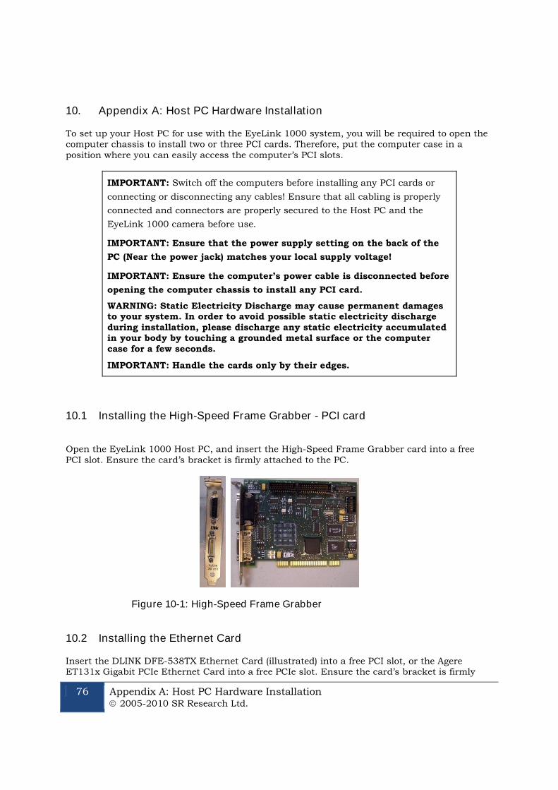
76 Appendix A: Host PC Hardware Installation 2005-2010 SR Research Ltd.
10. Appendix A: Host PC Hardware Installation
To set up your Host PC for use with the EyeLink 1000 system, you will be required to open thecomputer chassis to install two or three PCI cards. Therefore, put the computer case in aposition where you can easily access the computer’s PCI slots.
IMPORTANT: Switch off the computers before installing any PCI cards or
connecting or disconnecting any cables! Ensure that all cabling is properly
connected and connectors are properly secured to the Host PC and the
EyeLink 1000 camera before use.
IMPORTANT: Ensure that the power supply setting on the back of the
PC (Near the power jack) matches your local supply voltage!
IMPORTANT: Ensure the computer’s power cable is disconnected before
opening the computer chassis to install any PCI card.
WARNING: Static Electricity Discharge may cause permanent damagesto your system. In order to avoid possible static electricity dischargeduring installation, please discharge any static electricity accumulatedin your body by touching a grounded metal surface or the computercase for a few seconds.
IMPORTANT: Handle the cards only by their edges.
10.1 Installing the High-Speed Frame Grabber - PCI card
Open the EyeLink 1000 Host PC, and insert the High-Speed Frame Grabber card into a freePCI slot. Ensure the card’s bracket is firmly attached to the PC.
Figure 10-1: High-Speed Frame Grabber
10.2 Installing the Ethernet Card
Insert the DLINK DFE-538TX Ethernet Card (illustrated) into a free PCI slot, or the AgereET131x Gigabit PCIe Ethernet Card into a free PCIe slot. Ensure the card’s bracket is firmly
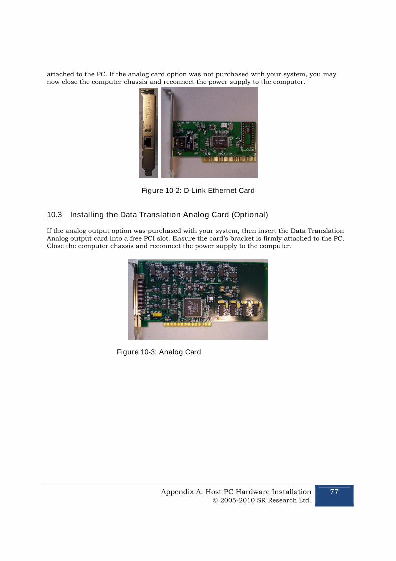
Appendix A: Host PC Hardware Installation 2005-2010 SR Research Ltd.
77
attached to the PC. If the analog card option was not purchased with your system, you maynow close the computer chassis and reconnect the power supply to the computer.
Figure 10-2: D-Link Ethernet Card
10.3 Installing the Data Translation Analog Card (Optional)
If the analog output option was purchased with your system, then insert the Data TranslationAnalog output card into a free PCI slot. Ensure the card’s bracket is firmly attached to the PC.Close the computer chassis and reconnect the power supply to the computer.
Figure 10-3: Analog Card
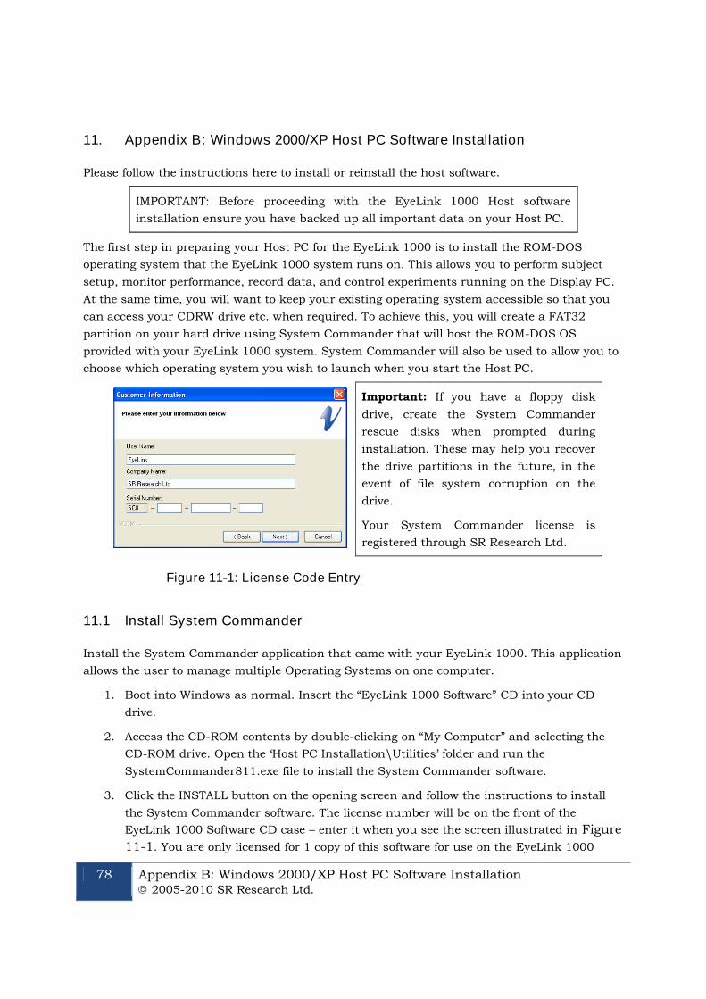
78 Appendix B: Windows 2000/XP Host PC Software Installation 2005-2010 SR Research Ltd.
11. Appendix B: Windows 2000/XP Host PC Software Installation
Please follow the instructions here to install or reinstall the host software.
IMPORTANT: Before proceeding with the EyeLink 1000 Host software
installation ensure you have backed up all important data on your Host PC.
The first step in preparing your Host PC for the EyeLink 1000 is to install the ROM-DOS
operating system that the EyeLink 1000 system runs on. This allows you to perform subject
setup, monitor performance, record data, and control experiments running on the Display PC.
At the same time, you will want to keep your existing operating system accessible so that you
can access your CDRW drive etc. when required. To achieve this, you will create a FAT32
partition on your hard drive using System Commander that will host the ROM-DOS OS
provided with your EyeLink 1000 system. System Commander will also be used to allow you to
choose which operating system you wish to launch when you start the Host PC.
Important: If you have a floppy disk
drive, create the System Commander
rescue disks when prompted during
installation. These may help you recover
the drive partitions in the future, in the
event of file system corruption on the
drive.
Your System Commander license is
registered through SR Research Ltd.
Figure 11-1: License Code Entry
11.1 Install System Commander
Install the System Commander application that came with your EyeLink 1000. This application
allows the user to manage multiple Operating Systems on one computer.
1. Boot into Windows as normal. Insert the “EyeLink 1000 Software” CD into your CD
drive.
2. Access the CD-ROM contents by double-clicking on “My Computer” and selecting the
CD-ROM drive. Open the ‘Host PC Installation\Utilities’ folder and run the
SystemCommander811.exe file to install the System Commander software.
3. Click the INSTALL button on the opening screen and follow the instructions to install
the System Commander software. The license number will be on the front of the
EyeLink 1000 Software CD case – enter it when you see the screen illustrated in Figure
11-1. You are only licensed for 1 copy of this software for use on the EyeLink 1000
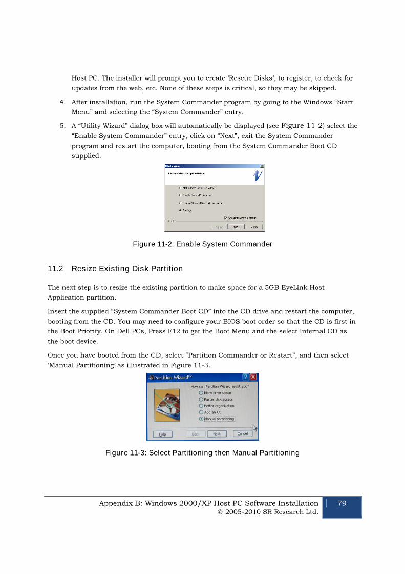
Appendix B: Windows 2000/XP Host PC Software Installation 2005-2010 SR Research Ltd.
79
Host PC. The installer will prompt you to create ‘Rescue Disks’, to register, to check for
updates from the web, etc. None of these steps is critical, so they may be skipped.
4. After installation, run the System Commander program by going to the Windows “Start
Menu” and selecting the “System Commander” entry.
5. A “Utility Wizard” dialog box will automatically be displayed (see Figure 11-2) select the
“Enable System Commander” entry, click on “Next”, exit the System Commander
program and restart the computer, booting from the System Commander Boot CD
supplied.
Figure 11-2: Enable System Commander
11.2 Resize Existing Disk Partition
The next step is to resize the existing partition to make space for a 5GB EyeLink Host
Application partition.
Insert the supplied “System Commander Boot CD” into the CD drive and restart the computer,
booting from the CD. You may need to configure your BIOS boot order so that the CD is first in
the Boot Priority. On Dell PCs, Press F12 to get the Boot Menu and the select Internal CD as
the boot device.
Once you have booted from the CD, select “Partition Commander or Restart”, and then select
‘Manual Partitioning’ as illustrated in Figure 11-3.
Figure 11-3: Select Partitioning then Manual Partitioning
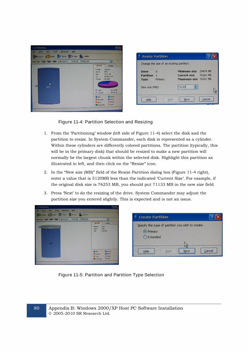
80 Appendix B: Windows 2000/XP Host PC Software Installation 2005-2010 SR Research Ltd.
Figure 11-4: Partition Selection and Resizing
1. From the ‘Partitioning’ window (left side of Figure 11-4) select the disk and the
partition to resize. In System Commander, each disk is represented as a cylinder.
Within these cylinders are differently colored partitions. The partition (typically, this
will be in the primary disk) that should be resized to make a new partition will
normally be the largest chunk within the selected disk. Highlight this partition as
illustrated in left, and then click on the “Resize” icon.
2. In the “New size (MB)” field of the Resize Partition dialog box (Figure 11-4 right),
enter a value that is 5120MB less than the indicated ‘Current Size’. For example, if
the original disk size is 76253 MB, you should put 71133 MB in the new size field.
3. Press ‘Next’ to do the resizing of the drive. System Commander may adjust the
partition size you entered slightly. This is expected and is not an issue.
Figure 11-5: Partition and Partition Type Selection
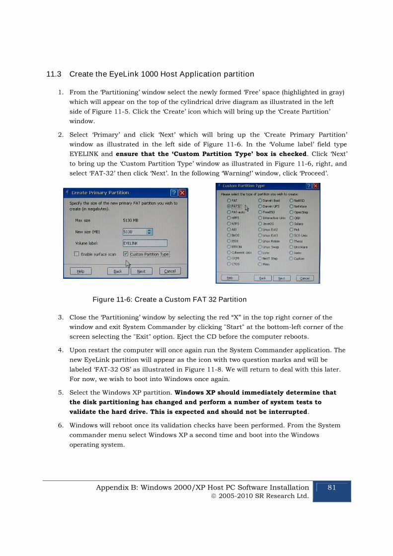
Appendix B: Windows 2000/XP Host PC Software Installation 2005-2010 SR Research Ltd.
81
11.3 Create the EyeLink 1000 Host Application partition
1. From the ‘Partitioning’ window select the newly formed ‘Free’ space (highlighted in gray)
which will appear on the top of the cylindrical drive diagram as illustrated in the left
side of Figure 11-5. Click the ‘Create’ icon which will bring up the ‘Create Partition’
window.
2. Select ‘Primary’ and click ‘Next’ which will bring up the ‘Create Primary Partition’
window as illustrated in the left side of Figure 11-6. In the ‘Volume label’ field type
EYELINK and ensure that the ‘Custom Partition Type’ box is checked. Click ‘Next’
to bring up the ‘Custom Partition Type’ window as illustrated in Figure 11-6, right, and
select ‘FAT-32’ then click ‘Next’. In the following ‘Warning!’ window, click ‘Proceed’.
Figure 11-6: Create a Custom FAT 32 Partition
3. Close the ‘Partitioning’ window by selecting the red “X” in the top right corner of the
window and exit System Commander by clicking "Start" at the bottom-left corner of the
screen selecting the "Exit" option. Eject the CD before the computer reboots.
4. Upon restart the computer will once again run the System Commander application. The
new EyeLink partition will appear as the icon with two question marks and will be
labeled ‘FAT-32 OS’ as illustrated in Figure 11-8. We will return to deal with this later.
For now, we wish to boot into Windows once again.
5. Select the Windows XP partition. Windows XP should immediately determine that
the disk partitioning has changed and perform a number of system tests to
validate the hard drive. This is expected and should not be interrupted.
6. Windows will reboot once its validation checks have been performed. From the System
commander menu select Windows XP a second time and boot into the Windows
operating system.
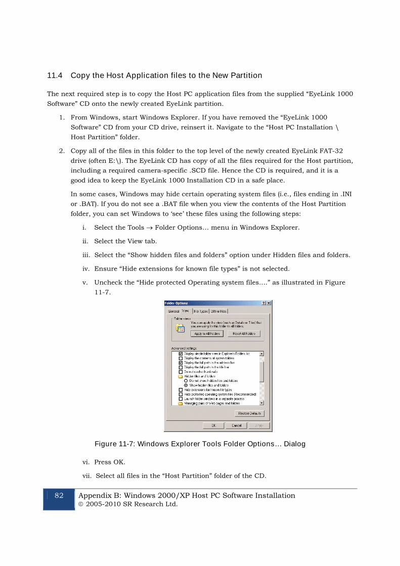
82 Appendix B: Windows 2000/XP Host PC Software Installation 2005-2010 SR Research Ltd.
11.4 Copy the Host Application files to the New Partition
The next required step is to copy the Host PC application files from the supplied “EyeLink 1000
Software” CD onto the newly created EyeLink partition.
1. From Windows, start Windows Explorer. If you have removed the “EyeLink 1000
Software” CD from your CD drive, reinsert it. Navigate to the “Host PC Installation \
Host Partition” folder.
2. Copy all of the files in this folder to the top level of the newly created EyeLink FAT-32
drive (often E:\). The EyeLink CD has copy of all the files required for the Host partition,
including a required camera-specific .SCD file. Hence the CD is required, and it is a
good idea to keep the EyeLink 1000 Installation CD in a safe place.
In some cases, Windows may hide certain operating system files (i.e., files ending in .INI
or .BAT). If you do not see a .BAT file when you view the contents of the Host Partition
folder, you can set Windows to ‘see’ these files using the following steps:
i. Select the Tools Folder Options… menu in Windows Explorer.
ii. Select the View tab.
iii. Select the “Show hidden files and folders” option under Hidden files and folders.
iv. Ensure “Hide extensions for known file types” is not selected.
v. Uncheck the “Hide protected Operating system files….” as illustrated in Figure
11-7.
Figure 11-7: Windows Explorer Tools Folder Options… Dialog
vi. Press OK.
vii. Select all files in the “Host Partition” folder of the CD.

Appendix B: Windows 2000/XP Host PC Software Installation 2005-2010 SR Research Ltd.
83
viii. Copy these files to the root directory of the EyeLink 1000 drive on your
computer.
3. To return Windows so that it hides operating system files complete the following steps:
i. Select the Tools Folder Options… menu in Windows Explorer.
ii. Select the View tab.
iii. Deselect the “Show hidden files and folders” option under Hidden files and
folders.
iv. Check the “Hide protected Operating system files….”
4. If you have a PS/2 keyboard please continue to section “11.6, Transfer the System to
make the EyeLink Partition Bootable”
11.5 Configuring the Keyboard
The PS/2 keyboard is the default driver setup within the EyeLink Host directory, and is the
only keyboard hardware recommended for the latest versions of the Host Application.
11.6 Transfer the System to make the EyeLink Partition Bootable
1. Insert the CD labeled “ROM-DOS Boot Disk” that came with the EyeLink 1000 system,
and restart the system as you normally would via Windows. The next step is to boot off
of the CD. You may need to press F12 before System Commander is run to boot off of
the CD-ROM device. With some newer types of hardware choosing to boot from the CD-
ROM from within System Commander does not work as desired.
2. You will know that you have successfully booted from the CD-ROM of you are given a
ROM-DOS command prompt.
IMPORTANT: The following step requires you to determine the correct drive
letter (c:, d:, etc) for the EyeLink 1000 partition you created above after
booting with the ROM-DOS Boot Disk. Determine this by using the dir
command (e.g. dir c:) for each drive to find the EyeLink drive label and
substitute that drive letter (c:, d:, etc) in place of {EYELINK DRIVE} below. It
is likely that the drive letter will be either c: or d:
3. At the command prompt 'A:\>’ type the following command:
sys {EYELINK DRIVE} [ENTER]
For example if your EyeLink partition is drive c: you will enter:
sys c:
and then press the enter key.
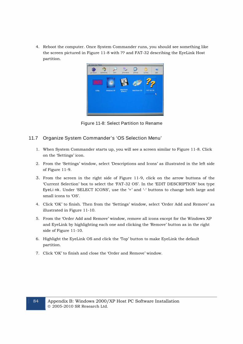
84 Appendix B: Windows 2000/XP Host PC Software Installation 2005-2010 SR Research Ltd.
4. Reboot the computer. Once System Commander runs, you should see something like
the screen pictured in Figure 11-8 with ?? and FAT-32 describing the EyeLink Host
partition.
Figure 11-8: Select Partition to Rename
11.7 Organize System Commander’s ‘OS Selection Menu’
1. When System Commander starts up, you will see a screen similar to Figure 11-8. Click
on the ‘Settings’ icon.
2. From the ‘Settings’ window, select ‘Descriptions and Icons’ as illustrated in the left side
of Figure 11-9.
3. From the screen in the right side of Figure 11-9, click on the arrow buttons of the
‘Current Selection’ box to select the ‘FAT-32 OS’. In the ‘EDIT DESCRIPTION’ box type
EyeLink. Under ‘SELECT ICONS’, use the ’+’ and ‘-‘ buttons to change both large and
small icons to ‘OS’.
4. Click ‘OK’ to finish. Then from the ‘Settings’ window, select ‘Order Add and Remove’ as
illustrated in Figure 11-10.
5. From the ‘Order Add and Remove’ window, remove all icons except for the Windows XP
and EyeLink by highlighting each one and clicking the ‘Remove’ button as in the right
side of Figure 11-10.
6. Highlight the EyeLink OS and click the ‘Top’ button to make EyeLink the default
partition.
7. Click ‘OK’ to finish and close the ‘Order and Remove’ window.
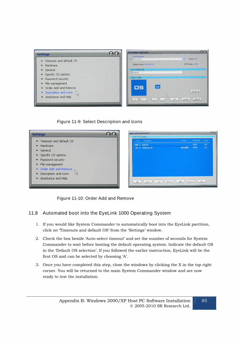
Appendix B: Windows 2000/XP Host PC Software Installation 2005-2010 SR Research Ltd.
85
Figure 11-9: Select Description and Icons
Figure 11-10: Order Add and Remove
11.8 Automated boot into the EyeLink 1000 Operating System
1. If you would like System Commander to automatically boot into the EyeLink partition,
click on ‘Timeouts and default OS’ from the ‘Settings’ window.
2. Check the box beside ‘Auto-select timeout’ and set the number of seconds for System
Commander to wait before booting the default operating system. Indicate the default OS
in the ‘Default OS selection’. If you followed the earlier instruction, EyeLink will be the
first OS and can be selected by choosing ‘A’.
3. Once you have completed this step, close the windows by clicking the X in the top right
corner. You will be returned to the main System Commander window and are now
ready to test the installation.

86 Appendix C: Host PC Software Installation Under Windows Vista 2005-2010 SR Research Ltd.
12. Appendix C: Host PC Software Installation Under Windows Vista
Please follow the instructions here to install the Host software in conjunction with Windows
Vista.
IMPORTANT: Before proceeding with the EyeLink 1000 Host software
installation ensure you have backed up all important data on your Host PC.
A new Windows Vista installation is required and this WILL erase everything
on the hard drive. We do not have the ability to separately create the Host
partition with an already existing Vista installation.
WARNING: ALL DATA ON THE DISK WILL BE ERASED
Due to the nature of Windows Vista’s boot loader, a full installation of Windows Vista must be
performed. This means that the hard drive will be formatted and any information on the hard
drive will be erased.
We will first format the hard drive using ROM-DOS and create a FAT32 partition for the
EyeLink Host software. Next, Windows Vista will be installed on the unused portion of the
drive. Finally, under Vista, we will configure the boot loader so that the system can be booted
into either ROM-DOS or Windows Vista.
You will require:
a ROM-DOS Boot CD (supplied with your EyeLink or disk image available via
a copy of your EyeLink 1000 CD-ROM (or “EyeLink CL” CD-ROM) containing the Host
PC application software and your .SCD file (supplied with your EyeLink)
a copy of your Vista installation disk and Vista License
12.1 Formatting the Hard Drive under ROM-DOS
The first step in preparing your Host PC for the EyeLink 1000 and Vista is to format your hard
drive using the ROM-DOS operating system, and creating a partition for the EyeLink Host
software.
1. Boot the computer with the ROM-DOS Boot CD. If you are using a Dell computer, placethe CD in the CD-ROM drive and press F12 for booting options, and boot from theInternal or USB CD-ROM drive. For other motherboards and systems, you may need toenter the BIOS and change the Boot Priority of the different drive components, in orderto make the CD-ROM have the highest boot priority.
2. At the command line prompt type "FDISK" without quotes.
3. While running FDISK:
i. type 'A' and delete all partitions
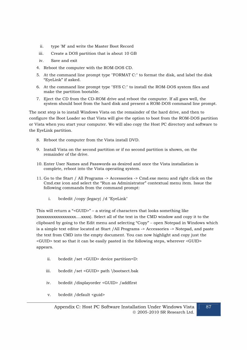
Appendix C: Host PC Software Installation Under Windows Vista 2005-2010 SR Research Ltd.
87
ii. type 'M' and write the Master Boot Record
iii. Create a DOS partition that is about 10 GB
iv. Save and exit
4. Reboot the computer with the ROM-DOS CD.
5. At the command line prompt type "FORMAT C:" to format the disk, and label the disk“EyeLink” if asked.
6. At the command line prompt type "SYS C:" to install the ROM-DOS system files andmake the partition bootable.
7. Eject the CD from the CD-ROM drive and reboot the computer. If all goes well, thesystem should boot from the hard disk and present a ROM-DOS command line prompt.
The next step is to install Windows Vista on the remainder of the hard drive, and then to
configure the Boot Loader so that Vista will give the option to boot from the ROM-DOS partition
or Vista when you start your computer. We will also copy the Host PC directory and software to
the EyeLink partition.
8. Reboot the computer from the Vista install DVD.
9. Install Vista on the second partition or if no second partition is shown, on theremainder of the drive.
10. Enter User Names and Passwords as desired and once the Vista installation iscomplete, reboot into the Vista operating system.
11. Go to the Start / All Programs -> Accessories -> Cmd.exe menu and right click on theCmd.exe icon and select the “Run as Administrator” contextual menu item. Issue thefollowing commands from the command prompt:
i. bcdedit /copy {legacy} /d "EyeLink"
This will return a “<GUID>” – a string of characters that looks something like
{xxxxxxxxxxxxxxxxx....xxxx}. Select all of the text in the CMD window and copy it to the
clipboard by going to the Edit menu and selecting “Copy” – open Notepad in Windows which
is a simple text editor located at Start /All Programs -> Accessories -> Notepad, and paste
the text from CMD into the empty document. You can now highlight and copy just the
<GUID> text so that it can be easily pasted in the following steps, wherever <GUID>
appears.
ii. bcdedit /set <GUID> device partition=D:
iii. bcdedit /set <GUID> path \bootsect.bak
iv. bcdedit /displayorder <GUID> /addfirst
v. bcdedit /default <guid>

88 Appendix C: Host PC Software Installation Under Windows Vista 2005-2010 SR Research Ltd.
12. Reboot the computer and select "Eyelink" on the menu to go into the EyeLink partition or
select Windows Vista to boot into Vista. You can now copy the EyeLink Host Partition files from
your EyeLink 1000 (or EyeLink CL) distribution disk to put the host software on the EyeLink
partition. See Section 11.4 "Copy the Host Application files to the New Partition" for
instructions.
Related Documents


