International Journal of Computer Science, Engineering and Information Technology (IJCSEIT), Vol. 5,No.2, April 2015 DOI : 10.5121/ijcseit.2015.5202 15 EYE SCRUTINIZED WHEEL CHAIR FOR PEOPLE AFFECTED WITH TETRAPLEGIA Mrs.B.Buvanswari 1 and Dr. T.Kalpalatha Reddy 2 1 Research Scholar, Department of Computer Science Engineering, Sathyabama University, Chennai. 2 Dean R & D, Department of ECE, S.K.R Engineering College, Chennai ABSTRACT Nowadays the requirement for developing a wheel chair control which is useful for the physically disabled person with Tetraplegia. This system involves the control of the wheel chair with the eye moment of the affected person. Statistics suggest that there are 230,000 cases of Tetraplegia in India. Our system here is to develop a wheelchair which make the lives of these people easier and instigate confidence to live in them. We know that a person who is affected by Tetraplegia can move their eyes alone to a certain extent which paves the idea for the development of our system. Here we have proposed the method for a device where a patient placed on the wheel chair looking in a straight line at the camera which is permanently fixed in the optics, is capable to move in a track by gazing in that way. When we change the direction, the camera signals are given using the mat lab script to the microcontroller. Depends on the path of the eye, the microcontroller controls the wheel chair in all direction and stops the movement. If there is any obstacle to be found before the wheel chair the sensor mind that and it stop and move in right direction immediately. The benefit of this system is too easily travel anywhere in any direction which is handled by physically disabled person with Tetraplegia. KEYWORDS: Daugman‘s, Eye movement, Electronic wheel chair, Microcontroller, Tetraplegia. 1. INTRODUCTION The spinal cord injury occurs which means the failure of sensation or movement to some extent in the legs, bowel, bladder, and sexual region is referred as Tetraparesis .Paraplegia is similar but does not affect the arms. The loss is usually sensory and motor, which means that both sensation and control are lost. Tetraparesis, on the one-time hand, which means muscle failing affecting all four limbs. It may well be flaccid or spastic. Tetraplegia is root cause by damage to the brain or the spinal cord at a high level in particular, spinal cord injuries secondary to the cervical spine . The injury, which is identified as a lesion , causes sufferers to lose biased or total function of all four limbs, significance the arms and the legs. Tetraplegia is defined in many ways , usually affects arm movement supplementary so than a other can injury. On the other hand, all tetraplegics have some kind of finger dysfunction. For person with this disability, many different kind of electrical and robotic wheelchairs have been designed. These people have troubles to use a predictable wheelchair. A current clinical review indicated that 9%–10% of patients who received power wheelchair training establish it tremendously complicated or impossible to use it for their actions of daily livelihood, and 40% of patients found the direction-finding tasks difficult

Welcome message from author
This document is posted to help you gain knowledge. Please leave a comment to let me know what you think about it! Share it to your friends and learn new things together.
Transcript
International Journal of Computer Science, Engineering and Information Technology (IJCSEIT), Vol. 5,No.2, April 2015
DOI : 10.5121/ijcseit.2015.5202 15
EYE SCRUTINIZED WHEEL CHAIR FOR PEOPLE
AFFECTED WITH TETRAPLEGIA
Mrs.B.Buvanswari1
and Dr. T.Kalpalatha Reddy2
1Research Scholar, Department of Computer Science Engineering, Sathyabama
University, Chennai. 2Dean R & D, Department of ECE, S.K.R Engineering College, Chennai
ABSTRACT
Nowadays the requirement for developing a wheel chair control which is useful for the physically disabled
person with Tetraplegia. This system involves the control of the wheel chair with the eye moment of the
affected person. Statistics suggest that there are 230,000 cases of Tetraplegia in India. Our system here is
to develop a wheelchair which make the lives of these people easier and instigate confidence to live in
them. We know that a person who is affected by Tetraplegia can move their eyes alone to a certain extent
which paves the idea for the development of our system. Here we have proposed the method for a device
where a patient placed on the wheel chair looking in a straight line at the camera which is permanently
fixed in the optics, is capable to move in a track by gazing in that way. When we change the direction, the
camera signals are given using the mat lab script to the microcontroller. Depends on the path of the eye,
the microcontroller controls the wheel chair in all direction and stops the movement. If there is any
obstacle to be found before the wheel chair the sensor mind that and it stop and move in right direction
immediately. The benefit of this system is too easily travel anywhere in any direction which is handled by
physically disabled person with Tetraplegia.
KEYWORDS:
Daugman‘s, Eye movement, Electronic wheel chair, Microcontroller, Tetraplegia.
1. INTRODUCTION
The spinal cord injury occurs which means the failure of sensation or movement to some extent in
the legs, bowel, bladder, and sexual region is referred as Tetraparesis .Paraplegia is similar but
does not affect the arms. The loss is usually sensory and motor, which means that both sensation
and control are lost. Tetraparesis, on the one-time hand, which means muscle failing affecting all
four limbs. It may well be flaccid or spastic. Tetraplegia is root cause by damage to the brain or
the spinal cord at a high level in particular, spinal cord injuries secondary to the cervical spine .
The injury, which is identified as a lesion , causes sufferers to lose biased or total function of all
four limbs, significance the arms and the legs. Tetraplegia is defined in many ways , usually
affects arm movement supplementary so than a other can injury. On the other hand, all
tetraplegics have some kind of finger dysfunction. For person with this disability, many different
kind of electrical and robotic wheelchairs have been designed. These people have troubles to use
a predictable wheelchair. A current clinical review indicated that 9%–10% of patients who
received power wheelchair training establish it tremendously complicated or impossible to use it
for their actions of daily livelihood, and 40% of patients found the direction-finding tasks difficult

International Journal of Computer Science, Engineering and Information Technology (IJCSEIT), Vol. 5,No.2, April 2015
16
or impossible. These people are needy others to move forward them, so that they often feel
powerless and out of control. An eye tracking method is proposed here. The design of eye
monitored wheel chair was stimulated by past system such as hand over gesture based wheel
chair which involves the direction-finding of wheel chair using hand over gestures. In that system
the hand movements of the disabled person was used to guide the wheel in the desired direction.
We required to proposing our system by devious wheel chair for people affected with Tetraplegia
and provided that more independency. A camera is provided that to user for controlled by their
eye movements. By the eye movements the wheel chair will drive in all direction with accurate
way.
2. PROBLEM STATEMENT
The vision-controlled wheelchair is not easy to organize. The present system to control eye
movement and the suitability of position correction will have an effect on the systematic control.
However, investigate on maimed supplementary instrument still has positive significance in
provided that the handicapped chance to acquire greater mobility. So we proposed an eye
movement controlled based wheel chair for physically challenged persons to travel in any
desirable direction.
3. LITERATURE SURVEY
The employment of these(i.e. used difficult input devices) has caused inconvenience to the
physically disabled person. In this system, a computer input device by human eyes only is
proposed for handicapped person and also for wearable computing. There are various types of
wheel chair in the existing system.
Hand Gesture Based Wheelchair Movement:
A wheel chair control which is used for the physically disabled person with his hand movement
or his hand gesture recognition by using Acceleration technology. It has two operation modes
which are based on head movements: Mode 1 uses simply one head movement to give the
command to control, and Mode 2 employs one to four head movement. An EEG tool, namely
Emotiv EPOC, have been deployed in this HMI to attain the head movement information of
users.
Drawbacks:
It requires human effort to navigate devices which proves to be difficult for people with
deformities.
Voice Operated Wheel Chair
The wheel chair is controlled with the voice command from the handicapped person. Voice
command is given from android mobile and transformed into the text and this text is given to
microcontroller via bluetooth component to control the operation of DC motors. A handicapped
person still with Legs and Hand can use this and become autonomous. Some of the advantages
identified are rapidly changing input can be easily recognized due to android mobile, suitable for
International Journal of Computer Science, Engineering and Information Technology (IJCSEIT), Vol. 5,No.2, April 2015
17
practical application as compared to HM 2007,requires less wiring because of Bluetooth section,
less hardware requirement i.e. compact, economical, reduces manpower and user friendly .
Drawbacks:
• Less accurate on
• Background Noise
• Speaker variability
• Speaking style
• Speed of the speech.
Implementation of Head and Finger Based Automated Wheel Chair:
A head and finger based controlled assist system is developed to control the motor rotation of
wheel chair through head and finger movement of physically challenged person. On basis of the
head and finger movements the accelerometer and the flex sensor will force the motor fitted to the
wheel chair. It will be able to driven in any of the four directions. The automatic wheelchair
works on simple electronic control system and the automatic arrangement that is controlled by a
Programmable Interface Controller.
Drawbacks:
� It proves to be a burden to user.
� The flex sensor value was predictable to be within a small value, only few combinations
have been brought.
� Hardware has also been done to validate this technology.
Eye Movement Tracking For Wheelchair Control:
This system proposes a new algorithm called coherence algorithm, for eye motion tracking. This
system presents an function of eye tracking process to such wheelchairs. The coherence algorithm
tracks the movement of eye in moreover left or right direction. The eye movement discontinuous
feature is also used by the algorithm to organize the starting and stopping of wheelchair. This is
used as the inspiring factor for the improvement of our system.
4. PROPOSED METHODOLOGY
System Overview
Consists of three main parts:
� A camera connected to the laptop system that will track the camera wearer‘s eye.
� The microprocessor will receive a USB output from the laptop and translate the digital
output to electric signals that will be sent to the wheelchair for movement through the
microcontroller chip.
� A signal activate Wheel Chair
International Journal of Computer Science, Engineering and Information Technology (IJCSEIT), Vol. 5,No.2, April 2015
18
General Architecture
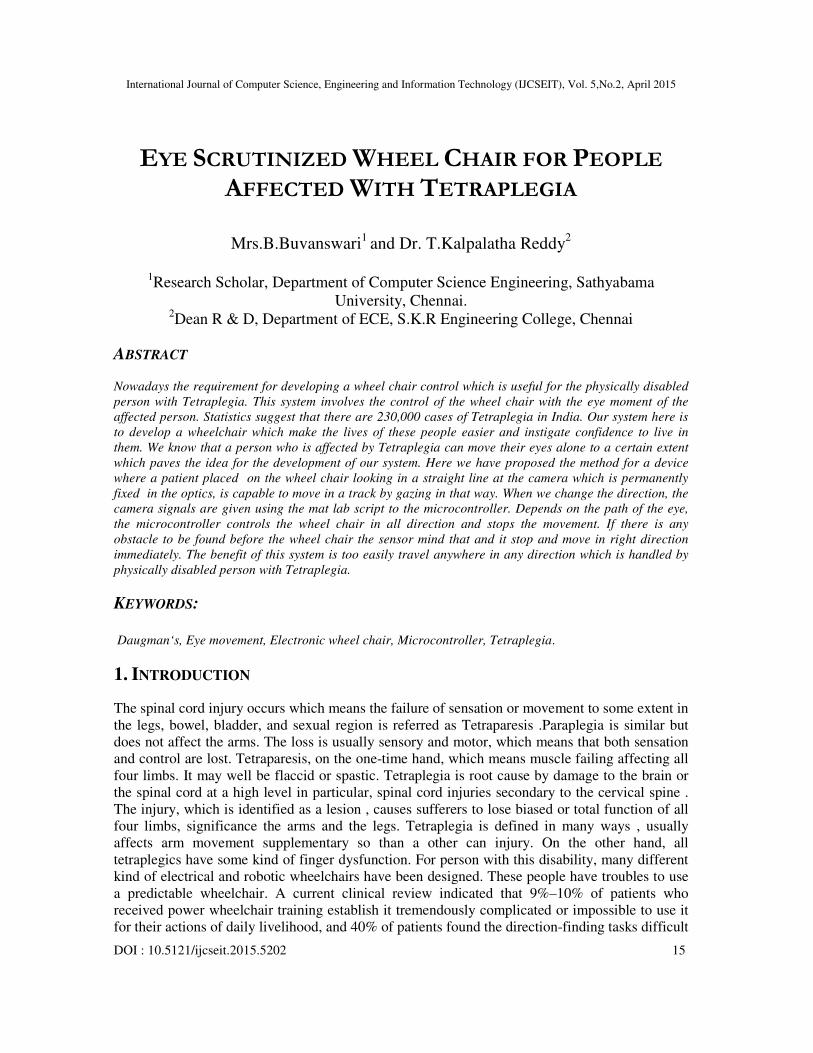
Figure.1 General Architecture for proposed System
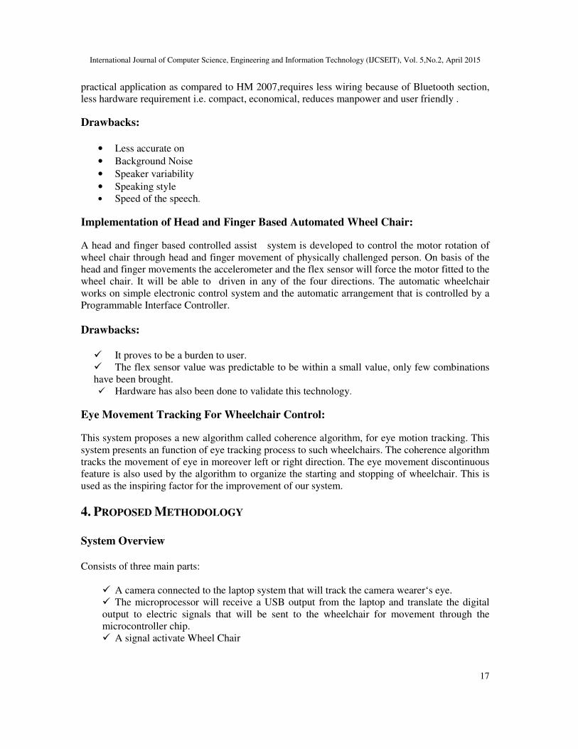
In Image Capturing component, we capture the image and after perfect capturing of image it send
to Image investigation Module where segmentation of image is done and dealing out of finding
the pupil and its path is found out. In the image analysis model, we separate the iris and the
segmentation of the patient’s eye using Hough Transform.
Figure.2. Overall System Process
Camera Staring At The Patient :
It involves two functions namely,
• Image Capturing Method
• Image Processing Method
Image Capturing System
Image Capturing is to capture a series of iris images from the topic using a specially designed
camera. In iris identification image capturing is a very important step. In sight of the fact that iris
is small in size and dark in color, it is not easy to acquire good image. The image is then altered
from RGB to gray level for more processing. It is to capture a series of iris images from the topic
using a specifically arranged camera. A standard diameter of 12 mm, a camera be required to
have sufficient motion to capture the details of the iris pattern.
Image Processing System
The role of segmentation is to remove non useful information, exclusively the pupil part and the
part outside the iris (sclera, eyelids, skin). Daugman recommended an integrodifferential operator
to position both the pupil and the iris outline. The algorithm will carry out the iris recognition in
two phases. In the first phase, uses the facts that a pupil is a very dark blob of certain minimum
International Journal of Computer Science, Engineering and Information Technology (IJCSEIT), Vol. 5,No.2, April 2015
19
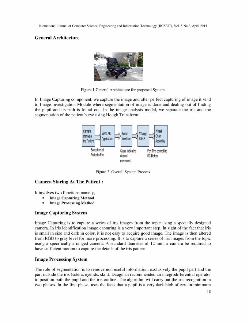
size picture, and no additional segment of continuous dark pixels are of the same size. The
algorithm discovers the center of the pupil and the two radial coefficients as the pupil is
constantly a perfect circle. The second algorithms receive the information of the pupil canter and
try to find direction in which the eye looks.
• Discover the center of the pupil .
• Discovery of the track in which eye looks.
Discovery of the track in which eye looks
The arrangement of the process that was diminish the complexity obviously by scale down every
part of images to a constant image size to speed up the entire process. First step is to compute the
Gaussian blur function. Gaussian blur is the outcome of blurring an image by a Gaussian
function.
Mathematically, concern a Gaussian blur to an image is the similar as convolving the image with
a Gaussian function. This is always called as a two-dimensional Weierstrass transform. The
Gaussian blur is a category of image-blurring filters uses a it function for compute the conversion
to be significant to each pixel in the image.
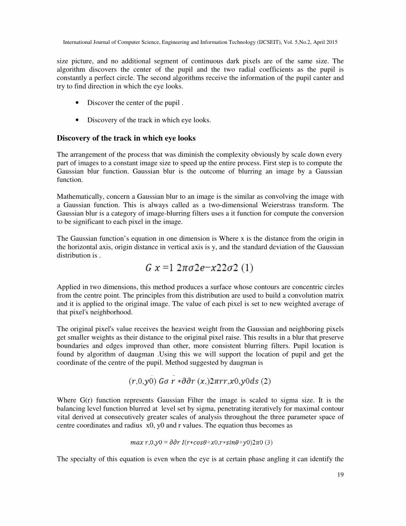
The Gaussian function’s equation in one dimension is Where x is the distance from the origin in
the horizontal axis, origin distance in vertical axis is y, and the standard deviation of the Gaussian
distribution is .
Applied in two dimensions, this method produces a surface whose contours are concentric circles
from the centre point. The principles from this distribution are used to build a convolution matrix
and it is applied to the original image. The value of each pixel is set to new weighted average of
that pixel's neighborhood.
The original pixel's value receives the heaviest weight from the Gaussian and neighboring pixels
get smaller weights as their distance to the original pixel raise. This results in a blur that preserve
boundaries and edges improved than other, more consistent blurring filters. Pupil location is
found by algorithm of daugman .Using this we will support the location of pupil and get the
coordinate of the centre of the pupil. Method suggested by daugman is
Where G(r) function represents Gaussian Filter the image is scaled to sigma size. It is the
balancing level function blurred at level set by sigma, penetrating iteratively for maximal contour
vital derived at consecutively greater scales of analysis throughout the three parameter space of
centre coordinates and radius x0, y0 and r values. The equation thus becomes as
The specialty of this equation is even when the eye is at certain phase angling it can identify the
International Journal of Computer Science, Engineering and Information Technology (IJCSEIT), Vol. 5,No.2, April 2015
20
center of the pupil, this is because line integration is inspection the maximum gradient circle in
that particular center values. It is a particular spot it going to verify at what angle the gradient is
highest. After achieved the center coordinates of both iris and pupil we make sure both circles
doesn‘t make bigger and stays surrounded by the other is inside iris circle and pupil circle should
be there and therefore determined that the obtained circles are accurate and if fails then resume of
the entire process takes place.
Identifying the direction of the pupil
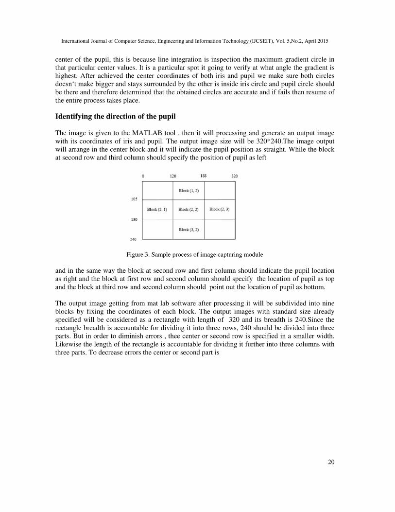
The image is given to the MATLAB tool , then it will processing and generate an output image
with its coordinates of iris and pupil. The output image size will be 320*240.The image output
will arrange in the center block and it will indicate the pupil position as straight. While the block
at second row and third column should specify the position of pupil as left
Figure.3. Sample process of image capturing module
and in the same way the block at second row and first column should indicate the pupil location
as right and the block at first row and second column should specify the location of pupil as top
and the block at third row and second column should point out the location of pupil as bottom.
The output image getting from mat lab software after processing it will be subdivided into nine
blocks by fixing the coordinates of each block. The output images with standard size already
specified will be considered as a rectangle with length of 320 and its breadth is 240.Since the
rectangle breadth is accountable for dividing it into three rows, 240 should be divided into three
parts. But in order to diminish errors , thee center or second row is specified in a smaller width.
Likewise the length of the rectangle is accountable for dividing it further into three columns with
three parts. To decrease errors the center or second part is
International Journal of Computer Science, Engineering and Information Technology (IJCSEIT), Vol. 5,No.2, April 2015
21
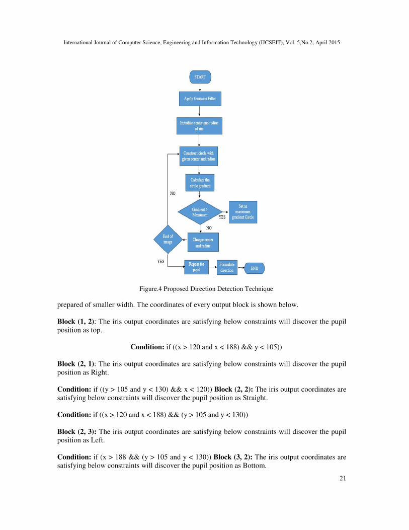
Figure.4 Proposed Direction Detection Technique
prepared of smaller width. The coordinates of every output block is shown below.
Block (1, 2): The iris output coordinates are satisfying below constraints will discover the pupil
position as top.
Condition: if ((x > 120 and x < 188) && y < 105))
Block (2, 1): The iris output coordinates are satisfying below constraints will discover the pupil
position as Right.
Condition: if ((y > 105 and y < 130) && x < 120)) Block (2, 2): The iris output coordinates are
satisfying below constraints will discover the pupil position as Straight.
Condition: if ((x > 120 and x < 188) && (y > 105 and y < 130))
Block (2, 3): The iris output coordinates are satisfying below constraints will discover the pupil
position as Left.
Condition: if (x > 188 && (y > 105 and y < 130)) Block (3, 2): The iris output coordinates are
satisfying below constraints will discover the pupil position as Bottom.
International Journal of Computer Science, Engineering and Information Technology (IJCSEIT), Vol. 5,No.2, April 2015
22
Condition: if ((x > 120 and x < 188) && y > 105))
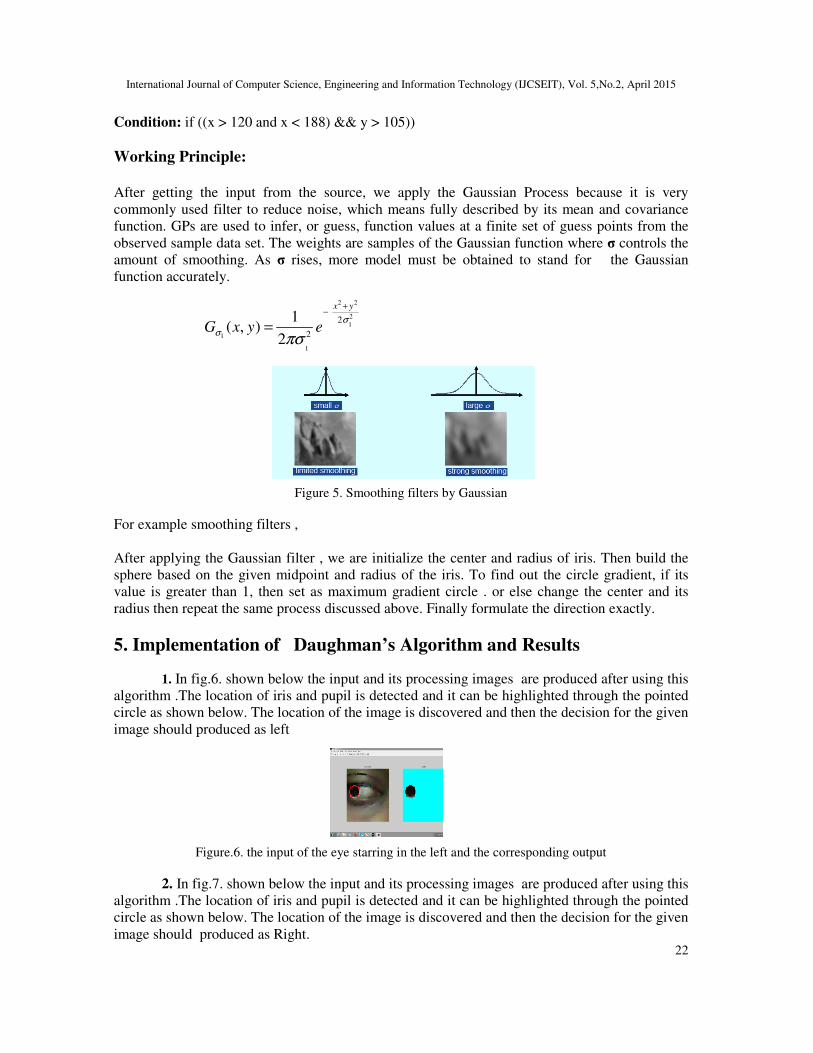
Working Principle:
After getting the input from the source, we apply the Gaussian Process because it is very
commonly used filter to reduce noise, which means fully described by its mean and covariance
function. GPs are used to infer, or guess, function values at a finite set of guess points from the
observed sample data set. The weights are samples of the Gaussian function where σ controls the
amount of smoothing. As σ rises, more model must be obtained to stand for the Gaussian
function accurately.
Figure 5. Smoothing filters by Gaussian
For example smoothing filters ,
After applying the Gaussian filter , we are initialize the center and radius of iris. Then build the
sphere based on the given midpoint and radius of the iris. To find out the circle gradient, if its
value is greater than 1, then set as maximum gradient circle . or else change the center and its
radius then repeat the same process discussed above. Finally formulate the direction exactly.
5. Implementation of Daughman’s Algorithm and Results
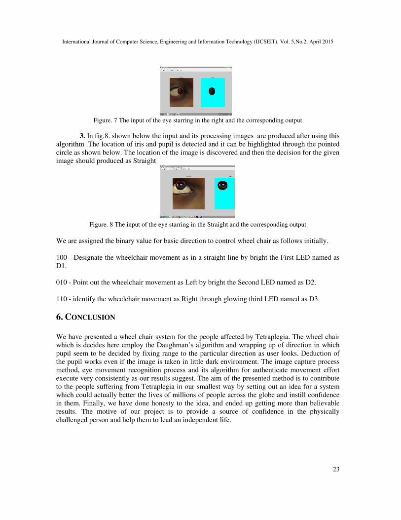
1. In fig.6. shown below the input and its processing images are produced after using this
algorithm .The location of iris and pupil is detected and it can be highlighted through the pointed
circle as shown below. The location of the image is discovered and then the decision for the given
image should produced as left
Figure.6. the input of the eye starring in the left and the corresponding output
2. In fig.7. shown below the input and its processing images are produced after using this
algorithm .The location of iris and pupil is detected and it can be highlighted through the pointed
circle as shown below. The location of the image is discovered and then the decision for the given
image should produced as Right.
2 2
2
1
1
1
2
2
1( , )
2
x y
G x y eσ
σ
πσ
+−
=
International Journal of Computer Science, Engineering and Information Technology (IJCSEIT), Vol. 5,No.2, April 2015
23
Figure. 7 The input of the eye starring in the right and the corresponding output
3. In fig.8. shown below the input and its processing images are produced after using this
algorithm .The location of iris and pupil is detected and it can be highlighted through the pointed
circle as shown below. The location of the image is discovered and then the decision for the given
image should produced as Straight
Figure. 8 The input of the eye starring in the Straight and the corresponding output
We are assigned the binary value for basic direction to control wheel chair as follows initially.
100 - Designate the wheelchair movement as in a straight line by bright the First LED named as
D1.
010 - Point out the wheelchair movement as Left by bright the Second LED named as D2.
110 - identify the wheelchair movement as Right through glowing third LED named as D3.
6. CONCLUSION
We have presented a wheel chair system for the people affected by Tetraplegia. The wheel chair
which is decides here employ the Daughman’s algorithm and wrapping up of direction in which
pupil seem to be decided by fixing range to the particular direction as user looks. Deduction of
the pupil works even if the image is taken in little dark environment. The image capture process
method, eye movement recognition process and its algorithm for authenticate movement effort
execute very consistently as our results suggest. The aim of the presented method is to contribute
to the people suffering from Tetraplegia in our smallest way by setting out an idea for a system
which could actually better the lives of millions of people across the globe and instill confidence
in them. Finally, we have done honesty to the idea, and ended up getting more than believable
results. The motive of our project is to provide a source of confidence in the physically
challenged person and help them to lead an independent life.
International Journal of Computer Science, Engineering and Information Technology (IJCSEIT), Vol. 5,No.2, April 2015
24
REFERENCES
[1] Q.X. Nguyen and S.Jo,”Electric wheelchair control using head pose free eye-gaze tracker”,
Electronics Letters, Vol. 48 No.13, 21st June 2012
[2] Djoko Purwanto, Ronny Mardiyanto, Kohei Arai, ”Electric wheelchair control with gaze direction
and eye blinking”, Artif Life Robotics, 14:397–400, May 18, 2009
[3] Er. Vijay Dhir & Dr.(Ms) Maitryee Dutta., (2009),”New Method of IRIS RECOGNITION Based
on J.Daugman‘sPinciple‘, Second InternationalConference on Emerging Trends in Engineering and
Technology, 09.
[4] Jayesh K. Kokate1, A. M. Agarkar2 1Student ME, 2Professor, Dept. of Electronics &
Telecommunication, SSGMCE “VOICE OPERATED WHEEL CHAIR”, Volume: 03 Issue: 02 | Feb-
2014
[5] Prof. Vishal V. Pande, Nikita S.Ubale, Darshana P. Masurkar, Nikita R. Ingole, Pragati P. Mane,
“Hand Gesture Based Wheelchair Movement Control for Disabled Person Using MEMS”. , ISSN :
2248-9622, Vol. 4, Issue 4( Version 4), April 2014, pp.152-158
[6] S. Tameemsultana and N. Kali Saranya, Bonfring “Implementation of Head and Finger Movement
Based Automatic Wheel Chair” International Journal of Power Systems and Integrated Circuits, Vol.
1, Special Issue, December 2011.
[7] J.S. Han, Z. Zenn Bien, D.J. Kim, H.E. Lee, and J.S. Kim, “Human machine interface for wheelchair
control with EMG and its evaluation”, In Proc. of the 25th Annual Int. Conf. of the IEEE
Engineering in Medicine & Biology Society, volume 2, pages 1602– 1605. IEEE, 2003.
[8] I. Moon, M. Lee, J. Chu, and M. Mun, “Wearable EMG-based HCI for electric-powered wheelchair
users with motor disabilities”. In Proceedings of the 2005 IEEE International Conference on Robotics
and Automation, pages 2649–2654. IEEE, 2005.
[9] S. Tameemsultana and N. Kali Saranya, “Implementation of Head and Finger Movement Based
Automatic Wheel Chair”, Bonfring International Journal of Power Systems and Integrated Circuits,
Vol. 1, Special Issue, December 2011.
[10] Poonam S. Gajwani1& Sharda A. Chhabria2, “Eye Motion Tracking for wheelchair Control”
International Journal of Information Technology and Knowledge Management July-December 2010,
Volume 2, No. 2, pp. 185-187
Related Documents