Eye-Gaze Control of a Wheelchair Mounted 6DOF Assistive Robot for Activities of Daily Living Md Samiul Haque Sunny ( [email protected] ) University of Wisconsin-Milwaukee https://orcid.org/0000-0002-6584-1877 Md Ishrak Islam Zarif Marquette University Ivan Rulik University of Wisconsin-Milwaukee Javier Sanjuan University of Wisconsin-Milwaukee Mohammad Habibur Rahman University of Wisconsin-Milwaukee Sheikh Iqbal Ahamed Marquette University Inga Wang University of Wisconsin-Milwaukee Katie Schultz Clement J Zablocki VA Medical Center Brahim Brahmi Miami University Research Article Keywords: Assistive robot, 6DoF, Eye-gaze control, Wheelchair, Motor dysfunction, Wheelchair mounted robot, Activities of daily living. Posted Date: September 8th, 2021 DOI: https://doi.org/10.21203/rs.3.rs-829261/v1 License: This work is licensed under a Creative Commons Attribution 4.0 International License. Read Full License Version of Record: A version of this preprint was published at Journal of NeuroEngineering and Rehabilitation on December 1st, 2021. See the published version at https://doi.org/10.1186/s12984-021-

Welcome message from author
This document is posted to help you gain knowledge. Please leave a comment to let me know what you think about it! Share it to your friends and learn new things together.
Transcript
Eye-Gaze Control of a Wheelchair Mounted 6DOFAssistive Robot for Activities of Daily LivingMd Samiul Haque Sunny ( [email protected] )
University of Wisconsin-Milwaukee https://orcid.org/0000-0002-6584-1877Md Ishrak Islam Zarif
Marquette UniversityIvan Rulik
University of Wisconsin-MilwaukeeJavier Sanjuan
University of Wisconsin-MilwaukeeMohammad Habibur Rahman
University of Wisconsin-MilwaukeeSheikh Iqbal Ahamed
Marquette UniversityInga Wang
University of Wisconsin-MilwaukeeKatie Schultz
Clement J Zablocki VA Medical CenterBrahim Brahmi
Miami University
Research Article
Keywords: Assistive robot, 6DoF, Eye-gaze control, Wheelchair, Motor dysfunction, Wheelchair mountedrobot, Activities of daily living.
Posted Date: September 8th, 2021
DOI: https://doi.org/10.21203/rs.3.rs-829261/v1
License: This work is licensed under a Creative Commons Attribution 4.0 International License. Read Full License
Version of Record: A version of this preprint was published at Journal of NeuroEngineering andRehabilitation on December 1st, 2021. See the published version at https://doi.org/10.1186/s12984-021-

1
Eye-gaze Control of a Wheelchair Mounted 1
6DOF Assistive Robot for Activities of Daily 2
Living 3
Md Samiul Haque Sunny1, *, Md Ishrak Islam Zarif2, Ivan Rulik1, Javier Sanjuan3, Mohammad 4
Habibur Rahman3, Sheikh Iqbal Ahamed2, Inga Wang4, Katie Schultz5, and Brahim Brahmi65
1Department of Computer Science, University of Wisconsin-Milwaukee, Milwaukee, WI, 53211, USA 6 2Department of Computer Science, Marquette University, Milwaukee, WI, 53233, USA 7
3Mechanical Engineering Department, University of Wisconsin-Milwaukee, Milwaukee, WI, 53211, USA 8 4Department of Rehabilitation Sciences & Technology, University of Wisconsin-Milwaukee, WI, 53211, USA 9
5Clement J. Zablocki VA Medical Center, Milwaukee, WI 53295, USA 10 6Department of Electrical and Computer Engineering, Miami University, Oxford, OH, 45056, USA 11
*Corresponding Author: Md Samiul Haque Sunny ([email protected]) 12
13
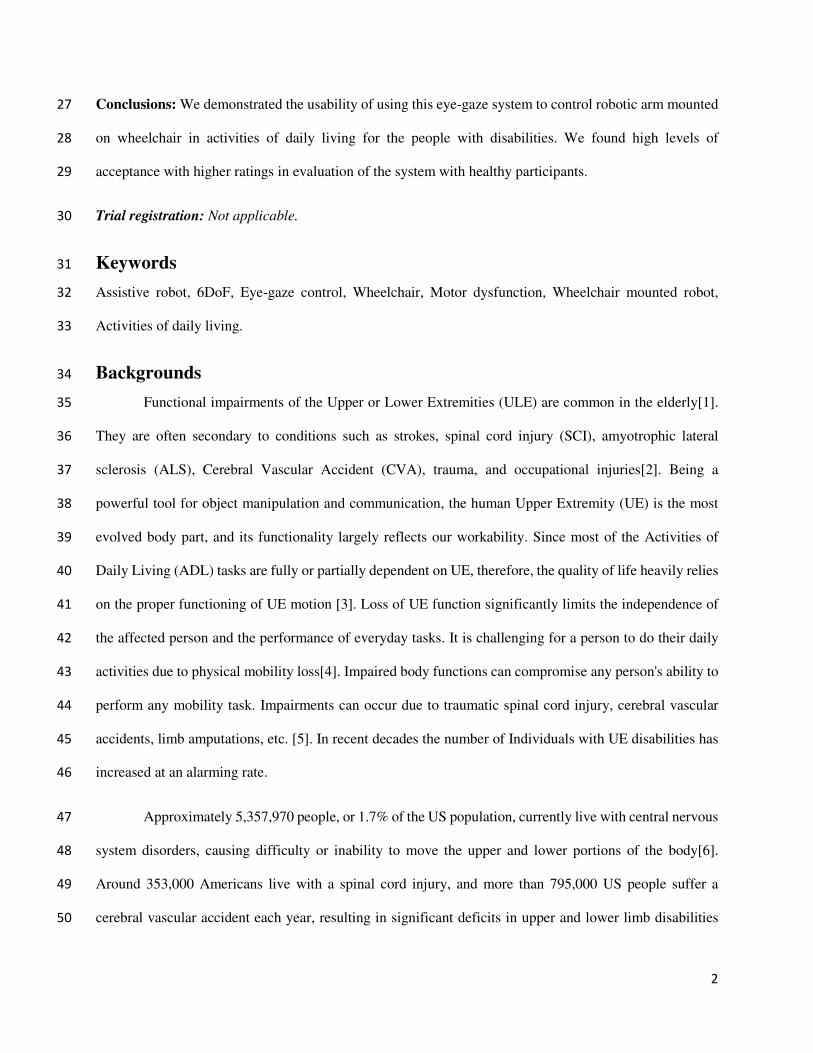
Abstract 14
Background: Building control architecture that balances the assistive manipulation systems with the 15
benefits of direct human control is a crucial challenge of human-robot collaboration. It promises to help 16
people with disabilities more efficiently control wheelchair and wheelchair-mounted robot arms to 17
accomplish activities of daily living. 18
Methods: In this paper, our research objective is to design an eye-tracking assistive robot control system 19
capable of providing targeted engagement and motivating individuals with a disability to use the developed 20
method for self-assistance activities of daily living. The graphical user interface is designed and integrated 21
with the developed control architecture to achieve the goal. 22
Results: We evaluated the system by conducting a user study. Ten healthy participants performed five trials 23
of three manipulation tasks using the graphical user interface and the developed control framework. The 24
100% success rate on task performance demonstrates the effectiveness of our system for individuals with 25
motor impairments to control wheelchair and wheelchair-mounted assistive robotic manipulators. 26
2
Conclusions: We demonstrated the usability of using this eye-gaze system to control robotic arm mounted 27
on wheelchair in activities of daily living for the people with disabilities. We found high levels of 28
acceptance with higher ratings in evaluation of the system with healthy participants. 29
Trial registration: Not applicable. 30
Keywords 31
Assistive robot, 6DoF, Eye-gaze control, Wheelchair, Motor dysfunction, Wheelchair mounted robot, 32
Activities of daily living. 33
Backgrounds 34
Functional impairments of the Upper or Lower Extremities (ULE) are common in the elderly[1]. 35
They are often secondary to conditions such as strokes, spinal cord injury (SCI), amyotrophic lateral 36
sclerosis (ALS), Cerebral Vascular Accident (CVA), trauma, and occupational injuries[2]. Being a 37
powerful tool for object manipulation and communication, the human Upper Extremity (UE) is the most 38
evolved body part, and its functionality largely reflects our workability. Since most of the Activities of 39
Daily Living (ADL) tasks are fully or partially dependent on UE, therefore, the quality of life heavily relies 40
on the proper functioning of UE motion [3]. Loss of UE function significantly limits the independence of 41
the affected person and the performance of everyday tasks. It is challenging for a person to do their daily 42
activities due to physical mobility loss[4]. Impaired body functions can compromise any person's ability to 43
perform any mobility task. Impairments can occur due to traumatic spinal cord injury, cerebral vascular 44
accidents, limb amputations, etc. [5]. In recent decades the number of Individuals with UE disabilities has 45
increased at an alarming rate. 46
Approximately 5,357,970 people, or 1.7% of the US population, currently live with central nervous 47
system disorders, causing difficulty or inability to move the upper and lower portions of the body[6]. 48
Around 353,000 Americans live with a spinal cord injury, and more than 795,000 US people suffer a 49
cerebral vascular accident each year, resulting in significant deficits in upper and lower limb disabilities 50
3
[6]. Among them, it is estimated that about two-thirds of cerebral vascular accident survivors suffer acute 51
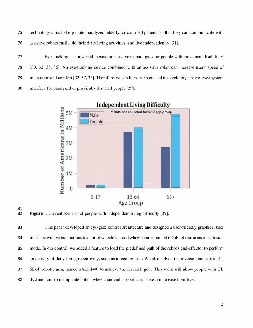
arm impairment[6, 7]. Figure 1 shows the current scenario of people with independent living difficulty[8]. 52
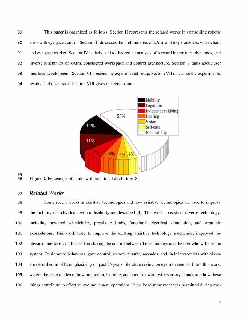
Figure 2 shows the percentage of adults with functional disabilities in the USA[8]. Loss of upper limb 53
function significantly limits the independence of the affected person and everyday tasks' performance—a 54
significant challenge for these people to do their daily activities without any external help. 55
Although a caregiver and assistive devices providing support for specific tasks, very few 56
individuals use disabled adapted facilities [9, 10]; however, such facilities have restricted their mobility. 57
IwULEDs (Individuals with upper/lower extremities dysfunctions) can be able to take care of themselves 58
without significant help from others[11]. Thus, research on Activities of daily living (ADL) and mobility 59
assistance targeting this specific population is an immense need to improve the independence of those 60
individuals and, therefore, to reduce the burden of care for the family. 61
Modern technologies help people with disabilities improve their quality of life and do their daily 62
activities using assistive robots/devices[12-15]. People with motor dysfunctionalities, different 63
neuromuscular diseases, and traumatic injuries face several problems in carrying out daily living activities 64
(ADL), including feeding, toileting, dressing, and bathing[16-20]. Usages of assistive technologies like a 65
powered wheelchair and robotic hand to assist these people are on the rise[4]. Working with assistive 66
technologies and upgrading them for better usage is becoming a newer trend [4] and caught the interest of 67
clinics, research, and industry[21]. Different types of research work are going on to improve assistive 68
technology [22-24]. In particular, assistive robotics appeared as an exciting research topic that can enhance 69
people's quality of life with motor dysfunctionalities. The earlier powered wheelchair was controlled with 70
a joystick [25-27], but people with musculoskeletal disease/injury resulting from stroke, spinal cord injury, 71
trauma, amyotrophic lateral sclerosis, etc. could not use the hand-controlled joystick [28]. That is the reason 72
why eye-gaze control has been explored [21, 29-34]. And researchers are improving the eye-gaze control 73
of an assistive robot to help these impaired people's daily activities. This eye-gaze control of assistive robot 74
4
technology aims to help mute, paralyzed, elderly, or confined patients so that they can communicate with 75
assistive robots easily, do their daily living activities, and live independently [31]. 76
Eye-tracking is a powerful means for assistive technologies for people with movement disabilities 77
[30, 32, 35, 36]. An eye-tracking device combined with an assistive robot can increase users' speed of 78
interaction and comfort [32, 37, 38]. Therefore, researchers are interested in developing an eye-gaze system 79
interface for paralyzed or physically disabled people [29]. 80
81
Figure 1. Current scenario of people with independent living difficulty [39]. 82
This paper developed an eye-gaze control architecture and designed a user-friendly graphical user 83
interface with virtual buttons to control wheelchair and wheelchair-mounted 6DoF robotic arms in cartesian 84
mode. In our control, we added a feature to load the predefined path of the robot's end-effector to perform 85
an activity of daily living repetitively, such as a feeding task. We also solved the inverse kinematics of a 86
6DoF robotic arm, named xArm [40] to achieve the research goal. This work will allow people with UE 87
dysfunctions to manipulate both a wheelchair and a robotic assistive arm to ease their lives. 88
5
This paper is organized as follows: Section II represents the related works in controlling robotic 89
arms with eye gaze control. Section III discusses the preliminaries of xArm and its parameters, wheelchair, 90
and eye gaze tracker. Section IV is dedicated to theoretical analysis of forward kinematics, dynamics, and 91
inverse kinematics of xArm, considered workspace and control architecture. Section V talks about user 92
interface development. Section VI presents the experimental setup. Section VII discusses the experiments, 93
results, and discussion. Section VIII gives the conclusion. 94
95
Figure 2. Percentage of adults with functional disabilities[8]. 96
Related Works 97
Some recent works in assistive technologies and how assistive technologies are used to improve 98
the mobility of individuals with a disability are described [4]. This work consists of diverse technology, 99
including powered wheelchairs, prosthetic limbs, functional electrical stimulation, and wearable 100
exoskeletons. This work tried to improve the existing assistive technology mechanics, improved the 101
physical interface, and focused on sharing the control between the technology and the user who will use the 102
system. Oculomotor behaviors, gaze control, smooth pursuit, saccades, and their interactions with vision 103
are described in [41], emphasizing on past 25 years' literature review on eye movements. From this work, 104
we got the general idea of how prediction, learning, and attention work with sensory signals and how these 105
things contribute to effective eye movement operations. If the head movement was permitted during eye-106
6
tracking, it isn't easy to track the eye movement. A simple eye gaze tracker-based interface controls the 107
wheelchair with free head movement described in [29]. A 3D orientation sensor is used in this eye-gaze 108
estimation system to measure the head position and orientation. In this way, a user can keep a comfortable 109
head pose or change head position while navigating the wheelchair. But the experimental result shows that 110
this system is a little bit slower than other keyboard-based navigation systems. 111
In [30], an eye-tracking-based telerobotic arm system is proposed for tele-writing and drawing. 112
Eight subjects were selected and trained for the experiment. This system's primary purpose is to use eye-113
tracking to operate a robotic arm and move the robotic arm with their gaze on a flat vertical screen for 114
writing the word with a pen attached with the arm at the endpoint. Authors in [31] describe using a low-115
cost gaze tracking hardware (Gazepoint GP3 Eye Tracker) to visually draw some shapes, used as input for 116
robot command. A custom algorithm and MATLAB are used to detect and process the command. A small 117
humanoid robot (NAO) is used for this experiment. The robot works as a personal assistant for impaired 118
people, and people can use an eye gaze tracking system to command the robot. An eye-tracking robotic 119
system for controlling a wheelchair and doing some daily living activities (ADL) using a wheelchair-120
mounted hand-exoskeleton is explored in [32]. The system is named EMOHEX, which can help people 121
with disabilities moving the wheelchair and also holding an object using the robotic arm. A graphical user 122
interface is developed in [33] to control the powered wheelchair. An eye tracker interacts with the system 123
and helps people with upper limb disabilities do their daily living activities. 124
The work in [34] describes an intelligent user interface designed with an eye-tracking system 125
named Display/Eye Tracker device Set (DETS). The system is based on the VHF+ algorithm. Using this 126
system, a wheelchair user can select a destination on a local map space, and after that, the wheelchair 127
automatically started to go to that destination point. The objective of this work [21] is to use low-cost 128
equipment and design a system where an assistive robotic arm can be used with the help of eye-tracking. 129
The research aimed so that individuals can afford the system and use the system to control the robotic arm 130
for reaching and grasping an object successfully. 131
7
Methods 132
Description of Materials 133
Robotic Arm 134
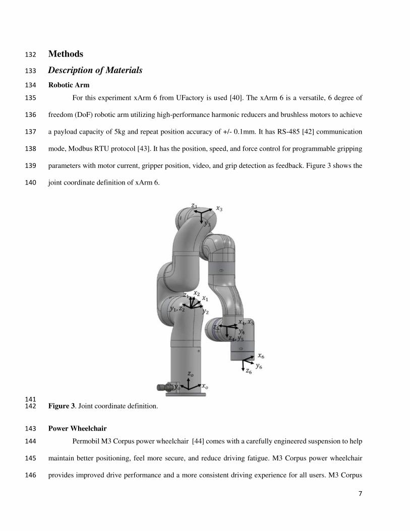
For this experiment xArm 6 from UFactory is used [40]. The xArm 6 is a versatile, 6 degree of 135
freedom (DoF) robotic arm utilizing high-performance harmonic reducers and brushless motors to achieve 136
a payload capacity of 5kg and repeat position accuracy of +/- 0.1mm. It has RS-485 [42] communication 137
mode, Modbus RTU protocol [43]. It has the position, speed, and force control for programmable gripping 138
parameters with motor current, gripper position, video, and grip detection as feedback. Figure 3 shows the 139
joint coordinate definition of xArm 6. 140
141
Figure 3. Joint coordinate definition. 142
Power Wheelchair 143
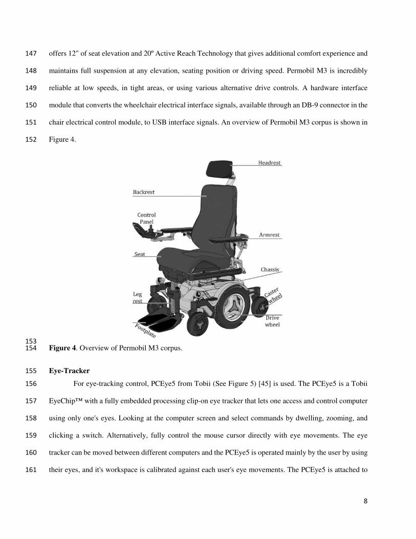
Permobil M3 Corpus power wheelchair [44] comes with a carefully engineered suspension to help 144
maintain better positioning, feel more secure, and reduce driving fatigue. M3 Corpus power wheelchair 145
provides improved drive performance and a more consistent driving experience for all users. M3 Corpus 146
8
offers 12" of seat elevation and 20º Active Reach Technology that gives additional comfort experience and 147
maintains full suspension at any elevation, seating position or driving speed. Permobil M3 is incredibly 148
reliable at low speeds, in tight areas, or using various alternative drive controls. A hardware interface 149
module that converts the wheelchair electrical interface signals, available through an DB-9 connector in the 150
chair electrical control module, to USB interface signals. An overview of Permobil M3 corpus is shown in 151
Figure 4. 152
153
Figure 4. Overview of Permobil M3 corpus. 154
Eye-Tracker 155
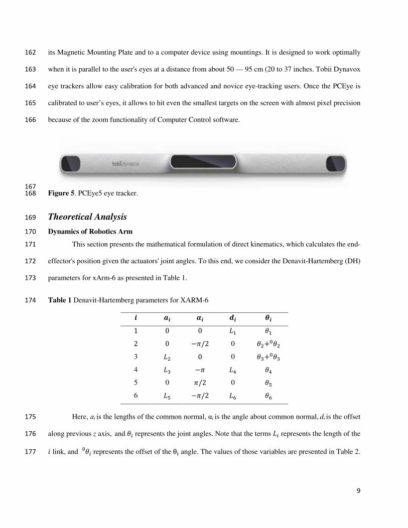
For eye-tracking control, PCEye5 from Tobii (See Figure 5) [45] is used. The PCEye5 is a Tobii 156
EyeChip™ with a fully embedded processing clip-on eye tracker that lets one access and control computer 157
using only one's eyes. Looking at the computer screen and select commands by dwelling, zooming, and 158
clicking a switch. Alternatively, fully control the mouse cursor directly with eye movements. The eye 159
tracker can be moved between different computers and the PCEye5 is operated mainly by the user by using 160
their eyes, and it's workspace is calibrated against each user's eye movements. The PCEye5 is attached to 161
9
its Magnetic Mounting Plate and to a computer device using mountings. It is designed to work optimally 162
when it is parallel to the user's eyes at a distance from about 50 — 95 cm (20 to 37 inches. Tobii Dynavox 163
eye trackers allow easy calibration for both advanced and novice eye-tracking users. Once the PCEye is 164
calibrated to user’s eyes, it allows to hit even the smallest targets on the screen with almost pixel precision 165
because of the zoom functionality of Computer Control software. 166
167
Figure 5. PCEye5 eye tracker. 168
Theoretical Analysis 169
Dynamics of Robotics Arm 170
This section presents the mathematical formulation of direct kinematics, which calculates the end-171
effector's position given the actuators' joint angles. To this end, we consider the Denavit-Hartemberg (DH) 172
parameters for xArm-6 as presented in Table 1. 173
Table 1 Denavit-Hartemberg parameters for XARM-6 174 𝜽𝒊𝒅𝒊𝜶𝒊𝒂𝒊𝒊 𝜃1𝐿1001 𝜃2+0𝜃20 −𝜋/202 𝜃3+0𝜃30 0𝐿23 𝜃4𝐿4−𝜋𝐿34 𝜃50 𝜋/20 5 𝜃6𝐿6−𝜋/2𝐿56
Here, ɑi is the lengths of the common normal, αi is the angle about common normal, di is the offset 175
along previous z axis, and 𝜃𝑖 represents the joint angles. Note that the terms 𝐿𝑖 represents the length of the 176 𝑖 link, and 𝜃𝑖0 represents the offset of the θi angle. The values of those variables are presented in Table 2. 177
10
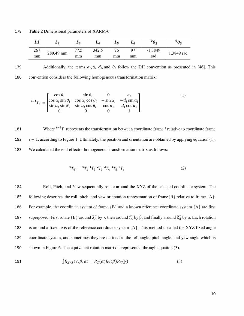
Table 2 Dimensional parameters of XARM-6 178 𝑳𝟏 𝑳𝟐 𝑳𝟑 𝑳𝟒 𝑳𝟓 𝑳𝟔 𝜽𝟐𝟎 𝜽𝟑𝟎267
mm 289.49 mm
77.5
mm
342.5
mm
76
mm
97
mm
-1.3849
rad 1.3849 rad
Additionally, the terms 𝑎𝑖,𝛼𝑖 ,𝑑𝑖, and 𝜃𝑖 follow the DH convention as presented in [46]. This 179
convention considers the following homogeneous transformation matrix: 180
𝑇𝑖𝑖−1 = [ cos𝜃𝑖 − sin𝜃𝑖 0 𝑎𝑖cos𝛼𝑖 sin𝜃𝑖 cos𝛼𝑖 cos𝜃𝑖 −sin𝛼𝑖 −𝑑𝑖 sin𝛼𝑖sin𝛼𝑖 sin𝜃𝑖 sin𝛼𝑖 cos𝜃𝑖 cos𝛼𝑖 𝑑𝑖 cos𝛼𝑖
0 0 0 1
] (1)
Where 𝑇𝑖𝑖−1 represents the transformation between coordinate frame 𝑖 relative to coordinate frame 181 𝑖 − 1, according to Figure 1. Ultimately, the position and orientation are obtained by applying equation (1). 182
We calculated the end-effector homogeneous transformation matrix as follows: 183
𝑇6 = 𝑇10 𝑇21 𝑇32 𝑇43 𝑇54 𝑇650 (2)
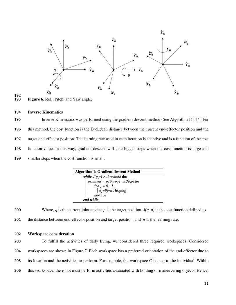
Roll, Pitch, and Yaw sequentially rotate around the XYZ of the selected coordinate system. The 184
following describes the roll, pitch, and yaw orientation representation of frame{B} relative to frame {A}: 185
For example, the coordinate system of frame {B} and a known reference coordinate system {A} are first 186
superposed. First rotate {B} around 𝑋𝐴 by γ, then around 𝑌𝐴 by β, and finally around 𝑍𝐴 by α. Each rotation 187
is around a fixed axis of the reference coordinate system {A}. This method is called the XYZ fixed angle 188
coordinate system, and sometimes they are defined as the roll angle, pitch angle, and yaw angle which is 189
shown in Figure 6. The equivalent rotation matrix is represented through equation (3). 190
𝑅𝑋𝑌𝑍(𝛾,𝛽,𝛼) = 𝑅𝑍(𝛼)𝑅𝑌(𝛽)𝑅𝑋(𝛾)𝐵𝐴 (3) 191
11
192
Figure 6. Roll, Pitch, and Yaw angle. 193
Inverse Kinematics 194
Inverse Kinematics was performed using the gradient descent method (See Algorithm 1) [47]. For 195
this method, the cost function is the Euclidean distance between the current end-effector position and the 196
target end-effector position. The learning rate used in each iteration is adaptive and is a function of the cost 197
function value. In this way, gradient descent will take bigger steps when the cost function is large and 198
smaller steps when the cost function is small. 199
Algorithm 1: Gradient Descent Method
while J(q,p) > threshold do:
gradient = 𝜕J𝜃,p𝜕q1…𝜕J𝜃,p𝜕qn
for j = 0…5:𝜃j=𝜃j−𝛼𝜕J𝜃,p𝜕qj end for
end while
Where, q is the current joint angles, p is the target position, J(q, p) is the cost function defined as 200
the distance between end-effector position and target position, and α is the learning rate. 201
Workspace consideration 202
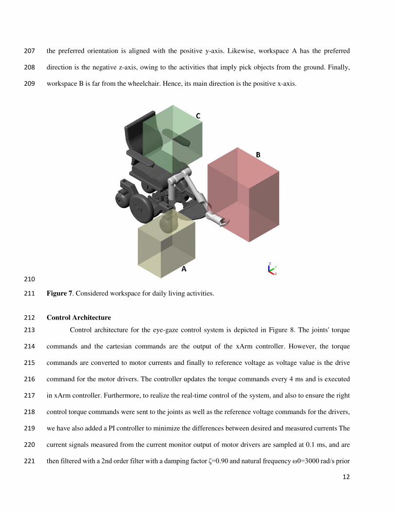
To fulfill the activities of daily living, we considered three required workspaces. Considered 203
workspaces are shown in Figure 7. Each workspace has a preferred orientation of the end-effector due to 204
its location and the activities to perform. For example, the workspace C is near to the individual. Within 205
this workspace, the robot must perform activities associated with holding or maneuvering objects. Hence, 206
12
the preferred orientation is aligned with the positive y-axis. Likewise, workspace A has the preferred 207
direction is the negative z-axis, owing to the activities that imply pick objects from the ground. Finally, 208
workspace B is far from the wheelchair. Hence, its main direction is the positive x-axis. 209
210
Figure 7. Considered workspace for daily living activities. 211
Control Architecture 212
Control architecture for the eye-gaze control system is depicted in Figure 8. The joints' torque 213
commands and the cartesian commands are the output of the xArm controller. However, the torque 214
commands are converted to motor currents and finally to reference voltage as voltage value is the drive 215
command for the motor drivers. The controller updates the torque commands every 4 ms and is executed 216
in xArm controller. Furthermore, to realize the real-time control of the system, and also to ensure the right 217
control torque commands were sent to the joints as well as the reference voltage commands for the drivers, 218
we have also added a PI controller to minimize the differences between desired and measured currents The 219
current signals measured from the current monitor output of motor drivers are sampled at 0.1 ms, and are 220
then filtered with a 2nd order filter with a damping factor ζ=0.90 and natural frequency ω0=3000 rad/s prior 221

13
to being sent to the PI controller. This control architecture includes combination of three types of control 222
loops: a position loop, a speed loop, and a current loop (See Figure 8). 223
The primary goal of the current loop is to control torque, which influences speed, and therefore, 224
position. The current loop is nested inside the speed loop, making current the innermost loop, with the speed 225
loop in the middle, and the position loop being the outermost loop. Current loop here is PI controllers, with 226
both proportional and integral gains. Current control parameters are set for tuning the current control loop. 227
On the other hand, the speed loop compares the commanded speed to the actual speed via an 228
encoder and issues commands to increase or decrease the motor's speed accordingly. The speed loop is also 229
a PI controller, with proportional gain and integral gain to determine the correction command. The amount 230
of proportional gain is directly proportional to the amount of the error, while the integral gain increases 231
over time and is used to "push" the motor to zero error at the end of the move. The position loop determines 232
the following error, which is the deviation between the actual and commanded positions, and issues speed 233
commands to reduce or eliminate the following error. In this cascaded system, the position loop used only 234
a proportional gain. 235
236
Figure 8. Control architecture of the system. 237
238
239
14
Graphical User Interface Development 240
User Interface is built with virtual buttons with python using PyQt5 and integrated with 241
multithreading, allowing sending the commands from virtual buttons to the controller simultaneously. For 242
better eye tracking, we used Tobii PCEye 5 hardware with their integrated software system. We used it with 243
the latest Microsoft Surface Pro 7, mounted with wheelchair-using mounting brackets. We are using 244
computer control software for tracking eye movement and operate the computer. For better performance, 245
we have to calibrate it first. Then we use the gaze control cursor for the left mouse button click, which 246
works both in dual time and continuous mode. 247
At first, we started using our system with a user interface, where we faced some issues. The issues 248
are too many buttons, small button size for triggering with eye gaze control, and the interface's complexity. 249
After that, we updated our graphical user interface, which is much simpler and easier to understand for 250
everyone. We have created a graphical user interface for interacting with the wheelchair and xArm. In 251
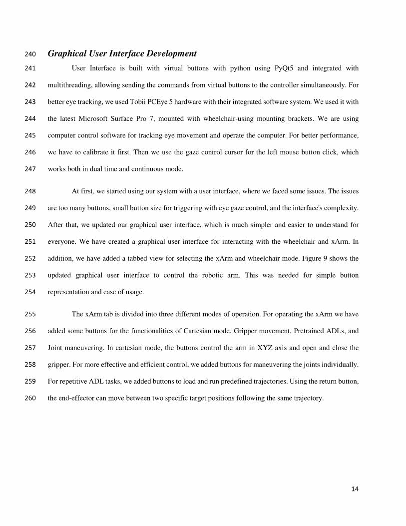
addition, we have added a tabbed view for selecting the xArm and wheelchair mode. Figure 9 shows the 252
updated graphical user interface to control the robotic arm. This was needed for simple button 253
representation and ease of usage. 254
The xArm tab is divided into three different modes of operation. For operating the xArm we have 255
added some buttons for the functionalities of Cartesian mode, Gripper movement, Pretrained ADLs, and 256
Joint maneuvering. In cartesian mode, the buttons control the arm in XYZ axis and open and close the 257
gripper. For more effective and efficient control, we added buttons for maneuvering the joints individually. 258
For repetitive ADL tasks, we added buttons to load and run predefined trajectories. Using the return button, 259
the end-effector can move between two specific target positions following the same trajectory. 260
15
261
Figure 9. Graphical user interface for robotic arm control. 262
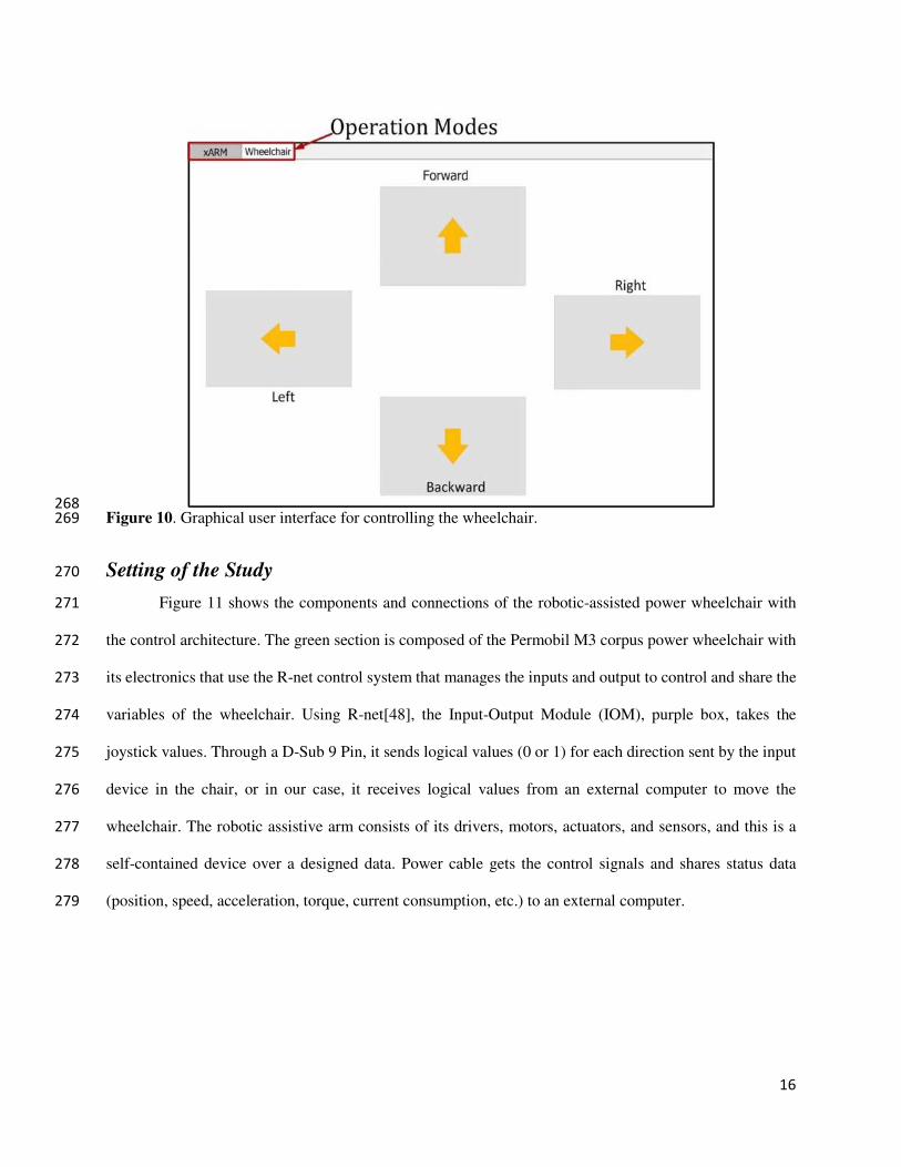
Again, for moving the wheelchair, we have added virtual buttons. In wheelchair tab of the interface 263
four buttons are placed which is triggered through left mouse click and this click is done through eye gaze 264
dwell time. If the mouse cursor is on the button after the dwell time wheelchair will go in that specific 265
direction and the wheelchair will stop if the cursor moves out from the button. Figure 10 shows the user 266
interface for controlling the wheelchair using eye gaze control. 267
16
268
Figure 10. Graphical user interface for controlling the wheelchair. 269
Setting of the Study 270
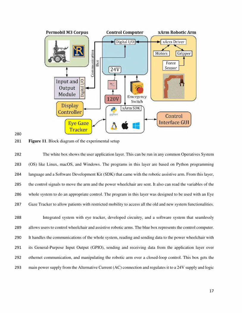
Figure 11 shows the components and connections of the robotic-assisted power wheelchair with 271
the control architecture. The green section is composed of the Permobil M3 corpus power wheelchair with 272
its electronics that use the R-net control system that manages the inputs and output to control and share the 273
variables of the wheelchair. Using R-net[48], the Input-Output Module (IOM), purple box, takes the 274
joystick values. Through a D-Sub 9 Pin, it sends logical values (0 or 1) for each direction sent by the input 275
device in the chair, or in our case, it receives logical values from an external computer to move the 276
wheelchair. The robotic assistive arm consists of its drivers, motors, actuators, and sensors, and this is a 277
self-contained device over a designed data. Power cable gets the control signals and shares status data 278
(position, speed, acceleration, torque, current consumption, etc.) to an external computer. 279
17
280
Figure 11. Block diagram of the experimental setup 281
The white box shows the user application layer. This can be run in any common Operatives System 282
(OS) like Linux, macOS, and Windows. The programs in this layer are based on Python programming 283
language and a Software Development Kit (SDK) that came with the robotic assistive arm. From this layer, 284
the control signals to move the arm and the power wheelchair are sent. It also can read the variables of the 285
whole system to do an appropriate control. The program in this layer was designed to be used with an Eye 286
Gaze Tracker to allow patients with restricted mobility to access all the old and new system functionalities. 287
Integrated system with eye tracker, developed circuitry, and a software system that seamlessly 288
allows users to control wheelchair and assistive robotic arms. The blue box represents the control computer. 289
It handles the communications of the whole system, reading and sending data to the power wheelchair with 290
its General-Purpose Input Output (GPIO), sending and receiving data from the application layer over 291
ethernet communication, and manipulating the robotic arm over a closed-loop control. This box gets the 292
main power supply from the Alternative Current (AC) connection and regulates it to a 24V supply and logic 293
18
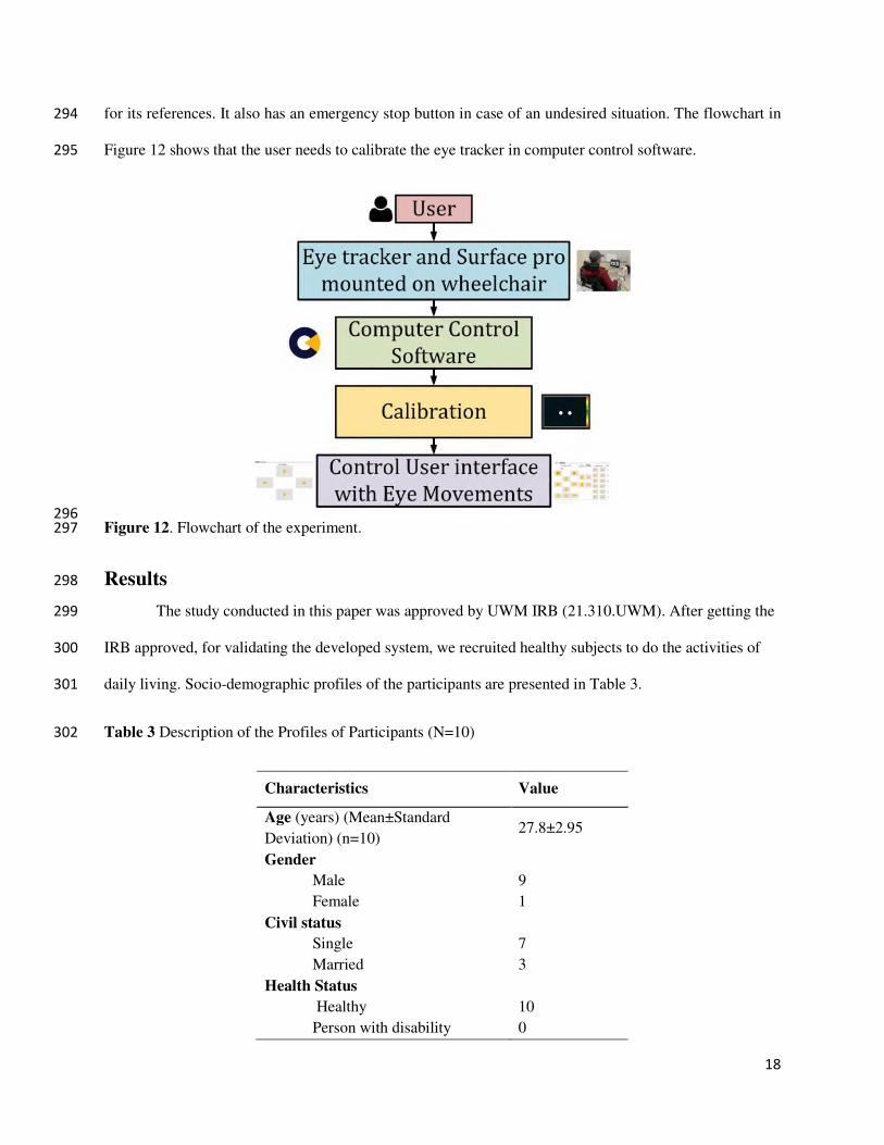
for its references. It also has an emergency stop button in case of an undesired situation. The flowchart in 294
Figure 12 shows that the user needs to calibrate the eye tracker in computer control software. 295
296
Figure 12. Flowchart of the experiment. 297
Results 298
The study conducted in this paper was approved by UWM IRB (21.310.UWM). After getting the 299
IRB approved, for validating the developed system, we recruited healthy subjects to do the activities of 300
daily living. Socio-demographic profiles of the participants are presented in Table 3. 301
Table 3 Description of the Profiles of Participants (N=10) 302
Characteristics Value
Age (years) (Mean±Standard
Deviation) (n=10) 27.8±2.95
Gender
Male 9
Female 1
Civil status
Single 7
Married 3
Health Status
Healthy 10
Person with disability 0
19
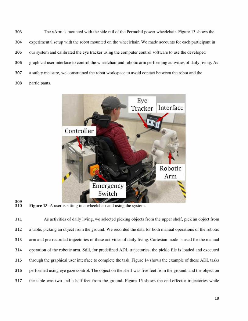
The xArm is mounted with the side rail of the Permobil power wheelchair. Figure 13 shows the 303
experimental setup with the robot mounted on the wheelchair. We made accounts for each participant in 304
our system and calibrated the eye tracker using the computer control software to use the developed 305
graphical user interface to control the wheelchair and robotic arm performing activities of daily living. As 306
a safety measure, we constrained the robot workspace to avoid contact between the robot and the 307
participants. 308
309
Figure 13. A user is sitting in a wheelchair and using the system. 310
As activities of daily living, we selected picking objects from the upper shelf, pick an object from 311
a table, picking an object from the ground. We recorded the data for both manual operations of the robotic 312
arm and pre-recorded trajectories of these activities of daily living. Cartesian mode is used for the manual 313
operation of the robotic arm. Still, for predefined ADL trajectories, the pickle file is loaded and executed 314
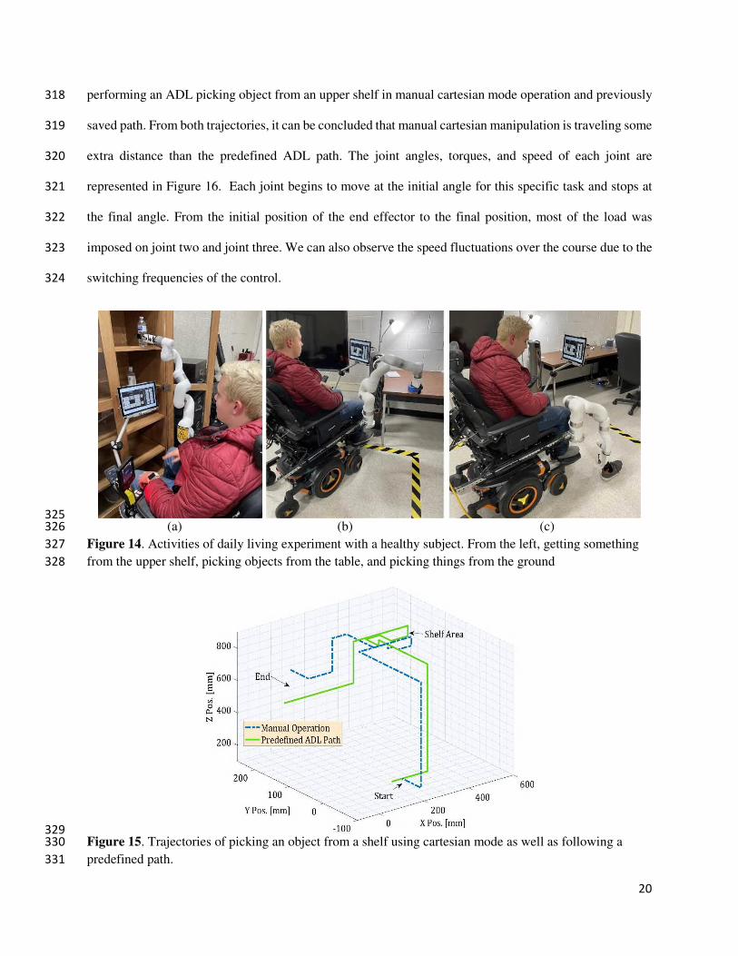
through the graphical user interface to complete the task. Figure 14 shows the example of these ADL tasks 315
performed using eye gaze control. The object on the shelf was five feet from the ground, and the object on 316
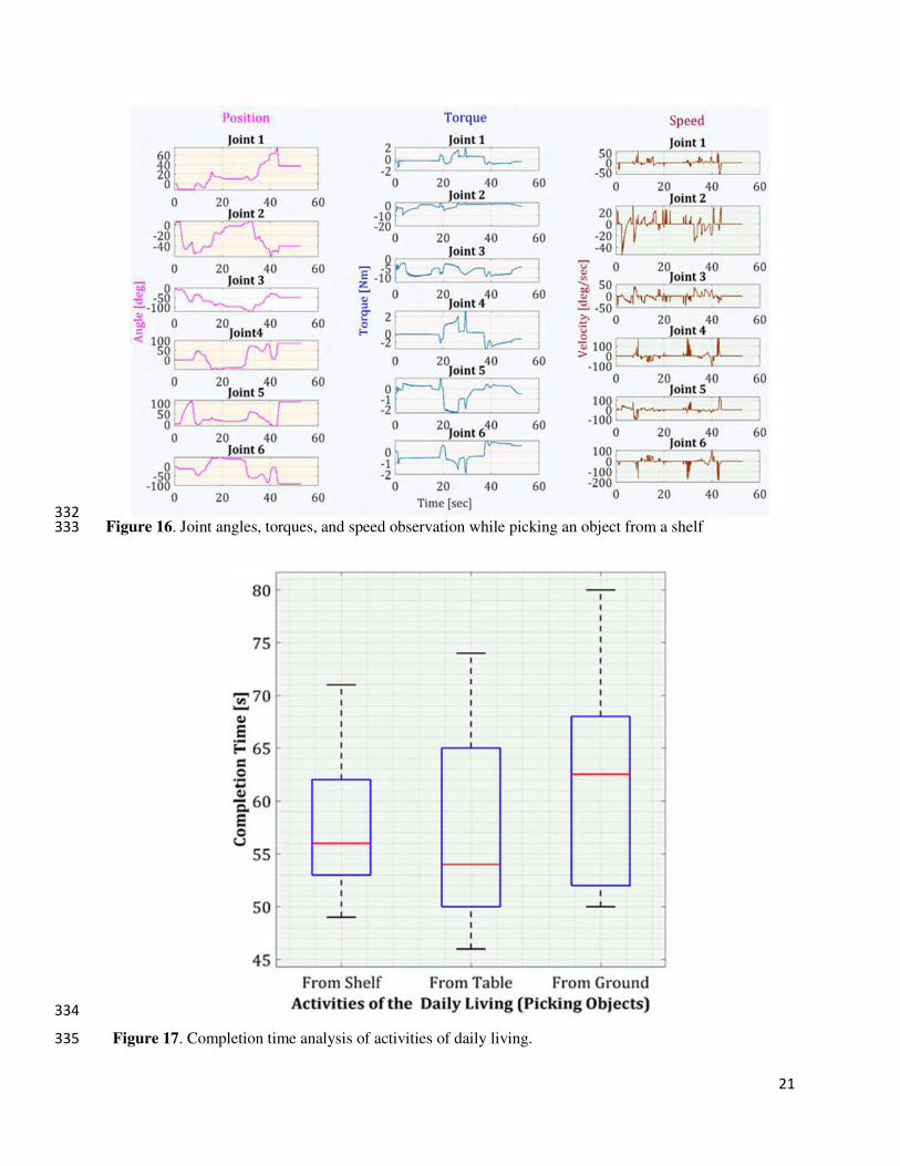
the table was two and a half feet from the ground. Figure 15 shows the end-effector trajectories while 317
20
performing an ADL picking object from an upper shelf in manual cartesian mode operation and previously 318
saved path. From both trajectories, it can be concluded that manual cartesian manipulation is traveling some 319
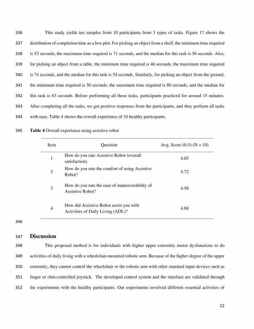
extra distance than the predefined ADL path. The joint angles, torques, and speed of each joint are 320
represented in Figure 16. Each joint begins to move at the initial angle for this specific task and stops at 321
the final angle. From the initial position of the end effector to the final position, most of the load was 322
imposed on joint two and joint three. We can also observe the speed fluctuations over the course due to the 323
switching frequencies of the control. 324
325
(a) (b) (c) 326
Figure 14. Activities of daily living experiment with a healthy subject. From the left, getting something 327
from the upper shelf, picking objects from the table, and picking things from the ground 328
329
Figure 15. Trajectories of picking an object from a shelf using cartesian mode as well as following a 330
predefined path. 331
21
332
Figure 16. Joint angles, torques, and speed observation while picking an object from a shelf 333
334
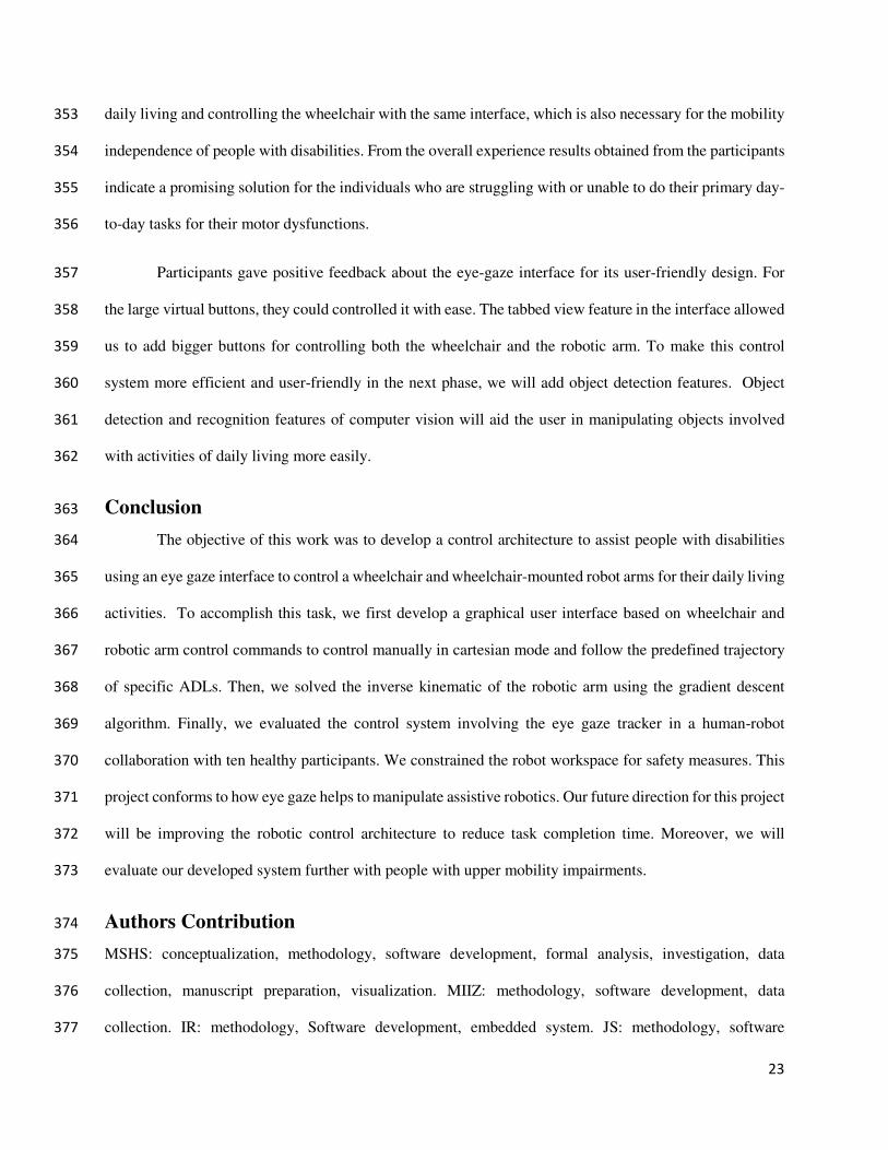
Figure 17. Completion time analysis of activities of daily living. 335
22
This study yields ten samples from 10 participants from 3 types of tasks. Figure 17 shows the 336
distribution of completion time as a box plot. For picking an object from a shelf, the minimum time required 337
is 53 seconds, the maximum time required is 71 seconds, and the median for this task is 56 seconds. Also, 338
for picking an object from a table, the minimum time required is 46 seconds, the maximum time required 339
is 74 seconds, and the median for this task is 54 seconds. Similarly, for picking an object from the ground, 340
the minimum time required is 50 seconds, the maximum time required is 80 seconds, and the median for 341
this task is 63 seconds. Before performing all these tasks, participants practiced for around 15 minutes. 342
After completing all the tasks, we got positive responses from the participants, and they perform all tasks 343
with ease. Table 4 shows the overall experience of 10 healthy participants. 344
Table 4 Overall experience using assistive robot 345
Item Question Avg. Score (0-5) (N = 10)
1 How do you rate Assistive Robot (overall
satisfaction) 4.65
2 How do you rate the comfort of using Assistive
Robot? 4.72
3 How do you rate the ease of maneuverability of
Assistive Robot? 4.58
4 How did Assistive Robot assist you with
Activities of Daily Living (ADL)? 4.88
346
Discussion 347
This proposed method is for individuals with higher upper extremity motor dysfunctions to do 348
activities of daily living with a wheelchair-mounted robotic arm. Because of the higher degree of the upper 349
extremity, they cannot control the wheelchair or the robotic arm with other standard input devices such as 350
finger or chin-controlled joystick. The developed control system and the interface are validated through 351
the experiments with the healthy participants. Our experiments involved different essential activities of 352
23
daily living and controlling the wheelchair with the same interface, which is also necessary for the mobility 353
independence of people with disabilities. From the overall experience results obtained from the participants 354
indicate a promising solution for the individuals who are struggling with or unable to do their primary day-355
to-day tasks for their motor dysfunctions. 356
Participants gave positive feedback about the eye-gaze interface for its user-friendly design. For 357
the large virtual buttons, they could controlled it with ease. The tabbed view feature in the interface allowed 358
us to add bigger buttons for controlling both the wheelchair and the robotic arm. To make this control 359
system more efficient and user-friendly in the next phase, we will add object detection features. Object 360
detection and recognition features of computer vision will aid the user in manipulating objects involved 361
with activities of daily living more easily. 362
Conclusion 363
The objective of this work was to develop a control architecture to assist people with disabilities 364
using an eye gaze interface to control a wheelchair and wheelchair-mounted robot arms for their daily living 365
activities. To accomplish this task, we first develop a graphical user interface based on wheelchair and 366
robotic arm control commands to control manually in cartesian mode and follow the predefined trajectory 367
of specific ADLs. Then, we solved the inverse kinematic of the robotic arm using the gradient descent 368
algorithm. Finally, we evaluated the control system involving the eye gaze tracker in a human-robot 369
collaboration with ten healthy participants. We constrained the robot workspace for safety measures. This 370
project conforms to how eye gaze helps to manipulate assistive robotics. Our future direction for this project 371
will be improving the robotic control architecture to reduce task completion time. Moreover, we will 372
evaluate our developed system further with people with upper mobility impairments. 373
Authors Contribution 374
MSHS: conceptualization, methodology, software development, formal analysis, investigation, data 375
collection, manuscript preparation, visualization. MIIZ: methodology, software development, data 376
collection. IR: methodology, Software development, embedded system. JS: methodology, software 377
24
development. MHR: methodology, investigation, supervision, project administration, funding acquisition, 378
writing—review and editing. SIA: resources, writing—review and editing, supervision, funding 379
acquisition. IW: data analysis, funding acquisition, writing—review and editing. KS: data analysis, 380
writing—review and editing. BB: control method analysis, writing—review and editing. All authors read 381
and approved the final manuscript. 382
Declarations 383
Ethics approval and consent to participate 384
The study conducted in this manuscript was approved by UWM IRB (21.310.UWM) and 385
participants gave their consent to participate. 386
Consent for publications 387
We got the consent of the participants’ as per the protocol of UWM IRB (21.310.UWM).388
Availability of data and material 389
The datasets generated during and/or analyzed during the current study are not publicly available 390
due to the conditions of the funding source but are available from the corresponding author on reasonable 391
request. 392
Competing interests 393
The authors declare that they have no competing interests. 394
Funding 395
This work was supported by the Disability and Rehabilitation Research Projects (DRRP) Program, 396
National Institute on Disability, Independent Living, and Rehabilitation Research, Department of Health 397
and Human Services, Award # 90DPGE0018-02-00. 398
Acknowledgement 399
Not Applicable. 400
Disclaimer 401
The contents do not represent the views of the U.S. Department of Veterans Affairs or the United 402
States Government. 403
25
References 404
[1] M. A. Minetto, A. Giannini, R. McConnell, C. Busso, G. Torre, and G. Massazza, “Common 405
Musculoskeletal Disorders in the Elderly: The Star Triad,” Journal of clinical medicine, vol. 9, 406
no. 4, pp. 1216, 2020. 407
[2] A. C. McKee, and D. H. Daneshvar, “The neuropathology of traumatic brain injury,” Handbook 408
of clinical neurology, vol. 127, pp. 45-66, 2015. 409
[3] M. E. Mlinac, and M. C. Feng, “Assessment of Activities of Daily Living, Self-Care, and 410
Independence,” Archives of Clinical Neuropsychology, vol. 31, no. 6, pp. 506-516, 2016. 411
[4] R. E. Cowan, B. J. Fregly, M. L. Boninger, L. Chan, M. M. Rodgers, and D. J. Reinkensmeyer, 412
“Recent trends in assistive technology for mobility,” Journal of neuroengineering and 413
rehabilitation, vol. 9, no. 1, pp. 1-8, 2012. 414
[5] A. Alizadeh, S. M. Dyck, and S. Karimi-Abdolrezaee, “Traumatic Spinal Cord Injury: An 415
Overview of Pathophysiology, Models and Acute Injury Mechanisms,” Frontiers in neurology,416
vol. 10, pp. 282-282, 2019. 417
[6] M. Wyndaele, and J.-J. Wyndaele, “Incidence, prevalence and epidemiology of spinal cord 418
injury: what learns a worldwide literature survey?,” Spinal cord, vol. 44, no. 9, pp. 523-529, 419
2006. 420
[7] J. Mackay, and G. A. Mensah, The atlas of heart disease and stroke: World Health Organization, 421
2004. 422
[8] "Disability Impacts All of Us Infographic | CDC," 2021; 423
https://www.cdc.gov/ncbddd/disabilityandhealth/infographic-disability-impacts-all.html. 424
[9] J. H. Rimmer, S. Padalabalanarayanan, L. A. Malone, and T. Mehta, “Fitness facilities still lack 425
accessibility for people with disabilities,” Disability and Health Journal, vol. 10, no. 2, pp. 214-426
221, 2017/04/01/, 2017. 427
26
[10] G. L. Krahn, D. K. Walker, and R. Correa-De-Araujo, “Persons with disabilities as an 428
unrecognized health disparity population,” American journal of public health, vol. 105 Suppl 2, 429
no. Suppl 2, pp. S198-S206, 2015. 430
[11] A. R. Darragh, C. M. Sommerich, S. A. Lavender, K. J. Tanner, K. Vogel, and M. Campo, 431
“Musculoskeletal Discomfort, Physical Demand, and Caregiving Activities in Informal 432
Caregivers,” Journal of applied gerontology : the official journal of the Southern Gerontological 433
Society, vol. 34, no. 6, pp. 734-760, 2015. 434
[12] A.-M. Hughes, J. H. Burridge, S. H. Demain, C. Ellis-Hill, C. Meagher, L. Tedesco-Triccas, R. 435
Turk, and I. Swain, “Translation of evidence-based assistive technologies into stroke 436
rehabilitation: users’ perceptions of the barriers and opportunities,” BMC health services 437
research, vol. 14, no. 1, pp. 1-12, 2014. 438
[13] S. Mohammed, Y. Amirat, and H. Rifai, “Lower-limb movement assistance through wearable 439
robots: State of the art and challenges,” Advanced Robotics, vol. 26, no. 1-2, pp. 1-22, 2012. 440
[14] Z. H. Khan, A. Siddique, and C. W. Lee, “Robotics utilization for healthcare digitization in global 441
COVID-19 management,” International journal of environmental research and public health,442
vol. 17, no. 11, pp. 3819, 2020. 443
[15] E. Martinez-Martin, M. Cazorla, and S. Orts-Escolano, "Machine Learning Techniques for 444
Assistive Robotics," Multidisciplinary Digital Publishing Institute, 2020. 445
[16] A. J. Skalsky, and C. M. McDonald, “Prevention and management of limb contractures in 446
neuromuscular diseases,” Physical Medicine and Rehabilitation Clinics, vol. 23, no. 3, pp. 675-447
687, 2012. 448
[17] A. Crawford, H. H. Hollingsworth, K. Morgan, and D. B. Gray, “People with mobility 449
impairments: Physical activity and quality of participation,” Disability and health journal, vol. 1, 450
no. 1, pp. 7-13, 2008. 451
[18] N. I. Ibrahim, M. S. Ahmad, M. S. Zulfarina, S. N. A. S. M. Zaris, I. N. Mohamed, N. Mohamed, 452
S. A. Mokhtar, and A. N. Shuid, “Activities of daily living and determinant factors among older 453
27
adult subjects with lower body fracture after discharge from hospital: a prospective study,” 454
International journal of environmental research and public health, vol. 15, no. 5, pp. 1002, 2018. 455
[19] F. Cordella, A. L. Ciancio, R. Sacchetti, A. Davalli, A. G. Cutti, E. Guglielmelli, and L. Zollo, 456
“Literature review on needs of upper limb prosthesis users,” Frontiers in neuroscience, vol. 10, 457
pp. 209, 2016. 458
[20] I. M. Pires, N. M. Garcia, N. Pombo, and F. Flórez-Revuelta, “From data acquisition to data 459
fusion: a comprehensive review and a roadmap for the identification of activities of daily living 460
using mobile devices,” Sensors, vol. 16, no. 2, pp. 184, 2016. 461
[21] Y.-S. L.-K. Cio, M. Raison, C. L. Ménard, and S. Achiche, “Proof of concept of an assistive 462
robotic arm control using artificial stereovision and eye-tracking,” IEEE Transactions on Neural 463
Systems and Rehabilitation Engineering, vol. 27, no. 12, pp. 2344-2352, 2019. 464
[22] T. A. Valk, L. J. Mouton, E. Otten, and R. M. Bongers, “Fixed muscle synergies and their 465
potential to improve the intuitive control of myoelectric assistive technology for upper 466
extremities,” Journal of neuroengineering and rehabilitation, vol. 16, no. 1, pp. 1-20, 2019. 467
[23] V. Tangcharoensathien, W. Witthayapipopsakul, S. Viriyathorn, and W. Patcharanarumol, 468
“Improving access to assistive technologies: challenges and solutions in low-and middle-income 469
countries,” WHO South-East Asia journal of public health, vol. 7, no. 2, pp. 84, 2018. 470
[24] M. L. Toro-Hernández, P. Kankipati, M. Goldberg, S. Contepomi, D. R. Tsukimoto, and N. Bray, 471
“Appropriate assistive technology for developing countries,” Physical Medicine and 472
Rehabilitation Clinics, vol. 30, no. 4, pp. 847-865, 2019. 473
[25] S. Desai, S. Mantha, and V. Phalle, "Advances in smart wheelchair technology." pp. 1-7. 474
[26] E. B. Thorp, F. Abdollahi, D. Chen, A. Farshchiansadegh, M.-H. Lee, J. P. Pedersen, C. Pierella, 475
E. J. Roth, I. S. Gonzáles, and F. A. Mussa-Ivaldi, “Upper body-based power wheelchair control 476
interface for individuals with tetraplegia,” IEEE transactions on neural systems and 477
rehabilitation engineering, vol. 24, no. 2, pp. 249-260, 2015. 478
28
[27] N. Pellegrini, B. Guillon, H. Prigent, M. Pellegrini, D. Orlikovski, J.-C. Raphael, and F. Lofaso, 479
“Optimization of power wheelchair control for patients with severe Duchenne muscular 480
dystrophy,” Neuromuscular Disorders, vol. 14, no. 5, pp. 297-300, 2004. 481
[28] C.-S. Lin, C.-W. Ho, W.-C. Chen, C.-C. Chiu, and M.-S. Yeh, “Powered wheelchair controlled 482
by eye-tracking system,” Optica Applicata, vol. 36, 2006. 483
[29] Q. X. Nguyen, and S. Jo, “Electric wheelchair control using head pose free eye-gaze tracker,” 484
Electronics Letters, vol. 48, no. 13, pp. 750-752, 2012. 485
[30] S. Dziemian, W. W. Abbott, and A. A. Faisal, "Gaze-based teleprosthetic enables intuitive 486
continuous control of complex robot arm use: Writing & drawing." pp. 1277-1282. 487
[31] T. L. Craig, C. A. Nelson, S. Li, and X. Zhang, "Human gaze commands classification: A shape 488
based approach to interfacing with robots." pp. 1-6. 489
[32] Y. K. Meena, A. Chowdhury, H. Cecotti, K. Wong-Lin, S. S. Nishad, A. Dutta, and G. Prasad, 490
"Emohex: An eye tracker based mobility and hand exoskeleton device for assisting disabled 491
people." pp. 002122-002127. 492
[33] Y. K. Meena, H. Cecotti, K. Wong-Lin, and G. Prasad, "A multimodal interface to resolve the 493
Midas-Touch problem in gaze controlled wheelchair." pp. 905-908. 494
[34] D. Cojocaru, L. F. Manta, I. C. Vladu, A. Dragomir, and A. M. Mariniuc, "Using an eye gaze new 495
combined approach to control a wheelchair movement." pp. 626-631. 496
[35] C.-S. Hwang, H.-H. Weng, L.-F. Wang, C.-H. Tsai, and H.-T. Chang, “An eye-tracking assistive 497
device improves the quality of life for ALS patients and reduces the caregivers’ burden,” Journal 498
of motor behavior, vol. 46, no. 4, pp. 233-238, 2014. 499
[36] X. Zhang, X. Liu, S.-M. Yuan, and S.-F. Lin, “Eye tracking based control system for natural 500
human-computer interaction,” Computational intelligence and neuroscience, vol. 2017, 2017. 501
[37] P. Biswas, and P. Langdon, “Multimodal intelligent eye-gaze tracking system,” International 502
Journal of Human-Computer Interaction, vol. 31, no. 4, pp. 277-294, 2015. 503
29
[38] Y. K. Meena, H. Cecotti, K. Wong-Lin, and G. Prasad, "Powered wheelchair control with a 504
multimodal interface using eye-tracking and soft-switch." p. 1. 505
[39] D. M. Taylor, “Americans with disabilities: 2014,” US Census Bureau, pp. 1-32, 2018. 506
[40] "UFACTORY xArm 6," https://www.ufactory.cc/products/xarm-6-2020. 507
[41] E. Kowler, “Eye movements: The past 25 years,” Vision research, vol. 51, no. 13, pp. 1457-1483, 508
2011. 509
[42] L. Geng, P. Wang, C. Ma, and H. Jia, “Design and implement of RS485 high speed data 510
communications protocol [J],” Journal of Tsinghua University (Science and Technology), vol. 8, 511
2008. 512
[43] D.-g. Peng, H. Zhang, L. Yang, and H. Li, "Design and realization of modbus protocol based on 513
embedded linux system." pp. 275-280. 514
[44] Permobil. "M3 Corpus," https://www.permobil.com/en-us/products/power-wheelchairs/permobil-515
m3-corpus. 516
[45] T. Dynavox. "PCEye," https://www.tobiidynavox.com/devices/eye-gaze-devices/pceye-5-517
31ad2875/?MarketPopupClicked=true. 518
[46] P. J. McKerrow, “Echolocation—from range to outline segments,” Robotics and Autonomous 519
systems, vol. 11, no. 3-4, pp. 205-211, 1993. 520
[47] S. Ruder, “An overview of gradient descent optimization algorithms,” arXiv preprint 521
arXiv:1609.04747, 2016. 522
[48] S. S. Al‐Wakeel, and M. Ilyas, “R‐net: A high speed fibre optics network with reservation access 523
protocol,” International Journal of Digital & Analog Communication Systems, vol. 5, no. 1, pp. 524
1-13, 1992. 525
526
Related Documents