MODEL RAILROADING WITH ARDUINO 2 John Plocher & David Falkenburg Silicon Valley Lines Model Railroad Club EXTRA 2011 WEST Digital Freight Warehouse Sunday, July 3, 2011 Model Railroading with Arduino 2 Hello, my name is John Plocher and I''m a member of the Silicon Valley Lines Model Railroad club in San Jose. I model modern day Union Pacific, Southern Pacific, Ace and CalTrain in the South Bay, though I seem to spend most of my time tinkering with electronics...

Welcome message from author
This document is posted to help you gain knowledge. Please leave a comment to let me know what you think about it! Share it to your friends and learn new things together.
Transcript

MODEL RAILROADING
WITH ARDUINO2
John Plocher & David Falkenburg
Silicon Valley Lines Model Railroad Club
EXTRA 2011 WEST
Digital Freight Warehouse
Sunday, July 3, 2011Model Railroading with Arduino 2
Hello, my name is John Plocher and I''m a member of the Silicon Valley Lines Model Railroad club in San Jose.
I model modern day Union Pacific, Southern Pacific, Ace and CalTrain in the South Bay, though I seem to spend most of my time tinkering with electronics...
THIS CLINIC IS FOR YOU, IF...
• The underside of your layout gets more of your attention than does your track and scenery
• You ever wanted to make your layout do something fun, different or complicated, but didn’t know where to start.
• You think “like the prototype” should apply to layout wiring and control, too
DIYSunday, July 3, 2011If you are like me, •! you find yourself working under your layout more than on top,•! you are less than satisfied by the complexity of the wiring, panels and control software you need to run your layout,•! you have an itch to add automation, animation and interactive "fun" to your model empire, and CLICK (DIY)•! you like to do it yourself.
This clinic is an overview of what I've done with Arduino micro-controllers, an introduction to "electronics tinkering" and - hopefully - an inspiration for you to try something yourself.

Railfan
Demos
Layout Tour
Basic concepts and examples
Cab ride
Control Points & cTc
TIME TABLE
Sunday, July 3, 2011
In the unconventional spirit of the week, this clinic was supposed to ! take you railfanning, see some layout tours and go on!a cab ride, but all I could fit into an hour slot was ! some demos, examples, and a simple cTc & control point simulation ...
If this sounds like fun, then: All aboard!

DEMOS & EXAMPLESTO GET YOUR IDEAS
FLOWING
• Lights and LEDs
• Servos
• Loconet Gadgets
Sunday, July 3, 2011
In the Introduction to Arduino clinic that Dave just gave, we learned what 'duinos were and how they work. While it may be a bit overkill to use a $30 micro-controller to flash a single LED, blinking lights make it easy to understand what is happening.
My wife still refers to my projects as "playing with blinking lights"
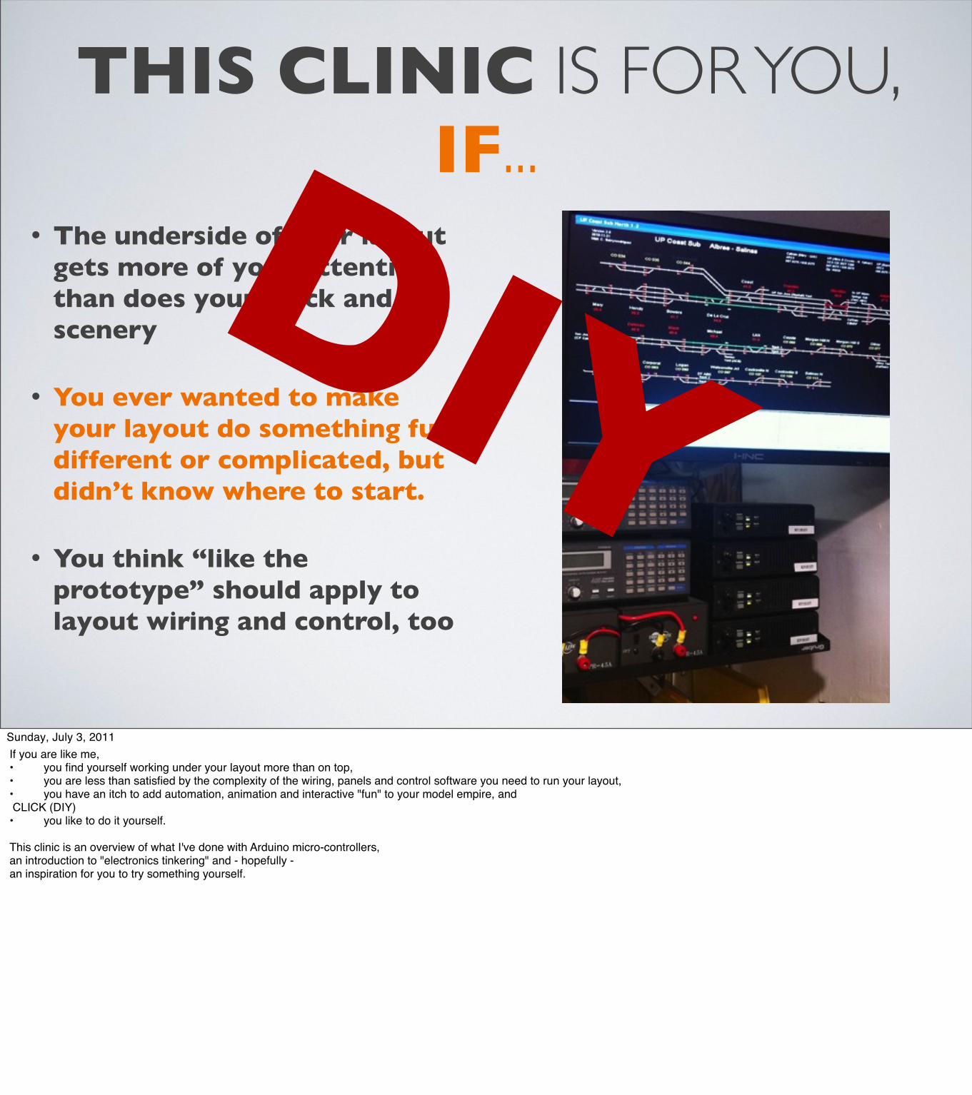
DANGERSHIELDAn Arduino add-on.
It's got a variety of electronic components that you can use to do fun and useful things:
A excuse to learn by playing!
linear sliders
temperature & light sensors
pushbuttons
buzzer
LEDs (of course!)
Sunday, July 3, 2011
My first project was building a "DangerShield" kit from the MakerSHED (Pass around demo)As a shield, it plugs into an Arduino, making something like a sandwich. The 'duino provides all the computing power, the shield, all the inputs and outputs. CLICK (parts ID)The DangerShield board uses all of the I/O ports on the Arduino, and is really intended to be a learning tool for how to interface with things. The "take away" for me from this project was that it is extremely easy to interact with the real world through simple sensors and devices.
Before I go on, a bit on Shields. A shield is a board that plugs into an Arduino, for example, this Ethernet interface or this motor controller.
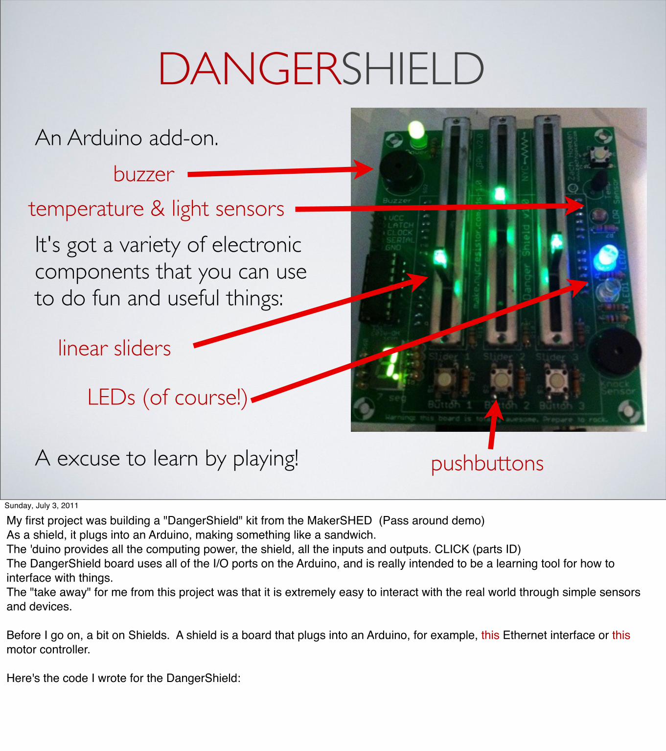
Here's the code I wrote for the DangerShield:
DANGER SHIELD SKETCH
void setup() { ds_init();}
// Gamma correct the LED brightnessbyte gc(byte pwm, double gamma){ return (byte)(240.0*pow(pwm/255.0,gamma))+15;}
int doSlider(int sv, int oldsv, int pin) { if (abs(sv – oldsv) > 10) { int bri = map(sv,0,1023,10,255); analogWrite(pin, gc(bri,3.0)); } return 0;}
void slider_led(int sv, int bs, int pin) { if (random(0, 101)<=map(sv,0,1023,0,100)||bs) analogWrite(pin, gc(map(slider2_value,0,1023,10,255), 3.0)); else digitalWrite(pin, 0);}
void loop(){ //read our digital values button1_state = digitalRead(BUTTON1_PIN); ... //read all our analog values slider1_value = analogRead(SLIDER1_PIN); ... // blue led slider2 brightness slider1 % on slider_led(slider1_value, button1_state, LED2_PIN); ... doSlider(slider1_value,old_slider1_value, SLIDER1_LED_PIN); ...
celsius = (5.0 * raw_temp * 100.0) / 1024.0; fahrenheit = (celsius * 1.8) + 32; digitalWrite(LATCH_PIN, LOW); shiftOut(DATA_PIN, CLOCK_PIN, MSBFIRST, seg_value); digitalWrite(LATCH_PIN, HIGH);
delay(75); wait++;}
Sunday, July 3, 2011
The most complicated thing I did with this sketch was to exaggerate the brightness of the LEDs.
Otherwise, the usual Analog and Digital Read & Write routines do most of the work.
I even dug up a bit of old algebra to convert from Celsius to Fahrenheit!
The last bit of code drives a LED digit display – you will see this bit of code again in the fast clock project.

XYLO TIGERTwo servos
an LCD display
a xylophone
a few spare parts
&
a couple of hours of tinkering
Arduino
Sunday, July 3, 2011
My next project was inspired by a YouTube video of an Arduino that used servos to play music by tapping on wine glasses filled with water.
Including the trip to ToysRus, scrounging for parts (including the high-tech rubber band...) and hacking things together, this was an easy one-day project.
(start demo, let play once through)
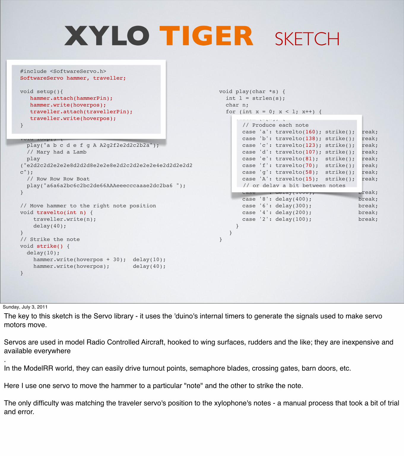
XYLO TIGER SKETCH
#include <SoftwareServo.h>SoftwareServo hammer, traveller;
void setup(){ hammer.attach(hammerPin); hammer.write(hoverpos); traveller.attach(travellerPin); traveller.write(hoverpos); }
void loop() { play("a b c d e f g A A2g2f2e2d2c2b2a"); // Mary had a Lamb play("e2d2c2d2e2e2e8d2d2d8e2e2e8e2d2c2d2e2e2e4e2d2d2e2d2c"); // Row Row Row Boat play("a6a6a2bc6c2bc2de66AAAeeecccaaae2dc2ba6 "); }
// Move hammer to the right note positionvoid travelto(int n) { traveller.write(n); delay(40); }// Strike the notevoid strike() { delay(10); hammer.write(hoverpos + 30); delay(10); hammer.write(hoverpos); delay(40); }
void play(char *s) { int l = strlen(s); char n; for (int x = 0; x < l; x++) { switch (s[x]) { // Produce each note case 'a': travelto(160); strike(); break; case 'b': travelto(138); strike(); break; case 'c': travelto(123); strike(); break; case 'd': travelto(107); strike(); break; case 'e': travelto(81); strike(); break; case 'f': travelto(70); strike(); break; case 'g': travelto(58); strike(); break; case 'A': travelto(15); strike(); break;
// or delay a bit between notes case ' ': delay(1000); break; case '8': delay(400); break; case '6': delay(300); break; case '4': delay(200); break; case '2': delay(100); break; } }}
Sunday, July 3, 2011
The key to this sketch is the Servo library - it uses the 'duino's internal timers to generate the signals used to make servo motors move.
Servos are used in model Radio Controlled Aircraft, hooked to wing surfaces, rudders and the like; they are inexpensive and available everywhere. In the ModelRR world, they can easily drive turnout points, semaphore blades, crossing gates, barn doors, etc.
Here I use one servo to move the hammer to a particular "note" and the other to strike the note.
The only difficulty was matching the traveler servo's position to the xylophone's notes - a manual process that took a bit of trial and error.

LOCONETFAST CLOCKA
SimpleProject
LED display
Shift Registers
&
(optional)
Loconet Interface
Sunday, July 3, 2011
One of the bright points an open source project is when someone reads your postings, gets excited, and follows up with ideas of their own.
One day, Michael sent me email asking about using an Arduino to drive a bunch of cheap fast clocks (Pass around demo)He was looking to have displays around his layout fascia, and wasn't looking forward to buying a dozen commercial clocks
Several email brainstorms later, a simple design came together that could cascade several displays from a single Arduino.

FAST CLOCK SKETCH
void setup() { pinMode(dataPin, OUTPUT); // Configure Pins pinMode(latchPin, OUTPUT); pinMode(clockPin, OUTPUT); pinMode(enable, OUTPUT); pinMode(clr, OUTPUT); digitalWrite(enable, 0); // reset display digitalWrite(clr, 0); delay(10); digitalWrite(clr, 1);}
// Convert time to segment valuesvoid display7Seg(int numberToDisplay) { while (numberToDisplay >= 1000){ thousands++; numberToDisplay -= 1000;} while (numberToDisplay >= 100){ hundreds++; numberToDisplay -= 100;} while (numberToDisplay >= 10){ tens++; numberToDisplay -= 10;} units = numberToDisplay;
sseg_digitValues[3] = sseg_digitLedMap[units]; sseg_digitValues[2] = sseg_digitLedMap[tens]; sseg_digitValues[1] = sseg_digitLedMap[hundreds]; sseg_digitValues[0] = sseg_digitLedMap[thousands];}
void writeOutput(byte value1, byte value2){
digitalWrite(latchPin, LOW); shiftOut(dataPin, clockPin, MSBFIRST, (byte)~value2); shiftOut(dataPin, clockPin, MSBFIRST, (byte)value1); digitalWrite(latchPin, HIGH);}
void loop() { switch (idx) { // 1 digit at a time... case 0: writeOutput(0x01, sseg_digitValues[0]); break; case 1: writeOutput(0x02, sseg_digitValues[1]; break; ... } lc++; if (lc % 12 == 0) idx = (idx + 1) % 4; if (lc == 20000)) { // “fake” clock ticks lc = 0; m++; if (m == 60) { m = 0; h++; if (h == 13) { h = 1;} } display7Seg(time2int(h,m)); }}
Sunday, July 3, 2011
This sketch mocks up the timekeeping portion and focuses on displaying the “time”on the 7-segment display.
Each digit is turned on for a dozen cycles, then we move on to the next. The eye's persistence makes it look like all the digits are on all the time...

BASIC CONCEPTS
• Embedded processors
• Sensors and devices
• Schematics, parts and boards
Sunday, July 3, 2011
Now that we've seen a couple of demos, lets dig a bit deeper and see what goes into making them.

EMBEDDED PROCESSORSEasily programmable (BASIC, simple C, USB port, IDE - FREE)
Some are made for professional electrical engineers, others for experimenters, robotics and artists
More powerful than a TRS-80 (remember them?)Cheaper than a new locomotive
Memory, input and output pins, clocks, timers and other gizmos built in
“Anything you used to do with a soldering iron and a bucket of electronics parts, you can do with an embedded processor”
Sunday, July 3, 2011
All these projects are based on microcontrollers.
A microcontroller is a device that combines a microprocessor (CPU), memory, timers, communication and I/O pins into one package. The differentiation between microcontrollers has to do with how much of, or how many of these things it has. Cheap 8-pin devices may provide 4 or 5 I/O pins, a small amount of program space and a couple of hundred bytes of memory for a dollar, the one used in the Arduino costs about $3, and at the high end, ARM chips go for $10-$25, and can be found in smartphones and iPads...
Iʼve found that all the things I built in the ʻ80s and ʻ90s with hundreds of wire-wrapped parts can be done today with a microcontroller and a couple of simple parts

EMBEDDED PROCESSORSMany types and sizes, relatively inexpensive
Atmel 8-bit AVR Arduino - $30
Atmel 8-bit AVR Arduino Mega - $60
32-bit ARM BeagleBoard - $150
Sunday, July 3, 2011
The Arduino Uno is based on Atmel's lower end AVR 8-bit processor. CLICK (Arduino pix)It has 14 digital pins and 6 analog ones, onboard timers, a serial port, A/D and D/A, hardware Pulse generation, a power supply, some LEDs and a USB interface. What makes this device shine, however, is the development environment that comes with it for free, along with a huge number of "helper libraries" and example sketches It is almost never necessary to write something from scratch; someone somewhere has probably already done something similar, and blogged about it. Google, the Arduino Playground and YouTube are your friends! CLICK (Mega)The next step up is the "mega" - it uses a high end AVR processor with more memory (128Kb instead of 16 or 32), 54 I/O pins, 4 serial ports, more timers and a whole bunch of other fiddly bits - and the same development environment as the Arduino.CLICK (ARM)If these aren't enough, you can step up to ARM based systems. They are significantly more powerful (with graphics & VGA drivers, sound and camera inputs, USB, 128MB memory (instead of Kb) - they can run Linux directly, with Java if you wish, but are a whole 'nuther topic...CLICK (cost) Whichever one you choose, the cost is small compared to what it lets you do!
SENSORS & DEVICES
Inputs
Outputs
sparkfun Motion Sensor
sparkfun Motion Sensor
sparkfun Motion Sensor
LEDs
Switc
hes
Sunday, July 3, 2011
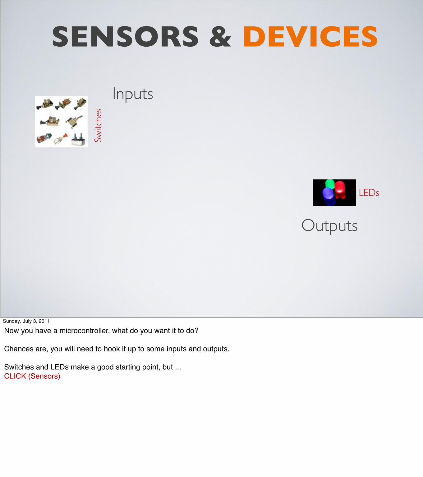
Now you have a microcontroller, what do you want it to do?
Chances are, you will need to hook it up to some inputs and outputs.
Switches and LEDs make a good starting point, but ...CLICK (Sensors)
Inputs
sparkf
un fle
x sen
sor sparkfun RFID
sparkfun
Motion Sensorsparkfun Distance Sensor
sparkfun Voice Recognition
sparkfun Humidity & Temperature
Outputs
sparkfun LCD displays
sparkfun Motion Sensor
sparkfun Motion Sensor
sparkfun Motion Sensor
sparkfun VGA driver
sparkfun Ethernet sparkfun MIDI
sparkfun CAN Bus
Polou 8A H-Bridge
sparkfun Speech Generation
LEDs
Switc
hes
SENSORS & DEVICES
Sunday, July 3, 2011
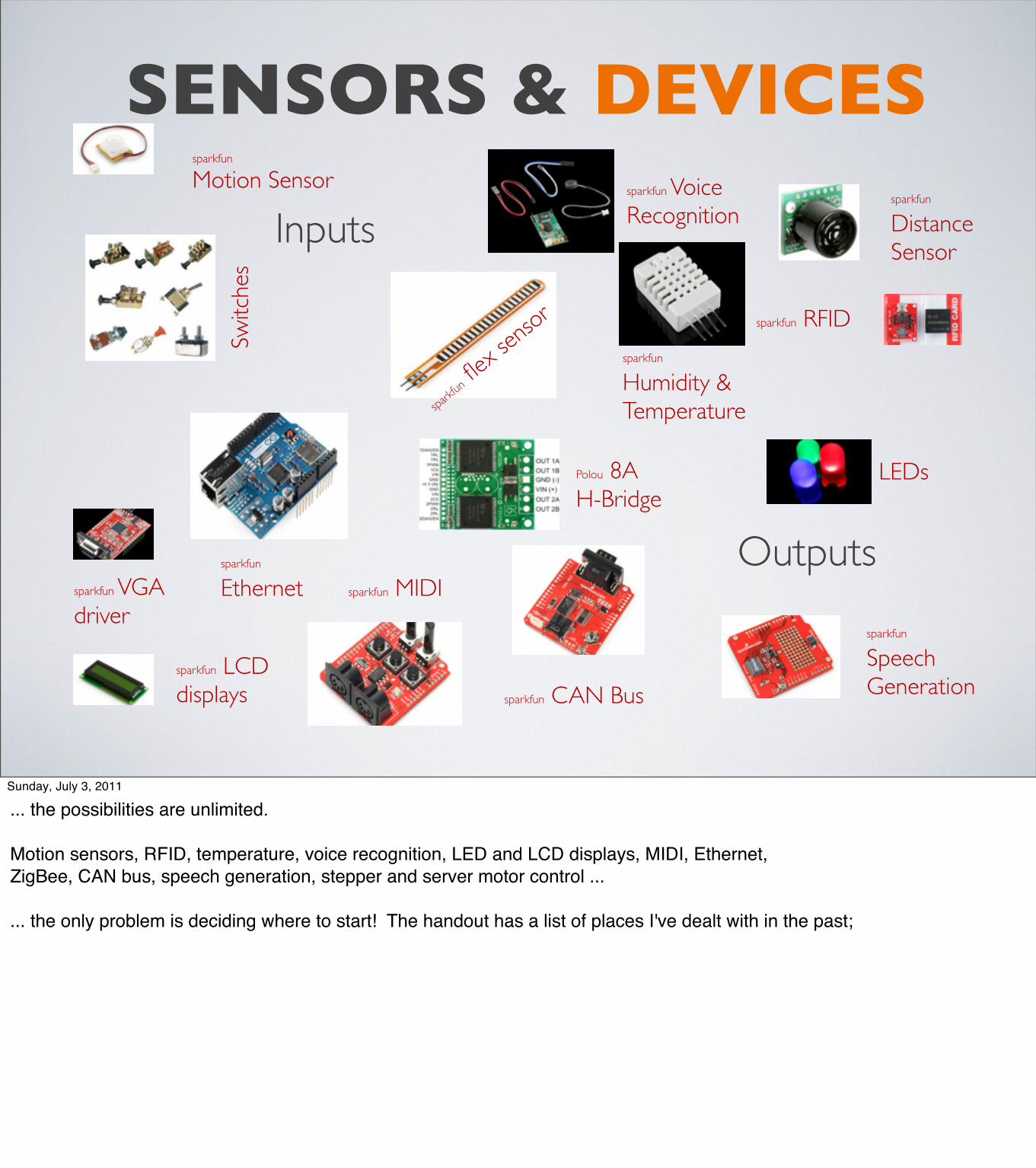
... the possibilities are unlimited.
Motion sensors, RFID, temperature, voice recognition, LED and LCD displays, MIDI, Ethernet, ZigBee, CAN bus, speech generation, stepper and server motor control ...
... the only problem is deciding where to start! The handout has a list of places I've dealt with in the past;

PROTOTYPING
SCHEMATICS PARTS
&BOARDS
Sunday, July 3, 2011
Pulling all these thoughts together...
DIY STEPS
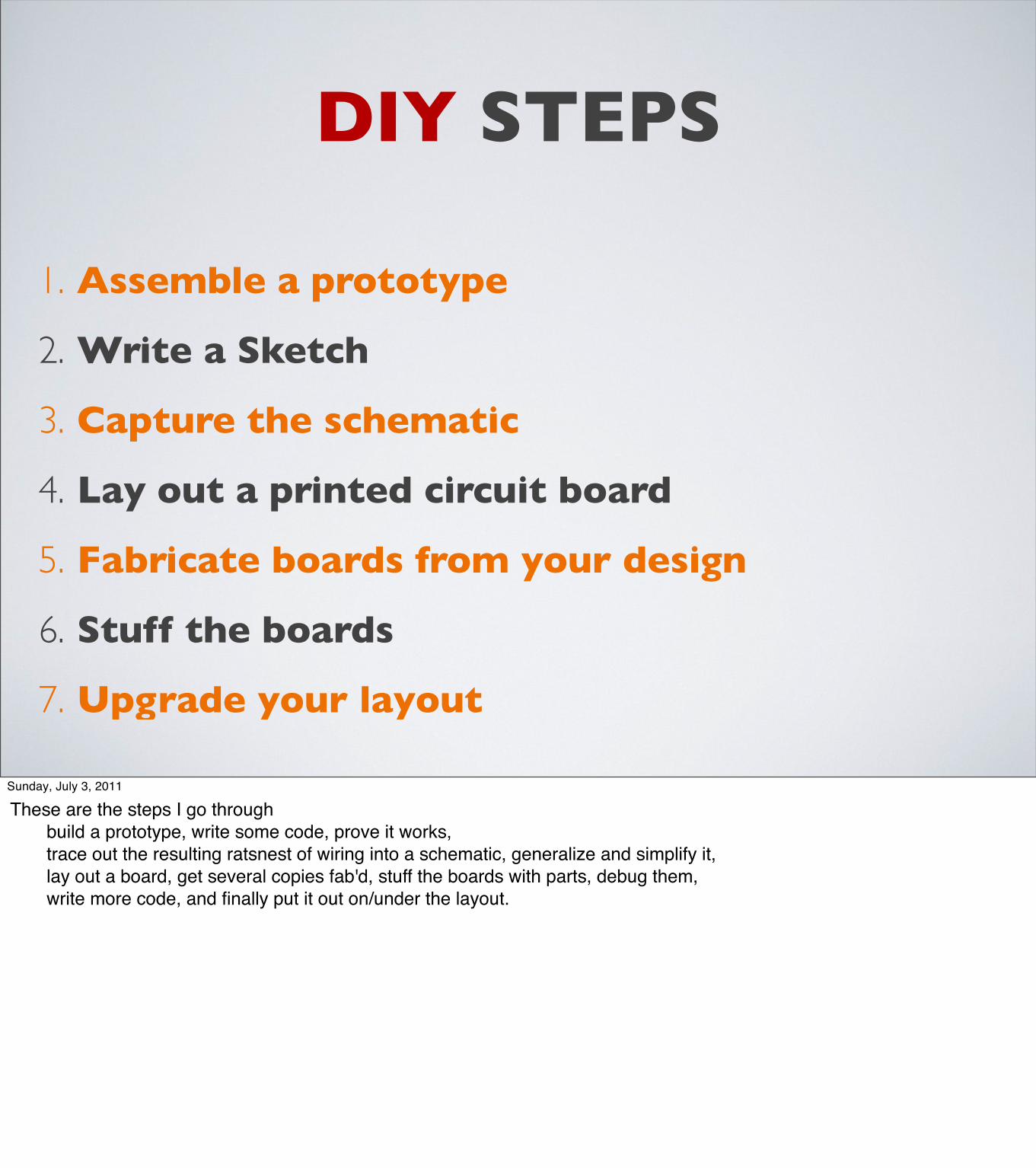
1. Assemble a prototype
2. Write a Sketch
3. Capture the schematic
4. Lay out a printed circuit board
5. Fabricate boards from your design
6. Stuff the boards
7. Upgrade your layout
Sunday, July 3, 2011
These are the steps I go through ! build a prototype, write some code, prove it works, ! trace out the resulting ratsnest of wiring into a schematic, generalize and simplify it, ! lay out a board, get several copies fab'd, stuff the boards with parts, debug them, ! write more code, and finally put it out on/under the layout.

Make a prototype of your idea using breadboards,
jumpers and whatever else you need to play test and get it
working.
This “Loconet Buttons” prototype adds “convenience” buttons to ChuckC’s Loconet layout to do things that otherwise would take some fiddling with a throttle.
EMERGENCY STOP
Track PowerOn/Off
ClearSlots
FeedbackLEDs
Arduino clone Loconet
Sunday, July 3, 2011
Here's an example to show what I mean by prototyping...Over lunch one Friday, Chuck mentioned how frustrating it could get hosting guests on his Digitrax layout - whenever a loco took off or something got bolluxd up, he had to quickly grab a throttle and fix thingsCLICK (details...) His question: Could a 'duino connect a couple of big red buttons to the Loconet and generate emergency STOP and track power commands? And, for extra credit, how about a "clear all slots" button for the end - of - day orderly shutdown?
"Of course" - I already had a Bare Bones Arduino clone and a bunch of Loconet Breadboard adapters, so wiring up 4 buttons and some LEDs didn't take more than a couple of minutes.

LOCONET BUTTONS SKETCH
void loop() { // Check for any received LocoNet packets while (LnPacket = LocoNet.receive() ) { // handles clearing slots if needed... processIncomingLoconetCommand( LnPacket ); } // Check for any buttons pushed... GPonButton = digitalRead(PowerOnPort); GPoffButton = digitalRead(PowerOffPort); EStopButton = digitalRead(EStopPort); ClearButton = digitalRead(SlotClearPort); if (lastGPon == -1) { // need to initialize things the first time lastGPon = GPonButton; lastGPoff = GPoffButton; lastEStop = EStopButton; lastClear = ClearButton; } else { // See if anything has changed // TODO: We're not debouncing the switches if (GPonButton != lastGPon) { lastGPon = GPonButton; if (GPonButton) { sendOPC_GP(ON); } ClearIt = 0; } if (GPoffButton != lastGPoff) { lastGPoff = GPoffButton;
if (GPoffButton) { sendOPC_GP(OFF); } ClearIt = 0; } if (EStopButton != lastEStop) { lastEStop = EStopButton; if (EStopButton) { sendOPC_IDLE(); } ClearIt = 0; } if (ClearButton != lastClear) { lastClear = ClearButton; if (ClearButton) { ClearIt = 1; // query all the slots, // let the handler clear things for (int slot=0; slot<120; slot++) { sendOPC_RQ_SL_DATA(slot); } ClearIt = 0; } } }}
Sunday, July 3, 2011
The code was almost as easy - track the buttons, and, when pressed, use Alexʼs Embedded Loconet library to emit the required packets.
This might be better done as a state machine to handle debouncing, failures and the other obvious corner casesbut for a proof of concept, what is here is sufficient.

CAPTURE YOUR CIRCUIT DESIGN
GOODSCHEMATIC AND PCB SOFTWARE
CAN BE HAD FOR FREE EAGLE CAD: http://cadsoftusa.com (PC, MAC, LINUX)
EXPRESSPCB: http://expressPCB.com (PC ONLY, VENDOR LOCK-IN)
Many places to get boards made for $20 or less,depending on size, quantity and time.
http://www.seeedstudio.comhttp://www.batchpcb.com
http://www.expressPCB.com
Sunday, July 3, 2011
Once you have gotten a prototype working to your satisfaction, you need to decide if you want to stick it in a box and use it as-is, or if you want to clean things up and make circuit boards.
There are several good, free programs you can use to make your own PC Boards; I've used both ExpressPCB and Eagle.
ExpressPCB is easy; ordering boards is as simple as clicking on the "order boards" menu. But, it is PC/Windows only, you can only order boards from their fab factory, and their prices, while reasonable, are higher than others.
Eagle, on the other hand, is a professional package that allows hobbyists like us to use it for free. It is a bit harder to learn, but offers considerably more power and flexibility. Best of all, it is easy to produce files that can be used by any PC fab company in the world - including the ones in China that can produce boards at a fraction of ExpressPCB's.
Instead of "3 boards for $50", there are places in Shenzhen that will make 10 for $10... Of course, the free shipping from China may take a month...

A complete example
This “IO Shield” uses the I2C bus to add sets of 8 digital I/O lines to an Arduino,for signals, buttons and other devices.
I2C bus
Sunday, July 3, 2011
Here's a project that has gone all the way through the development cycle; I call it an IOShield.
I come from a Chubb/CMRI background where there are dozens and dozens of I/O points, and the ability to add more by the dozens on an as-needed basis. Since the Arduino comes as-is with only a few IO pins, I really felt the need to do something.
Turns out that there is a family of inexpensive chips called IO EXPANDERs that are made just for this purpose - each of their 8- or 16 pins can be used for either input or output, the chip is reasonably priced, protected against environmental mishap, and it only uses up 2 of the Arduino's IO pins.
I also fixed one of my pet peeves - the lack of feedback LEDs for each I/O point, so I didn't have to climb back and forth between the computer monitor on top of the layout and my wiring project under the layout just to see if things were connected correctly.
After all, you can't go wrong with more blinking lights!

I2C IO SHIELD SKETCHvoid I2Cextender::init(int address, int chip, int config) { _address = address; _chip = chip; _config = config; switch (_chip) { case I2Cextender::PCA9555: _size = B16; input16(base9555 + _address, _config); break; case I2Cextender::PCF8574A: _size = B8; input8(base8574A + _address, _config); break; case I2Cextender::PCF8574: _size = B8; input8(base8574 + _address, _config); break; default: _size=0; } }
int I2Cextender::read8(int i2caddr) { int _data = -1; Wire.requestFrom(i2caddr, 1); if(Wire.available()) { _data = Wire.receive(); } return _data;}
void I2Cextender::write8(int i2caddr, int data){ Wire.beginTransmission(i2caddr); Wire.send(0xff & data); Wire.endTransmission(); }
...
int I2Cextender::get() { switch (_chip) { case I2Cextender::PCA9555: return read16(base9555 + _address); case I2Cextender::MCP23016: return read16(base23016 + _address); case I2Cextender::PCF8574A: return read8(base8574A + _address); case I2Cextender::PCF8574: return read8(base8574 + _address); default: return -1; } }
void I2Cextender::put(int data) { switch (_chip) { case I2Cextender::PCA9555: write16(base9555 + _address, data); break; case I2Cextender::MCP23016: write16(base23016 + _address, data);break; case I2Cextender::PCF8574A: write8(base8574A + _address, data | _config);break; case I2Cextender::PCF8574: write8(base8574 + _address, data | _config);break; default: break; } }
void setup(){ Wire.begin(); I2CExtender m = I2Cextender(); m.init(0, I2Cextender::PCF8574A, B00001111); // 4 out, 4 in}
Sunday, July 3, 2011
This code is a reusable library; it exposes some C++ syntax, but otherwise is pretty simple:
init, read, write, get and put routines,
with an example of their use.

I2C IO SHIELD SCHEMATIC
First P
ass
Sunday, July 3, 2011
The first version of the IOShield schematic was of a single expander, 8 feedback LEDs and an 8-pin cable for connecting to the various detectors and turnouts.
It was exactly what I had done on a breadboard, and gave me a small PCB with 8 IO connections.

I2C IO SHIELD SCHEMATIC
x 4 ...
Sunday, July 3, 2011
I soon realized how hard it was to mount and use a stack of these cards, especially with all those cables pulling on them.
I redesigned things to put 4 IOexpanders on a single board, made a few changes, and came up with this complicated looking result. CLICK (4X) Note, though, that it really isn't that complicated - it is just 4 of the previous slide stuck together.(Pass around IOShield)

I2C IO SHIELD PCB DESIGN
Sunday, July 3, 2011
The board layout was done to fit within the size limits imposed by the free version of Eagle - about 4"x4".
RJ45 connectors around the edges, with tower LED stacks for feedback, all in an Arduino Shield form factor based on the free Arduino parts library from SparkFun.
Eagle's "AutoRoute" feature made the task easy, just lay out the components where I wanted them and the program figured out how to route all the traces!

I2C IO EXPANDER PCB FAB& STUFF
Sunday, July 3, 2011
Once the board design was done, I sent it off to SeeedStudio to get it fabricated.
Several weeks later, I got a stack of boards in the mail, assembled a couple, and eventually ended up with this.
… Sortof.
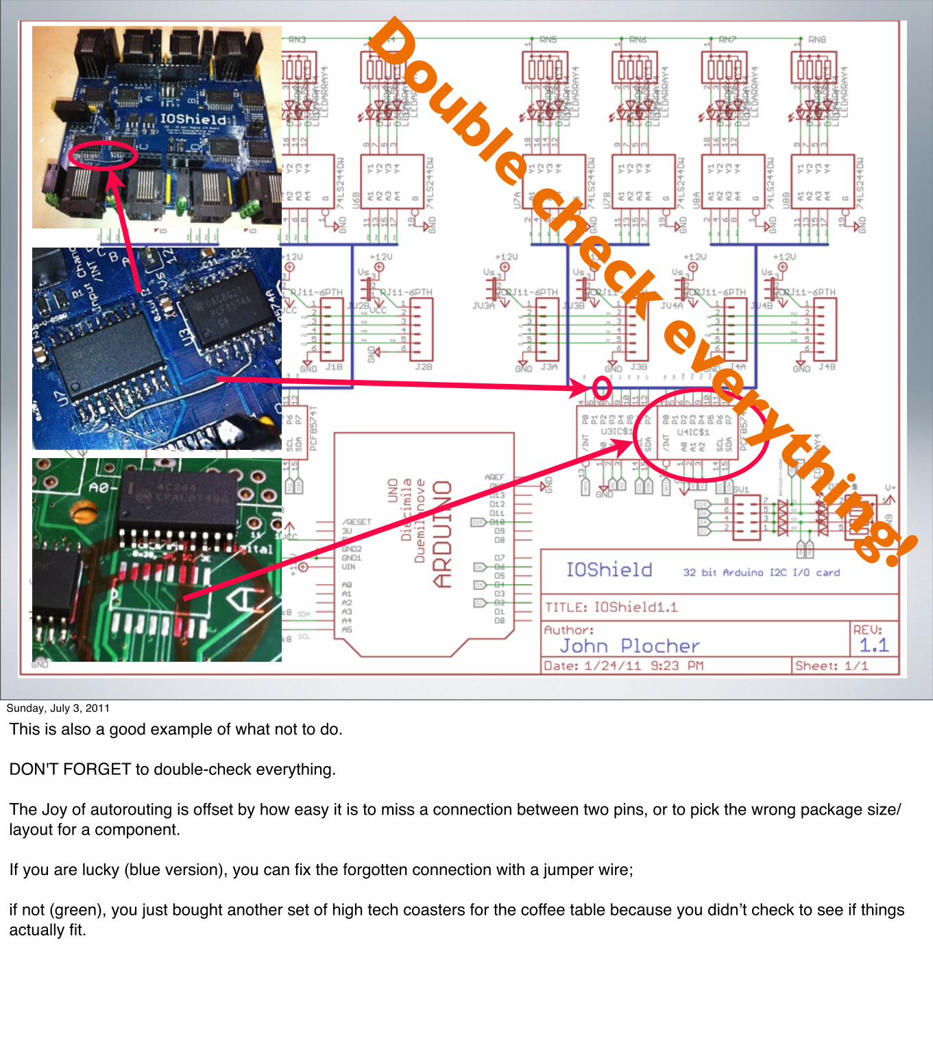
Double check everything!
Sunday, July 3, 2011
This is also a good example of what not to do.
DON'T FORGET to double-check everything.
The Joy of autorouting is offset by how easy it is to miss a connection between two pins, or to pick the wrong package size/layout for a component.
If you are lucky (blue version), you can fix the forgotten connection with a jumper wire;
if not (green), you just bought another set of high tech coasters for the coffee table because you didnʼt check to see if things actually fit.
Sunday, July 3, 2011
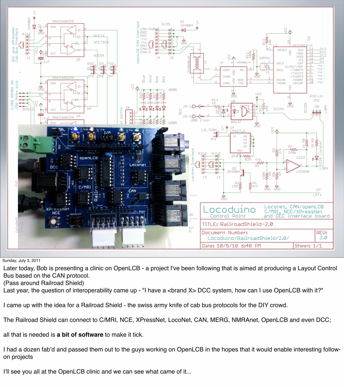
Later today, Bob is presenting a clinic on OpenLCB - a project I've been following that is aimed at producing a Layout Control Bus based on the CAN protocol. (Pass around Railroad Shield) Last year, the question of interoperability came up - "I have a <brand X> DCC system, how can I use OpenLCB with it?"
I came up with the idea for a Railroad Shield - the swiss army knife of cab bus protocols for the DIY crowd.
The Railroad Shield can connect to C/MRI, NCE, XPressNet, LocoNet, CAN, MERG, NMRAnet, OpenLCB and even DCC;
all that is needed is a bit of software to make it tick.
I had a dozen fabʼd and passed them out to the guys working on OpenLCB in the hopes that it would enable interesting follow-on projects
Iʼll see you all at the OpenLCB clinic and we can see what came of it...

EXPERIMENTS: CTC & CONTROL POINT
Sunday, July 3, 2011
Several years ago, BobJ and I had a discussion about the "architecture" of JMRI.

A FATEFUL DISCUSSION + A SIMPLE REQUEST = AN OBSESSION
• A discussion with BobJ about thelevel of detail exposed by JMRI
• A request from a neighbor to help him understand ATCS(a radio codeline used bymany US railroads today)
• Is there a better way?
Sunday, July 3, 2011
I mentioned that, as a software architect, I was somewhat uncomfortable with how much "layout implementation detail" leaked up through JMRI into the applications people were building - things tended to use "CMRI Node 3 pin 22" or "Loconet Turnout number 17" instead of "Control Point Michael track circuit 2S Approach" In the end, Bob said, "code wins", and suggested I go off and try something.
Soon after, a neighbor of mine - who works for Caltrain doing signal maintenance stuff - asked me for help with ATCS – the Advanced Train Control System. Caltrain was deploying a radio version of the venerable cTc codeline, and he had heard that ATCSmon (a program used by the railfan community to monitor ATCS radio traffic) might be of interest. Several months (and a new ham radio license) later, I had put up an ATCSmon server site (shown in the picture) for Caltrain in the South Bay, and was learning quite a bit about "modern" railroad control systems.
We seem to care a lot about prototypical exactness in rolling stock detail, structures and track plans, in fidelity to timetables, rules and operations on top of the layout...why then do the undersides of our layouts look like a nightmare in a yarn factory?
Could we learn anything from the prototype in how we wire and control our layouts?

WHY DON’T WE WIRE OUR LAYOUTS MORE LIKE THE PROTOTYPE?• Vital logic distributed ‘round
the layout at each Control Point
• Code lines and packets, not a central PC with lots of wires
• An excuse to play with Arduinos!
Sunday, July 3, 2011
What did I learn from ATCS?•! The railroads are really made up of interlockings connected by track. •! Interlockings are places where the movement of trains is controlled or changed with turnouts and signals. •! In general, trains don't stop "in" interlockings, they stop "before" them. •! The Control Points are really clusters of Vital Logic - relays, microprocessors, electronics and mechanical apparatus that allow the dispatcher to safely control the plant•! Everything the dispatcher needs (switch position, track circuit state, signals) is exposed as bits in Indication and Control Packets,• The things that arenʼt needed (whether the signal displays restricted or approach or clear instead of just stop and not-stop
this was a perfect excuse to do something non-trivial with a bunch of Arduinos on my layout.
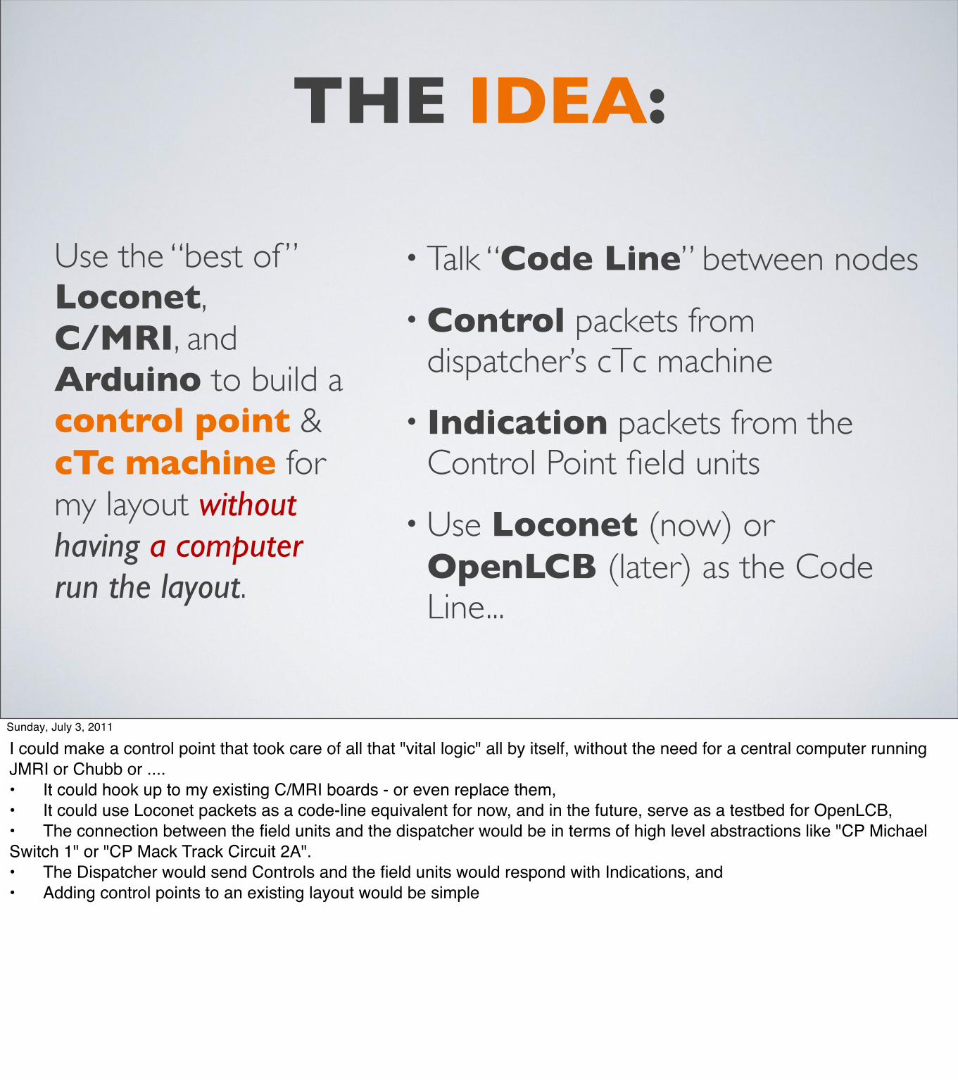
THE IDEA:
Use the “best of ” Loconet, C/MRI, and Arduino to build a control point & cTc machine for my layout without having a computer run the layout.
• Talk “Code Line” between nodes
• Control packets from dispatcher’s cTc machine
• Indication packets from the Control Point field units
• Use Loconet (now) or OpenLCB (later) as the Code Line...
Sunday, July 3, 2011
I could make a control point that took care of all that "vital logic" all by itself, without the need for a central computer running JMRI or Chubb or ....•! It could hook up to my existing C/MRI boards - or even replace them, •! It could use Loconet packets as a code-line equivalent for now, and in the future, serve as a testbed for OpenLCB, •! The connection between the field units and the dispatcher would be in terms of high level abstractions like "CP Michael Switch 1" or "CP Mack Track Circuit 2A". •! The Dispatcher would send Controls and the field units would respond with Indications, and•! Adding control points to an existing layout would be simple
THERESULT
A “LAYOUT” WITHOUT ALL THOSE PESKY
TRACKS...
Sunday, July 3, 2011
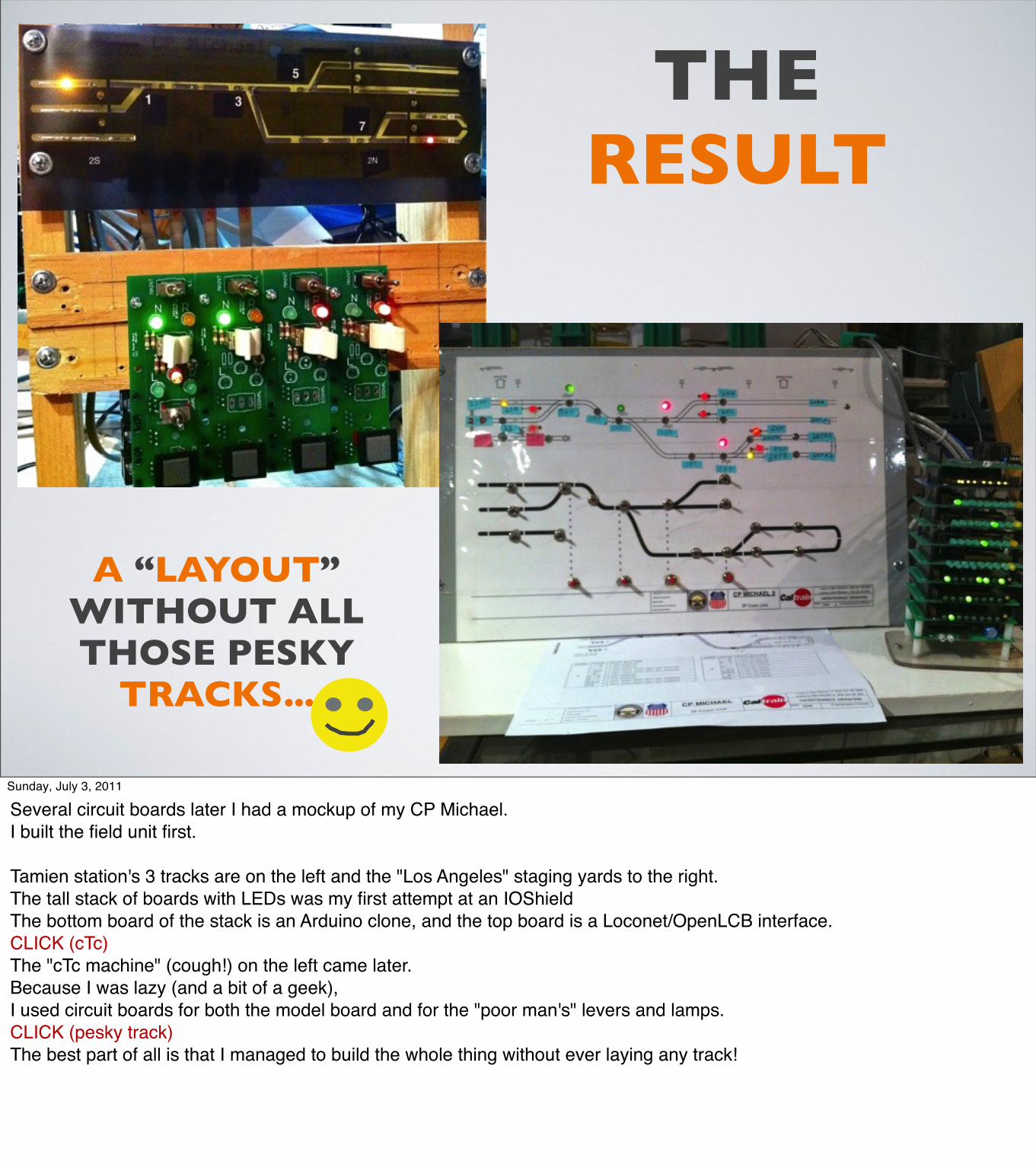
Several circuit boards later I had a mockup of my CP Michael.I built the field unit first.
Tamien station's 3 tracks are on the left and the "Los Angeles" staging yards to the right. The tall stack of boards with LEDs was my first attempt at an IOShieldThe bottom board of the stack is an Arduino clone, and the top board is a Loconet/OpenLCB interface.CLICK (cTc)The "cTc machine" (cough!) on the left came later. Because I was lazy (and a bit of a geek), I used circuit boards for both the model board and for the "poor man's" levers and lamps. CLICK (pesky track) The best part of all is that I managed to build the whole thing without ever laying any track!

CP MICHAEL
• 16 Track Circuits
• 4 Switches
• 6 Signals
and a little imagination
(it is a work in progress ;-)
Sunday, July 3, 2011
The cTc station uses a stock Arduino, a couple of the new IOShields and a Railroad Shield.
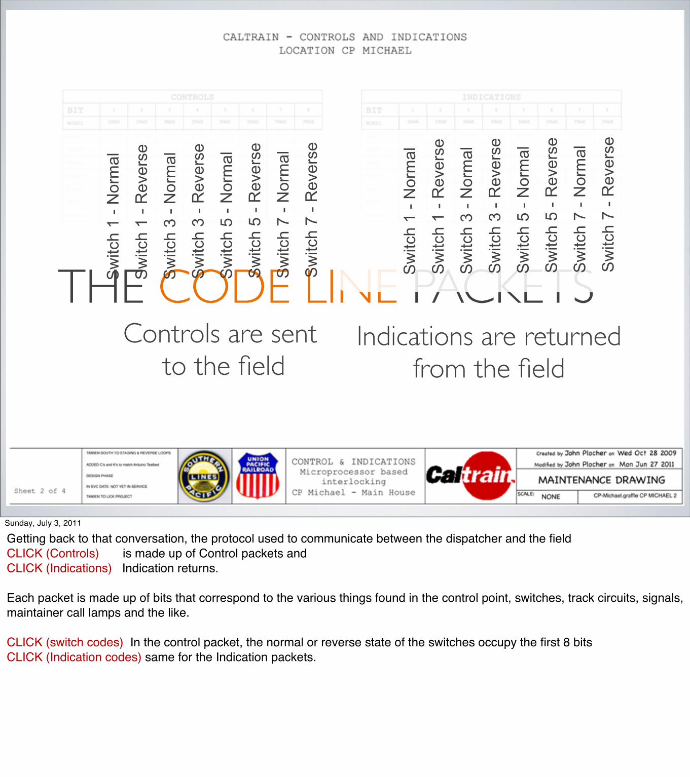
THE CODE LINE PACKETSSw
itch
1 - N
orm
al
Sw
itch
1 - R
ever
se
Sw
itch
3 - N
orm
al
Sw
itch
3 - R
ever
se
Sw
itch
5 - N
orm
al
Sw
itch
5 - R
ever
se
Sw
itch
7 - N
orm
al
Sw
itch
7 - R
ever
seControls are sent
to the fieldS
witc
h 1
- Nor
mal
Sw
itch
1 - R
ever
se
Sw
itch
3 - N
orm
al
Sw
itch
3 - R
ever
se
Sw
itch
5 - N
orm
al
Sw
itch
5 - R
ever
se
Sw
itch
7 - N
orm
al
Sw
itch
7 - R
ever
se
Indications are returnedfrom the field
Sunday, July 3, 2011
Getting back to that conversation, the protocol used to communicate between the dispatcher and the field CLICK (Controls) is made up of Control packets and CLICK (Indications) Indication returns.
Each packet is made up of bits that correspond to the various things found in the control point, switches, track circuits, signals, maintainer call lamps and the like.
CLICK (switch codes) In the control packet, the normal or reverse state of the switches occupy the first 8 bits CLICK (Indication codes) same for the Indication packets.
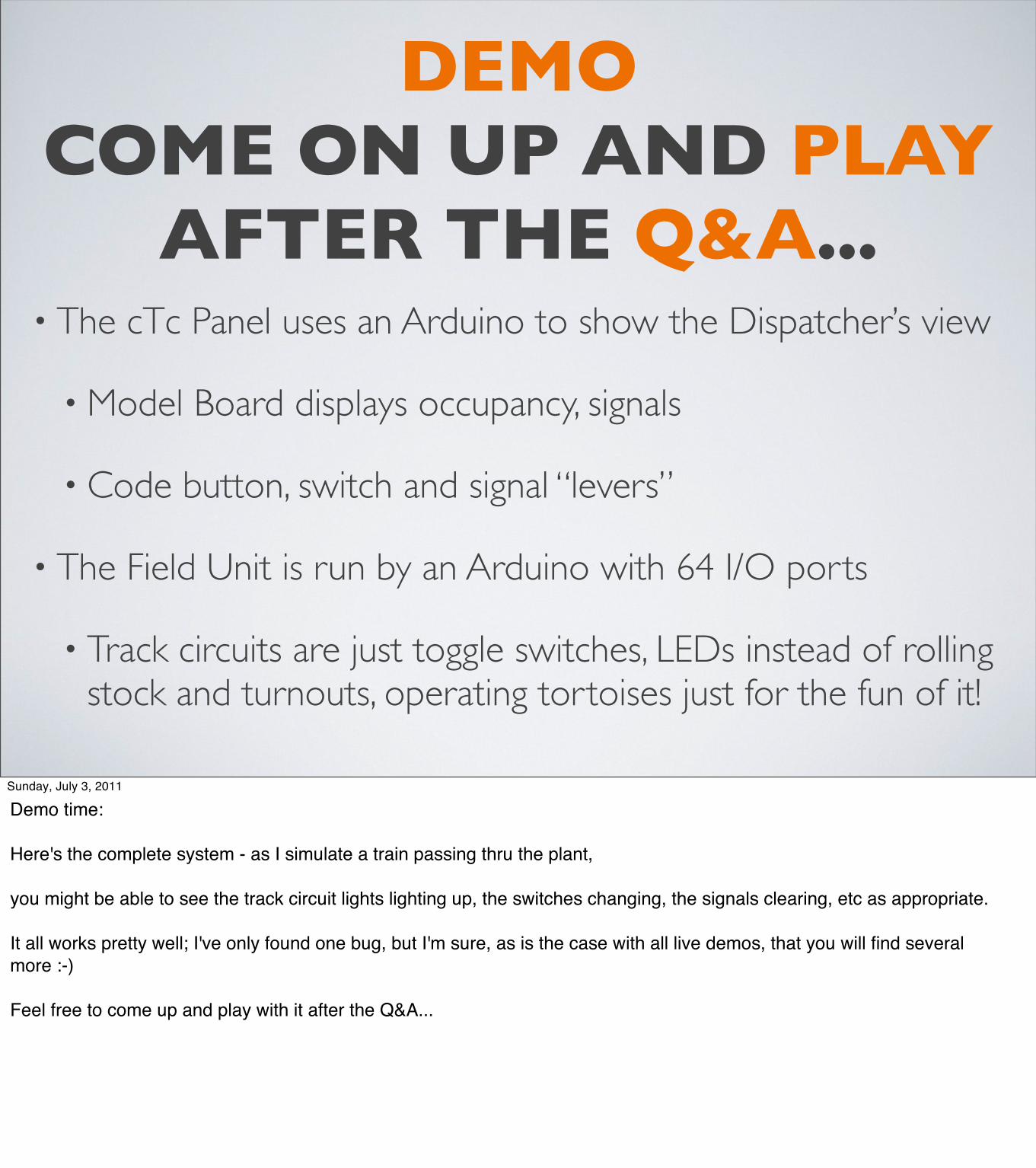
DEMOCOME ON UP AND PLAY
AFTER THE Q&A...• The cTc Panel uses an Arduino to show the Dispatcher’s view
• Model Board displays occupancy, signals
• Code button, switch and signal “levers”
• The Field Unit is run by an Arduino with 64 I/O ports
• Track circuits are just toggle switches, LEDs instead of rolling stock and turnouts, operating tortoises just for the fun of it!
Sunday, July 3, 2011
Demo time:
Here's the complete system - as I simulate a train passing thru the plant,
you might be able to see the track circuit lights lighting up, the switches changing, the signals clearing, etc as appropriate.
It all works pretty well; I've only found one bug, but I'm sure, as is the case with all live demos, that you will find several more :-)
Feel free to come up and play with it after the Q&A...
WITH ARDUINOS,IT IS EASIER THAN EVER
TO TURN YOUR IDEAS INTO REALITY
Sunday, July 3, 2011
If you take anything home with you from this clinic
(other than the handout )
I hope it is a new enthusiasm for playing with these high tech toys.
Arduinos are inexpensive, easy to use and unlock an unlimited set of possibilities!
Thank you all for coming to my first convention clinic, I hope you enjoyed it – I certainly did!

EXTRA 2011 WEST
Q&A
John Plocher
Silicon Valley Lines Model Railroad Club
EXTRA 2011 WEST
Sunday, July 3, 2011
Related Documents