1 SLVA968A – January 2019 – Revised February 2019 Submit Documentation Feedback Copyright © 2019, Texas Instruments Incorporated External or Internal FETs for Motor Drive in Automotive Applications Application Report SLVA968A – January 2019 – Revised February 2019 External or internal FETs for motor drive in automotive applications Automotive Systems ABSTRACT Modern automobiles use electric motors to drive an increasing number of applications, such as power windows, locks, seats, mirror adjustments, blowers, and trunk lifts. Transistor-based solid-state drive circuits are used to switch the current to the motors used in these applications. Designers can choose motor drive integrated circuits (IC) with either external field-effect transistors (FETs) or internal FETs for the final drive stage. This document discusses some of the tradeoffs in choosing the external-FET or internal-FET approach. Additionally, this application report focuses on key comparisons in terms of board size and thermal performance. Contents 1 Introduction ................................................................................................................... 2 2 Flexibility and Simplicity..................................................................................................... 4 2.1 External-FET Topology Offers Flexibility ........................................................................ 4 2.2 Internal-FET Topology Offers Simplicity ......................................................................... 4 3 Board Area Comparisons ................................................................................................... 4 3.1 Board Area Considerations ........................................................................................ 4 3.2 Board Area for External-FET Topology .......................................................................... 5 3.3 Board Area for Internal-FET Topology ........................................................................... 7 3.4 Summary of Board Area Comparison ........................................................................... 8 4 Thermal Comparisons ..................................................................................................... 10 4.1 Thermal Considerations .......................................................................................... 10 4.2 Thermal Estimates for Gate Driver External-FET Topology ................................................. 12 4.3 Thermal Estimates for Multi-Chip Module Internal-FET Topology .......................................... 13 4.4 Summary of Thermal Comparisons ............................................................................. 13 5 Summary .................................................................................................................... 15 6 References .................................................................................................................. 15 Trademarks All trademarks are the property of their respective owners.

Welcome message from author
This document is posted to help you gain knowledge. Please leave a comment to let me know what you think about it! Share it to your friends and learn new things together.
Transcript

1SLVA968A–January 2019–Revised February 2019Submit Documentation Feedback
Copyright © 2019, Texas Instruments Incorporated
External or Internal FETs for Motor Drive in Automotive Applications
Application ReportSLVA968A–January 2019–Revised February 2019
External or internal FETs for motor drive inautomotive applications
Automotive Systems
ABSTRACTModern automobiles use electric motors to drive an increasing number of applications, such as powerwindows, locks, seats, mirror adjustments, blowers, and trunk lifts. Transistor-based solid-state drivecircuits are used to switch the current to the motors used in these applications. Designers can choosemotor drive integrated circuits (IC) with either external field-effect transistors (FETs) or internal FETs forthe final drive stage. This document discusses some of the tradeoffs in choosing the external-FET orinternal-FET approach. Additionally, this application report focuses on key comparisons in terms of boardsize and thermal performance.
Contents1 Introduction ................................................................................................................... 22 Flexibility and Simplicity..................................................................................................... 4
2.1 External-FET Topology Offers Flexibility ........................................................................ 42.2 Internal-FET Topology Offers Simplicity ......................................................................... 4
3 Board Area Comparisons ................................................................................................... 43.1 Board Area Considerations........................................................................................ 43.2 Board Area for External-FET Topology .......................................................................... 53.3 Board Area for Internal-FET Topology ........................................................................... 73.4 Summary of Board Area Comparison ........................................................................... 8
4 Thermal Comparisons ..................................................................................................... 104.1 Thermal Considerations .......................................................................................... 104.2 Thermal Estimates for Gate Driver External-FET Topology ................................................. 124.3 Thermal Estimates for Multi-Chip Module Internal-FET Topology .......................................... 134.4 Summary of Thermal Comparisons............................................................................. 13
5 Summary .................................................................................................................... 156 References .................................................................................................................. 15
TrademarksAll trademarks are the property of their respective owners.

Introduction www.ti.com
2 SLVA968A–January 2019–Revised February 2019Submit Documentation Feedback
Copyright © 2019, Texas Instruments Incorporated
External or Internal FETs for Motor Drive in Automotive Applications
1 IntroductionIn today's automotive industry, many electric motors are added to cars due to the benefits of automation,enhanced safety, and luxury features. Motors are found in applications such as electric power steering,brakes, engine and transmission, power seats, windows, doors and trunks. Figure 1 shows an overview ofsome of the areas where electric motors are used in a car.
Figure 1. Automotive Electric Motor Application Examples
These electric motors can be brushed DC, brushless DC, or stepper motors. This document focuses onbrushed DC (BDC) motors because they are the most common. But most of the tradeoffs involvinginternal or external design also apply to driving brushless DC motors or stepper motors.
The circuit arrangement for a brushed DC motor driver typically consists of a drive stage made up of twohigh-side switches and two low-side switches, all of which are controlled by logic. In general the two high-side switches and two low-side switches are implemented as n-channel field-effect transistors (FETs). N-channel FETs are more common than p-channel FETs due to the higher effective current density which, inturn, is due to the higher mobility of electrons (n-channel charge carriers) compared to holes (p-channelcharge carriers). This arrangement is typically called a full-bridge motor driver, or sometimes an H-bridgemotor driver, due to the shape typically drawn of the electrical schematic.
The full-bridge motor driver is typically implemented using one of the following three topologies:1. Gate Driver external-FET topology: In this topology, the drive FETs and the FET controller are in
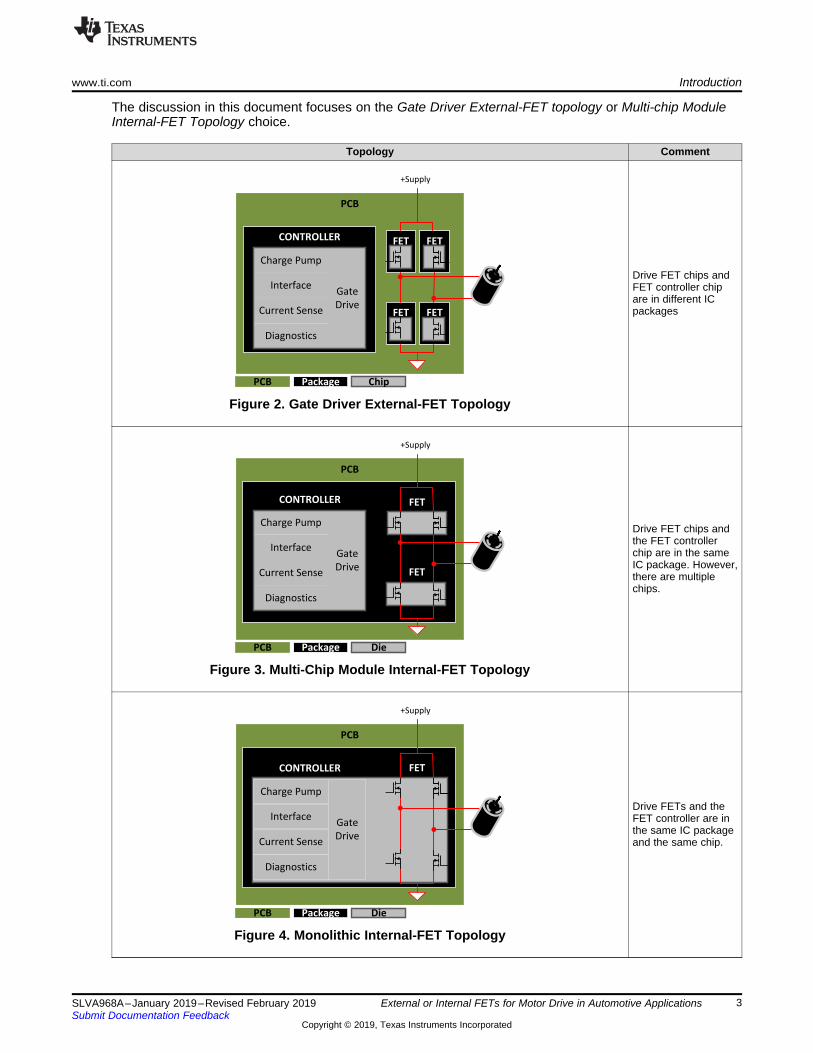
different IC packages. Figure 2 shows an implementation of the motor driver circuit with a controllerchip that includes gate driver, charge pump, control circuits, diagnostics and current sense, along withfour external FETs; that is, the FETs are not in the same IC package as the controller chip. Thisarrangement allows the designer to select the controller and the FETs independently, which givesflexibility to optimize the motor driver design.
2. Multi-chip Module Internal-FET Topology: In this topology, the drive FETs and the FET controllerare in different semiconductor chips, but are encapsulated in the same package in the form of a multi-chip module (MCM) as Figure 3 shows. In some MCM implementations, some (but not all) of the finaldrive-stage FET chips are in the same chip as the controller chip.
3. Monolithic Internal-FET Topology: In this topology, the drive FETs and the FET controller are in thesame IC package. Moreover, all of the drive FETs and the FET controller are in same semiconductorchip; that is, it is a monolithic chip as Figure 4 shows. This topology is typically used for low motorcurrent applications.
PCB
CONTROLLER
+Supply
Gate
Drive
Charge Pump
Interface
Diagnostics
Current Sense
FET
xxxxxxxxx
x
PCB Package Die
PCB
FET
FET
CONTROLLER
+Supply
xxxxxxxxx
x
Gate
Drive
Charge Pump
Interface
Diagnostics
Current Sense
PCB Package Die
PCB
FET
FET
FET
FET
+Supply
CONTROLLER
Gate
Drive
Charge Pump
Interface
Diagnostics
Current Sense
xxxxxxxxx
x
PCB Package Chip
www.ti.com Introduction
3SLVA968A–January 2019–Revised February 2019Submit Documentation Feedback
Copyright © 2019, Texas Instruments Incorporated
External or Internal FETs for Motor Drive in Automotive Applications
The discussion in this document focuses on the Gate Driver External-FET topology or Multi-chip ModuleInternal-FET Topology choice.
Topology Comment
Figure 2. Gate Driver External-FET Topology
Drive FET chips andFET controller chipare in different ICpackages
Figure 3. Multi-Chip Module Internal-FET Topology
Drive FET chips andthe FET controllerchip are in the sameIC package. However,there are multiplechips.
Figure 4. Monolithic Internal-FET Topology
Drive FETs and theFET controller are inthe same IC packageand the same chip.

Flexibility and Simplicity www.ti.com
4 SLVA968A–January 2019–Revised February 2019Submit Documentation Feedback
Copyright © 2019, Texas Instruments Incorporated
External or Internal FETs for Motor Drive in Automotive Applications
2 Flexibility and SimplicityIn general, there is a tradeoff between the design flexibility of using external FETs and the designsimplicity of an internal-FET approach. Which choice is better depends on the requirements of theapplication as well as the priorities of the circuit designer.
2.1 External-FET Topology Offers FlexibilityExternal FETs give a designer the flexibility to use one circuit design for a variety of different applications,simply by allowing designers to choose drive FETs which best suit the requirements of the application.FETs with larger geometry tend to have lower on-resistance, or RDS(on), for a given gate voltage. LowerRDS(on) reduces the losses due to the motor current causing voltage drop across the drive FETs. This leadsto power dissipation in each FET, which is given by the product of the square of the FET current and theFET RDS(on). Note that the maximum current rating of a FET is closely related to RDS(on) of the FET and thethermal properties of the package.
One possible drawback of choosing larger size FET packages is the overall printed-circuit board (PCB)size. Perhaps counter-intuitively, Section 3 shows that external-FET implementations are similar in size tointernal-FET devices with comparable performance. Designers should consider both the current rating andthe thermal specification for the FET package; this tradeoff is discussed more in Section 4.
2.2 Internal-FET Topology Offers SimplicityA motor driver with internal FETs can simplify the design process by providing an all-in-one solution.Texas Instruments offers several motor drivers with internal FETs, with peak drive current capabilitiesranging from 1 Amp to 10 Amps. These devices minimize the design effort needed for getting started witha motor drive application, as the internal transistor characteristics are already selected to match therequirements of the specified motor current.
With the drive FETs in the same IC package as the controller, complete testing of the whole drive circuitduring production assures the device will perform as expected. Having the FETs in the same package asthe drive logic also simplifies monitoring the temperature of the FETs for diagnostic purposes. Additionally,the internal-FET approach simplifies the bill of materials and layout of the circuit board. Especially forapplications with relatively low motor current, motor drivers with internal FETs can be an attractivesolution.
3 Board Area ComparisonsIn many cases the physical size of the PCB is constrained. When board size is limited, internal-FETdrivers may seem to have an inherent advantage due to the reduced number of semiconductor packages.However, the actual size of the external-FET and internal-FET topologies depends on several variables; inthe following sections we compare board area for the Gate Driver External-FET Topology solution inFigure 2 and the Multi-chip Module internal-FET Topology solution in Figure 3.
3.1 Board Area ConsiderationsWhen comparing the board area for various implementations, there are several factors to consider. Theseinclude:• Maximum motor current - this is related to RDS(on)
• Maximum motor voltage• Uni-directional or bidirectional motion - we focus on bidirectional solutions, recognizing that uni-
directional motion solutions will be a subset of the full-bridge implementation• Method of current sensing• Diagnostic and protection features• Number of external components needed• Component spacing rules for manufacturing

www.ti.com Board Area Comparisons
5SLVA968A–January 2019–Revised February 2019Submit Documentation Feedback
Copyright © 2019, Texas Instruments Incorporated
External or Internal FETs for Motor Drive in Automotive Applications
In addition to the FET and the controller chips, several external components are typically required toimplement a complete motor drive solution. These external components may include:• Decoupling capacitors to stabilize the power supply for the motor driver control circuits• Bulk capacitors to stabilize the power supply for the internal drive FETs during motor transients• Resistor to scale the motor current sense signal to a desired voltage range• Resistor and capacitor to filter the motor current sense signal• FET, diodes, and resistors to provide reverse battery voltage protection• Resistors on each signal line to the microcontroller• Transient voltage suppressor for load dump transients
3.2 Board Area for External-FET TopologySince the drive FETs can be selected independent of the controller, there are many options to considerwhen determining the size of the motor driver solution with external FETs. FET packages are available ina variety of sizes and configurations. This document discusses the trends in package size versus RDS(on)for both single-FET implementations and dual-FET implementations of a full-bridge drive circuit.
In addition to the drive FETs forming the full-bridge, the external-FET implementation includes a controllerchip, which typically integrates the necessary gate driver circuits, charge pumps, diagnostic features, andin many cases current sense amplifiers.
For the Gate Driver external-FET topology in Figure 2, one implementation is to use four single externalFETs for the full-bridge. Figure 5 shows a scatter plot of the data for several FETs, with the board area forfour single FETs plotted on the vertical axis, versus the RDS(on) for one high-side and one low-side FETplotted on the horizontal axis. The horizontal scale is logarithmic, to better show the wide range of RDS(on)values available with external FETs. To remove the effect of other factors on these data points, all of thetransistors represented are single n-channel silicon FETs with automotive ratings, and they all have amaximum VDS rating of 60 V.
Figure 5. Full-Bridge Board Area vs High-Side + Low-Side RDS(on), Single External FETs

Board Area Comparisons www.ti.com
6 SLVA968A–January 2019–Revised February 2019Submit Documentation Feedback
Copyright © 2019, Texas Instruments Incorporated
External or Internal FETs for Motor Drive in Automotive Applications
Although a wide variety of options available exist, the general trend is that if only a small board area isavailable, the active RDS(on) will be towards the higher values. Conversely, if a high-current applicationrequires very low RDS(on), the board size will not be as small as lower-current (higher RDS(on)) cases. SingleFETs are also available in packages such as the TO-220, which offer additional flexibility in layout. TheTO-220 can be mounted with the large dimension vertically, so that only the board area used for the threepins is needed. This also provides another dimension for mounting a heat sink, if needed.
Another option to consider when board space is limited, is to use dual-FET devices, which combine twoFETs in a single package. This can reduce the board size needed for a motor driver without restricting theavailable options to only the limited number of motor drivers with internal FETs. Although there are fewerchoices for dual-FET package size, Figure 6 shows the same general trend of increasing board size asthe RDS(on) specification decreases.
Figure 6. Full-Bridge Board Area vs High-Side + Low-Side RDS(on), Dual External FETs

www.ti.com Board Area Comparisons
7SLVA968A–January 2019–Revised February 2019Submit Documentation Feedback
Copyright © 2019, Texas Instruments Incorporated
External or Internal FETs for Motor Drive in Automotive Applications
3.3 Board Area for Internal-FET TopologyFigure 7 illustrates the data for internal-FET topologies. This figure includes both the multi-chip moduleand monolithic topologies and shows that the package size for full-bridge devices must increasesignificantly to provide RDS(on) reduction. This is primarily due to the larger semiconductor chip size neededto provide low RDS(on).
Figure 7. Full-Bridge Board Area vs High-Side + Low-Side RDS(on), Internal-FET Devices
Table 1 summarizes the data used to generate Figure 7. It is noted that Table 1 lists some of theautomotive motor drive solutions with internal drive FETs which are available from Texas Instruments andother semiconductor manufacturers. The selection is limited to devices with voltage ratings of 40 V,consistent with automotive battery supply systems due to the typical load-dump voltage requirement. Thedimensions are for this motor driver component only, not including any necessary ancillary components.The listed RDS(on) values used for this comparison are for a path through the driver, including one high-sideFET and one low-side FET.
Table 1. Package Sizes for Examples of Motor Drivers With Internal FETs
Example Package Dimensions(including pins)
Board Area(mm2) RDS(on) per H+L pair Voltage Rating
1 24-pin Thin Small Outline 7.8 mm × 6.4 mm 49.9 150 mΩ (typical)310 mΩ maximum 40 V absolute maximum
2 16-pin Small Outline 9.9 mm × 6 mm 59.4 100 mΩ (typical)200 mΩ maximum
38 V absolute maximum, 40 Vwith external clamp
3 36-pin Small OutlinePower 10.3 mm x 10.3 mm 106.1 41 mΩ (typical)
80 mΩ maximum38 V absolute maximum, 40 V
with external clamp
4 36-pin 12.8 mm x 10.3 mm 131.8 150 mΩ (typical)295 mΩ maximum 45 V absolute maximum
5 28-pin Small Outline 17.9 mm x 10.3 mm 184.4 95 mΩ (typical)190 mΩ maximum 41 V absolute maximum
6 7-pin Transistor Outline(two required)
10 mm x 15 mm (tworequired) 310 10 mΩ (typical)
28.7 mΩ maximum 40 V absolute maximum
7 30-pin Small Outline 17.2 mm x 19 mm 327 18 mΩ (typical)38 mΩ maximum 41 V absolute maximum
Board Area Comparisons www.ti.com
8 SLVA968A–January 2019–Revised February 2019Submit Documentation Feedback
Copyright © 2019, Texas Instruments Incorporated
External or Internal FETs for Motor Drive in Automotive Applications
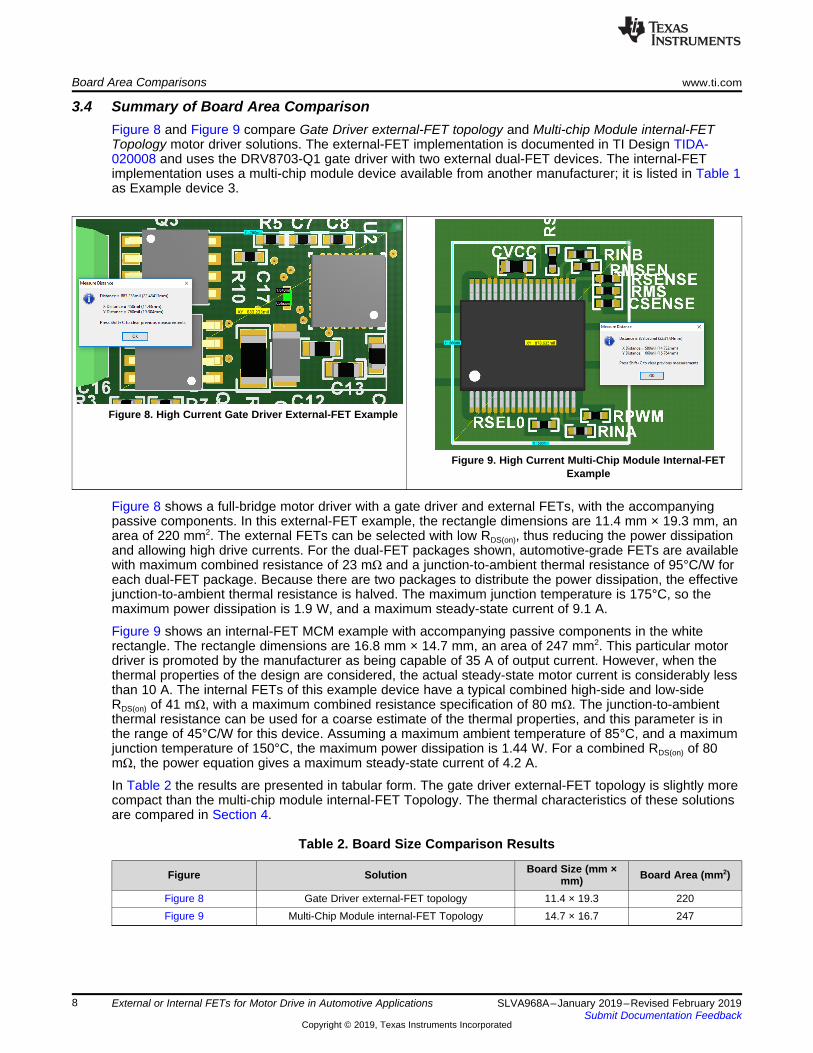
3.4 Summary of Board Area ComparisonFigure 8 and Figure 9 compare Gate Driver external-FET topology and Multi-chip Module internal-FETTopology motor driver solutions. The external-FET implementation is documented in TI Design TIDA-020008 and uses the DRV8703-Q1 gate driver with two external dual-FET devices. The internal-FETimplementation uses a multi-chip module device available from another manufacturer; it is listed in Table 1as Example device 3.
Figure 8. High Current Gate Driver External-FET Example
Figure 9. High Current Multi-Chip Module Internal-FETExample
Figure 8 shows a full-bridge motor driver with a gate driver and external FETs, with the accompanyingpassive components. In this external-FET example, the rectangle dimensions are 11.4 mm × 19.3 mm, anarea of 220 mm2. The external FETs can be selected with low RDS(on), thus reducing the power dissipationand allowing high drive currents. For the dual-FET packages shown, automotive-grade FETs are availablewith maximum combined resistance of 23 mΩ and a junction-to-ambient thermal resistance of 95°C/W foreach dual-FET package. Because there are two packages to distribute the power dissipation, the effectivejunction-to-ambient thermal resistance is halved. The maximum junction temperature is 175°C, so themaximum power dissipation is 1.9 W, and a maximum steady-state current of 9.1 A.
Figure 9 shows an internal-FET MCM example with accompanying passive components in the whiterectangle. The rectangle dimensions are 16.8 mm × 14.7 mm, an area of 247 mm2. This particular motordriver is promoted by the manufacturer as being capable of 35 A of output current. However, when thethermal properties of the design are considered, the actual steady-state motor current is considerably lessthan 10 A. The internal FETs of this example device have a typical combined high-side and low-sideRDS(on) of 41 mΩ, with a maximum combined resistance specification of 80 mΩ. The junction-to-ambientthermal resistance can be used for a coarse estimate of the thermal properties, and this parameter is inthe range of 45°C/W for this device. Assuming a maximum ambient temperature of 85°C, and a maximumjunction temperature of 150°C, the maximum power dissipation is 1.44 W. For a combined RDS(on) of 80mΩ, the power equation gives a maximum steady-state current of 4.2 A.
In Table 2 the results are presented in tabular form. The gate driver external-FET topology is slightly morecompact than the multi-chip module internal-FET Topology. The thermal characteristics of these solutionsare compared in Section 4.
Table 2. Board Size Comparison Results
Figure Solution Board Size (mm ×mm) Board Area (mm2)
Figure 8 Gate Driver external-FET topology 11.4 × 19.3 220Figure 9 Multi-Chip Module internal-FET Topology 14.7 × 16.7 247

www.ti.com Board Area Comparisons
9SLVA968A–January 2019–Revised February 2019Submit Documentation Feedback
Copyright © 2019, Texas Instruments Incorporated
External or Internal FETs for Motor Drive in Automotive Applications
In summary, the Gate Driver external-FET topology can be equivalent in PCB area as the Multi-ChipModule internal-FET topology. In addition, the external-FET topology may have significantly highersteady-state current capability if external FETs with low RDS(on) are selected.
NOTE: Many automotive applications require relatively high peak and continuous motor currents;examples include windshield wipers, power windows, and power sliding doors. For thesehigh-current applications, the RDS(on) of the drive FETs is significantly low. When drivingmotors with maximum currents greater than 10 A, the size of the FETs becomes a dominantpart of the integrated device size. Many automotive applications have motor currents up to30 A, or more. Some manufacturers do offer multi-chip module motor drivers with internalFETs promoted for these high-current applications; the package size of these devices can bequite large. The key characteristics which cause the package size to increase are the RDS(on)
and voltage ratings of the FETs. The FET size increases as the RDS(on) decreases, andsimilarly the size increases as the voltage rating increases.
Designers may assume that motor driver solutions using internal drive FETs provide asmaller overall size, but in some cases, especially for high-current applications, the layoutarea may be very similar. Designers should also carefully compare the specifications of thecomponents to ensure the two options are truly equivalent.
NOTE: For motor drive applications with relatively low current demands, drive stage transistors withlow RDS(on)values are not needed, and therefore, the FET size can be relatively small. Forexample, some motors may have a motor winding resistance in the range of a few Ohms,with a stall current of 10 A or less, and a normal operating current less than 5 A. This sizemotor is used for automotive applications such as power head rests, power sun shades, orside-mirror folding. A monolithic motor driver with integrated FETs, such as the DRV8873-Q1device, is a good fit for this type of application. It includes FETs with RDS(on) of 150 mΩ for thehigh-side plus low-side transistors, which are active when driving the motor in eitherdirection. Figure 10 shows the size of this device is about 50 mm2. This device has a verycompact package, and is represented by the data point in the lower right corner of Figure 7.
Compared to the integrated FET solution for low-current applications, it is difficult toimplement an equivalent solution with external FETs in the same compact size. Referring toFigure 6, even using dual FET devices, most of the available devices with comparable on-resistance (less than 200 mΩ) use a 5 mm × 6 mm package as Figure 11 shows, so theboard area for the FETs alone (2 dual FET packages) are over 60 mm2. The completesolution also requires a gate driver and current sense resistor plus amplifiers, all of which areintegrated into the DRV8873-Q1, along with advanced diagnostics and fault tolerant features.
Thus for low-current applications, devices with integrated FETs can provide a benefit interms of reduced board space requirements.

Thermal Comparisons www.ti.com
10 SLVA968A–January 2019–Revised February 2019Submit Documentation Feedback
Copyright © 2019, Texas Instruments Incorporated
External or Internal FETs for Motor Drive in Automotive Applications
Figure 10. Package Size of Fully-Integrated MonolithicMotor Driver for 10-A Peak Current Figure 11. Package Size of Dual-FET Capable of 10-A Peak
Current
4 Thermal ComparisonsFor the relatively low motor current, thermal considerations are typically not as critical as those for higherpower applications. Therefore, this discussion focuses on thermal comparisons for the higher currentapplications. Specifically, the thermal performance of Gate Driver external-FET topology and Multi-chipModule internal-FET Topology is examined.
4.1 Thermal ConsiderationsFor high-power applications, the dissipation of internal heat becomes a significant consideration. Whendriving a high-current load, the power dissipation of the controller chip is negligible compared to the powerdissipation of the final drive stage FETs. The power dissipated in the drive FETs depends on the motorcurrent and the resistance of the FET channel from drain to source (RDS(on)). For a typical full-bridge drivecircuit, the FET power dissipation is calculated as:
Power = I2MOTOR × (RDS(on)High-Side FET + RDS(on)Low-Side FET) (1)
when a high-side FET and a low-side FET are used to drive the motor current. Further discussion ofpower dissipation calculations is given in the Calculating motor driver power dissipation application report.
The path for heat dissipation from the active circuits to the external environment depends on theimplementation of the motor driver as well as the board design. Table 3 shows the thermal paths fordifferent example implementations. Figure 12, , Figure 13 and Figure 14 show the thermal paths for GateDriver external-FET topology, Multi-chip Module internal-FET Topology, and Monolithic internal-FETTopology respectively.

www.ti.com Thermal Comparisons
11SLVA968A–January 2019–Revised February 2019Submit Documentation Feedback
Copyright © 2019, Texas Instruments Incorporated
External or Internal FETs for Motor Drive in Automotive Applications
Table 3. Heat Flow Paths
Topology Comment
Figure 12. Heat Flow for Gate Driver External-FET Topology
The separate FET packages will havethermal paths through their respectivepower pads to the PCB.
Figure 13. Heat Flow for Multi-Chip Module Internal-FET Topology
There can be additional heat flow betweenthe chips inside the package.
Figure 14. Heat Flow for Monolithic Internal-FET Topology
For a monolithic device, the primarythermal flow paths are from the activedevice through the power pad to the toplayer copper.
In all three cases, there is a full-bridge motor driver with either internal FETs or external FETs. Duringmotor operation, one of the high-side FETs and one of the low-side FETs will be simultaneously turned onto provide a path for the motor current. The other FETs, making up the complementary path through thefull-bridge, are off. The controller chip typically contributes little to the overall power dissipation. When thedrive FETs are small, sized for lower motor currents, the inclusion of the package area for the controllerchip can provide a significant thermal benefit in terms of a lower thermal resistance. When, the drive FETsare large compared to the controller chip, the inclusion of the package area for the controller chip is muchless significant.
Thus, the package that includes the controller chip and drive FETs can be more of an advantage forrelatively low motor currents than for high-current applications. TI takes this approach with integrated FETmotor driver devices such as the DRV8873-Q1 for peak drive currents up to 10 A, and with gate driverdevices such as the DRV8703-Q1 for peak currents above 10 A.

Thermal Comparisons www.ti.com
12 SLVA968A–January 2019–Revised February 2019Submit Documentation Feedback
Copyright © 2019, Texas Instruments Incorporated
External or Internal FETs for Motor Drive in Automotive Applications
For motor driver designs in automotive applications, the thermal constraints will often be the limiting factorin designing compact, high-current solutions. Table 4 gives thermal parameters for several of the typicalpackage products and package types used for automotive motor drivers.
In general, the larger the package, the lower the thermal resistance, thereby allowing better conduction ofheat generated in the device into the circuit board. For multi-chip modules such as are common withinternal-FET drivers, the thermal analysis becomes quite complex with various thermal paths between thechips as well as from each chip to the board. The specified junction-to-ambient thermal resistance is onlya coarse indicator of the thermal performance that will occur for any specific design, but it is useful forcomparison of the various packages available for motor drivers.
(1) 2 half-bridge FETs in parallel, each with Theta JA of 30 to 45°C/W
Table 4. Package Thermal Parameters
Example Package Dimensions (mm) Theta JA (°C/W) Theta JC (°C/W)1 24-pin thin small outline 7.8 × 6.4 27.8 18.8 (top) 1.0 (bottom)
2 16-pin small outline 9.9 × 6 40.7 (high-side) 55.4 (low-side) Rthj-pin: 32 (high-side) 45(low-side)
3 Power SSO-36 TP 10.3 × 10.3 45 ± 25 4 to 4.34 36-pin small outline 12.8 × 10.3 46 295 28-pin small outline 17.9 × 10.3 35 to 55 (each chip) 20 (high-side) 20 (low-side)
6 7-pin transistor outline(two required) 10 × 15 (two required) 19 per device 0.55 (high-side) 1.1 (low
side)
7 Power SO-30 17.2 × 19 15 to 22 (1) 1.7 (high-side) 3.2 (low-side)
Dual n-channel FET LFPAK56D (SOT1205) 5 × 6 95 (per package) 3.96
Another good source of information is found in the TI Training web site; for example, see Power loss andthermal considerations for gate drivers.
4.2 Thermal Estimates for Gate Driver External-FET TopologyTo directly compare the thermal performance of internal and Gate Driver external-FET solutions, the boardsize, layer count, and load current can be made the same for both solutions. In Figure 15 and Figure 16the two solutions are implemented on a two-layer board with the same overall size. In both figures, theactive circuit is driving a 4-Ω resistive load with a supply voltage of 12 V, giving a steady-state load currentof 3 A. The background temperature in both cases is ambient room temperature, about 22°C.
4.2.1 Steady-State 3-A Load CurrentWith a 3-A load current and typical RDS(on) of 21.25 mΩ for BUK7K25-40E dual FETs, this gives an internalpower dissipation of about 190 mW in each dual-FET package, or about 380 mW total. Using the ThetaJA for the dual-FET package listed in Table 4, the junction-to-ambient temperature delta for each FETpackage can be estimated as:
ΔTθJA = 95°C/W × 0.19 W = 18.05°C (2)
For the ambient temperature of 22°C, this gives an estimated junction temperature of 40°C.
Then, using the Theta JC for the dual-FET package, the junction-to-case temperature delta can beestimated as:
ΔTJC = 3.96°C/W × 0.19 W = 0.75°C (3)
which gives an estimated case temperature of about 39°C.

www.ti.com Thermal Comparisons
13SLVA968A–January 2019–Revised February 2019Submit Documentation Feedback
Copyright © 2019, Texas Instruments Incorporated
External or Internal FETs for Motor Drive in Automotive Applications
4.2.2 Steady-State 6-A Load CurrentWith a 6-A load current and typical RDS(on) of 21.25 mΩ, this gives an internal power dissipation of about765 mW in each dual-FET package, or about 1.53 W total. Using the Theta JA for the dual-FET packagelisted in Table 4, the junction-to-ambient temperature difference for each FET package can be estimatedas:
ΔTJA = 95°C/W × 0.765 W = 73°C (4)
Then using the Theta JC for the dual-FET package, the junction-to-case temperature delta can beestimated as:ΔTJC = 3.96°C/W × 0.765 W = 3°C (5)
which gives an estimated ambient-to-case temperature rise of about 70°C.
4.3 Thermal Estimates for Multi-Chip Module Internal-FET Topology
4.3.1 Steady-State 3-A Load CurrentWith a 3-A load current, for a Multi-Chip Module internal-FET device with combined high-side plus low-side typical RDS(on) of 41 mΩ, the internal power dissipation of about 370 mW.
Using the Theta JA for the integrated FET MCM example 3 package, the junction-to-ambient temperaturedelta can be estimated as:ΔTJA = 45°C/W × 0.37 W = 16.65°C (6)
Then, using the Theta JC for the device, the junction-to-case temperature delta can be estimated as:ΔT JC= 4.15°C/W × 0.37 W = 1.5°C (7)
which gives an estimated ambient-to-case temperature rise of about 15°C.
4.3.2 Steady-State 6-A CurrentWith a 6-A load current , for aMulti-Chip Module internal-FET device with combined high-side plus low-side typical RDS(on) of 41 mΩ, the internal power dissipation is about 1.48 W. Following the same previouscalculations, this gives an estimated ambient-to-case temperature rise of about 60°C. The maximum casetemperature is identified in the image as 77.7°C, about 55°C above the ambient temperature.
4.4 Summary of Thermal ComparisonsFigure 15 and Figure 16 show the thermal comparison for a 3-A load current between the Gate Driverexternal-FET topology solution and the Multi-Chip Module internal-FET Topology. Note that themeasurements are in agreement with the theoretical estimates calculated in Section 4.2 and Section 4.3.

Thermal Comparisons www.ti.com
14 SLVA968A–January 2019–Revised February 2019Submit Documentation Feedback
Copyright © 2019, Texas Instruments Incorporated
External or Internal FETs for Motor Drive in Automotive Applications
Figure 15. Gate Driver External-FET Topology With Steady-State 3-A Load
Figure 16. Multi-Chip Module Internal-FET Topology WithSteady-State 3-A Load
Figure 17 and Figure 18 show the thermal comparison for a 6-A load current between Gate Driverexternal-FET topology solution and Multi-Chip Module internal-FET Topology. Note once again that themeasurements are in agreement with the theoretical estimates calculated in Section 4.2 and Section 4.3.
Figure 17. Gate Driver External-FET Topology With Steady-State 6-A Load
Figure 18. Multi-Chip Module Internal-FET Topology WithSteady-State 6-A Load

www.ti.com Summary
15SLVA968A–January 2019–Revised February 2019Submit Documentation Feedback
Copyright © 2019, Texas Instruments Incorporated
External or Internal FETs for Motor Drive in Automotive Applications
In Table 5 measurement results are presented in tabular form. Specifically, the column with the heading"Maximum Measured Temperature (°C)" show the maximum measured temperature on the board.
Table 5. Thermal Comparison Results
Figure Solution Board Area(mm2)
Test LoadPower (W)
AmbientTemperature (°C)
MaximumMeasured
Temperature(°C)
Ambient-to-CaseTemperatureRise (°C)
Figure 15Gate driver and
external FET with 42-mΩ FETs
220 36 21.5 38.1 16.6
Figure 16Small 41-mΩ multi-chip
module internal-FETdevice
247 36 21.7 36.0 14.3
Figure 17Gate driver and
external FET with 42-mΩ FETs
220 72 22.5 80.2 57.7
Figure 18Small 41 mΩ multi-chip
module internal-FETdevice
247 72 22.5 77.7 55.2
In summary, the external FET solution is slightly more compact than the multi-chip moduleinternal-FET solution, and has similar thermal characteristics when using FETs with equivalentRDS(on). The external-FET solution can have significantly better thermal performance due to theavailability of lower RDS(on) of the external FETs.
NOTE: One additional factor when comparing internal-FET solutions to external-FET solutions is themaximum allowable junction temperature for the devices. The maximum allowable junctiontemperature for the internal-FET devices is 150°C, while the maximum allowable junctiontemperature for the automotive-qualified external dual-FETs is 175°C, which gives anadditional 25°C of rated temperature margin.
5 SummaryMotor drive solutions using the internal-FET MCM topology simplify the design in terms of componentselection, layout, and bill of materials. For applications with motor currents less than 10 A, integrated FETmotor drivers may also provide size advantages.
Motor drive solutions using the gate driver and external-FET topology offer more flexibility in optimizing theFET parameters to the particular application. For motor currents greater than 10 A, external FETs mayprovide thermal design benefits in terms of spreading the power dissipation into separate packages.
6 References1. Texas Instruments, MOSFET slew rate control training2. Texas Instruments, Fundamentals of MOSFET and IGBT gate driver circuits application report3. Texas Instruments, Calculating motor driver power dissipation application report4. Texas Instruments, Reducing EMI radiated emissions with TI smart gate drive tech note5. Texas Instruments, Understanding motor driver current ratings application report6. Texas Instruments, Semiconductor and IC package thermal metrics application report7. Texas Instruments, Load switch thermal considerations application report

Revision History www.ti.com
16 SLVA968A–January 2019–Revised February 2019Submit Documentation Feedback
Copyright © 2019, Texas Instruments Incorporated
Revision History
Revision HistoryNOTE: Page numbers for previous revisions may differ from page numbers in the current version.
Changes from Original (January 2019) to A Revision .................................................................................................... Page
• Changed 4-mΩ to 42-mΩ in third row of Solution column in the Thermal Comparison Results table. ....................... 15

IMPORTANT NOTICE AND DISCLAIMER
TI PROVIDES TECHNICAL AND RELIABILITY DATA (INCLUDING DATASHEETS), DESIGN RESOURCES (INCLUDING REFERENCEDESIGNS), APPLICATION OR OTHER DESIGN ADVICE, WEB TOOLS, SAFETY INFORMATION, AND OTHER RESOURCES “AS IS”AND WITH ALL FAULTS, AND DISCLAIMS ALL WARRANTIES, EXPRESS AND IMPLIED, INCLUDING WITHOUT LIMITATION ANYIMPLIED WARRANTIES OF MERCHANTABILITY, FITNESS FOR A PARTICULAR PURPOSE OR NON-INFRINGEMENT OF THIRDPARTY INTELLECTUAL PROPERTY RIGHTS.These resources are intended for skilled developers designing with TI products. You are solely responsible for (1) selecting the appropriateTI products for your application, (2) designing, validating and testing your application, and (3) ensuring your application meets applicablestandards, and any other safety, security, or other requirements. These resources are subject to change without notice. TI grants youpermission to use these resources only for development of an application that uses the TI products described in the resource. Otherreproduction and display of these resources is prohibited. No license is granted to any other TI intellectual property right or to any thirdparty intellectual property right. TI disclaims responsibility for, and you will fully indemnify TI and its representatives against, any claims,damages, costs, losses, and liabilities arising out of your use of these resources.TI’s products are provided subject to TI’s Terms of Sale (www.ti.com/legal/termsofsale.html) or other applicable terms available either onti.com or provided in conjunction with such TI products. TI’s provision of these resources does not expand or otherwise alter TI’s applicablewarranties or warranty disclaimers for TI products.
Mailing Address: Texas Instruments, Post Office Box 655303, Dallas, Texas 75265Copyright © 2019, Texas Instruments Incorporated
Related Documents