External Home External Home Control with Remote- Control with Remote- Access Self-Routing Access Self-Routing Robot Robot Neil Gabriel Neil Gabriel Josh Ostrander Josh Ostrander

External Home Control with Remote-Access Self-Routing Robot Neil Gabriel Josh Ostrander.
Dec 21, 2015
Welcome message from author
This document is posted to help you gain knowledge. Please leave a comment to let me know what you think about it! Share it to your friends and learn new things together.
Transcript

External Home Control with External Home Control with Remote-Access Self-Routing Remote-Access Self-Routing
RobotRobot
Neil GabrielNeil Gabriel
Josh OstranderJosh Ostrander

Project ObjectivesProject Objectives
Provide undisturbed movement between rooms Provide undisturbed movement between rooms of a simulated floor planof a simulated floor plan
Accurate representation of position on client Accurate representation of position on client softwaresoftware

SpecificationsSpecifications
Navigation through the 6’ x 8’ floor planNavigation through the 6’ x 8’ floor plan Ability to navigate to each roomAbility to navigate to each room
Movement restricted to specified “arcs” with an Movement restricted to specified “arcs” with an accuracy of accuracy of ++ 3 inches 3 inches
Additional accuracy possible in “Triangulation Additional accuracy possible in “Triangulation Regions”Regions” Up to Up to ++ 1 inch 1 inch
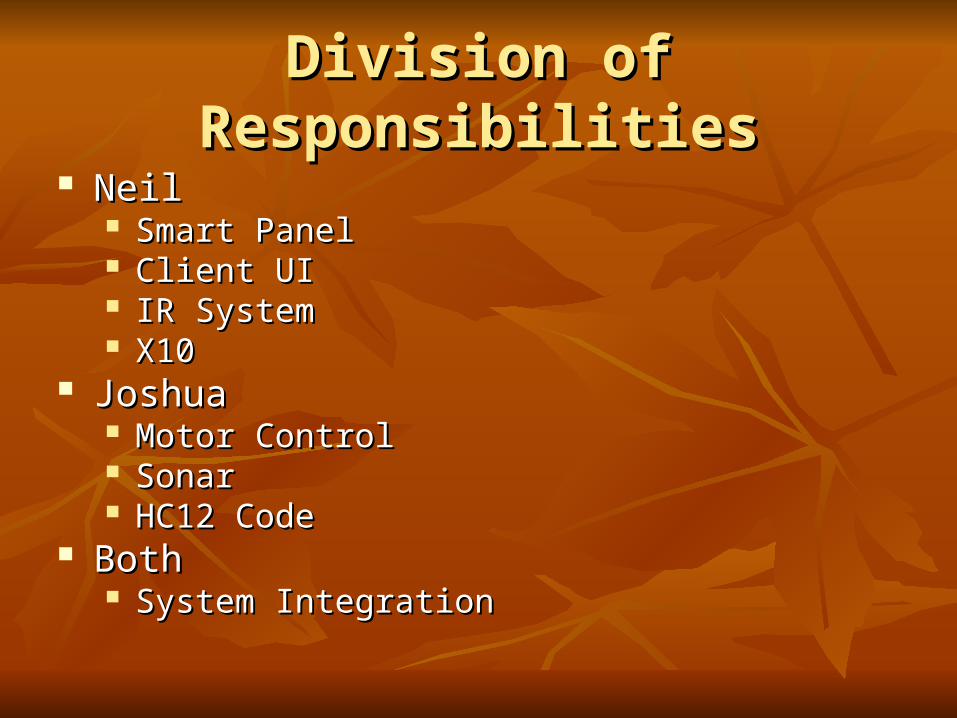
Division of ResponsibilitiesDivision of Responsibilities NeilNeil
Smart PanelSmart Panel Client UIClient UI IR SystemIR System X10X10
JoshuaJoshua Motor ControlMotor Control SonarSonar HC12 CodeHC12 Code
BothBoth System IntegrationSystem Integration
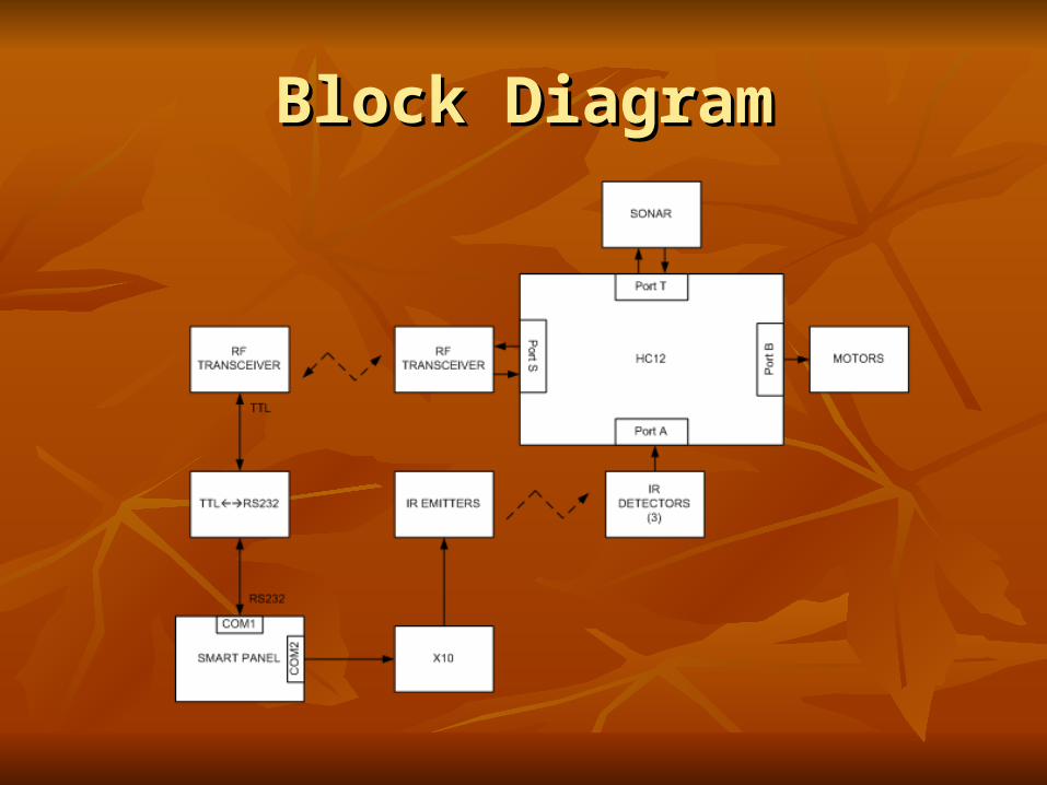
Block DiagramBlock Diagram

High-level Software DesignHigh-level Software Design
User-Interface Responsibilities:User-Interface Responsibilities: Displaying all home dataDisplaying all home data
device statusdevice status robot positionrobot position
Relaying user-commands to Smart PanelRelaying user-commands to Smart Panel Smart Panel Responsibilities:Smart Panel Responsibilities:
Maintaining home persistency dataMaintaining home persistency data Robot NavigationRobot Navigation Issuing X10 commandsIssuing X10 commands
Client User Interface
Smart Panel(Home Server)

User-InterfaceUser-Interface
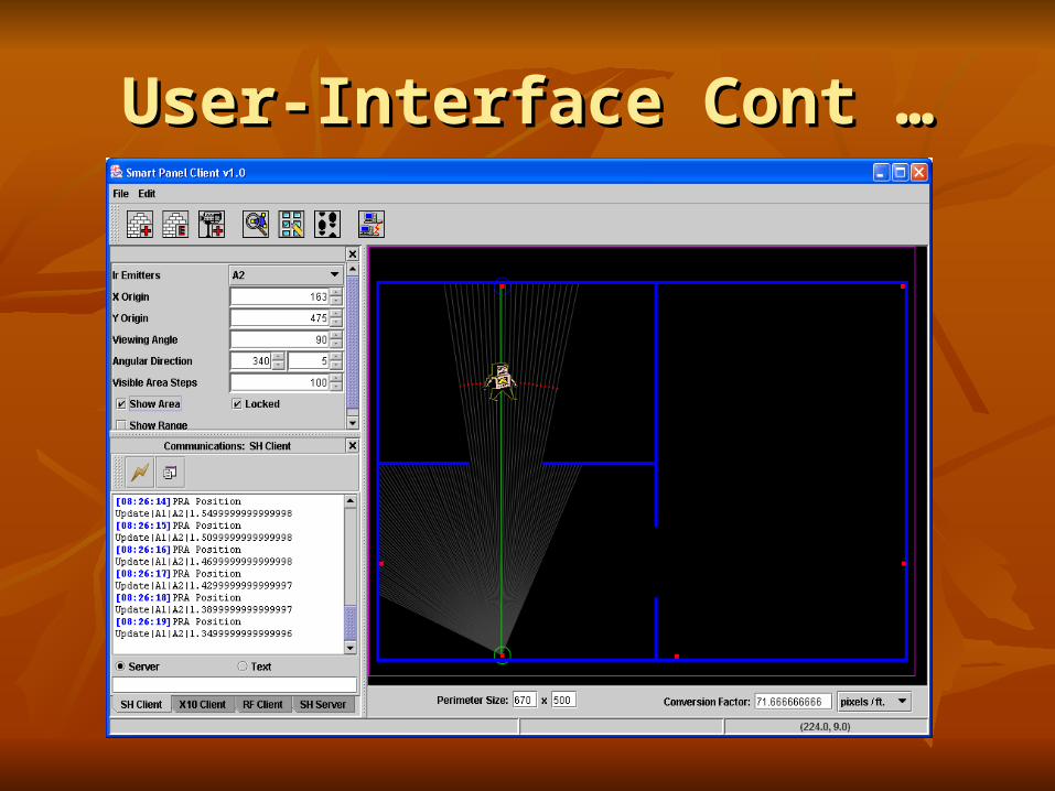
User-Interface Cont …User-Interface Cont …

IR SystemIR System Ir EmittersIr Emitters
940 nm wavelength940 nm wavelength 180180° viewing area° viewing area
Ir Detection ModulesIr Detection Modules 940 nm wavelength940 nm wavelength 100100° detection area° detection area
Double Modulated IRDouble Modulated IR 38 kHz carrier frequency38 kHz carrier frequency 300 Hz signal frequency300 Hz signal frequency
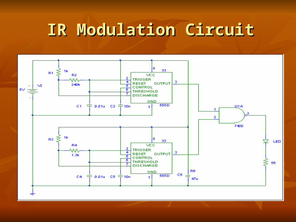
IR Modulation CircuitIR Modulation Circuit
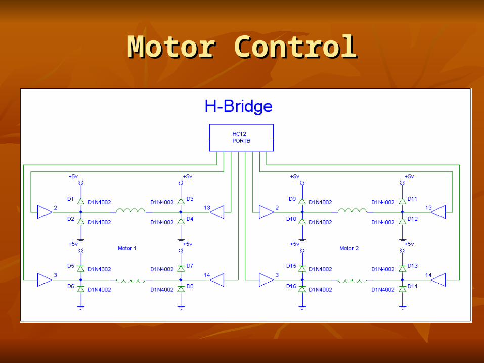
Motor ControlMotor Control

Power ConsumptionPower Consumption
Two separate power sourcesTwo separate power sources 2400 mAh RC battery pack2400 mAh RC battery pack
Stepper motor power supply uses 6 VDCStepper motor power supply uses 6 VDC Draws 2A max (2.2A x 6V = 13.2W)Draws 2A max (2.2A x 6V = 13.2W) 13.2 Watt Power Consumption13.2 Watt Power Consumption
9 VDC9 VDC HC12, RF module, IR detectors, sonar moduleHC12, RF module, IR detectors, sonar module Draws 180mA (180mA x 5V = 0.9W)Draws 180mA (180mA x 5V = 0.9W) 0.9 Watt Power Consumption0.9 Watt Power Consumption

Current ProgressCurrent Progress
Server “Smart Panel” – 90%Server “Smart Panel” – 90% Client Software Program – 90%Client Software Program – 90% RF Communication – 90%RF Communication – 90% Motor Control – 75%Motor Control – 75% Sonar System – 75%Sonar System – 75% IR System – 75%IR System – 75% System Integration – 25 %System Integration – 25 % Test/Debugging – 25%Test/Debugging – 25%

Basic Test PlanBasic Test Plan
1)1) Place PRA device in start position of Room APlace PRA device in start position of Room A2)2) Select Room C as the destination using the Select Room C as the destination using the
client applicationclient application3)3) Start movement of PRA by clicking “GO” on Start movement of PRA by clicking “GO” on
client applicationclient application1)1) PRA moves from start to A2PRA moves from start to A22)2) A2 to B1A2 to B13)3) B1 to B2B1 to B24)4) B2 to C1B2 to C1
Basic Test Plan Cont…Basic Test Plan Cont…
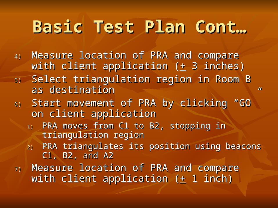
4)4) Measure location of PRA and compare with client Measure location of PRA and compare with client application (application (++ 3 inches) 3 inches)
5)5) Select triangulation region in Room B as destinationSelect triangulation region in Room B as destination6)6) Start movement of PRA by clicking “GO” on client Start movement of PRA by clicking “GO” on client
applicationapplication1)1) PRA moves from C1 to B2, stopping in triangulation PRA moves from C1 to B2, stopping in triangulation
regionregion2)2) PRA triangulates its position using beacons C1, B2, and PRA triangulates its position using beacons C1, B2, and
A2A2
7)7) Measure location of PRA and compare with client Measure location of PRA and compare with client application (application (++ 1 inch) 1 inch)

Test Plan LayoutTest Plan Layout
System CostSystem Cost
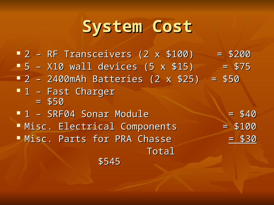
2 – RF Transceivers (2 x $100) = $2002 – RF Transceivers (2 x $100) = $200 5 – X10 wall devices (5 x $15) = $755 – X10 wall devices (5 x $15) = $75 2 – 2400mAh Batteries (2 x $25) = $502 – 2400mAh Batteries (2 x $25) = $50 1 – Fast Charger = $501 – Fast Charger = $50 1 – SRF04 Sonar Module = $401 – SRF04 Sonar Module = $40 Misc. Electrical Components = $100Misc. Electrical Components = $100 Misc. Parts for PRA Chasse Misc. Parts for PRA Chasse = $30= $30 Total $545Total $545

Potential ProblemsPotential Problems
Stepper Motor TorqueStepper Motor Torque Still may not be reliable enoughStill may not be reliable enough Change Castor wheelChange Castor wheel Switch to standard DC motorsSwitch to standard DC motors
IR AccuracyIR Accuracy Need to minimize “detection cones”Need to minimize “detection cones”
RF CommunicationRF Communication Interference detected in the labInterference detected in the lab
Code Space on HC12Code Space on HC12 Only 20% leftOnly 20% left

Questions?Questions?
Comments?Comments?
Related Documents