Boston Properties The Link Exterior and Wayfinding Signage Design Development 3.19.19 Bulletin 2

Welcome message from author
This document is posted to help you gain knowledge. Please leave a comment to let me know what you think about it! Share it to your friends and learn new things together.
Transcript

Boston PropertiesThe LinkExterior and Wayfinding Signage
Design Development
3.19.19
Bulletin 2
G.2
Leverage Design Group, Inc. © 2019
No portion of this drawing may be reproduced
without written consent of Leverage Design Group,
Inc. The design elements represented on this sheet
and related sheets are for design intent only.
Leverage Design Group, Inc. does not represent that
the design of the elements on the sheets are able to
be fabricated entirely as shown. Contractor/fabricator
to review documents for contractibility, performance
and structural soundness and to notify Leverage
Design Group, Inc. in the event of concern or
disagreement with the contractibility and design
intent of the elements as depicted on the sheets.
Boston Properties
The Link
1
2
3
4
5
6
7
REV # DESCRIPTION BY DATE
ProjectStandards
Signage Typography
T1- Gotham Medium
Magenta
Light Teal BrushedAluminum
Dark Teal
P1 P2
V1
P3
Sinage Project Materials
Acrylic
A1
TranslucentWhite Vinyl
V2
3M 7725-020Matte White Vinyl
V3
Frosted Acrylic
A2
White Light Magenta
P4 P5
Dark Magenta
P6
MetalM1
Signage Logos
ABCDEFGH I JKLMNOPQRSTUVWXYZabcde fgh i j k lmnopq r s t u vwxyz1 2 34567890
T2- Avenir Next Bold
A B C D E F G H I J K L M N O P Q R S T U V W X Y Za b c d e f g h i j k l m n o p q r s t u v w x y z1 2 3 4 5 6 7 8 9 0
G.3
Leverage Design Group, Inc. © 2019
No portion of this drawing may be reproduced
without written consent of Leverage Design Group,
Inc. The design elements represented on this sheet
and related sheets are for design intent only.
Leverage Design Group, Inc. does not represent that
the design of the elements on the sheets are able to
be fabricated entirely as shown. Contractor/fabricator
to review documents for contractibility, performance
and structural soundness and to notify Leverage
Design Group, Inc. in the event of concern or
disagreement with the contractibility and design
intent of the elements as depicted on the sheets.
Boston Properties
The Link
1
2
3
4
5
6
7
REV # DESCRIPTION BY DATE
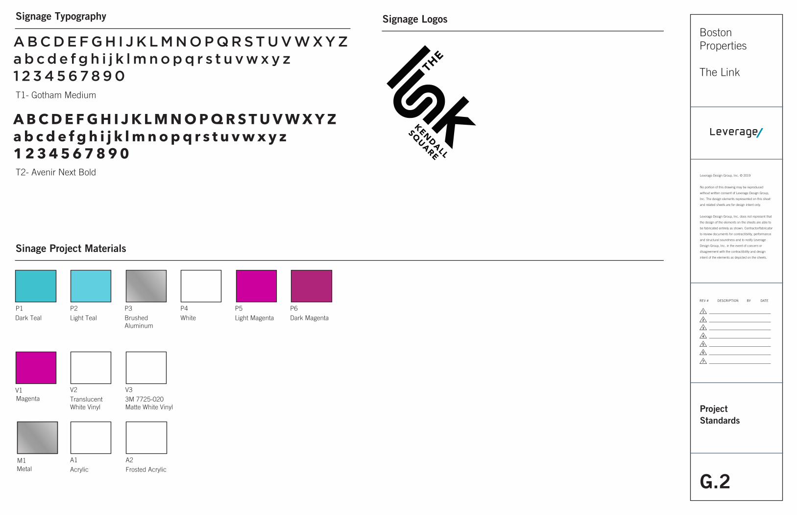
B1Exterior Vinyl Signage
1Elevationscale: 1/2” = 1’-0”
SECOND SURFACE APPLIED VINYL LOGOVINYL TO MATCH3M 7725-020 MATTE WHITE
V3
2'-4"
3'-4
"3
'-0"
3’ x 3’ SURFACE APPLIED VINYL
1Elevationscale: NTS
G.4
Leverage Design Group, Inc. © 2019
No portion of this drawing may be reproduced
without written consent of Leverage Design Group,
Inc. The design elements represented on this sheet
and related sheets are for design intent only.
Leverage Design Group, Inc. does not represent that
the design of the elements on the sheets are able to
be fabricated entirely as shown. Contractor/fabricator
to review documents for contractibility, performance
and structural soundness and to notify Leverage
Design Group, Inc. in the event of concern or
disagreement with the contractibility and design
intent of the elements as depicted on the sheets.
Boston Properties
The Link
1
2
3
4
5
6
7
REV # DESCRIPTION BY DATE
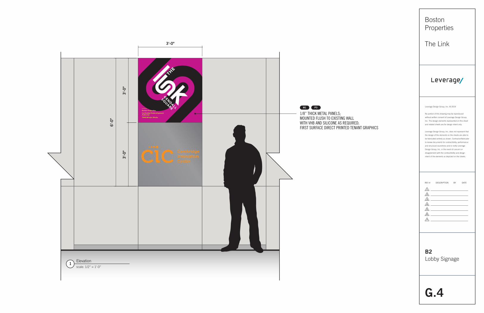
B2Lobby Signage
SPONSERED BY
Boston PropertiesCambridge RedevelopmentAuthorityTSNE Mission Works
1Elevationscale: 1/2” = 1’-0”
1/8” THICK METAL PANELS;MOUNTED FLUSH TO EXISTING WALLWITH VHB AND SILICONE AS REQUIRED; FIRST SURFACE DIRECT PRINTED TENANT GRAPHICS
M1 P3
6'-0
"
3'-0"
3'-0
"3
'-0"
G.5
Leverage Design Group, Inc. © 2019
No portion of this drawing may be reproduced
without written consent of Leverage Design Group,
Inc. The design elements represented on this sheet
and related sheets are for design intent only.
Leverage Design Group, Inc. does not represent that
the design of the elements on the sheets are able to
be fabricated entirely as shown. Contractor/fabricator
to review documents for contractibility, performance
and structural soundness and to notify Leverage
Design Group, Inc. in the event of concern or
disagreement with the contractibility and design
intent of the elements as depicted on the sheets.
Boston Properties
The Link
1
2
3
4
5
6
7
REV # DESCRIPTION BY DATE
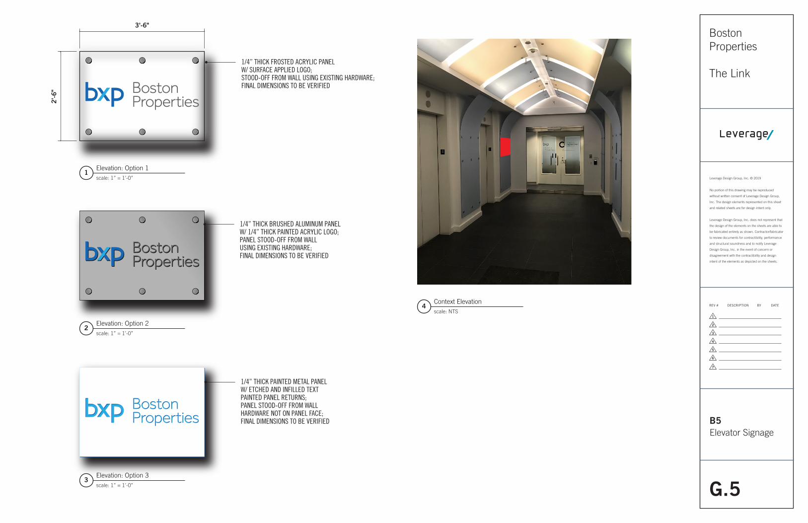
B5Elevator Signage
1/4” THICK FROSTED ACRYLIC PANELW/ SURFACE APPLIED LOGO;STOOD-OFF FROM WALL USING EXISTING HARDWARE;FINAL DIMENSIONS TO BE VERIFIED
1/4” THICK BRUSHED ALUMINUM PANELW/ 1/4” THICK PAINTED ACRYLIC LOGO;PANEL STOOD-OFF FROM WALLUSING EXISTING HARDWARE;FINAL DIMENSIONS TO BE VERIFIED
1/4” THICK PAINTED METAL PANELW/ ETCHED AND INFILLED TEXTPAINTED PANEL RETURNS;PANEL STOOD-OFF FROM WALLHARDWARE NOT ON PANEL FACE;FINAL DIMENSIONS TO BE VERIFIED
3Elevation: Option 3scale: 1” = 1’-0”
4Context Elevationscale: NTS
2Elevation: Option 2scale: 1” = 1’-0”
1Elevation: Option 1scale: 1” = 1’-0”
3'-6"
2'-6
"
G.6
Leverage Design Group, Inc. © 2019
No portion of this drawing may be reproduced
without written consent of Leverage Design Group,
Inc. The design elements represented on this sheet
and related sheets are for design intent only.
Leverage Design Group, Inc. does not represent that
the design of the elements on the sheets are able to
be fabricated entirely as shown. Contractor/fabricator
to review documents for contractibility, performance
and structural soundness and to notify Leverage
Design Group, Inc. in the event of concern or
disagreement with the contractibility and design
intent of the elements as depicted on the sheets.
Boston Properties
The Link
1
2
3
4
5
6
7
REV # DESCRIPTION BY DATE
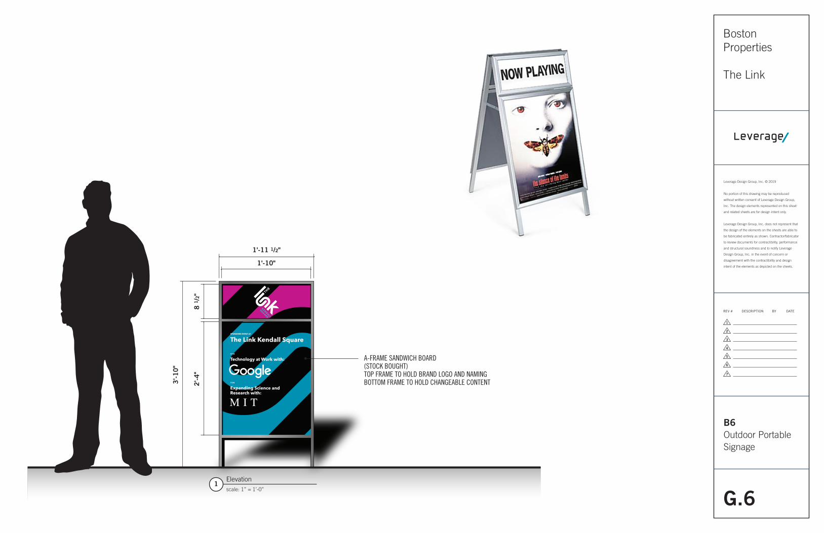
B6Outdoor Portable Signage
SPONSERED EVENT AT:
The Link Kendall Square
7/10
Technology at Work with:
7/24
Expanding Science andResearch with:
1Elevationscale: 1” = 1’-0”
A-FRAME SANDWICH BOARD(STOCK BOUGHT)TOP FRAME TO HOLD BRAND LOGO AND NAMINGBOTTOM FRAME TO HOLD CHANGEABLE CONTENT
1'-10"
1'-11 1/2"
8 1
/2"
2'-4
"
3'-1
0"
G.7
Leverage Design Group, Inc. © 2019
No portion of this drawing may be reproduced
without written consent of Leverage Design Group,
Inc. The design elements represented on this sheet
and related sheets are for design intent only.
Leverage Design Group, Inc. does not represent that
the design of the elements on the sheets are able to
be fabricated entirely as shown. Contractor/fabricator
to review documents for contractibility, performance
and structural soundness and to notify Leverage
Design Group, Inc. in the event of concern or
disagreement with the contractibility and design
intent of the elements as depicted on the sheets.
Boston Properties
The Link
1
2
3
4
5
6
7
REV # DESCRIPTION BY DATE
B6Outdoor Portable Signage
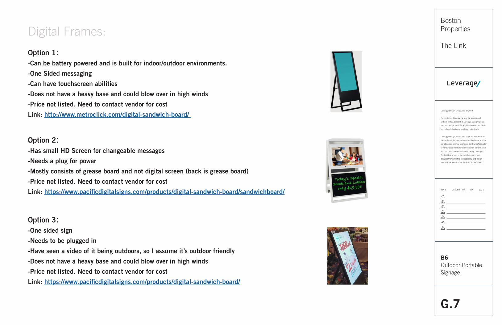
Option 1: -Can be battery powered and is built for indoor/outdoor environments.
-One Sided messaging
-Can have touchscreen abilities
-Does not have a heavy base and could blow over in high winds
-Price not listed. Need to contact vendor for cost
Link: http://www.metroclick.com/digital-sandwich-board/
Option 2: -Has small HD Screen for changeable messages
-Needs a plug for power
-Mostly consists of grease board and not digital screen (back is grease board)
-Price not listed. Need to contact vendor for cost
Link: https://www.pacificdigitalsigns.com/products/digital-sandwich-board/sandwichboard/
Option 3: -One sided sign
-Needs to be plugged in
-Have seen a video of it being outdoors, so I assume it’s outdoor friendly
-Does not have a heavy base and could blow over in high winds
-Price not listed. Need to contact vendor for cost
Link: https://www.pacificdigitalsigns.com/products/digital-sandwich-board/
Digital Frames:
G.8
Leverage Design Group, Inc. © 2019
No portion of this drawing may be reproduced
without written consent of Leverage Design Group,
Inc. The design elements represented on this sheet
and related sheets are for design intent only.
Leverage Design Group, Inc. does not represent that
the design of the elements on the sheets are able to
be fabricated entirely as shown. Contractor/fabricator
to review documents for contractibility, performance
and structural soundness and to notify Leverage
Design Group, Inc. in the event of concern or
disagreement with the contractibility and design
intent of the elements as depicted on the sheets.
Boston Properties
The Link
1
2
3
4
5
6
7
REV # DESCRIPTION BY DATE
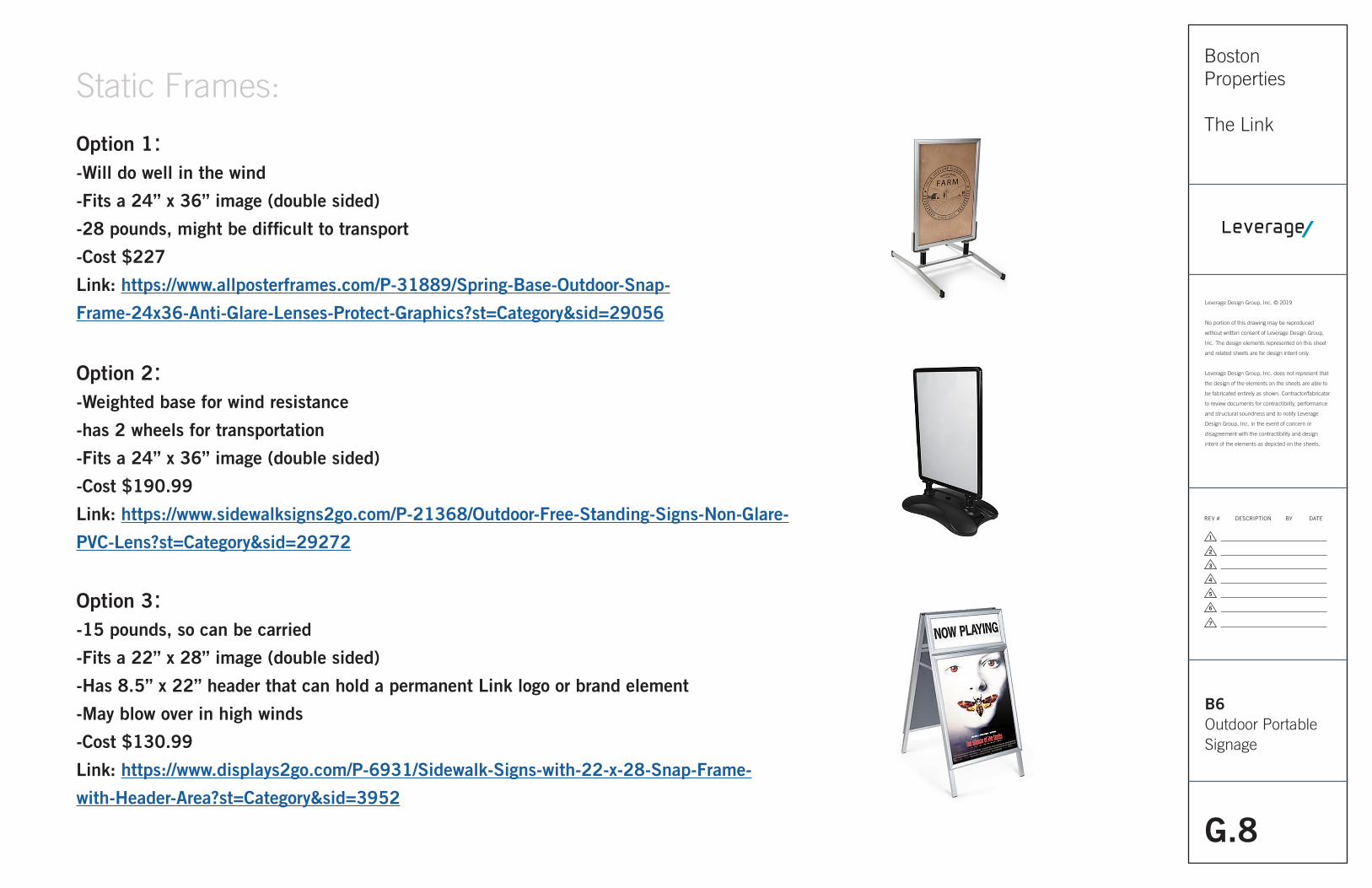
B6Outdoor Portable Signage
Option 1: -Will do well in the wind
-Fits a 24” x 36” image (double sided)
-28 pounds, might be difficult to transport
-Cost $227
Link: https://www.allposterframes.com/P-31889/Spring-Base-Outdoor-Snap-
Frame-24x36-Anti-Glare-Lenses-Protect-Graphics?st=Category&sid=29056
Option 2: -Weighted base for wind resistance
-has 2 wheels for transportation
-Fits a 24” x 36” image (double sided)
-Cost $190.99
Link: https://www.sidewalksigns2go.com/P-21368/Outdoor-Free-Standing-Signs-Non-Glare-
PVC-Lens?st=Category&sid=29272
Option 3: -15 pounds, so can be carried
-Fits a 22” x 28” image (double sided)
-Has 8.5” x 22” header that can hold a permanent Link logo or brand element
-May blow over in high winds
-Cost $130.99
Link: https://www.displays2go.com/P-6931/Sidewalk-Signs-with-22-x-28-Snap-Frame-
with-Header-Area?st=Category&sid=3952
Static Frames:
G.9
Leverage Design Group, Inc. © 2019
No portion of this drawing may be reproduced
without written consent of Leverage Design Group,
Inc. The design elements represented on this sheet
and related sheets are for design intent only.
Leverage Design Group, Inc. does not represent that
the design of the elements on the sheets are able to
be fabricated entirely as shown. Contractor/fabricator
to review documents for contractibility, performance
and structural soundness and to notify Leverage
Design Group, Inc. in the event of concern or
disagreement with the contractibility and design
intent of the elements as depicted on the sheets.
Boston Properties
The Link
1
2
3
4
5
6
7
REV # DESCRIPTION BY DATE
1.0 DESIGNER’S RESPONSIBILITIES
A Review & Approval
1. Attention is directed to the fact that Designer review is only to check for general conformancewith the design concept of the project and general compliance with Design Documents.No responsibility is assumed by Designer for correctness of dimensions, details, quantities,procedures shown on shop drawings, or submittals.
2. It shall be the responsibility of the Designer to review all fabricator submittals with reasonablepromptness on basis of design concept of project and information contained in DesignDocuments.
3. Omission in shop drawings of materials indicated in Design Documents mentioned inSpecifications, or required for proper execution and completion of work, does not relievethe Fabricator from responsibility for providing such materials. Fabricator is responsible foraccuracy, dimensions, quantities, strength of connection, coordination with various trades, andconformance to project requirements.
4. Approval of a separate or specified item does not necessarily constitute approval of anassembly in which the item is a part of.
5. It shall be the responsibility of the Designer to review to affix stamp and initials or signatureacknowledging review of submittal as follows: As Noted, Revise & Resubmit, Rejected,For Info Only
B Artwork
1. Designer to provide artwork digitally via Adobe Illustrator
2. 0 FABRICATOR’S RESPONSIBILITIES
A General
1. It shall be the responsibility of the Fabricator that all finished work be of the highest quality topass eye-level examination and scrutiny by the Client and Designer.
2. It shall be the responsibility of the Fabricator to fabricate and install all sign types, messagesand graphics as indicated in the Design Documents.
3. It shall be the responsibility of the Fabricator to assist and collaborate with all Clients teams,agencies, sub-contractors (as needed) and Designer to complete project scope.
4. It shall be the responsibility of the Fabricator to provide, manage and maintain project fabrication andinstallation schedules and to provide updates to these schedules as needed to Client andDesigner.
5. It shall be the responsibility of the fabricator to provide timely notice to Client and Designerfor submittals of information, drawings and other details needed to meet fabrication andinstallation schedule.
B Structural Design
1. Details on Drawings indicate a design approach for sign fabrication but do not necessarilyinclude all fabricating details required for the complete structural integrity of the signs,including consideration for static, dynamic, and erection loads during handling, erecting, andservice at the installed locations, nor do they necessarily consider the preferred shop practicesof the individual sign fabricators. Therefore, it shall be the responsibility of the Fabricatorto perform the complete structural design of the signs and to incorporate all the reasonable
safety factors necessary to protect the Client, its representatives, and Designer against publicliability.
2. Designs which survive rational engineering analysis will be acceptable, provided that shopdrawings, including structural design, are approved by the Client and Designer.
C Code Compliance
1. It shall be the responsibility of the Fabricator to ensure that all signs meet all applicable local,state, and national codes, as well as testing laboratory listings where required.
D Samples
1. Allow 5 business days for the Client and Designer to review and process samples
2. The Fabricator shall submit physical samples of sufficient size and quantity to illustratecolor, materials, finishes, equipment or workmanship, and to establish standards by which completedwork will be judged. Samples must represent the functional characteristics of the product ormaterial, with integrally related parts and attachment devices, colors, and finishes.
3. All samples to have a place for stamp approval.
4. Submit (2) complete sets of samples to Designer for review.
5. Submit (1) complete set of samples for Client review.
6. Submit full 6” x 6” set of all specified paint colors and finishes on specified materials.
7. Submit sample of each type of fastener to be used, as required.
8. Submit other items as may be required by Client and Designer, or as noted on the drawings orherein.
E Prototypes
1. Submit prototypes as may be required by Client and Designer, or as noted on the drawings orherein.
F Shop Drawings
1. Allow 5 business days for the Client and Designer to review and process shop drawings.
2. The drawings in this package are for design intent only. The Fabricator is responsible for theproper engineering of all items and verification on site of all installation requirements.
3. Provide shop drawings for all items in the Design Documents.
4. Provide (2) complete sets of shop drawings to Designer for review. Allow 5 business days forproper review of Shop Drawings by Designer.
5. Provide (1) complete set of shop drawings to Client for review.
6. Provide internal structure, dimensions, and specifications for all items in the Design Documents.
7. Provide all structural, stamped engineering drawings by licensed engineer in state whereproject will be installed.
8. Provide fabrication and installation drawings for each sign type. Indicate dimensions, materials,finishes, fastening, anchorage, joining, sealing, backing, utility requirements, rough-in, andadjacent related site conditions.
PerformanceSpecifications
G.10
Leverage Design Group, Inc. © 2019
No portion of this drawing may be reproduced
without written consent of Leverage Design Group,
Inc. The design elements represented on this sheet
and related sheets are for design intent only.
Leverage Design Group, Inc. does not represent that
the design of the elements on the sheets are able to
be fabricated entirely as shown. Contractor/fabricator
to review documents for contractibility, performance
and structural soundness and to notify Leverage
Design Group, Inc. in the event of concern or
disagreement with the contractibility and design
intent of the elements as depicted on the sheets.
Boston Properties
The Link
1
2
3
4
5
6
7
REV # DESCRIPTION BY DATE
9. Submit, color production artwork of all sign messages in each typeface to demonstrate properspacing (black text on white background, outline not accepted) prior to fabrication.
10. Indicate revisions date as required, and resubmit as specified for initial submittal.
11. Indicate on drawings all changes that are different than those requested by the Designer.
12. Submit new data and samples in accord with same criteria as required for first submittals.
G Product Data
1. Submit product data for sign systems, fixtures, material descriptions, components, standardprofiles, and finishes.
2. Submit Color charts for finish indicating manufacturer’s colors available for selection.
3. Include sample of warranty.
H Inspection
1. Client and Designer reserve the right to inspect work in the fabrication shopbefore it is shipped to the job site for installation.
2. Fabricator shall inspect installation locations for conditions which will adverselyaffect execution, permanence and quality of work, and shall not proceed with installation untilunsatisfactory conditions have been corrected.
3. First article of production-run items, both large and small, will be reviewed by the Client andDesigner before production run is commenced.
I Installation
1. Installation of all fabricated signs, including all fasteners and fastenings and related electricalconnections; all foundations for all signs in Design Documents
2. Coordination with Client and Designer during all phases of development, fabrication, andinstallation.
3. Coordination with other trades, i.e., electrical contractors, etc.
4. Coordination and verification of all messages revisions with Client.
5. Verify the exact location with the Designer and Client for all signs which are not preciselydimensioned on the Drawings.
6. Except as may be specifically indicated otherwise on the drawings, install prefabricated workplumb, level, square, and true to line.
7. Securely anchor work in proper location using anchors, fasteners, or other methods approvedon shop and erection drawings. All anchors/fasteners shall be appropriate for the anchoragecondition.
J Fabrication
1. Construct all work to eliminate burrs, dents, cutting edges, and sharp corners.
2. Finish welds on exposed surfaces to be imperceptible in the finished work.
3. Except as indicated or directed otherwise, finish all surfaces smooth.
4. Surfaces which are intended to be flat shall be without dents, bulges, oil canning, gaps, orother physical deformities.
5. Surfaces which are intended to be curved shall be smoothly free-flowing to required shapes.
6. Except where approved otherwise by Designer, or specified in the Design Documents, concealor counter-sink all fasteners.
7. Make access panels tight-fitting, lightproof, and flush with adjacent surfaces.
8. Conceal all identification labels and U.L. labels to conform to U.L. Codes.
9. Carefully follow manufacturer’s recommended fabricating procedures regarding expansion/contraction, fastening, and restraining of acrylic plastic.
10. Exercise care to assure that painted, polished, and plated surfaces are unblemishedin the finished work.
11. Isolate dissimilar materials. Exercise particular care to isolate nonferrous metalsfrom ferrous metals.
12. All illumination shall be even and without hotspots.
13. Ease all exposed metal edges.
K Punch List
1. When Fabricator considers the work has reached final completion (that is, when less thanone percent of the Contract remains to be completed), submit written notice, together with awritten list of items to be completed or corrected.
2. The Client and Designer will inspect the status of completion and prepare a “Punch List” settingforth in detail any items on the Fabricator’s list and additional items found unacceptable. Whenthe Punch List is complete, the Client will arrange a meeting with the Fabricator to identify andexplain all items and respond to questions regarding the work which must be done before finalacceptance.
3. Fabricator shall correct Punch List items within a time frame established when the punchlist is made. The time frame for completion of the Punch List items shall not exceed thecompletion date of the Contract. The Contract shall not be considered complete until PunchList items are completed.
3.0 PRODUCTS
A Metal
1. Sheet Aluminum: Alloy 5000 Series for anodized finish; Alloy 3000 Series for painted finish.2. Extruded Aluminum: ASTM B221M, alloy 6063-T5/T52.3. Stainless Steel Pipe: ASTM A312/A312M, Grade TP3044. Stainless Steel Pipe Sheets: ASTM A240, UNS Number S30200 or S30400.5. Steel Tubing: ASTM A500 or A5016. Steel Plates, Shapes and Bars: ASTM A36/A36M.7. Structural Steel Sheet: Hot-rolled, ASTM A570/A570M, [Cold-rolled ASTM A611,] Class 1;of grade required for design loading.8. Cold-Rolled Steel Sheet, Commercial Quality: ASTM A366/A366M.9. Metal thickness indicated establishes minimum conditions.10. When metal thickness is not indicated, provide thickness most appropriate for Project conditionto prevent oil canning and warping, but not less than following: a. Sheet steel [Galvanized]: 1 mm [(20 gage)] nominal thickness.
PerformanceSpecifications
G.11
Leverage Design Group, Inc. © 2019
No portion of this drawing may be reproduced
without written consent of Leverage Design Group,
Inc. The design elements represented on this sheet
and related sheets are for design intent only.
Leverage Design Group, Inc. does not represent that
the design of the elements on the sheets are able to
be fabricated entirely as shown. Contractor/fabricator
to review documents for contractibility, performance
and structural soundness and to notify Leverage
Design Group, Inc. in the event of concern or
disagreement with the contractibility and design
intent of the elements as depicted on the sheets.
Boston Properties
The Link
1
2
3
4
5
6
7
REV # DESCRIPTION BY DATE
b. Aluminum: 3.125 [2.25] mm [(0.125 [0.090] inch)] thickness minimum. c. Stainless Steel: 1 mm [(20 gage)] nominal thickness. d. Muntz Metal: Nominal 2.5 mm [(7.2 ounce)] thick.
B Plastic
1. Photopolymer: Exterior grade consisting of 1/32 inch thick exterior grade photopolymer layerof PVA/urethane base over integral layer of 1/8 inch thick phenolic base plate.2. Minimum 90 to 95 Shore ‘D’ Hardness.
3. Braille: Maximum surface diameter of 0.30 inch rounded.
C Acrylic
1. Material: Methylmethacrylate polymers.
2. Type: Solid sheet, laminated sheet, or cast acrylic in size, thickness, clarity, opacity, texture,and color required for Project.
D Silk Screening
1. Screen Material For Screen Printing Process: Stainless steel, nylon or polyester with 250 linesper inch, or finer
2. Use 16 XX screen for printing on cloth fabric.
3. Ink: Available in published color systems with full range of accent or pure spectrum colors,earth colors, and unlimited mixtures of colors.
4. Execute silk-screening from photoscreens, film positives, or developed negatives.
5. Execute silk-screen printing to ensure edges and corners of finished letter forms are true andclean. Letter forms with rounded positive or negative corners, edge buildup, or bleedings,voids, gaps, streaks, hot-spots, or other defects, will not be accepted.
6. Do not use inks which have been packaged over 6 months, except such products that areknown to have long package stability when unopened and then only when guaranteed by themanufacturer. Inks shall be free from skins, lumps, and foreign matter. Oils, thinners, anddriers delivered to the job shall be only those approved for use by the manufacturer.
E Adhesive Film
1. Computer Cut Vinyl Graphics: Pressure sensitive adhesive type; Thickness: 0.11 mm [(4.3mils)]; Spacing: Computer default for font selected, unless otherwise shown or scheduled.Optically review and refine kerning pairs to adjust spacing of letters for visual consistency;Color: As shown or scheduled.
F Illumination
1. Code: Conform to National Electrical Code for electrical and communication components,materials, assemblies, and systems.
2. Lamps: a. Type: Provide wattages and lamp type required by use conditions to provide uniform illumination with no hot spots or dim surfaces. b. Neon: 5 mm [(3/16 inch)] to 25 mm [(1 inch)] glass tubing as determined by design. c. Color: As selected by Designer d. Transformers: Provide 60 MA transformers for neon units.
3. Ballasts: High power factor type as required by work conditions.
4. Disconnects: a. Type: Enclosed, heavy duty, fused or unfused.
5. Locations: Provide NEMA 1 for dry locations and proper enclosure for others.
6. Conductors: THHN, No. 12.
7. Accessories: Provide supports, hangers, and other accessories as required.
G Routing
1. Water jet. High pressure water jet adjustable for cut-outs and for engraving surfaces.
2. Machine routing.
H Fabrication Aluminum Cabinets And Pan-Formed Panels
1. Aluminum sign cabinets: Aluminum signs shall be fabricated from cold rolled pattern leveledsheet aluminum, conforming to ASTM B209, Alloy No. 5005H32. Each panel shall be shopformed in dies from a single sheet of material. Corners shall be coped, continuous heliarcwelded, and ground smooth on exposed faces.
2. Illuminated messages shall be cut from aluminum by means of an automated cutting system.
3. Integrity: Execute messages in such a manner that edges and corners of finished letter formsare true and clean. Letter forms with round positive or negative corners, non-uniform strokewidths, nicks, cuts, or ragged edges will not be acceptable.
I Fabrication Individual Letters, Numbers And Logos
1. Pin-mounted Aluminum Welded Construction: Alloy 5005 H14, 3.125 [2.25] mm [(0.125[0.090] inch)] thickness minimum unless noted otherwise.
2. Mounting distance from wall surface: As shown.
3. Depth of returns: As shown.
J Paints, Coatings, & Finishes1. Paint Color References: Color references are for color designation only. Refer to Schedule atend of Section for applicable coating systems. Colors which may be indicated on Drawingsinclude: a. PMS: Pantone Matching System. b. MAP (Matthews Acrylic Polyurethane): Matthews Paint Company. c. HC: Benjamin Moore Historic colors. d. BM: Benjamin Moore. e. Lacryl: Spraylat Corporation.
2. Paint Formulation: Formulate paint materials with antimildew agents and carefully balanceultraviolet inhibitors for exterior materials.
3. Application: a. Properly prepare subsurfaces and apply materials in sanitary environment. b. Apply materials by method (brush, roller, spray) best suited to obtain required finish matching approved samples. c. Ensure finish surfaces are free of brush marks, streaks, laps, runs, or pileup of paints, with uniform coverage.
4. Unless indicated otherwise, provide a satin finish.
PerformanceSpecifications
Related Documents