Extending UML 2.0 to Augment Control over Enterprise Information System Engineering Process M. Nikolaidou 1 , N. Alexopoulou 12 , A. Tsadimas 1 , A. Dais 1 , D. Anagnostopoulos 1 {[email protected], [email protected], [email protected], [email protected], [email protected]} 1 Harokopio University of Athens, 2 Department of Informatics and Telecommunications, El. Venizelou Str, 17671Athens, Greece University of Athens, Panepistimiopolis, 15771, Athens, Greece Abstract Enterprise Information Systems can be described according to the Open Distributed Processing Reference Model (RM-ODP), where five different viewpoints are specified analyzing various aspects of the system. Configuration issues are explored in the Engineering Viewpoint of RM-ODP. In practice, configuration issues are explored in discrete stages, supported by autonomous software tools, each of which adopts its own metamodel for system representation. We propose a platform independent framework, which focuses on the Engineering Viewpoint of Enterprise Information Systems managing application configuration and network design issues independently of application development progress. In order to apply this framework using existing tools, model exchangeability and tool coordination must be supported by standard, open methods. Thus, a common metamodel is proposed to generate enterprise information system models, which are stored in XML. A UML 2.0 profile is defined to visualize these models, facilitate the designer to interact with them and coordinate specific tool invocation. 1. Introduction The Open Distributed Processing Reference Model (RM-ODP) offers a conceptual framework integrating aspects related to the distribution, interoperation and portability of software systems in such a way that hardware infrastructure is transparent to the user. RM- ODP manages system internal complexity through the “separation of concerns”, addressing specific problems dealt with during system development from different viewpoints [1]. Five generic and complementary viewpoints are provided: Enterprise, Information, Computational, Engineering and Technology. The Enterprise Distributed Object Computing (EDOC) UML profile by OMG proposes system models to designers using UML concepts for the five viewpoints of RM- ODP framework. The Engineering Viewpoint focuses on system configuration issues, such as the type of system architecture (e.g. client-server), the definition of the system access points, the description of the underlying network architecture and the association of software components to network nodes (resource allocation). Although these issues are interrelated, they are often modeled using discrete views and studied in isolation, applying the concept of “separation of concerns” within the limits of the Engineering Viewpoint as well [2, 3]. This results in designing systems with poor system performance. In practice, discrete issues, as network architecture description or resource allocation are supported by autonomous automated or semi-automated tools [4, 5, 6], each of which adopts its own metamodel for system representation. Thus, no interaction between them is supported. In order to effectively explore the Engineering Viewpoint of Enterprise Information Systems, heterogeneous tools and system models should be integrated. Thus, tool coordination and internal metamodel transformation should be supported. The main advantage of the methodology proposed in [7] for web-based system configuration is the adoption of a common metamodel for the representation of systems throughout all configuration stages, ensuring interoperability and model consistency. Although, this is not feasible in the case of integrating autonomous software tools, an overall common metamodel can be adopted acting as a “reference point”, while partial transformations of the common metamodel into tool- specific metamodels may be also supported. In order to provide a consistent framework for enterprise system engineering the following issues should be addressed: • Definition of a common metamodel. • Integration of autonomous tools. • Model exchangeability and transformation. • Provision of an integrated, easy-to-use interface for the system designer. The proposed framework, which strictly focuses on the Engineering Viewpoint, deals with all these issues, ensuring strong control over the whole system 0-7695-2703-5/06/$20.00 (c) IEEE Proceedings of the International Conference on Software Engineering Advances (ICSEA'06) 0-7695-2703-5/06 $20.00 © 2006

Welcome message from author
This document is posted to help you gain knowledge. Please leave a comment to let me know what you think about it! Share it to your friends and learn new things together.
Transcript
Extending UML 2.0 to Augment Control over Enterprise Information System Engineering Process
M. Nikolaidou1, N. Alexopoulou12, A. Tsadimas1, A. Dais1, D. Anagnostopoulos1
{[email protected], [email protected], [email protected], [email protected], [email protected]} 1 Harokopio University of Athens, 2 Department of Informatics and Telecommunications, El. Venizelou Str, 17671Athens, Greece University of Athens, Panepistimiopolis, 15771, Athens, Greece
Abstract Enterprise Information Systems can be described according to the Open Distributed Processing Reference Model (RM-ODP), where five different viewpoints are specified analyzing various aspects of the system. Configuration issues are explored in the Engineering Viewpoint of RM-ODP. In practice, configuration issues are explored in discrete stages, supported by autonomous software tools, each of which adopts its own metamodel for system representation. We propose a platform independent framework, which focuses on the Engineering Viewpoint of Enterprise Information Systems managing application configuration and network design issues independently of application development progress. In order to apply this framework using existing tools, model exchangeability and tool coordination must be supported by standard, open methods. Thus, a common metamodel is proposed to generate enterprise information system models, which are stored in XML. A UML 2.0 profile is defined to visualize these models, facilitate the designer to interact with them and coordinate specific tool invocation.
1. Introduction The Open Distributed Processing Reference Model (RM-ODP) offers a conceptual framework integrating aspects related to the distribution, interoperation and portability of software systems in such a way that hardware infrastructure is transparent to the user. RM-ODP manages system internal complexity through the “separation of concerns”, addressing specific problems dealt with during system development from different viewpoints [1]. Five generic and complementary viewpoints are provided: Enterprise, Information, Computational, Engineering and Technology. The Enterprise Distributed Object Computing (EDOC) UML profile by OMG proposes system models to designers using UML concepts for the five viewpoints of RM-ODP framework. The Engineering Viewpoint focuses
on system configuration issues, such as the type of system architecture (e.g. client-server), the definition of the system access points, the description of the underlying network architecture and the association of software components to network nodes (resource allocation). Although these issues are interrelated, they are often modeled using discrete views and studied in isolation, applying the concept of “separation of concerns” within the limits of the Engineering Viewpoint as well [2, 3]. This results in designing systems with poor system performance. In practice, discrete issues, as network architecture description or resource allocation are supported by autonomous automated or semi-automated tools [4, 5, 6], each of which adopts its own metamodel for system representation. Thus, no interaction between them is supported. In order to effectively explore the Engineering Viewpoint of Enterprise Information Systems, heterogeneous tools and system models should be integrated. Thus, tool coordination and internal metamodel transformation should be supported. The main advantage of the methodology proposed in [7] for web-based system configuration is the adoption of a common metamodel for the representation of systems throughout all configuration stages, ensuring interoperability and model consistency. Although, this is not feasible in the case of integrating autonomous software tools, an overall common metamodel can be adopted acting as a “reference point”, while partial transformations of the common metamodel into tool-specific metamodels may be also supported. In order to provide a consistent framework for enterprise system engineering the following issues should be addressed: • Definition of a common metamodel. • Integration of autonomous tools. • Model exchangeability and transformation. • Provision of an integrated, easy-to-use interface for
the system designer. The proposed framework, which strictly focuses on
the Engineering Viewpoint, deals with all these issues, ensuring strong control over the whole system
0-7695-2703-5/06/$20.00 (c) IEEE
Proceedings of the International Conferenceon Software Engineering Advances (ICSEA'06)0-7695-2703-5/06 $20.00 © 2006
configuration process. The framework is presented in section 2. In section 3, we focus on the formal definition of a UML 2.0 Profile, facilitating the system engineering process. Conclusions reside in section 4.
2. EIS Engineering Framework The proposed EIS engineering framework facilitates 1) system requirements description, 2) resource (process/data) allocation and replication policy definition 3) network architecture design and 4) performance evaluation of the proposed solution (prior to implementation). As resource allocation and network design problems cannot be independently solved, stages (2) and (3) are repeatedly invoked until an acceptable solution is reached. The tools supporting them may be repeatedly invoked for different model abstraction levels [5], [6]. Since each of these tools supports its own representation metamodel (e.g. queuing networks, Petri-nets, objects), there is a need to properly create and instantiate the “internal” system model before invoking the tool. Input/output parameters must be represented in the common metamodel. Their values are either entered by the system designer or automatically computed. System requirements specification stage is performed through a UML 2.0 profile [8] for EIS engineering.
To ensure the consistency of the system model throughout all stages, the common metamodel is used as a “reference point”. It includes 3 alternative views. Functional View is used to describe functional specifications (e.g. system architecture, user behavior and application requirements). Application requirements are described in terms of quality of service (QoS) requirements imposed to the network infrastructure, e.g. amount of data processed, transferred or stored. Topology View facilitates the definition of system access points and the resource allocation and replication. Physical View refers to the aggregate network. Topology and Physical views are interrelated. Both are decomposed to the same hierarchical levels of detail. At the lowest level, network nodes are related to processes/data replicas. The metamodel itself contains relationships and restrictions inflicted between system entities belonging to the same or different views, which may lead to a specific stage invocation (e.g. if the network hierarchy in the physical view is modified, this modification must be depicted in the Topology View as well). The metamodel entities are presented in the next section through the profile description. Detailed description of the main entities can be found in [7].
Embedding restrictions within the metamodel enhances control over the EIS engineering process, taking into account the overall system model and not the specific system viewpoint corresponding to a discrete stage. As such, the framework facilitates both “separation” (through the definition of different views)
as well as “integration (through the definition of constraints representing interrelations between views) of concerns”. As a result, the overall process becomes more efficient, since it is divided into separate stages and thus is simplified, but at the same time the system configuration discrete stage (and corresponding tool) dependencies are depicted within the model as view dependencies and consequently they are easily identified. Furthermore, it becomes more efficient to integrate autonomous software tools in different levels of detail, as each of them is independently invoked without knowing the existence of others. All these result in the achievement of strong control over the whole system engineering process.
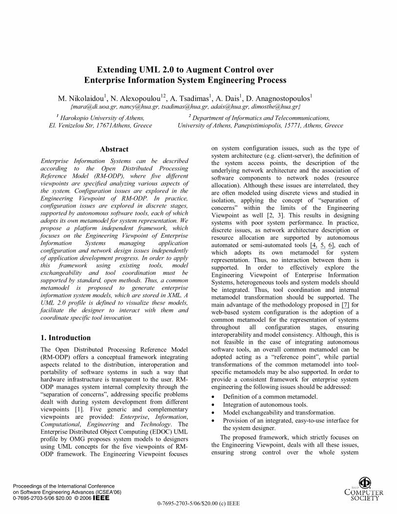
Figure 1. Metamodel Transformation Framework
To integrate an autonomous configuration tool in the EIS engineering framework, the following steps should be accomplished: Definition of a MOF-based representation of tool internal metamodel.
Transformation definition of common metamodel into tool internal metamodel and vise versa.
Automated creation/update of internal models, as XMI documents.
Import/export of internal XMI models into/out of the tool. These, as illustrated in figure 3, are performed
making use of Model Driven Architecture (MDA) concepts [9]. The common metamodel is defined based on Meta Object Facility (MOF). What is additionally required is the definition of a formal metamodel transformation to map UML metamodel entities (used for system graphical representation) to the common metamodel entities (used for system description) and vice versa. Likewise, a formal definition must be specified to map the common metamodel entities to
0-7695-2703-5/06/$20.00 (c) IEEE
Proceedings of the International Conferenceon Software Engineering Advances (ICSEA'06)0-7695-2703-5/06 $20.00 © 2006
those defined by the internal metamodel of each tool and vice versa. The proposed common metamodel is platform independent (PIM), while tool metamodels are platform specific (PSM). The transformation definitions are implied by the gray block arrows at the metamodel layer. The actual transformations are performed at the model layer. As shown at the implementation layer, the models are stored as XMI documents. The XMI document produced by any UML 2.0 tool, as Rational Modeler [10], using the EIS engineering profile, can be automatically translated into an XMI EIS model using an XSLT/Xquery processor and vise-versa. MDA suggests that transformations should be performed at model layer using formal definitions specified at the metamodel layer. In our current implementation though, we perform transformations using simple XSLT/Xquery rules for simplicity reasons. However, we indent to transfer the transformation process at the model layer in our future work.
3. UML 2.0 Profile Definition Notational aspects of the EIS metamodel are accommodated through a UML 2.0 profile. EDOC profile supports Engineering Viewpoint mainly using component diagrams for both the application configuration and the network infrastructure [2]. EIS entities are depicted as UML elements, properly extended to include additional properties and constraints. Thus, UML 2.0 stereotypes have been defined for each view, facilitating new attributes, constraints, and a new graphical representation. Essentially, the concepts of the common metamodel are reflected onto the stereotype attributes and constraints. Attributes convey the information required to describe EIS metamodel entities. Constraints, which are extensively used within the profile, represent relationships and restrictions between metamodel entities maintaining model consistency. Following, each view is described in detail. The proposed stereotypes are indicated in italics within parentheses next to the corresponding model element which is written in bold.
Functional View For each application operating in the EIS, a discrete Functional View is defined. Functional Views are represented as UML Component diagrams, as the latter are eligible for depicting system functionality at a logical level. Applications are conceived as sets of interacting modules. A module, which can be either server (ServerModuleComponent) or client (ClientModule Component) offers specific services (ServiceComponent). A Functional View usually includes a File Server module which is used for file storage. A server module service may be invoked (Invoke stereotype) by another one belonging to a different module. User behavior is described through
user profiles (UserProfileComponent) activating client modules. Each profile includes user requests (Initiate), which invoke specific services. The interaction between user profiles and services plays a determinative role in system engineering, since user profiles include performance requirements imposed by users. This is indicated by attributes of the UserProfileComponent and Initiate stereotypes. ActivationProbability attribute, for example, denotes how often a service is initiated while the user profile is active. Percentage attribute of Initiate stereotype indicates how often a specific service is activated by the profile. Functional View stereotypes are listed in Table 1 along with their attributes and constraints and their corresponding icons. Each stereotype has been named so that the first part of the name indicates the corresponding EIS metamodel entity, while the second part denotes the UML class it derives from. This doesn’t hold however for Initiate and Invoke stereotypes. These stereotypes are defined as a specialization of UML Dependency.
Concerning service implementation (ServiceActivity), it is represented through an activity diagram, as it involves flow of operations. Each ServiceActivity maps to a ServiceComponent, thus these two stereotypes have the same attributes. Service implementation consists of simple tasks occurring upon module activation, called operations (OperationAction). These are selected from a predefined operation set, that is, the Operation Dictionary. Operation Dictionary facilitates the decomposition of operations into elementary ones, i.e. processing, storing and transferring, so that QoS required from the underlying network can be estimated. The system designer may further extend the Operation Dictionary by adding new operations, in order to describe the functionality of specific applications. UML Communication diagrams were selected for the representation of Operation Dictionary, as communication diagrams are used to show interactions among elements. Due to space limitations, Operation Dictionary is not further discussed.
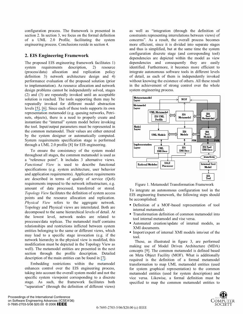
Figure 2 presents a simple application as an example. A user (student) initiates a simple search in a library OPAC, thus performs a database search through the appropriate CGI in the Web server. The example involves three modules: Web Client, Web Server and External Database Server, consisting of services. Web Server module, for example, includes two services, Get Page and Perform Search. Figure 2 illustrates also the implementation of the Simple Search service as well as a fraction of the Operation Dictionary. The dotted lines indicate the correspondences among the external part of the Functional View, the implementation of Simple Search and the Operation Dictionary fraction.
0-7695-2703-5/06/$20.00 (c) IEEE
Proceedings of the International Conferenceon Software Engineering Advances (ICSEA'06)0-7695-2703-5/06 $20.00 © 2006
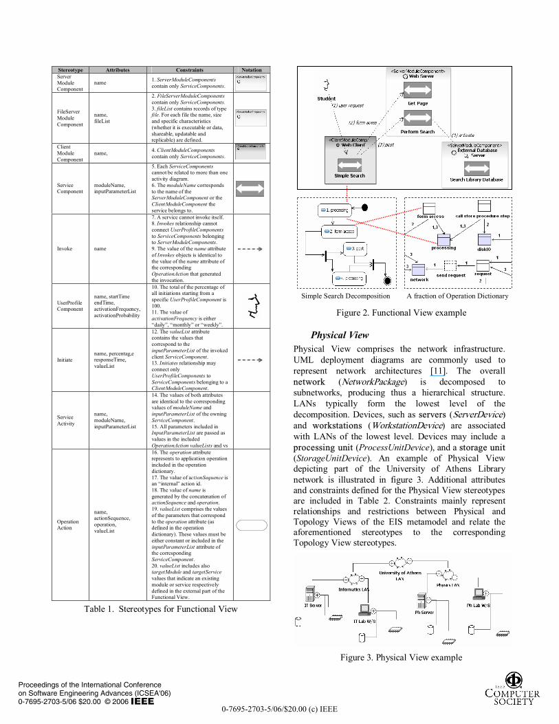
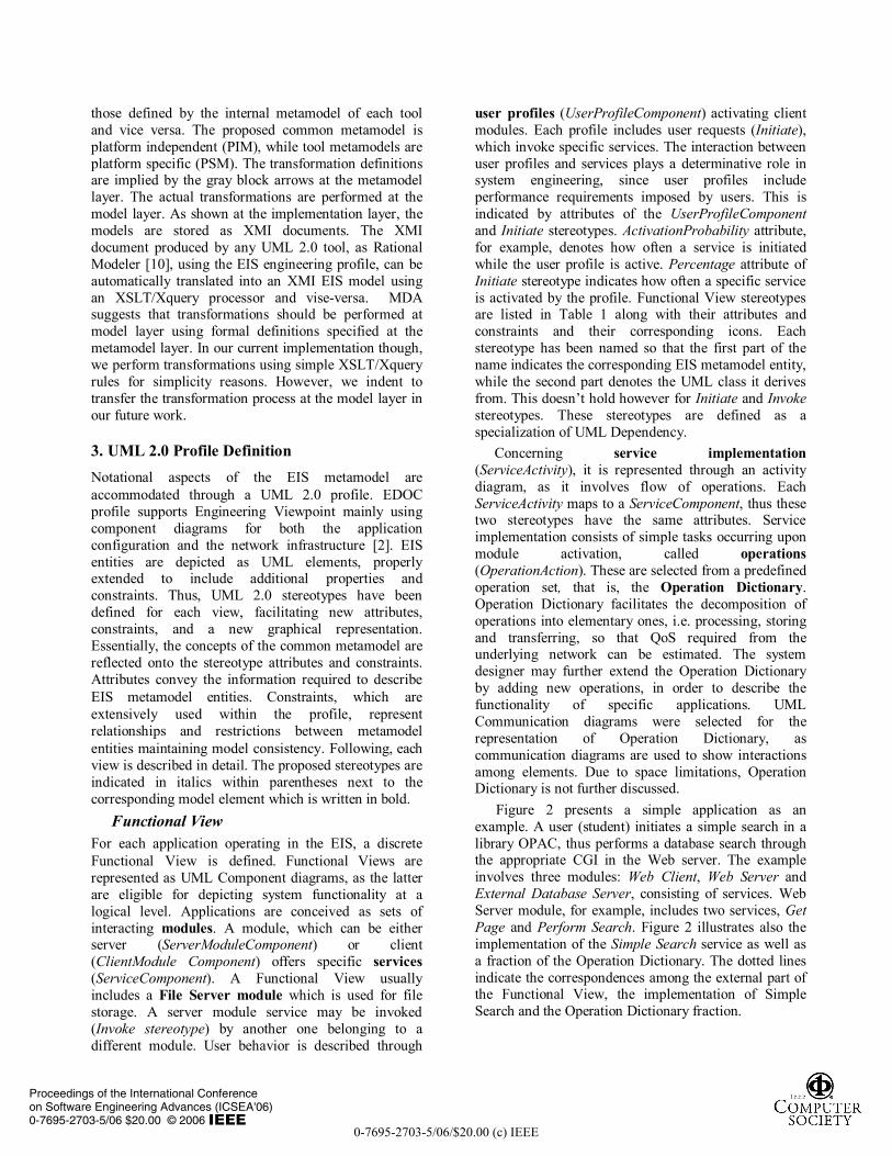
Table 1. Stereotypes for Functional View
Figure 2. Functional View example
Physical View Physical View comprises the network infrastructure. UML deployment diagrams are commonly used to represent network architectures [11]. The overall network (NetworkPackage) is decomposed to subnetworks, producing thus a hierarchical structure. LANs typically form the lowest level of the decomposition. Devices, such as servers (ServerDevice) and workstations (WorkstationDevice) are associated with LANs of the lowest level. Devices may include a processing unit (ProcessUnitDevice), and a storage unit (StorageUnitDevice). An example of Physical View depicting part of the University of Athens Library network is illustrated in figure 3. Additional attributes and constraints defined for the Physical View stereotypes are included in Table 2. Constraints mainly represent relationships and restrictions between Physical and Topology Views of the EIS metamodel and relate the aforementioned stereotypes to the corresponding Topology View stereotypes.
Figure 3. Physical View example
Stereotype Attributes Constraints Notation Server Module Component
name 1. ServerModuleComponents contain only ServiceComponents.
FileServer Module Component
name, fileList
2. FileServerModuleComponents contain only ServiceComponents. 3. fileList contains records of type file. For each file the name, size and specific characteristics (whether it is executable or data, shareable, updatable and replicable) are defined.
Client Module Component
name, 4. ClientModuleComponents contain only ServiceComponents.
Service Component
moduleName, inputParameterList
5. Each ServiceComponents cannot be related to more than one activity diagram. 6. The moduleName corresponds to the name of the ServerModuleComponent or the ClientModuleComponent the service belongs to.
Invoke name
7. A service cannot invoke itself. 8. Invokes relationship cannot connect UserProfileComponents to ServiceComponents belonging to ServerModuleComponents. 9. The value of the name attribute of Invokes objects is identical to the value of the name attribute of the corresponding OperationAction that generated the invocation.
UserProfile Component
name, startTime endTime, activationFrequency, activationProbability
10. The total of the percentage of all initiations starting from a specific UserProfileComponent is 100. 11. The value of activationFrequency is either “daily”, “monthly” or “weekly”.
Initiate name, percentag,e responseTime, valueList
12. The valueList attribute contains the values that correspond to the inputParameterList of the invoked client ServiceComponent. 13. Initiates relationship may connect only UserProfileComponents to ServiceComponents belonging to a ClientModuleComponent.
Service Activity
name, moduleName, inputParameterList
14. The values of both attributes are identical to the corresponding values of moduleName and inputParameterList of the owning ServiceComponent. 15. All parameters included in InputParameterList are passed as values in the included OperationAction valueLists and vs
Operation Action
name, actionSequence, operation, valueList
16. The operation attribute represents to application operation included in the operation dictionary. 17. The value of actionSequence is an “internal” action id. 18. The value of name is generated by the concatenation of actionSequence and operation. 19. valueList comprises the values of the parameters that correspond to the operation attribute (as defined in the operation dictionary). These values must be either constant or included in the inputParameterList attribute of the corresponding ServiceComponent. 20. valueList includes also targetModule and targetService values that indicate an existing module or service respectively defined in the external part of the Functional View.
Simple Search Decomposition A fraction of Operation Dictionary
0-7695-2703-5/06/$20.00 (c) IEEE
Proceedings of the International Conferenceon Software Engineering Advances (ICSEA'06)0-7695-2703-5/06 $20.00 © 2006
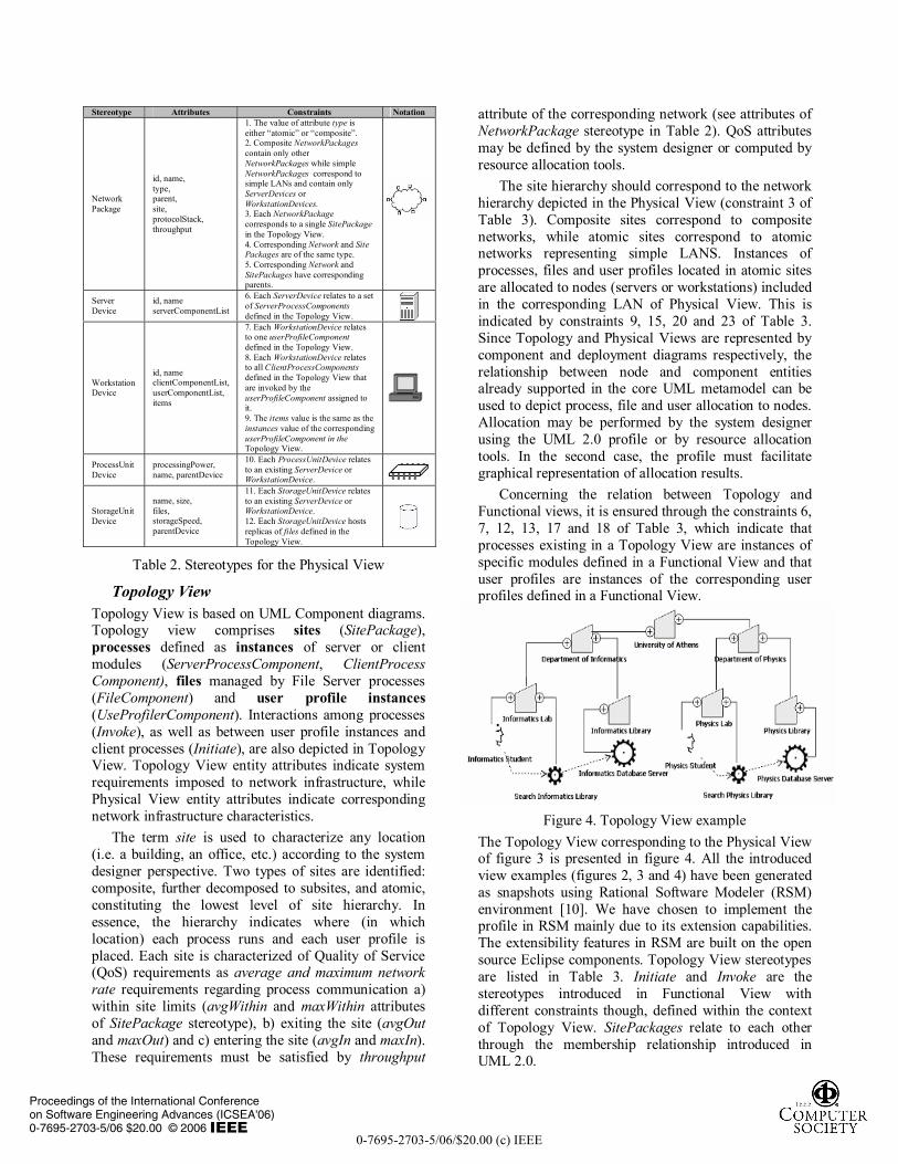
Table 2. Stereotypes for the Physical View
Topology View Topology View is based on UML Component diagrams. Topology view comprises sites (SitePackage), processes defined as instances of server or client modules (ServerProcessComponent, ClientProcess Component), files managed by File Server processes (FileComponent) and user profile instances (UseProfilerComponent). Interactions among processes (Invoke), as well as between user profile instances and client processes (Initiate), are also depicted in Topology View. Topology View entity attributes indicate system requirements imposed to network infrastructure, while Physical View entity attributes indicate corresponding network infrastructure characteristics.
The term site is used to characterize any location (i.e. a building, an office, etc.) according to the system designer perspective. Two types of sites are identified: composite, further decomposed to subsites, and atomic, constituting the lowest level of site hierarchy. In essence, the hierarchy indicates where (in which location) each process runs and each user profile is placed. Each site is characterized of Quality of Service (QoS) requirements as average and maximum network rate requirements regarding process communication a) within site limits (avgWithin and maxWithin attributes of SitePackage stereotype), b) exiting the site (avgOut and maxOut) and c) entering the site (avgIn and maxIn). These requirements must be satisfied by throughput
attribute of the corresponding network (see attributes of NetworkPackage stereotype in Table 2). QoS attributes may be defined by the system designer or computed by resource allocation tools.
The site hierarchy should correspond to the network hierarchy depicted in the Physical View (constraint 3 of Table 3). Composite sites correspond to composite networks, while atomic sites correspond to atomic networks representing simple LANS. Instances of processes, files and user profiles located in atomic sites are allocated to nodes (servers or workstations) included in the corresponding LAN of Physical View. This is indicated by constraints 9, 15, 20 and 23 of Table 3. Since Topology and Physical Views are represented by component and deployment diagrams respectively, the relationship between node and component entities already supported in the core UML metamodel can be used to depict process, file and user allocation to nodes. Allocation may be performed by the system designer using the UML 2.0 profile or by resource allocation tools. In the second case, the profile must facilitate graphical representation of allocation results.
Concerning the relation between Topology and Functional views, it is ensured through the constraints 6, 7, 12, 13, 17 and 18 of Table 3, which indicate that processes existing in a Topology View are instances of specific modules defined in a Functional View and that user profiles are instances of the corresponding user profiles defined in a Functional View.
Figure 4. Topology View example
The Topology View corresponding to the Physical View of figure 3 is presented in figure 4. All the introduced view examples (figures 2, 3 and 4) have been generated as snapshots using Rational Software Modeler (RSM) environment [10]. We have chosen to implement the profile in RSM mainly due to its extension capabilities. The extensibility features in RSM are built on the open source Eclipse components. Topology View stereotypes are listed in Table 3. Initiate and Invoke are the stereotypes introduced in Functional View with different constraints though, defined within the context of Topology View. SitePackages relate to each other through the membership relationship introduced in UML 2.0.
Stereotype Attributes Constraints Notation
Network Package
id, name, type, parent, site, protocolStack, throughput
1. The value of attribute type is either “atomic” or “composite”. 2. Composite NetworkPackages contain only other NetworkPackages while simple NetworkPackages correspond to simple LANs and contain only ServerDevices or WorkstationDevices. 3. Each NetworkPackage corresponds to a single SitePackage in the Topology View. 4. Corresponding Network and Site Packages are of the same type. 5. Corresponding Network and SitePackages have corresponding parents.
Server Device
id, name serverComponentList
6. Each ServerDevice relates to a set of ServerProcessComponents defined in the Topology View.
Workstation Device
id, name clientComponentList, userComponentList, items
7. Each WorkstationDevice relates to one userProfileComponent defined in the Topology View. 8. Each WorkstationDevice relates to all ClientProcessComponents defined in the Topology View that are invoked by the userProfileComponent assigned to it. 9. The items value is the same as the instances value of the corresponding userProfileComponent in the Topology View.
ProcessUnit Device
processingPower, name, parentDevice
10. Each ProcessUnitDevice relates to an existing ServerDevice or WorkstationDevice.
StorageUnit Device
name, size, files, storageSpeed, parentDevice
11. Each StorageUnitDevice relates to an existing ServerDevice or WorkstationDevice. 12. Each StorageUnitDevice hosts replicas of files defined in the Topology View.
0-7695-2703-5/06/$20.00 (c) IEEE
Proceedings of the International Conferenceon Software Engineering Advances (ICSEA'06)0-7695-2703-5/06 $20.00 © 2006
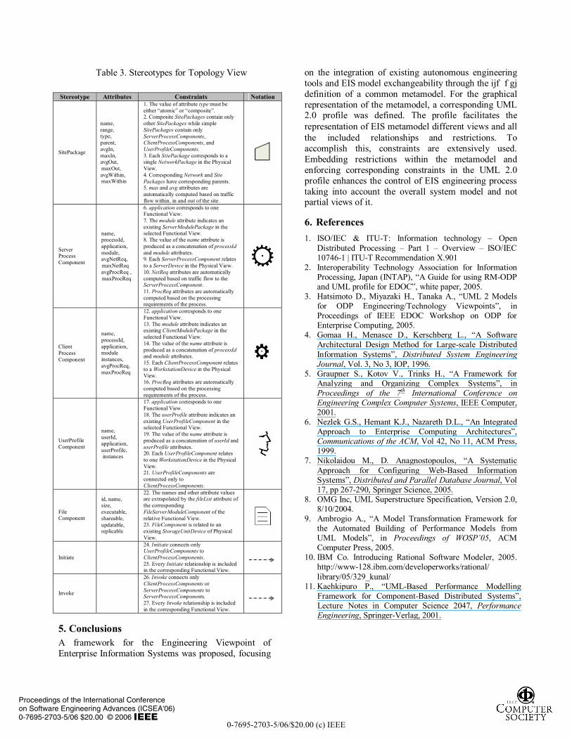
Table 3. Stereotypes for Topology View
5. Conclusions A framework for the Engineering Viewpoint of Enterprise Information Systems was proposed, focusing
on the integration of existing autonomous engineering tools and EIS model exchangeability through the ijf f gj definition of a common metamodel. For the graphical representation of the metamodel, a corresponding UML 2.0 profile was defined. The profile facilitates the representation of EIS metamodel different views and all the included relationships and restrictions. To accomplish this, constraints are extensively used. Embedding restrictions within the metamodel and enforcing corresponding constraints in the UML 2.0 profile enhances the control of EIS engineering process taking into account the overall system model and not partial views of it.
6. References 1. ISO/IEC & ITU-T: Information technology – Open
Distributed Processing – Part 1 – Overview – ISO/IEC 10746-1 | ITU-T Recommendation X.901
2. Interoperability Technology Association for Information Processing, Japan (INTAP), “A Guide for using RM-ODP and UML profile for EDOC”, white paper, 2005.
3. Hatsimoto D., Miyazaki H., Tanaka A., “UML 2 Models for ODP Engineering/Technology Viewpoints”, in Proceedings of IEEE EDOC Workshop on ODP for Enterprise Computing, 2005.
4. Gomaa H., Menasce D., Kerschberg L., “A Software Architectural Design Method for Large-scale Distributed Information Systems”, Distributed System Engineering Journal, Vol. 3, No 3, IOP, 1996.
5. Graupner S., Kotov V., Trinks H., “A Framework for Analyzing and Organizing Complex Systems”, in Proceedings of the 7th International Conference on Engineering Complex Computer Systems, IEEE Computer, 2001.
6. Nezlek G.S., Hemant K.J., Nazareth D.L., “An Integrated Approach to Enterprise Computing Architectures”, Communications of the ACM, Vol 42, No 11, ACM Press, 1999.
7. Nikolaidou M., D. Anagnostopoulos, “A Systematic Approach for Configuring Web-Based Information Systems”, Distributed and Parallel Database Journal, Vol 17, pp 267-290, Springer Science, 2005.
8. OMG Inc, UML Superstructure Specification, Version 2.0, 8/10/2004.
9. Ambrogio A., “A Model Transformation Framework for the Automated Building of Performance Models from UML Models”, in Proceedings of WOSP’05, ACM Computer Press, 2005.
10. IBM Co. Introducing Rational Software Modeler, 2005. http://www-128.ibm.com/developerworks/rational/ library/05/329_kunal/
11. Kaehkipuro P., “UML-Based Performance Modelling Framework for Component-Based Distributed Systems”, Lecture Notes in Computer Science 2047, Performance Engineering, Springer-Verlag, 2001.
Stereotype Attributes Constraints Notation
SitePackage
name, range, type, parent, avgIn, maxIn, avgOut, maxOut, avgWithin, maxWithin
1. The value of attribute type must be either “atomic” or “composite”. 2. Composite SitePackages contain only other SitePackages while simple SitePackages contain only ServerProcessComponents, ClientProcessComponents, and UserProfileComponents. 3. Each SitePackage corresponds to a single NetworkPackage in the Physical View. 4. Corresponding Network and Site Packages have corresponding parents. 5. max and avg attributes are automatically computed based on traffic flow within, in and out of the site.
Server Process Component
name, processId, application, module, avgNetReq, maxNetReq avgProcReq , maxProcReq
6. application corresponds to one Functional View. 7. The module attribute indicates an existing ServerModulePackage in the selected Functional View. 8. The value of the name attribute is produced as a concatenation of processId and module attributes. 9. Each ServerProcessComponent relates to a ServerDevice in the Physical View. 10. NetReq attributes are automatically computed based on traffic flow to the ServerProcessComponent. 11. ProcReq attributes are automatically computed based on the processing requirements of the process.
Client Process Component
name, processId, application, module instances, avgProcReq, maxProcReq
12. application corresponds to one Functional View. 13. The module attribute indicates an existing ClientModulePackage in the selected Functional View. 14. The value of the name attribute is produced as a concatenation of processId and module attributes. 15. Each ClientProcessComponent relates to a WorkstationDevice in the Physical View. 16. ProcReq attributes are automatically computed based on the processing requirements of the process.
UserProfile Component
name, userId, application, userProfile, instances
17. application corresponds to one Functional View. 18. The userProfile attribute indicates an existing UserProfileComponent in the selected Functional View. 19. The value of the name attribute is produced as a concatenation of userId and userProfile attributes. 20. Each UserProfileComponent relates to one WorkstationDevice in the Physical View. 21. UserProfileComponents are connected only to ClientProcessComponents.
File Component
id, name, size, executable, shareable, updatable, replicable
22. The names and other attribute values are extrapolated by the fileList attribute of the corresponding FileServerModuleComponent of the relative Functional View. 23. FileComponent is related to an existing StorageUnitDevice of Physical View.
Initiate
24. Initiate connects only UserProfileComponents to ClientProcessComponents. 25. Every Initiate relationship is included in the corresponding Functional View.
Invoke
26. Invoke connects only ClientProcessComponents or ServerProcessComponents to ServerProcessComponents. 27. Every Invoke relationship is included in the corresponding Functional View.
0-7695-2703-5/06/$20.00 (c) IEEE
Proceedings of the International Conferenceon Software Engineering Advances (ICSEA'06)0-7695-2703-5/06 $20.00 © 2006
Related Documents