Extending Simulink Models With Natural Relations To Improve Automated Model-Based Testing Lisa M. Boden Lockheed Martin Space Systems Company [email protected] Robert D. Busser Mark R. Blackburn Aaron M. Nauman Software Productivity Consortium/T-VEC {busser,blackburn,nauman}@software.org Abstract The Simulink Model Tester “global assertions” capability developed by the Software Productivity Consortium and T-VEC Technologies is described in this paper. This assertions mechanism incorporates design assumptions or NATural relationships with Simulink models to automatically generate more valid test vectors using the Test Automation Framework. The positive impact this mechanism has on development and testing of Simulink models for the Lockheed Martin Space System’s Independent Verification and Validation team is also discussed. 1. Introduction The Lockheed Martin Space System’s Independent Verification and Validation (IV&V) team has been applying the Software Productivity Consortium’s (SPC) Test Automation Framework (TAF) to evaluate and test flight software requirements, design, and code. TAF is a domain- based test generation process that consists of entering requirements or design information into a modeling program and automatically generating test vectors and test drivers using the T-VEC tool, for execution of unit, integration, or system-level tests directly from the model. Software modeling tools come in two varieties, requirements tools and design tools. Requirements models include all relevant relationship information about inputs, outputs, and functions. In a requirements model, functional requirements are expressed as mappings from inputs to outputs (i.e., functions) that are governed by constraint expressions. The Software Cost Reduction (SCR) tool is a requirements-based, table-driven modeling tool that is used in the TAF process. SCR and other requirements-based tools incorporate natural property input (NAT) relationships that are used to describe the constraints imposed by physical laws (“invariants”) and the system environment (“assertions”) [1]. There is no analog to NAT relationships in design models since these relationships are not required for simulation or code generation. Design models typically expect such relationships to be maintained by the input values fed into simulation runs or by the physical sensor inputs that feed the execution of auto- generated code in the target application. NAT relationships, expected by the design but not included in the model, are not available for model analysis or test generation. Such relationships are often critical to the proper operation of the design and test vectors produced, or analysis conducted, which will either be invalid or will not accurately reflect the true operation of the system. 1.1 Background The TAF approach for model-based analysis and test automation was developed by the SPC in conjunction with T-VEC Technologies [2]. TAF integrates various model development and test generation tools to support defect prevention and automated testing of systems and software. TAF supports model analysis and test generation for both requirements-based and design-based modeling tools. Model translation converts Simulink models into a form where T-VEC, the test generation component of TAF, produces test vectors. Test vectors include inputs as well as the expected outputs with requirement-to-test traceability information. T-VEC also supports test driver generation, requirement test coverage analysis, and test results checking and reporting. The test driver mappings and test vectors are inputs to the test driver generator, which produces test drivers that are then executed against the implemented system during test execution.

Welcome message from author
This document is posted to help you gain knowledge. Please leave a comment to let me know what you think about it! Share it to your friends and learn new things together.
Transcript
Extending Simulink Models With Natural Relations To Improve Automated Model-Based Testing
Lisa M. Boden Lockheed Martin Space Systems Company
Robert D. Busser Mark R. Blackburn Aaron M. Nauman
Software Productivity Consortium/T-VEC {busser,blackburn,nauman}@software.org
Abstract
The Simulink Model Tester “global assertions”
capability developed by the Software Productivity Consortium and T-VEC Technologies is described in this paper. This assertions mechanism incorporates design assumptions or NATural relationships with Simulink models to automatically generate more valid test vectors using the Test Automation Framework. The positive impact this mechanism has on development and testing of Simulink models for the Lockheed Martin Space System’s Independent Verification and Validation team is also discussed. 1. Introduction
The Lockheed Martin Space System’s Independent Verification and Validation (IV&V) team has been applying the Software Productivity Consortium’s (SPC) Test Automation Framework (TAF) to evaluate and test flight software requirements, design, and code. TAF is a domain-based test generation process that consists of entering requirements or design information into a modeling program and automatically generating test vectors and test drivers using the T-VEC tool, for execution of unit, integration, or system-level tests directly from the model.
Software modeling tools come in two varieties, requirements tools and design tools. Requirements models include all relevant relationship information about inputs, outputs, and functions. In a requirements model, functional requirements are expressed as mappings from inputs to outputs (i.e., functions) that are governed by constraint expressions. The Software Cost Reduction (SCR) tool is a requirements-based, table-driven modeling tool that is used in the TAF process. SCR and other requirements-based tools incorporate natural property input (NAT) relationships that are used to describe
the constraints imposed by physical laws (“invariants”) and the system environment (“assertions”) [1].
There is no analog to NAT relationships in design models since these relationships are not required for simulation or code generation. Design models typically expect such relationships to be maintained by the input values fed into simulation runs or by the physical sensor inputs that feed the execution of auto-generated code in the target application. NAT relationships, expected by the design but not included in the model, are not available for model analysis or test generation. Such relationships are often critical to the proper operation of the design and test vectors produced, or analysis conducted, which will either be invalid or will not accurately reflect the true operation of the system. 1.1 Background
The TAF approach for model-based analysis and test automation was developed by the SPC in conjunction with T-VEC Technologies [2]. TAF integrates various model development and test generation tools to support defect prevention and automated testing of systems and software. TAF supports model analysis and test generation for both requirements-based and design-based modeling tools.
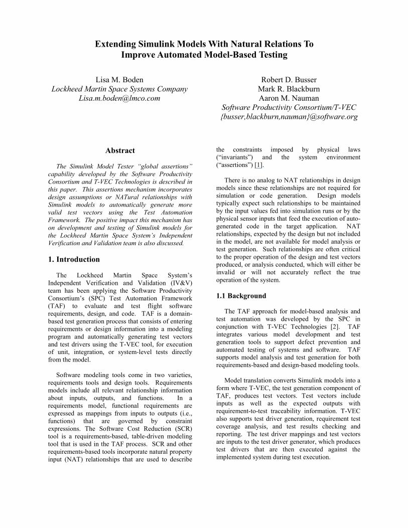
Model translation converts Simulink models into a form where T-VEC, the test generation component of TAF, produces test vectors. Test vectors include inputs as well as the expected outputs with requirement-to-test traceability information. T-VEC also supports test driver generation, requirement test coverage analysis, and test results checking and reporting. The test driver mappings and test vectors are inputs to the test driver generator, which produces test drivers that are then executed against the implemented system during test execution.
TestDrivers
TestVectors
ModelAnalysis &Coverage
Test ResultsAnalysis
Simulink/Stateflowor
MatrixXModel
T-VECSpecifications
ExecutionEnvironment
TestResults
AutocodeSource Code
Source CodeCreated by Hand
Simulink orMATRIXx
SL2TVEC orMX2TVEC T-VEC
Figure 1. Simulink Modeling Process Flow
Simulink is a design-based modeling tool created by MathWorks that uses graphical blocks to represent mathematical and logical constructs and process flow [3]. A Simulink model is a representation of the design or implementation of a system that satisfies a set of requirements. The TAF approach with design-based modeling is depicted in Figure 1 [4]. 1.2 Scope
IV&V has been applying the TAF approach with the
Simulink tool during the past year to generate models, test vectors, and test drivers for various flight software subsystems. Simulink is more advantageous than SCR in modeling mathematically intensive subsystems, but poses a fundamental limitation for model analysis and test generation since the NAT relationships are not explicitly captured in the model. Not incorporating implicit design assumptions into Simulink models may lead to inconsistencies, errors, and/or unexpected results for test vector generation and execution.
Simulink models are translated into T-VEC Standard form using the sl2tvec translator, which is part of the Simulink Model Tester utility. The Simulink Model Tester utility includes capabilities related to translation, signal ranges, test sequences, model coverage, etc. One of the newest components of the Simulink Model Tester is referred to as the “global assertions” mechanism. This mechanism supports the capture of NAT relationships that are compiled along with the model during translation and incorporated into the knowledge base used for analysis and test vector generation. The assertions mechanism ensures that proper relationships between
input signals are understood by T-VEC during the creation of test vectors. These assertions further prove model properties and/or design assumptions.
The IV&V team applied the assertions mechanism to successfully generate test vectors for models that previously received inconsistencies or errors due to ignoring important NAT relationships. The remainder of this paper provides more details about using the Simulink Model Tester utility to integrate NAT relationships with Simulink models to enable the generation of more valid, representative test vectors. The difficulties experienced by IV&V in generating test vectors using TAF without assertions, and in developing test vectors through traditional methods prior to applying TAF are included also. 2. TAF and NAT Relationships
2.1 Implicit Design Constraints
In flight systems, design assumptions or NAT
relationships are related to a mission profile and are often satisfied through the values given to the corresponding mission parameters. Some NAT relationships are due to physical or mathematical laws and properties. For example, a system with inputs that are components of geometric unit vectors must have a magnitude equal to one (sqrt(x**2 + y**2 + z**2) = 1). In a Simulink model containing unit vectors created by IV&V, the T-VEC tool did not derive meaningful input values for the unit vector components when generating test vectors. These input values impacted the validity of subsequent calculations and output values.
Another example is a system that includes trigonometric computations. IV&V defined ranges for the input signals that resulted in invalid values (e.g., -1.17) being generated as inputs into the arcsine function. Simulink performs calculations even with invalid input values. Relationships among the inputs need to be explicitly defined with the model to prevent calculations with invalid values.
A third example is a system designed for an elliptical or near-circular orbit. The eccentricity value for such a mission must be between 0 and 1, non-inclusive. Mission-specific input parameters typically enforce this design assumption. In a Simulink model created by IV&V, this design constraint was not explicitly defined. A divide-by-zero error was generated for one test vector due to the eccentricity being calculated to be 1 (i.e., parabolic orbit) and a subsequent denominator being equal to (eccentricity – 1). 2.2 Adding NAT Relationships to Models
IV&V created several Simulink models that resulted in test vector generation problems due to the design constraints not being made obvious within the model. The introduction of the assertions mechanism into the Simulink Model Tester utility alleviated this fundamental problem. For example, the following assertion was added to a Simulink model to ensure that the components of a unit vector maintain a proper relationship to each other when test vectors are generated:
unit_vector_relation(x:float; y:float; z:float) CONSTRAINT (x**2 + y**2 + z**2) = 1
This assertion was then added during the translation of the Simulink model to T-VEC Standard form as an additional constraint governing the model. Although not really a part of the model, this constraint enforced the desired relationship among the designated inputs and provided T-VEC with the information necessary to generate vectors with valid values for the input signals. 2.3 Traditional Method to Generate Test Vectors
IV&V manually developed test vectors for unit and integration testing prior to implementing the TAF approach. Input variable ranges and values were extracted from the requirements or the design, and Microsoft Excel or MathWorks’ Matlab was used to generate expected output values for math-intensive subsystems. The overall testing goal was to obtain 100% decision and statement coverage with a best attempt at exercising the limits, boundaries, and thresholds of the unit or subsystem under test. In addition, a careful
comparison was done between the requirements and the code, but sometimes only with an “eyeball” check. Although this process involved a check of both the requirements and the code, and execution of the code using an automated tool, there are obvious disadvantages. The entire process is very time consuming. It is also difficult to create a comprehensive set of test vectors to drive out domain and computation errors. Excel and Matlab are relatively easy to use, but Excel spreadsheets and Matlab scripts are often not easy to understand and edit if passed from one engineer to another for reuse or regression testing.
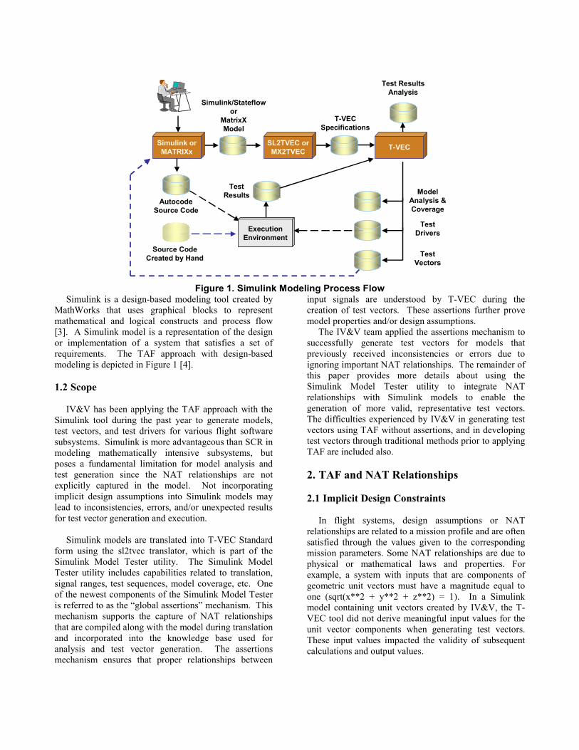
For example, Matlab scripts were created to generate test cases for the calculation of the eccentricity and semi-major axis of an orbit. Eccentricity is a measure of how near an ellipse is to being a circle (Figure 2). A circle is considered an ellipse with eccentricity equal to 0.
Increasing Eccentricity Figure 2. Eccentricity Values
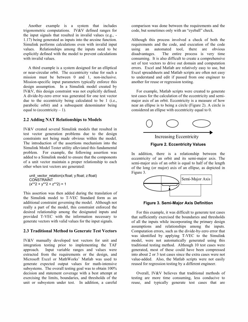
In addition, there is a relationship between the eccentricity of an orbit and its semi-major axis. The semi-major axis of an orbit is equal to half of the length of the long (or major) axis of an ellipse, as depicted in Figure 3.
Semi-Major Axis
Figure 3. Semi-Major Axis Definition
For this example, it was difficult to generate test cases
that sufficiently exercised the boundaries and thresholds of all the inputs while incorporating the primary design assumptions and relationships among the inputs. Computation errors, such as the divide-by-zero error that was identified by applying T-VEC to the Simulink model, were not automatically generated using this traditional testing method. Although 10 test cases were generated, most of these could have been compressed into about 2 or 3 test cases since the extra cases were not value-added. Also, the Matlab scripts were not easily reused for regression testing by a different engineer.
Overall, IV&V believes that traditional methods of testing are more time consuming, less conducive to reuse, and typically generate test cases that are
redundant, lower quality, and less likely to drive out domain and computation errors than the TAF approach. 2.4 Using TAF to Generate Test Vectors
IV&V has applied TAF with both the SCR and
Simulink modeling tools to about five different flight subsystems over the past four years. It takes time to learn and apply the TAF process, but it provides significant improvements over manual testing in terms of overall testing completeness, effectiveness, and efficiency. Modeling with SCR or Simulink forces a detailed examination and understanding of the requirements and design. Contradictions, coverage errors, and computational errors found by T-VEC during test vector generation allow the discovery of requirements and/or design errors even before test execution.
Another advantage in applying TAF with Simulink is that the models are easy to understand, debug, and reuse. IV&V has created a library of smaller, reusable models that are applicable to more than one flight software system. These models can be used for regression testing on the same system or reused on a different system. It is expected that a large amount of time will be saved even after a one-time reuse of these models.
3. Defining NAT Relationships From IV&V’s perspective, the main limitation in the
TAF process has been vastly improved by the inclusion of the assertions mechanism in the Simulink Model Tester. This mechanism minimizes the inconsistencies and errors that are more often generated when the implicit design assumptions and relationships are not understood by T-VEC when generating test vectors. The assertion mechanism brings more validity and completeness to the test vectors and makes the entire TAF process more efficient by minimizing the need to perform manual manipulation and analysis.
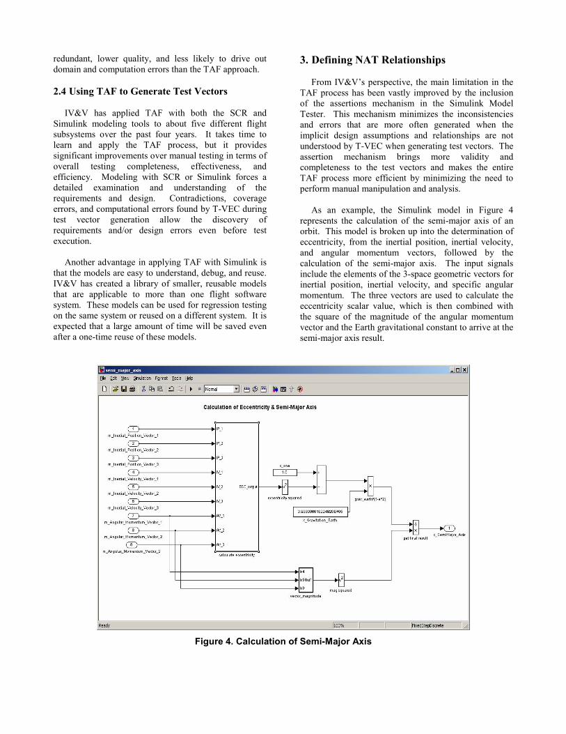
As an example, the Simulink model in Figure 4 represents the calculation of the semi-major axis of an orbit. This model is broken up into the determination of eccentricity, from the inertial position, inertial velocity, and angular momentum vectors, followed by the calculation of the semi-major axis. The input signals include the elements of the 3-space geometric vectors for inertial position, inertial velocity, and specific angular momentum. The three vectors are used to calculate the eccentricity scalar value, which is then combined with the square of the magnitude of the angular momentum vector and the Earth gravitational constant to arrive at the semi-major axis result.
Figure 4. Calculation of Semi-Major Axis
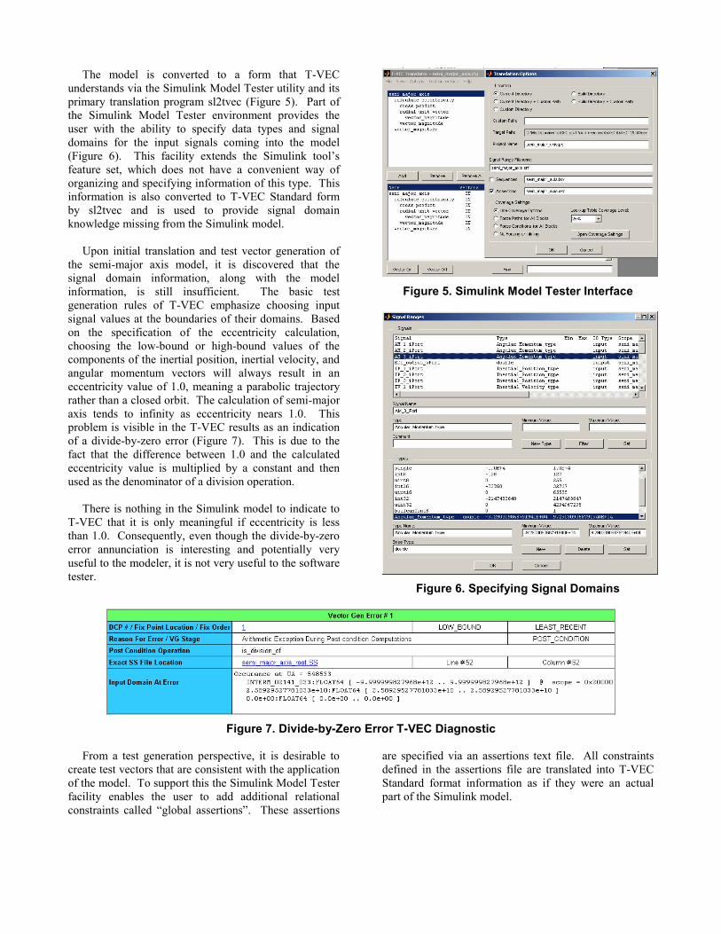
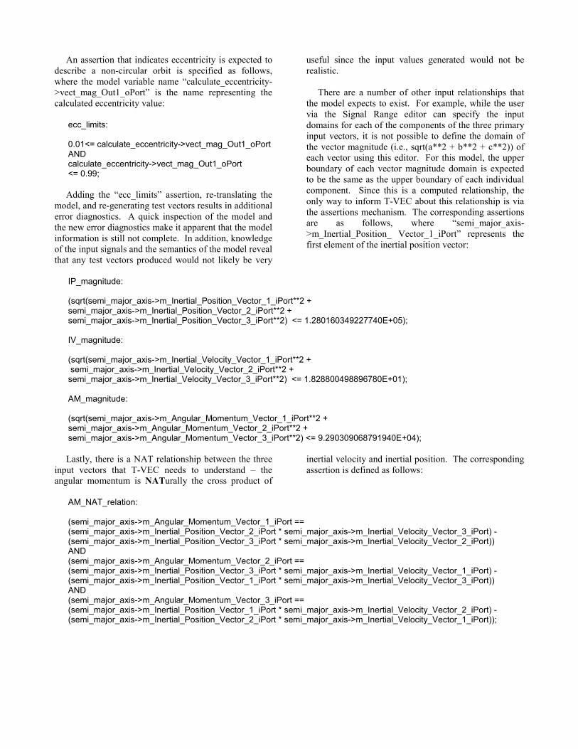
The model is converted to a form that T-VEC understands via the Simulink Model Tester utility and its primary translation program sl2tvec (Figure 5). Part of the Simulink Model Tester environment provides the user with the ability to specify data types and signal domains for the input signals coming into the model (Figure 6). This facility extends the Simulink tool’s feature set, which does not have a convenient way of organizing and specifying information of this type. This information is also converted to T-VEC Standard form by sl2tvec and is used to provide signal domain knowledge missing from the Simulink model.
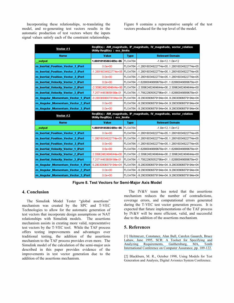
Upon initial translation and test vector generation of the semi-major axis model, it is discovered that the signal domain information, along with the model information, is still insufficient. The basic test generation rules of T-VEC emphasize choosing input signal values at the boundaries of their domains. Based on the specification of the eccentricity calculation, choosing the low-bound or high-bound values of the components of the inertial position, inertial velocity, and angular momentum vectors will always result in an eccentricity value of 1.0, meaning a parabolic trajectory rather than a closed orbit. The calculation of semi-major axis tends to infinity as eccentricity nears 1.0. This problem is visible in the T-VEC results as an indication of a divide-by-zero error (Figure 7). This is due to the fact that the difference between 1.0 and the calculated eccentricity value is multiplied by a constant and then used as the denominator of a division operation.
There is nothing in the Simulink model to indicate to T-VEC that it is only meaningful if eccentricity is less than 1.0. Consequently, even though the divide-by-zero error annunciation is interesting and potentially very useful to the modeler, it is not very useful to the software tester.
Figure 5. Simulink Model Tester Interface
Figure 6. Specifying Signal Domains
Figure 7. Divide-by-Zero Error T-VEC Diagnostic
From a test generation perspective, it is desirable to
create test vectors that are consistent with the application of the model. To support this the Simulink Model Tester facility enables the user to add additional relational constraints called “global assertions”. These assertions
are specified via an assertions text file. All constraints defined in the assertions file are translated into T-VEC Standard format information as if they were an actual part of the Simulink model.
An assertion that indicates eccentricity is expected to describe a non-circular orbit is specified as follows, where the model variable name “calculate_eccentricity->vect_mag_Out1_oPort” is the name representing the calculated eccentricity value:
ecc_limits: 0.01<= calculate_eccentricity->vect_mag_Out1_oPort AND calculate_eccentricity->vect_mag_Out1_oPort <= 0.99;
Adding the “ecc_limits” assertion, re-translating the
model, and re-generating test vectors results in additional error diagnostics. A quick inspection of the model and the new error diagnostics make it apparent that the model information is still not complete. In addition, knowledge of the input signals and the semantics of the model reveal that any test vectors produced would not likely be very
useful since the input values generated would not be realistic.
There are a number of other input relationships that the model expects to exist. For example, while the user via the Signal Range editor can specify the input domains for each of the components of the three primary input vectors, it is not possible to define the domain of the vector magnitude (i.e., sqrt(a**2 + b**2 + c**2)) of each vector using this editor. For this model, the upper boundary of each vector magnitude domain is expected to be the same as the upper boundary of each individual component. Since this is a computed relationship, the only way to inform T-VEC about this relationship is via the assertions mechanism. The corresponding assertions are as follows, where “semi_major_axis->m_Inertial_Position_ Vector_1_iPort” represents the first element of the inertial position vector:
IP_magnitude: (sqrt(semi_major_axis->m_Inertial_Position_Vector_1_iPort**2 + semi_major_axis->m_Inertial_Position_Vector_2_iPort**2 + semi_major_axis->m_Inertial_Position_Vector_3_iPort**2) <= 1.280160349227740E+05); IV_magnitude: (sqrt(semi_major_axis->m_Inertial_Velocity_Vector_1_iPort**2 + semi_major_axis->m_Inertial_Velocity_Vector_2_iPort**2 + semi_major_axis->m_Inertial_Velocity_Vector_3_iPort**2) <= 1.828800498896780E+01); AM_magnitude: (sqrt(semi_major_axis->m_Angular_Momentum_Vector_1_iPort**2 + semi_major_axis->m_Angular_Momentum_Vector_2_iPort**2 + semi_major_axis->m_Angular_Momentum_Vector_3_iPort**2) <= 9.290309068791940E+04);
Lastly, there is a NAT relationship between the three
input vectors that T-VEC needs to understand – the angular momentum is NATurally the cross product of
inertial velocity and inertial position. The corresponding assertion is defined as follows:
AM_NAT_relation: (semi_major_axis->m_Angular_Momentum_Vector_1_iPort == (semi_major_axis->m_Inertial_Position_Vector_2_iPort * semi_major_axis->m_Inertial_Velocity_Vector_3_iPort) - (semi_major_axis->m_Inertial_Position_Vector_3_iPort * semi_major_axis->m_Inertial_Velocity_Vector_2_iPort)) AND (semi_major_axis->m_Angular_Momentum_Vector_2_iPort == (semi_major_axis->m_Inertial_Position_Vector_3_iPort * semi_major_axis->m_Inertial_Velocity_Vector_1_iPort) - (semi_major_axis->m_Inertial_Position_Vector_1_iPort * semi_major_axis->m_Inertial_Velocity_Vector_3_iPort)) AND (semi_major_axis->m_Angular_Momentum_Vector_3_iPort == (semi_major_axis->m_Inertial_Position_Vector_1_iPort * semi_major_axis->m_Inertial_Velocity_Vector_2_iPort) - (semi_major_axis->m_Inertial_Position_Vector_2_iPort * semi_major_axis->m_Inertial_Velocity_Vector_1_iPort));
Incorporating these relationships, re-translating the model, and re-generating test vectors results in the automatic production of test vectors where the inputs signal values satisfy each of the constraint relationships.
Figure 8 contains a representative sample of the test vectors produced for the top level of the model.
Figure 8. Test Vectors for Semi-Major Axis Model
4. Conclusion
The Simulink Model Tester “global assertions”
mechanism was created by the SPC and T-VEC Technologies to allow for the automatic generation of test vectors that incorporate design assumptions or NAT relationships with Simulink models. The assertions mechanism assists in creating more valid, representative test vectors by the T-VEC tool. While the TAF process offers testing improvements and advantages over traditional testing, the addition of the assertions mechanism to the TAF process provides even more. The Simulink model of the calculation of the semi-major axis described in this paper provides evidence of the improvements in test vector generation due to the addition of the assertions mechanism.
The IV&V team has noted that the assertions mechanism reduces the number of contradictions, coverage errors, and computational errors generated during the T-VEC test vector generation process. It is expected that future implementations of the TAF process by IV&V will be more efficient, valid, and successful due to the addition of the assertions mechanism. 5. References
[1] Heitmeyer, Constance, Alan Bull, Carolyn Gasarch, Bruce Labaw, June 1995, SCR: A Toolset for Specifying and Analyzing Requirements, Gaithersburg, MA, Tenth International Conference on Computer Assurance, pp. 109-122. [2] Blackburn, M. R., October 1998, Using Models for Test Generation and Analysis, Digital Avionics System Conference.

[3] The MathWorks, “Using Simulink”, 2004, http://www.mathworks.com/access/helpdesk/help/toolbox/simulink/http://www.mathworks.com/access/helpdesk/help/toolbox/simulink/. [4] Blackburn, Mark, Robert Busser, Aaron Nauman, Travis Morgan, July 2004, Test Sequences Generation from Control System Models, The 8th World Multiconference on Systemics, Cybernetics and Informatics.
Related Documents