•

Welcome message from author
This document is posted to help you gain knowledge. Please leave a comment to let me know what you think about it! Share it to your friends and learn new things together.
Transcript

Loughborough UniversityInstitutional Repository
Extending product lifecyclemanagement for
manufacturing knowledgesharing
This item was submitted to Loughborough University's Institutional Repositoryby the/an author.
Citation: CHUNGOORA, N. ... et al, 2012. Extending product lifecycle man-agement for manufacturing knowledge sharing. Proceedings of the Institution ofMechanical Engineers Part B - Journal of Enginering Manufacture, 226 (A12),pp. 2047-2063.
Additional Information:
• This article was published in the Proceedings of the Institu-tion of Mechanical Engineers Part B - Journal of EngineringManufacture [ c© Sage] and the de�nitive version is available at:http://dx.doi.org/10.1177/0954405412461741
Metadata Record: https://dspace.lboro.ac.uk/2134/11487
Version: Accepted for publication
Publisher: Sage ( c© IMechE)
Please cite the published version.
This item was submitted to Loughborough’s Institutional Repository (https://dspace.lboro.ac.uk/) by the author and is made available under the
following Creative Commons Licence conditions.
For the full text of this licence, please go to: http://creativecommons.org/licenses/by-nc-nd/2.5/

Extending Product Lifecycle Management for
manufacturing knowledge sharing
Nitishal Chungoora1*, George A Gunendran2, Robert I M Young1, Zahid Usman1, Najam A
Anjum1, Claire Palmer1, Jenny A Harding1, Keith Case1, Anne-Françoise Cutting-Decelle3
1Wolfson School of Mechanical and Manufacturing Engineering, Loughborough University,
Loughborough, UK
2Control Techniques Limited, Newtown, UK
3CODATA France, Paris, France; Université Lille Nord de France, Lille, France; LM2O,
Ecole Centrale de Lille, Villeneuve d’Ascq, France
*Corresponding author:
Dr N. Chungoora
Wolfson School of Mechanical and Manufacturing Engineering, Loughborough University,
Loughborough, Leicestershire, LE11 3TU, UK
Email: [email protected]

Abstract
Product Lifecycle Management (PLM) provides a framework for information sharing which
promotes various types of decision making procedures. For PLM to advance towards
knowledge-driven decision support, then this demands more than simply exchanging
information. There is, therefore, a need to formally capture best practice through-life
engineering knowledge which can be fed back across the product lifecycle. This paper
investigates the Interoperable Manufacturing Knowledge Systems (IMKS) concept. IMKS
uses an expressive ontological approach which drives the improved configuration of PLM
systems for manufacturing knowledge sharing. An ontology of relevant core product lifecycle
concepts is identified from which viewpoint-specific domains, such as design and
manufacture, can be formalised. Essential ontology-based mechanisms are accommodated to
support the verification and sharing of manufacturing knowledge across domains. The work
has been experimentally assessed using an aerospace compressor disc design and
manufacture example. Whilst it has been demonstrated that the approach supports the
representation of disparate design and manufacture perspectives as well as manufacturing
knowledge feedback in a timely manner, areas for improvement have also been identified for
future work.
Keywords
Product Lifecycle Management, ontologies, interoperable systems, knowledge sharing,
design and manufacture

1. Introduction
As engineering enterprises seek to expand their product portfolios into the global arena, a
multitude of information is generated at various stages of the product lifecycle. The
resourceful use of this information helps organisations stay competitive within the changing
marketplace by supporting knowledge-driven decision making. The latter is reliant on the
effectiveness with which knowledge sharing across business functions is managed. For
example, appropriately-captured knowledge originating from the design, production and
service of previous product versions can be reused and tailored to meet the future planning
requirements in new product development.
Manufacturing companies are nowadays deploying a range of software solutions to improve
the visibility of information and support interactions within and across groups. The
implementation of Product Lifecycle Management (PLM) software represents one such
initiative. However, because PLM toolkits lack the adequate support for reasoning about
information structures and how to efficiently reuse these structures to enable decision
making, this implies that PLM accounts for a relatively narrow success in offering some
breadth of information support [1]. Hence, knowledge which should in fact be cross-
functional remains latent and in tacit form within its individual design and production groups.
Consequently, the interoperability of valuable knowledge across design and manufacturing
stages cannot be readily achieved using PLM toolkits alone. In the context of this work, the
term interoperability refers to the ability to promptly and accurately share computer-
interpretable knowledge across multiple application systems. This lack of interoperability
across design and manufacture implies that cross-functional communication very often

remains largely reactive and the achievement of timely exchanges continues to be a difficult
task.
Ontologies are machine-interpretable models of shared domains of interest and constitute a
subset of the underlying technologies for information and knowledge support [2]. They also
provide a basis for sharing meaning in computational form [3]. For these primary reasons,
ontologies possess attractive properties as far as knowledge capture and sharing are
concerned in PLM. Various contributions have demonstrated that the semantic value of the
captured knowledge is dependent on the expressiveness of the ontology language used [4, 5,
6]. In production engineering, heavyweight (i.e., expressive) ontologies are favoured [3, 6, 7]
as they are accompanied with logic-based reasoning mechanisms which carefully prescribe
the semantics, behaviour and conditions present within information structures. Expressive
ontologies thus impart the ability to configure knowledge models for improved decision
making [7].
This paper investigates the Interoperable Manufacturing Knowledge Systems (IMKS)
approach. The latter exploits the capabilities of expressive ontologies to configure PLM
systems, in order to offer groundbreaking potential in manufacturing knowledge support and
sharing. Moreover, the investigation has been scoped around an aerospace compressor disc
design and manufacturing perspectives. A part family and feature-based understanding has
been utilised to enable the feedback, into design realisation, of key manufacturability rules
that have a direct implication on the design of the product. This is analogous to the
coordination and sharing of critical information as key characteristics that carry crucial
product semantics throughout the product lifecycle [8].

The paper is structured as follows: Section 2 provides an overview of the IMKS approach and
analyses related work. Section 3 then explores the various facets of exploiting expressive
ontologies to capture, specialise and verify knowledge. This leads to a demonstration of the
IMKS approach in section 4 followed by relevant discussions and conclusions in sections 5
and 6 respectively.
2. Towards knowledge-driven decision making in PLM
This section presents an overview of the traditional approaches that have been utilised to
support information sharing in PLM. The IMKS approach and its contributions are then
highlighted, followed by a review of more recent and related methods, that include the
combination of PLM and knowledge-based techniques.
2.1. Traditional approaches to information sharing in PLM
The process of information sharing has traditionally been based on the exploitation of a
common schema, or product master model [9] that enforces a rigid structure to meet the
integrated information modelling needs in design and manufacture. This method of ensuring
information sharing can be problematic in a number of ways since, e.g., multiple information
viewpoints are required by design and manufacturing engineers [10, 11]. Furthermore,
engineers generally tend to have their own preferred terms that are confined to their specific
problem domains and as such, alternative representations and definitions of concepts are
inevitable [6].
Traditional approaches to information sharing in PLM have been largely driven by software
systems that focus on integration, as they support a common platform for the management of
product-related information with mechanisms to capture the essential workflows required to
achieve collaborative design and manufacture [40, 41]. An example of this has been realised
in the development of a STEP and XML-enabled PLM platform capable of integrating
several customised design tools, such as CAD and CAE instruments that have been
developed in-house [48]. The platform supports the management of flows of information that
are critical to the design process of turbomachinery.
In line with this, the evolution of PLM systems has also witnessed a shift from the utilisation
of data models to information models as methods of designing and implementing these
systems. This has been realised in line with the need to move from simply geometry-based
product information towards more meaningful feature interactions required for describing the
multiple viewpoints of the features of a product in relationship to the type of part being
modelled [10, 11, 32].
Furthermore, it is understood that the utilisation of information models for developing PLM
systems, although suitable from an integration perspective, falls short of the ability to foster
interoperability [42, 43]. Hence, there is a number of extensions required by PLM systems
and the following research questions, pertinent to the context of this article, intend to address
the related extensions:
1. What consists a suitable approach to progress towards meeting the interoperability
requirements of self-describing PLM applications?

2. To what extent is it possible to capture and reuse formalised knowledge, as opposed to
simply data and information, in the product lifecycle to help make useful and timely
decisions for benefiting product development?
3. To what extent can a progression towards rigorous semantic-based approaches support
the requirements for meeting product, process and resource lifecycle management [44]?
2.2. Overview of the IMKS approach
The Interoperable Manufacturing Knowledge Systems (IMKS) approach [12] has been
proposed as an effort towards tackling the research questions identified in section 2.1. The
approach explores radically new methods by extending PLM into a richer knowledge sharing
base to support the capture, sharing and verification of multiple sources of manufacturing
knowledge in a dynamic environment. Figure 1 identifies a high-level view of the IMKS
approach, which is further developed in section 3 of this article.
Figure 1. The Interoperable Manufacturing Knowledge Systems (IMKS) approach

Based on Figure 1, there are three main contributions that this work targets notably: (1) the
exploitation of a core ontology and specialisation mechanisms to address the interoperability
requirements of various viewpoints across the PLM, (2) the ability to capture formalised
semantics and knowledge using mathematically-rigorous and explicitly encoded, i.e.
heavyweight, ontologies, and (3) the verification and feedback of knowledge from
manufacturing stages to product design stages using ontology-based mechanisms.
2.3. Lightweight v/s heavyweight approaches
The representation of knowledge in computational form is largely dependent on the level of
rigour with which the semantics (i.e., meaning) that describe the knowledge can be modelled.
There are two types of ontology approaches that can be followed in order to model semantics.
They are notably referred to as ‘lightweight’ and ‘heavyweight’ methods. Lightweight
ontologies, e.g. data and information models, consist of simple representations that involve
taxonomies of concepts and relations and assume that the meaning associated with concept
terms is fully understood, agreed and, therefore, readily interpretable [4]. On the other hand,
heavyweight ontologies, i.e. knowledge-based models, consist of both lightweight structures
as well as formal axioms that support the definition of the semantics of terms used for
computer-based knowledge representation [4, 6]. Therefore, heavyweight (i.e., expressive)
ontologies are preferred for ensuring greater confidence behind the meaning of formalised
knowledge.
2.4. Ontologies of core concepts
Prior work [6, 7, 15] has demonstrated that an ontology of well-defined core concepts can
serve as a foundation for the sufficiently flexible development of domain-specific concepts,
such as those pertinent to feature-based design and manufacturing planning viewpoints. Thus,
the IMKS approach allows the derivation of specialised knowledge bases as repositories for
designers and planners alike, without the need to commit to a fixed master model. In that
sense, the heavyweight ontology dimension of this work builds on top of the current
perceived advantages of applying formal ontologies within a PLM context to aid the process
of semantic interoperability and knowledge exchanges [3, 6, 7, 16, 17].
There is a vital benefit to the development of specialised concept definitions from a core set
of concepts, in order to suit different stages of the product lifecycle without enforcing a single
structure. A common semantic foundation provides a means of verifying across knowledge
bases since meaningful mappings and concept lineages can be identified across the design
and production perspectives [18]. This basis constitutes another crucial facet of the IMKS
approach in being able to support manufacturing knowledge sharing mechanisms into design
realisation.
2.5. Combined PLM and knowledge-based approaches
The exploration of ontology-driven PLM systems is a relatively recent research area [17] but
is quickly gaining consideration both at research and industry level. Earlier work [5, 19, 20]
has shown that the shift towards ontology-based approaches can start to support the capture
of semantics of product data and various types of product features. A wider appreciation of

PLM coupled with knowledge-based approaches appears in more recent efforts. Raza et al.
[21] have applied ontologies within the PLM system at Ford in order to enable the
reconfiguration of assembly line to meet changing requirements, where product and resource
data in Teamcenter [22] have been translated into the Web Ontology Language (OWL) [23].
It is to be noted that most current related work in ontology-driven PLM systems [24-26]
employ OWL as ontology language.
This, therefore, raises an important concern from the point of view of semantic knowledge
capture and sharing. It has been shown that OWL is limited in representing complex
manufacturing constraints and process semantics [3, 6]. Furthermore, although some efforts
have utilised OWL with rule languages [20, 27], these rule languages do not benefit from full
first order logic constructs. They, therefore, fall short of the required expressive power and
reasoning mechanisms to accurately encode and infer over PLM subject matter.
From the perspective of developing core ontologies which then specialise into different
viewpoints across the product lifecycle, important understandings have been proposed. The
contribution by Kesavadas et al. [28] acknowledges the use of formal ontologies to
progressively capture design and manufacturing concepts. Other authors [17, 29, 30] have
identified the potentials of using upper level and core ontologies from which to relate PLM
structures. Unfortunately, these approaches either still lack the level of semantic rigour or
need to be further explored in order to be industrially viable.
Zhan et al. [26] have investigated ontologies to share knowledge regarding product data in
Computer Aided Design (CAD). Ontology mapping mechanisms have also been specified as
a means of knowledge verification across systems. On the other hand, Lee and Suh [31] have

explored a multi-layered approach to PLM using ontologies. Each layer encompasses a
specific product viewpoint in PLM and each exploits axioms, knowledge maps and
specialised domain knowledge. The latter approach, which uses the Prolog language, reflects
one of the infrequent cases in which first order logic models have been created for PLM.
An important observation regarding similar work is that while the intention to progress
towards interoperable decision making systems is present, little attempt has been made at
exploiting truly rigorous semantic definitions. Furthermore, a significant proportion of efforts
have concentrated on the representation of product design information and the capture of
design intent, thereby leaving a gap in knowledge verification from manufacturing-intensive
functions into design stages.
3. Formal ontologies to capture design and manufacturing knowledge
3.1. Building blocks of the IMKS approach
Figure 2 identifies the vital building blocks of the IMKS approach, both from a functional
and an implementation perspective. The ontology development methodology provides a route
from domain modelling to knowledge sharing by firstly including the definition of
lightweight ontology models of the necessary core concepts, design and manufacturing
domains (Figure 2A). The mechanisms for specialising the design and manufacturing
domains also need to be elicited (Figure 2B). The lightweight ontology entities, together with
the necessary semantic constraints (Figure 2C), are transformed and captured in heavyweight
format, resulting in explicitly-encoded ontologies (Figure 2D).

Figure 2. Building blocks of the IMKS approach
Another important building block is associated with the understanding and formal
specification of the mappings that hold across the specialised design and manufacture
concepts (Figure 2E). With this in place, it then becomes possible to define knowledge
verification constraints (Figure 2F) which interact with the design and manufacture concepts
to provide a basis for the interpretation and sharing of product lifecycle knowledge (Figure
2G).
From an implementation perspective, IMKS utilises ontologies, mappings and knowledge
verification constraints that are encoded in the Knowledge Frame Language (KFL) [13]. The
latter is a heavyweight ontology language based on the Common Logic standard [14] and
possesses superior expressiveness and provision for deductive reasoning mechanisms when
compared to Web Ontology Language (OWL) based technologies [6]. The defined
ontologies, present at the knowledge architecture level, are deployed using the Highfleet
Integrated Ontology Development Environment (IODE) [37] (Figure 2H).
A PLM platform, that uses Siemens Teamcenter [22] and NX CAD [38] applications, is
configured from the ontologies implemented in IODE (Figure 2I). In addition to this, new
Graphical User Interfaces (GUIs) have to be designed for use in the NX environment so as to
communicate shared knowledge at a user level. The interpretation and sharing of knowledge
is assisted by the GUIs and a Java Application Programming Interface (API) to enable
interactions between the PLM and knowledge-based platforms (Figure 2J).
3.2. Lightweight model of the Manufacturing Core Ontology
Figure 3 introduces the Manufacturing Core Ontology (i.e., ontology of core concepts), which
is first captured as a UML class model. The diagram identifies general categories of
information, the core types of concepts (i.e., classes) that fall within these categories and
important associations (i.e., relations) across concepts. The fundamentals of this ontology
involve the notion of part planning using part families and features [32, 33], where sufficient
flexibility in the formal meaning of concepts has been accommodated to support the
improved configuration of design and manufacturing solution.

Figure 3. UML class model of the Manufacturing Core Ontology
The Manufacturing Core Ontology model aims at providing an improved way for configuring
design and manufacturing computer-based systems with a focus on interoperability. This is
because various core concepts central to the description of both design and manufacturing
stages of the product lifecycle have been captured and linked. Furthermore, the relationships
specified in the model constitute the primary associations across the categories of information
and provide fundamental semantic structures for capturing meaning. An example in which
the Manufacturing Core Ontology could be exploited is in the configuration of a CAD
environment that is built upon the rationale of part families and features in design and
manufacture.
Following this example, a design solution that has been generated using the ontology-
configured CAD environment would be an instance of some specific type (i.e., subclass) of

DesignPartFamily. At a model representation level used in the configured CAD environment,
any type of DesignPartFamily holds DesignFeature types. Specific constraints and rules,
established over types of part families and types of features, dictate how a design solution is
instantiated. In other words, when some type of DesignPartFamily is instantiated into a
design solution, the latter would hold all the conditions and knowledge previously captured at
the type (i.e., class) level. The knowledge specialisation mechanisms, explored in this work,
are further discussed in section 3.3.1.
Likewise, the interactions between knowledge coming from the specialisation of
ManufacturingMethod, ManufacturingResource and ManufacturingFacility enable the useful
configuration of manufacturing solutions, i.e., instances of some type of
ManufacturingPartFamily. On the other hand, the Manufacturing Core Ontology supports the
capture of more dynamic knowledge, pertinent to shop-floor processes within the
RealisedPart domain. Altogether, the ontology presented here comprehensively models a
backbone of core concepts that reflects important stages of the product lifecycle. This has
been made possible thanks to a number of strands of work, including our long standing
contributions towards the best practice organisation and sharing of manufacturing knowledge
and substantial efforts coming from international standards [14, 34-36].
3.3. Heavyweight model of the Manufacturing Core Ontology
3.3.1. Declaration of contexts, classes and relations
The UML class model of the Manufacturing Core Ontology provides a roadmap of the
necessary ontological entities that need to be formalised in KFL, in order to obtain a
semantically rich ontology. KFL, as a knowledge representation language, possesses a
rigorously-defined meta-model which is instantiated into user-specific ontologies such as the
Manufacturing Core Ontology presented in this section. A user-specific ontology typically
occupies a context (i.e. an identifier) which references all the classes, relations, and integrity
constraints that make up the ontology.
The basic structures of the Manufacturing Core Ontology consist of the declaration of a
context, classes and relations. The core ontology occupies a context which is declared in KFL
as thus:
:Ctx MLO
:Inst UserContext
:supCtx TopUserContext
:name "Middle Level Ontology"
The directive :Ctx captures the identifier for the context, in this case MLO, which is made an
instance of UserContext and a sub-context of TopUserContext. A name can be assigned to
MLO through the :name directive. Note that the Manufacturing Core Ontology is being
developed as a middle level ontology. This is because the ontology builds its entities on top
of the system-defined context of the KFL meta-model. By using similar KFL directives, it is
possible to capture taxonomies of classes and specify relations that hold across the
individuals of these classes as prescribed in the UML class model of the ontology. These
structures are essentially instantiated from the KFL meta-model [6, 7, 15].
3.3.2. Semantic constraints
The declaration of semantic constraints is one of the fundamental strengths of heavyweight
ontologies [6, 7, 15]. Since the Manufacturing Core Ontology comprises a set of well-defined
core concepts, this implies that semantic constraints are required to catch the formal meaning
of core concepts so that the integrity-driven specialisation of viewpoint-specific knowledge
models can be ensured.
Semantic constraints can be captured by exploiting integrity constraints, which are logic-
based axioms that help confine the formal interpretation of concepts in KFL ontologies. An
example of an integrity constraint developed for the Manufacturing Core Ontology is
depicted next.
(=> (or (DesignFeature ?df)
(supTC ?df DesignFeature))
(or (not (exists (?fmm)
(and (FeatureManufacturingMethod ?fmm)
(hasManufacturingMethod ?df ?fmm))))
(not (exists (?fmm)
(and (supTC ?fmm FeatureManufacturingMethod)
(hasManufacturingMethodType ?df ?fmm))))))
:IC hard "A DesignFeature type/individual cannot have an
associated FeatureManufacturingMethod type/individual, since
the latter is only applicable to ManufacturingFeature
types/individuals."
The integrity constraint expression is intended to make core concepts foolproof when they are
specialised. The axiom is stating that given a DesignFeature individual or subtype of
DesignFeature, then it is not possible for these entities to be related to some individual or
subtype of FeatureManufacturingMethod. This is because the latter is reserved exclusively
for reasoning about individuals and subtypes of ManufacturingFeature [15]. Notice how the
expression is appended with an :IC hard directive followed by the natural language
interpretation of the integrity constraint. A hard integrity constraint, i.e., :IC hard, ensures
that rigorous semantics are stored through compulsory conditions. This level of granularity of
constraint on knowledge is currently not achievable in OWL-based approaches, hence the
benefit of using a KFL approach over mainstream ontology languages to capture more
expressive semantics.
3.4. Specialisation of knowledge models, mappings and verification
3.4.1. Specialisation mechanisms
In this section, a very simple part family and feature understanding is applied to illustrate
specialisation mechanisms and those utilised for verifying cross-functional knowledge.
Figure 4 identifies a product exemplar, highlighting the variations in the design and
manufacturing interpretation of concepts pertinent to the definition of a part family. The latter
denoted as the notion (A), and termed LboroDesignPF in the design perspective and

LboroManufacturingPF in the manufacturing perspective, is one which comprises two
feature concepts, namely (B) and (C). The feature concepts relate to concepts (D), (E) and
(F), which serve as geometrical attributes of interest. These feature attributes are critical
parameters relevant to both designers and manufacturing engineers alike and are, therefore,
assumed to be consistently-defined across the design and manufacturing perspectives.
Figure 4. Example of simple part family and feature configurations
Figure 5 identifies the approach for progressively specialising core concepts to support the
creation of a knowledge model to represent the design perspective of the part family
previously identified in Figure 4. The Upper Level Ontology, i.e., ULO, context enfolds the
KFL meta-model from which the Manufacturing Core Ontology is instantiated.
The specialised design ontology, which in Figure 5 occupies the dsn context, i.e., design
context, is in essence both an instantiation of the ULO and a sub-model of the Manufacturing
Core Ontology. This is obvious from the class/sub-class relations that hold between classes
defined within the MLO and dsn contexts, e.g., the Cylinder and RoundHole classes are
subtypes of the core concept DesignFeature. These specialisation mechanisms imply that the
semantics from the MLO context are inherited by the concepts within the dsn context.

On the other hand, relations defined in the Manufacturing Core Ontology, such as
hasFeatureType and hasFeatureAttributeType are simply reused for satisfying the design
ontology. It is also important to notice that at the level of the specialised design ontology,
assertions over classes are made in order to build an expressive model, e.g., the
LboroDesignPF as a class holds two types of design feature classes in its definition namely
Cylinder and RoundHole.
Figure 5. Developing specialised knowledge models

Hence, when the specialised design ontology is instantiated at the bottom level, the semantics
from the third level coupled with those from the MLO context drive the integrity of the
instantiated model. In the approach, the last level is reserved for software applications whose
system structures are to be ontology-driven. For example, a user interacting with a CAD
system would design a new part, that conforms to the part family configuration in Figure 4,
by creating the individual LboroPart1706 (an instance of the class LboroDesignPF) that has
the feature individuals Cylinder1 and RoundHole1, each with distinct feature attributes and
values.
3.4.2. Mappings across design and manufacturing concepts
In order to enable knowledge verification, it is important to build mappings across design and
manufacturing entities. The formalisation of these mappings needs an understanding of how
PartFamily and Feature types overlap between the design and manufacturing perspectives.
The KFL lines next illustrate how, by exploiting the mapsTo symmetric and transitive binary
relation defined in the MLO context, cross-domain mappings can be stated for the PartFamily
and Feature types in Figure 4. mfg is the context for entities in the manufacturing domain.
The mappings shown are one-to-one in nature. However, more complex product
representations can exist where many-to-one, one-to-many and many-to-many relationships
are encountered.
(MLO.mapsTo dsn.LboroDesignPF mfg.LboroManufacturingPF)
(MLO.mapsTo dsn.Cylinder mfg.TurnedProfile)
(MLO.mapsTo dsn.RoundHole mfg.Bore)

3.4.3. Knowledge verification constraints
The ability to drive the feedback of manufacturing knowledge into design stages is dependent
on the formalisation of cross-functional knowledge verification constraints as well as existing
cross-domain mappings. The following KFL entry exemplifies a knowledge verification
constraint using relevant entities from Figures 4 and 5, where knowledge associated with a
design feature, critical from a manufacturing perspective, has been formalised. The
knowledge verification constraint works in such a way that given an antecedent (i.e., ‘if’
statement), a consequent (i.e., ‘then’ statement) is checked against the Knowledge Base.
(=> (and (RoundHole ?hole)
(Diameter ?dia1)
(hasFeatureAttribute ?hole ?dia1)
(hasDimension ?dia1 (mm ?num1)))
(exists (?tool ?dia2)
(and (StandardDrillingTool ?tool)
(available ?tool)
(Diameter ?dia2)
(hasFeatureAttribute ?tool ?dia2)
(hasDimension ?dia2 (mm ?num2))
(lteNum ?num2 ?num1))))
:IC soft "*** RoundHole *** The nominal value of round hole
diameter may not be less than the available minimum standard
drill size. Since the selected hole diameter value is below
the available minimum standard drill size, standard tooling
and standard machining methods cannot be used."

:hasCtx workshop1
The :IC soft message catches the natural language interpretation of the constraint. The
message is intended to warn the designer of a potential concern, from a manufacturing point
of view, related to the chosen diameter of a RoundHole (bottom level in Figure 5) if during
design, the diameter of that feature happens to be less than the available minimum standard
drill size.
Furthermore, a knowledge verification constraint needs to be made applicable to a specific
context by using the directive :hasCtx. In this case, the term workshop1 is referring to one
such context for knowledge verification. In general, enterprises that have multiple factories,
each with its own machining and tooling capabilities, can have several knowledge
verification contexts. For example, another context workshop2 could be present, in which
entities from the dsn context would be referenced in a similar way but with different
information on standard drilling sizes.
4. Demonstration of the IMKS approach
4.1. Compressor disc example
Figure 6 illustrates a test case based on an aerospace compressor disc, in which its design and
manufacturing perspectives have been modelled and made to interoperate, using the IMKS
approach. The rationale behind the selection of an aerospace compressor disc as test case is
that, while working with collaborators on the IMKS project, it became obvious that there
were alternative representations of the disc during its design and manufacture stages.
Furthermore, it was understood that it was almost impossible to fully standardise the
CAD/CAM model of the disc as a route towards reconciling its design and manufacture
representations. Therefore, the achievement of seamless knowledge exchanges to drive better
CAD/CAM capability of the disc was still an area for improvement, which the IMKS
approach could target.
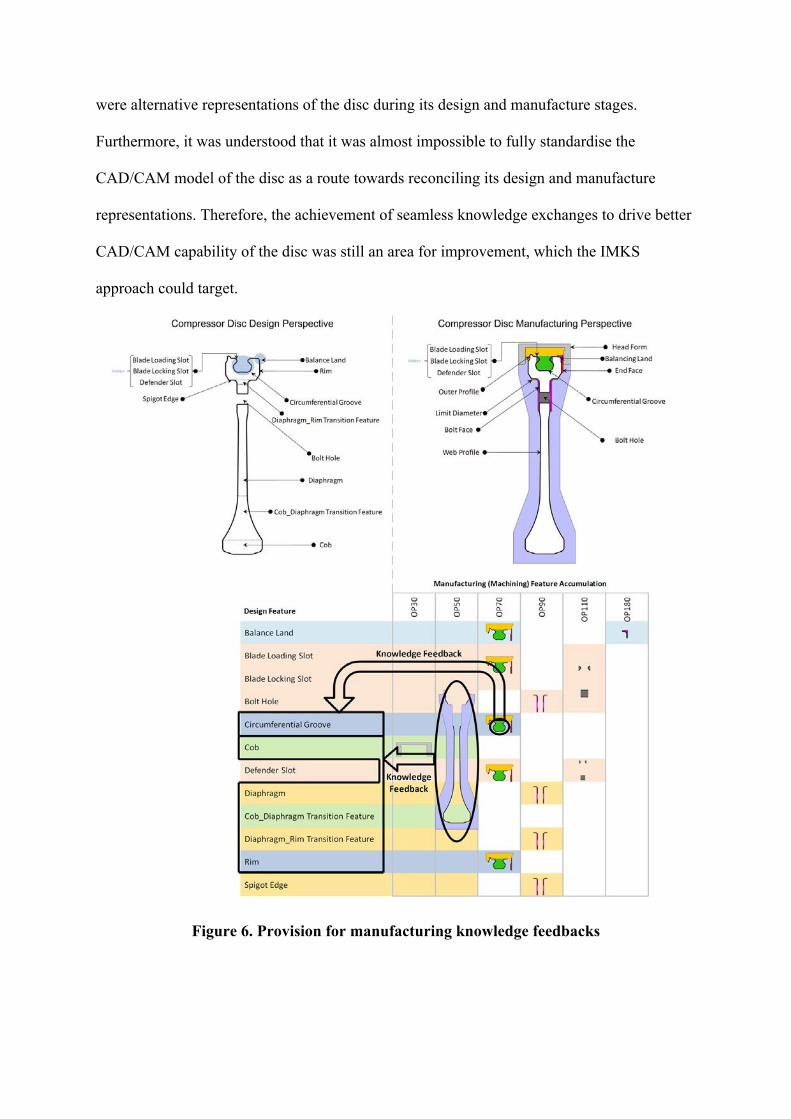
Figure 6. Provision for manufacturing knowledge feedbacks
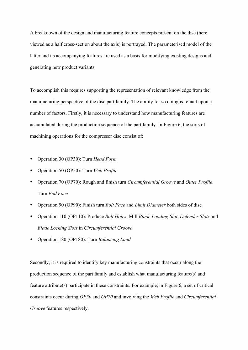
A breakdown of the design and manufacturing feature concepts present on the disc (here
viewed as a half cross-section about the axis) is portrayed. The parameterised model of the
latter and its accompanying features are used as a basis for modifying existing designs and
generating new product variants.
To accomplish this requires supporting the representation of relevant knowledge from the
manufacturing perspective of the disc part family. The ability for so doing is reliant upon a
number of factors. Firstly, it is necessary to understand how manufacturing features are
accumulated during the production sequence of the part family. In Figure 6, the sorts of
machining operations for the compressor disc consist of:
• Operation 30 (OP30): Turn Head Form
• Operation 50 (OP50): Turn Web Profile
• Operation 70 (OP70): Rough and finish turn Circumferential Groove and Outer Profile.
Turn End Face
• Operation 90 (OP90): Finish turn Bolt Face and Limit Diameter both sides of disc
• Operation 110 (OP110): Produce Bolt Holes. Mill Blade Loading Slot, Defender Slots and
Blade Locking Slots in Circumferential Groove
• Operation 180 (OP180): Turn Balancing Land
Secondly, it is required to identify key manufacturing constraints that occur along the
production sequence of the part family and establish what manufacturing feature(s) and
feature attribute(s) participate in these constraints. For example, in Figure 6, a set of critical
constraints occur during OP50 and OP70 and involving the Web Profile and Circumferential
Groove features respectively.

The third important factor demands understanding the direct mappings holding across the
design and manufacturing features, so that the knowledge from the manufacturing constraints
can be exploited in design stages. Figure 6 illustrates knowledge feeding back from the
Circumferential Groove manufacturing feature towards its counterpart in the design
perspective. The figure also depicts how manufacturing knowledge related to the Web Profile
has an implication on five design features to which it maps, i.e., a one-to-many mapping
exists in this case.
4.2. Specialised compressor disc ontology
The design and manufacturing perspectives of the compressor disc have been formalised and
all concepts, pertinent to the understanding in Figure 6, have been specialised from the
semantics of the Manufacturing Core Concepts ontology. Figure 7 captures important
structures within the implemented specialised compressor disc ontology. The Integrated
Ontology Development Environment (IODE) platform [37] has been used to deploy the
ontologies.
The diagram identifies a number of class specialisations such as (A) HPCDiscPF, i.e., high
pressure compressor disc part family which is a subtype of the core concept
DesignPartFamily and (B) CircumferentialGroove as a subtype of DesignFeature. Assertions
over classes are also present, e.g., (C) a set of feature attribute types that relate to
CircumferentialGroove and (D) the knowledge that HPCDiscPF holds
CircumferentialGroove as feature type. Note also that CircumferentialGroove as a type of
DesignFeature inherits core semantics dictating that it should have some associated Function

(E). A mapping assertion is also present which indicates that the CircumferentialGroove
definitions in the design and manufacturing perspectives are matching concepts.
Figure 7. Implementation of the specialised compressor disc ontology
In a similar way, the manufacturing representation of the compressor disc can be captured. In
Figure 7, two class specialisations (G) of the core concept ManufacturingPartFamily are
present. ManufacturingFeature has been specialised into a number of feature types, relevant
to the definition of the compressor disc manufacturing perspective, such as the highlighted
WebProfile class (H). The latter is a required feature type for part family definitions (I).
Furthermore, core semantics prescribe that subtypes of ManufacturingFeature require some
type of manufacturing method and in this example WebProfile has a WebProfileFMM, i.e., a

distinct feature manufacturing method for its production. Cross-domain feature mapping
assertions (K) are also present together with knowledge verification constraints, (L) and (M)
pertaining to CircumferentialGroove and WebProfile respectively, to support the
communication of manufacturing knowledge for improved decision making in design.
4.3. IMKS demonstration concept
The implementation of the specialised compressor disc ontology constitutes a key asset in
being able to tailor an ontology-driven PLM environment. Figure 8 depicts the IMKS
demonstration concept which exploits the combined use of a PLM software application with
the investigated ontology-based approach, notably:
• Siemens Teamcenter [22]: This environment is used by a designer to initiate the retrieval
of an HPCDiscPF individual. Teamcenter provides a platform for the organisation of part
families and features.
• Siemens NX [38]: This is the primary application with which the designer interacts in
order to receive feedback on the manufacturability of a number of features. Once a part
family individual has been retrieved from Teamcenter, the designer opens it in NX before
making design changes. When a new design has been completed, the designer validates it
according to existing manufacturing part family rules and constraints. These are held
within IODE.
• All ontology structures, including the Manufacturing Core Ontology and its
specialisations into the design and manufacturing perspectives of the compressor disc are
held in IODE. The Query and Facts Asserter tools are IODE functionalities for
interrogating and instantiating ontologies respectively.
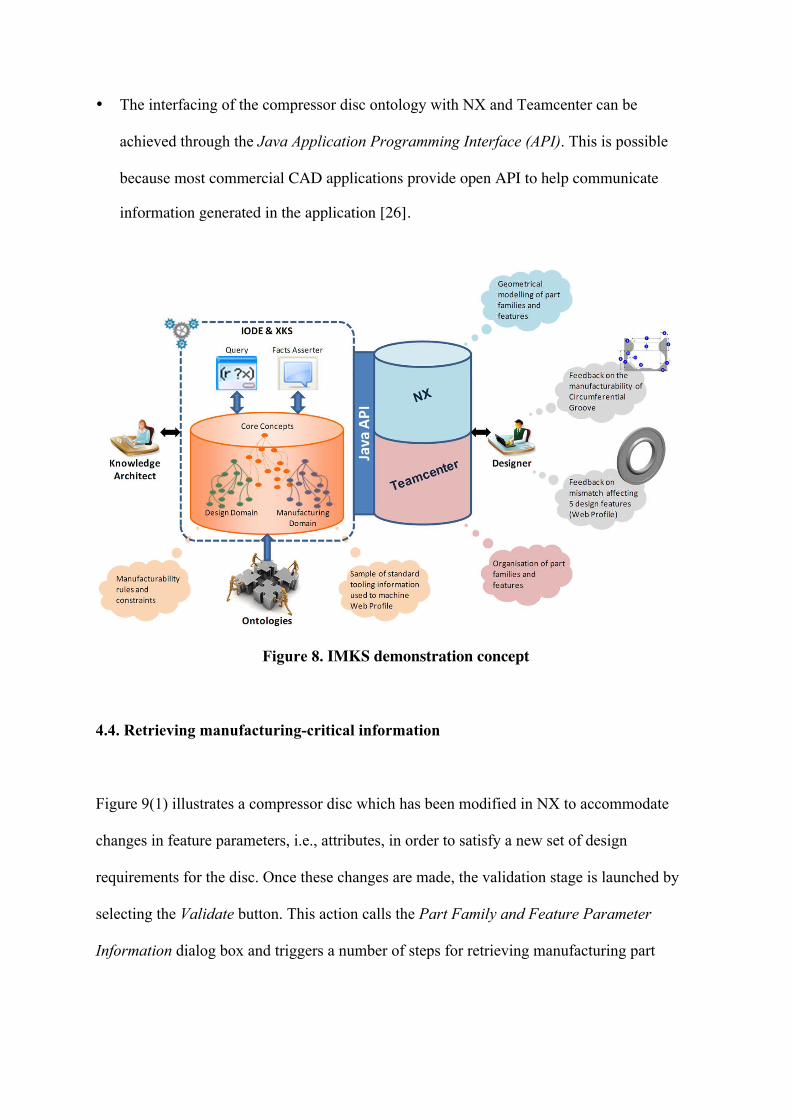
• The interfacing of the compressor disc ontology with NX and Teamcenter can be
achieved through the Java Application Programming Interface (API). This is possible
because most commercial CAD applications provide open API to help communicate
information generated in the application [26].
Figure 8. IMKS demonstration concept
4.4. Retrieving manufacturing-critical information
Figure 9(1) illustrates a compressor disc which has been modified in NX to accommodate
changes in feature parameters, i.e., attributes, in order to satisfy a new set of design
requirements for the disc. Once these changes are made, the validation stage is launched by
selecting the Validate button. This action calls the Part Family and Feature Parameter
Information dialog box and triggers a number of steps for retrieving manufacturing part

family and manufacturing-critical design features and their parameters, as shown in Figure
9(2). The steps are:
• (A): The API communicates the design part family from NX and Teamcenter to the
compressor disc ontology in IODE.
• (B): A KFL query is automatically generated to retrieve and display the associated
manufacturing part family type(s).
• (C): If there is more than one type of manufacturing part family the designer needs to
select the appropriate one. This decision is largely dependent on the site or factory at
which the part is to be produced. Selecting a manufacturing part family triggers another
KFL query which helps identify the design features which are critical from a
manufacturing viewpoint.
• (D): A further level of guidance is offered to the designer who can select a
manufacturing-critical design feature to view its corresponding critical feature
parameters. It is important to note that the ability to target the required knowledge is
dependent on generating the right queries. In the approach, it is clear that manufacturing-
critical entities always participate in knowledge verification constraints, and can therefore
be referenced appropriately.
• The designer then selects the Validate changes against manufacturing part family button
to complete the retrieval of manufacturing-critical information.
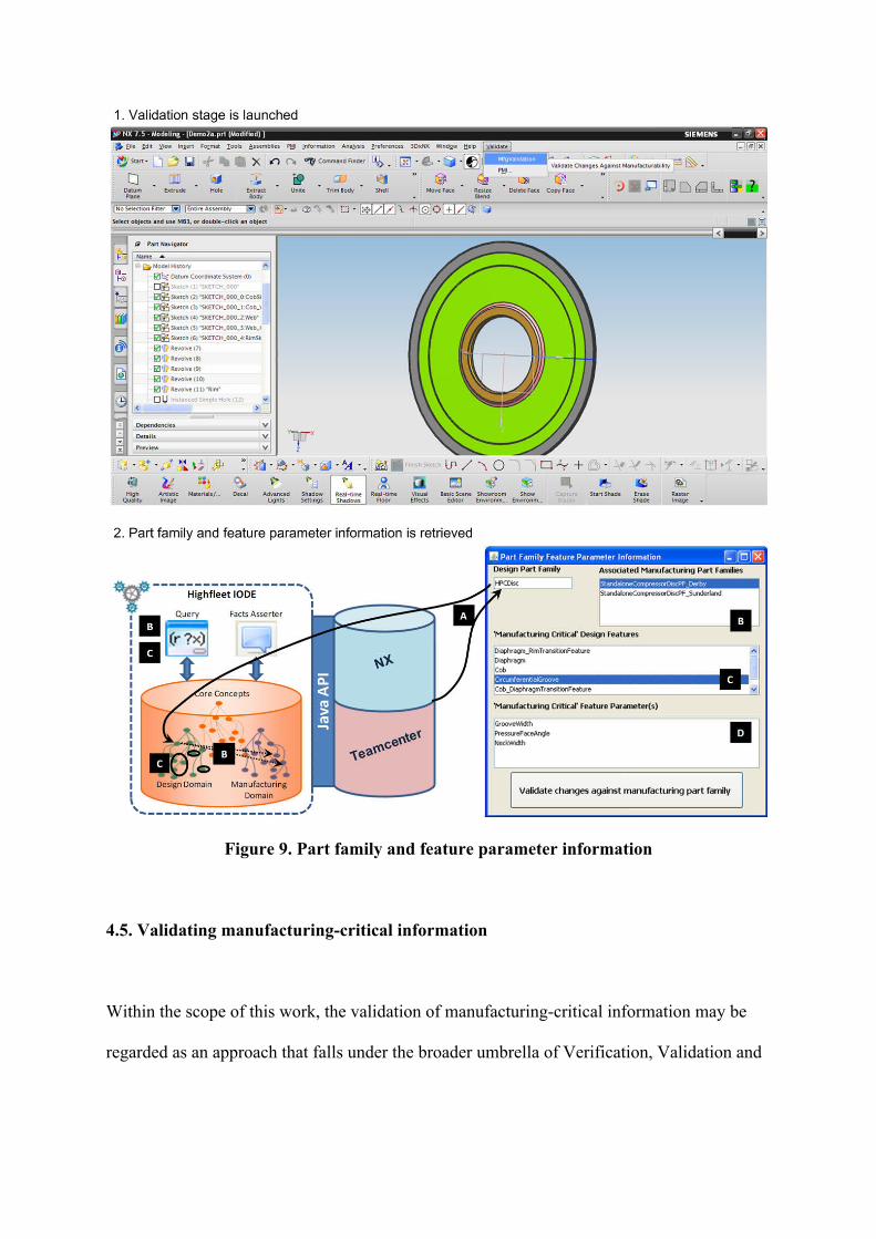
Figure 9. Part family and feature parameter information
4.5. Validating manufacturing-critical information
Within the scope of this work, the validation of manufacturing-critical information may be
regarded as an approach that falls under the broader umbrella of Verification, Validation and
Accreditation (VV&A) techniques [39], which are exploited to achieve the credibility and
acceptance of a formal approach.
Once the retrieval of manufacturing-critical information has been performed, the validation of
feature-relevant geometric values from the NX environment is then prompted. The following
stages complete the validation of manufacturing-critical information as shown in Figure 10.
• (A): The parameters and values gathered from NX are transferred using the API and
populated into the compressor disc ontology in IODE via the Facts Asserter.
• (B): The populated facts are assessed against the knowledge verification constraints
within the ontology.
• (C): If there is an infringement of a knowledge verification constraint, then, any violated
manufacturing feature related to that constraint is displayed in a new dialog box.
• (D): The designer selects a violated manufacturing feature to display its corresponding
design feature(s) which has participated in the infringement. In the example, the
WebProfile is one such violated manufacturing feature and the participating design
features are Cob and Rim.
• (E): When the designer selects a participating design feature, such as Rim, the related
parameter, i.e., design feature attribute that has contributed to the violated manufacturing
feature, is then displayed.
• (F): A further level of knowledge feedback is supported when the designer selects a
related parameter, e.g., OuterDiameter of the Rim. This knowledge comes from the
implicated violation constraint, more specifically the message carried by the knowledge
verification constraint. This message is vital for making the designer aware of the nature
of the issue in the designed part.

• (G): Using the validation results as a basis for decision making, the designer can choose
to undo parameter changes. Another option is to accept the changes made by selecting
Continue Anyway. However, this option is considered as not preferred as proceeding with
changes, which are known to lead to manufacturing issues, can potentially have
significant consequences during the product lifecycle. Another button, Find Alternative
Solutions, has been incorporated as a means of guiding the designer towards further
validation tasks such as contacting a manufacturing engineer or performing a collision
detection test to verify the suitability of different cutting tools for machining purposes.
Figure 10. Validation results
5. Discussion
The approach discussed in this article has demonstrated a motivating concept towards the
achievement of interoperability across the design and manufacture stages of the product
lifecycle. This has been made possible through the exploitation of mathematically-rigorous
ontologies that have been encoded in heavyweight format, to formally describe the meaning

of PLM system concepts. This implies that the IMKS approach has contributed to answering
the first related research question (see section 2.1).
However, the IMKS approach has yet to be extended and additional effort is, therefore,
required in order to progress into a more comprehensive framework recommendation to
achieve interoperable PLM system development. An interesting direction would be to relate,
apply and exploit the key functional blocks of the IMKS approach (see Figure 2) in the
context of the components of existing interoperability frameworks such as the framework for
enterprise interoperability [46] and the IDEAS interoperability framework [47], amongst
others.
Secondly, this work has specified a formal ontology of generic manufacturing concepts from
which individual design and manufacture domains can be extended. Together with the
experimented ontological mechanisms notably semantic constraints, subsumption, mappings
and knowledge verification constraints, the feasibility in the timely feedback of knowledge
from the manufacturing stages into design stages has been shown. This, therefore, tackles the
second research question (see section 2.1) addressed in this article.
It is, nevertheless, understood that not all knowledge can be captured in computational form.
Thus, the investigated approach does not intend to replace the engineer’s final decision but
exists as a means of supporting the exchange of general, agreed and recurrent knowledge at
different points throughout the product lifecycle. Furthermore, the implications of how to
maintain formal knowledge over time has fallen outside the scope of this work, thereby
implying a need to address ontology and knowledge maintenance. There is also an ongoing

need to drive the feedback of service knowledge, in addition to design and manufacturing
knowledge, as there are clear and related challenges that still need to be overcome [45].
The IMKS approach has also demonstrated, within its scope and experimental boundaries,
that a progression towards more rigorous semantic-based approaches can be of benefit for
tackling the challenges in managing the ability to share product, process and resource
knowledge. However, a confined scenario of process and resource knowledge affecting
product parameters has been implemented, leading to the relatively limited achievement in
tackling the third research question (see section 2.1). Hence, further scenarios have to be
identified and experimented so as to meet the needs towards approaches for the improvement
of product, process and resource lifecycle management [44].
From a usability perspective, the development of the ontologies presently requires a
knowledge architect who also needs to be familiar with the domain to be modelled (see
Figure 8). It would be helpful to subsequently consider the implications of having intelligent
interfaces for more intuitive ways of allowing non-ontology experts to interact with
ontologies and generating manufacturability constraints and rules. Moreover, the
‘interpretation and sharing’ functional block of the approach (see Figure 2G) would require
more effort for improving the workflows in the knowledge sharing module and the design of
GUIs that participate in that module.
In addition to this, the implementation of the IMKS approach has portrayed appropriate
interfacing capabilities across a set of vendor-specific applications. From the perspective of
adaptability to different PLM and CAD systems, it is understood that the interfacing

requirements across dissimilar platforms can be met, as long as the required APIs are
documented and made available for the implicated PLM, CAD and ontology environments.
6. Conclusions
The adoption of methods similar to the IMKS approach shall provide imminent positive
impact on the way that multiple product lifecycle applications interact for delivering
knowledge sharing capability at the right place and time.
However, it should not be forgotten that there exists a number of areas which deserve further
attention, e.g., change management of current information-driven systems into knowledge-
driven systems, ontology management, knowledge maintenance and through-life engineering
knowledge feedback. Opportunities are also present for extending the current Manufacturing
Core Ontology into a much richer model with structures to capture, e.g., assembly, shop-floor
and service knowledge.
Finally, based on the understanding displayed in this work, it is possible to extrapolate that
there are two main directions for further exploiting the IMKS approach. Firstly, it can be
utilised as a short term solution, targeting an incremental improvement, that supplements
existing PLM systems with an expressive ontological basis to provide meaning to PLM
concepts and to harvest the benefits of semantic definitions and rule-bases.
The other possibility, which is for longer term prospect with radical improvement, would be
to utilise the IMKS approach as a method to deliver PLM system development from scratch.

Instead of data and information models, the emphasis would be on logic-based knowledge
models for system design and implementation. Regardless of the pursued direction, the
advantages of knowledge over information and data would be gained, which is especially
pertinent to complex manufacturing-centric ecosystems that generate product, process,
resource and service knowledge.
Acknowledgements
This work has been supported by the Engineering and Physical Sciences Research Council
under project 253 of the Loughborough University Innovative Manufacturing and
Construction Research Centre (IMCRC). We also wish to thank our industrial partners
notably Rolls-Royce, Highfleet, Siemens, Ford and Emergent Systems, who have
collaborated in the Interoperable Manufacturing Knowledge Systems (IMKS) project.
References
1. Abramovici M. Future trends in product lifecycle management (PLM). In: Krause F-L
(ed.) The future of product development. Proceedings of the 17th CIRP design conference,
Berlin, Germany, March 27-28. Berlin: Springer-Verlag, 2007, pp. 665–674.
2. Chandra C and Kamrani AK. Knowledge management for consumer-focussed product
design. Journal of Intelligent Manufacturing 2003; 14: 557–580.
3. Young RIM, Gunendran AG, Cutting-Decelle A-F and Gruninger M. Manufacturing
knowledge sharing in PLM: a progression towards the use of heavy weight ontologies.
International Journal of Production Research, 2007; 45(7): 1505–1519.
4. Gómez-Pérez A, Fernández-López M and Corcho O. Ontological engineering: with
examples from the areas of knowledge management, e-commerce and the semantic web.
London: Springer-Verlag, 2004.
5. Kim K-Y, Manley DG and Yang H. Ontology-based assembly design and information
sharing for collaborative product development. Computer-Aided Design, 2006; 38: 1233–
1250.
6. Chungoora N. A framework to support semantic interoperability in product design and
manufacture (PhD). Loughborough University, 2010.
7. Chungoora N and Young RIM. The configuration of design and manufacture knowledge
models from a heavyweight ontological foundation. International Journal of Production
Research, 2011; 49(15): 4701–4725.
8. Zheng LY, McMahon CA, Li L, Ding L and Jamshidi J. Key characteristics management
in product lifecycle management: a survey of methodologies and practices. Proceedings
of the IMechE Part B: Journal of Engineering Manufacture, 2008; 222(8): 989–1008.
9. Hoffman CM and Joan-Arinyo R. CAD and the product master model. Computer-Aided
Design, 1998; 30(11): 905–918.
10. Raine JK, Pons, D and Whybrew K. The design process and a methodology for system
integrity. Proceedings of the IMechE Part B: Journal of Engineering Manufacture, 2001;
215(4): 569–576.
11. Kugathasan P and McMahon CA. Multiple viewpoint design models for automotive
body-in-white design. International Journal of Production Research, 2001; 39(8): 1689–
1705.
12. Interoperable Manufacturing Knowledge Systems (IMKS).
http://www.lboro.ac.uk/departments/mm/research/product-realisation/imks/index.html
(accessed July 2011)
13. Knowledge Frame Language (KFL) reference. Document supplied with the installation of
Highfleet Integrated Ontology Development Environment (IODE), 2010.
14. ISO/IEC 24707. Information technology – Common Logic: a framework for a family of
logic-based languages. Geneva, Switzerland: International Organization for
Standardization (ISO), 2007.
15. Usman Z, Young RIM, Chungoora N, Palmer C, Case K and Harding JA. A
manufacturing core concepts ontology for product lifecycle interoperability. In: van
Sinderen M and Johnson P (eds.) Enterprise interoperability. Proceedings of the 3rd
International IFIP Working Conference on Enterprise Interoperability (IWEI), Stockholm,
Sweden, March 23-24. Germany: Springer, 2011, pp. 5–18.

16. Subrahmanian E, Sudarsan R, Fenves SJ, Foufou S and Sriram RD. Challenges in
supporting product design and manufacturing in a networked economy: a PLM
perspective. In: Bouras A, Gurumoorthy B and Sudarsan R (eds.) Product Lifecycle
Management: Emerging solutions and challenges for Global Networked Enterprise.
Proceedings of the PLM'05 international conference on product lifecycle management,
Lyon, France, July 11-13. Geneva: Inderscience Enterprises Ltd, 2005, pp. 495–506.
17. Mostefai S and Bouras A. What ontologies for PLM: a critical analysis. Proceedings of
the 12th international conference on concurrent enterprising, Milan, Italy, June 26–28,
2006, pp. 423-430.
18. Anjum NA, Harding JA and Young RIM. Cross domain knowledge verification:
Verifying knowledge in foundation based domain ontologies. Proceedings of the
International Conference on Knowledge Engineering and Ontology Development
(KEOD), Valencia, Spain, October 25-28, 2010.
19. Patil L, Dutta D and Sriram R. Ontology based exchange of product data semantics. IEEE
Transactions on Automation Science and Engineering 2005; 2(3): 213–225.
20. Fiorentini X, Gambino I, Liang V-C, Rachuri S, Mani M and Bock C. An ontology for
assembly representation. NISTIR 7436, National Institute of Standards and Technology,
2007.

21. Raza MB, Kirkham T, Harrison R and Reul Q. Knowledge based flexible and integrated
PLM system at Ford. Journal of Information and Systems Management 2011; 1(1): 8–16.
22. Siemens Teamcenter.
http://www.plm.automation.siemens.com/en_us/products/teamcenter/ (accessed July
2011).
23. Web Ontology Language (OWL): OWL web ontology language overview.
http://www.w3.org/TR/owl-features/ (2006, accessed July 2011).
24. Franke M, Klein P, Schroder L and Thoben K-D. Ontological semantics of standards and
PLM repositories in the product development phase. In: Bernard A (ed.) Global product
development. Proceedings of the 20th CIRP design conference, Nantes, France, April 19-
21 2010. Germany: Springer-Verlag, 2011, pp. 473–483.
25. Matsokis A and Kiritsis D. An ontology-based approach for product lifecycle
management. Computers in Industry 2010; 61: 787–797.
26. Zhan P, Jayaram U, Kim O and Zhu L. Knowledge representation and ontology mapping
methods for product data in engineering applications. Journal of Computing and
Information Science in Engineering 2010; 10(2): 699–715.
27. Rabe M and Gocev P. Semantic web framework for rule-based generation of knowledge
and simulation of manufacturing systems. In: Mertins K, Ruggaber R, Popplewell K and

Xu X (eds.) Enterprise interoperability III: new challenges and industrial approaches.
London: Springer-Verlag, 2008, pp. 397–409.
28. Kesavadas MP, Peygude A, Bandi K. Development of formal ontology for product design
lifecycle. In: Bouras A, Gurumoorthy B and Sudarsan R (eds.) Product lifecycle
management: emerging solutions and challenges for Global Networked Enterprise.
Proceedings of the PLM'05 international conference on product lifecycle management,
Lyon, France, July 11-13. Geneva: Inderscience Enterprises Ltd, 2005, pp. 3–10.
29. Borgo S and Leitão P. Foundations for a core ontology of manufacturing. In: Sharman R,
Kishore R and Ramesh R (eds.) Ontologies: a handbook of principles, concepts and
applications in information systems. New York: Springer, 2008, pp. 751–776.
30. Fenves SJ, Foufou S, Bock C and Sriram RD. CPM: a core product model for product
data. Journal of Computing and Information Science in Engineering 2005; 5: 238–246.
31. Lee J-H and Suh H-W. Ontology-based multi-layered knowledge framework for product
lifecycle management. Concurrent Engineering: Research and Applications 2011; 16(4):
301–311.
32. Wang F, Fenves SJ, Sudarsan R and Sriram R. Towards modelling the evolution of
product families. Proceedings of the ASME 2003 international design engineering
conferences and computers and information in engineering conference, Chicago, USA,
September 2-6 2003, pp. 421–430.
33. Gunendran AG and Young RIM. Methods for the capture of manufacture best practice in
product lifecycle management. In: Bouras A, Gurumoorthy B, McMahon R and Ramani
K (eds.) Product lifecycle management: fostering the culture of innovation. Proceedings
of the PLM'08 international conference on product lifecycle management, Seoul, Korea,
July 9-11. Geneva: Inderscience Enterprises Ltd, 2008, pp. 3–10.
34. ISO 10303-239. Industrial automation systems and integration – product data
representation and exchange – part 239: application protocol: product life cycle support.
Geneva, Switzerland: International Organization for Standardization (ISO), 2005.
35. ISO 15531-44. Industrial automation systems and integration – industrial manufacturing
management data – part 44: information modelling for shop floor data acquisition.
Geneva, Switzerland: International Organization for Standardization (ISO), 2010.
36. ISO 18629-1. Industrial automation systems and integration – process specification
language – part 1: overview and basic principles. Geneva, Switzerland: International
Organization for Standardization (ISO), 2004.
37. Integrated Ontology Development Environment (IODE).
http://www.highfleet.com/iode.html (accessed July 2011).
38. Siemens NX. http://www.plm.automation.siemens.com/en_us/products/nx/ (accessed July
2011).

39. Youngblood M, Pace DK, Eirich PL, Gregg DM and Coolahan JE. Simulation
verification, validation and accreditation. John Hopkins APL Technical Digest 2000;
31(3); 359–367.
40. Widening appreciation of PLM: investing in delivering innovation. Strategic Direction,
2005, 21(9); 35–37, Emerald Group Publishing Limited.
41. Raine JK, Pons D and Whybrew K. The design process and a methodology for system
integrity. Proceedings of the IMechE Part B: Journal of Engineering Manufacture, 2001;
215(4): 569–576.
42. Le Digou J, Bernard A, Perry N and Delplace J-C. Generic model for the implementation
of PLM systems in mechanical SMEs. Proceedings of the7th international conference on
product lifecycle management, Bremen, Germany, July 12-14 2010.
43. Baokar S. Interoperability in the PLM ecosystem: industry approaches. White paper,
Geometric Limited.
http://products.geometricglobal.com/solutions/downloads/Geometric%20Interoperability`
%20in%20PLM%20Ecosystem.pdf (2008, accessed July 2012).
44. Haq I, Masood T, Ahmed B, Harrison R, Raza B and Monfared RP. Product to process
life cycle management in assembly automation systems. Proceedings of the 7th
international conference on digital enterprise technology (DET-2011), Athens, Greece,
September 28-30 2011, pp.467–477.
45. Masood T, Roy R, Harrison A, Gregson S, Xu Y and Reeve C. Challenges in digital
feedback of through-life engineering service knowledge to product design and
manufacture. Proceedings of the 7th international conference on digital enterprise
technology (DET-2011), Athens, Greece, September 28-30 2011, pp. 447–457.
46. CEN/ISO 11354. Requirements for establishing manufacturing enterprise process
interoperability – part 1: framework for enterprise interoperability. Geneva, Switzerland:
International Organization for Standardization (ISO), 2008.
47. Chen D, Knothe T and Zelm M. ATHENA integrated project and the mapping to
international standard ISO 15704. In: Bernus P and Fox M (eds.) Knowledge sharing in
the integrated enterprise: interoperability strategies for the enterprise architect. USA:
Springer, 2005, pp. 67–77.
48. Cascini G, Giovani G, Rissone P and Rotini F. Integrated design of turbomachinery
through a STEP-XML platform for data exchange. Proceedings of the IMechE Part B:
Journal of Engineering Manufacture, 2005; 219(7): 547–554.
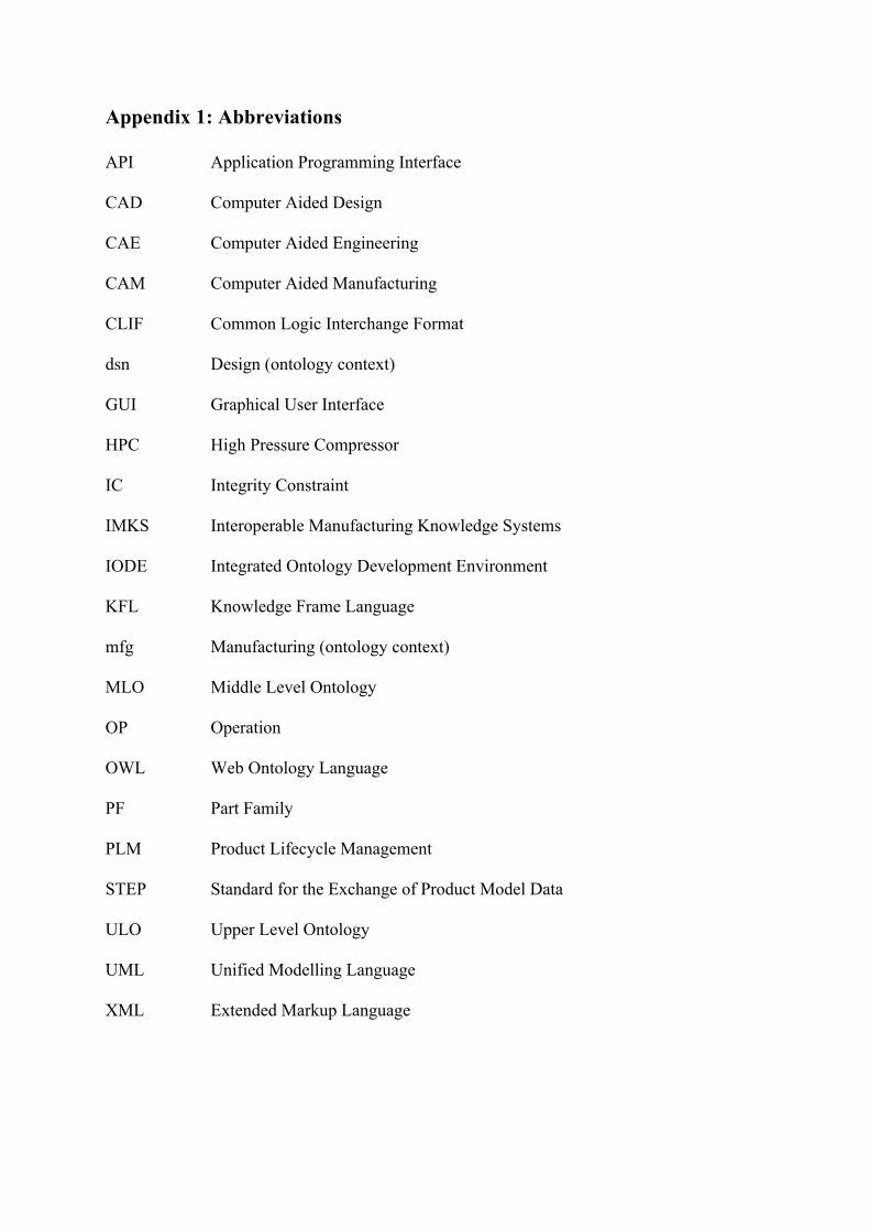
Appendix 1: Abbreviations
API Application Programming Interface
CAD Computer Aided Design
CAE Computer Aided Engineering
CAM Computer Aided Manufacturing
CLIF Common Logic Interchange Format
dsn Design (ontology context)
GUI Graphical User Interface
HPC High Pressure Compressor
IC Integrity Constraint
IMKS Interoperable Manufacturing Knowledge Systems
IODE Integrated Ontology Development Environment
KFL Knowledge Frame Language
mfg Manufacturing (ontology context)
MLO Middle Level Ontology
OP Operation
OWL Web Ontology Language
PF Part Family
PLM Product Lifecycle Management STEP Standard for the Exchange of Product Model Data ULO Upper Level Ontology UML Unified Modelling Language XML Extended Markup Language
Related Documents