Extended Finite Element Method XFEM Dorota Byrska November 3, 2010

Welcome message from author
This document is posted to help you gain knowledge. Please leave a comment to let me know what you think about it! Share it to your friends and learn new things together.
Transcript
Extended Finite Element MethodXFEM
Dorota ByrskaNovember 3, 2010
2
Plan of presentation
Motivation General idea of XFEM
XFEM enrichment in 1D XFEM enrichment in 2D
Numerical Integration in XFEM Blending elements XFEM implementation Simple example
3
Motivation
Difficulties in modeling discontinuous field by FEM
Necessity of remeshing in FEM High computational cost of FEM Low accuracy of FEM in modeling cracks
4
General idea of XFEM
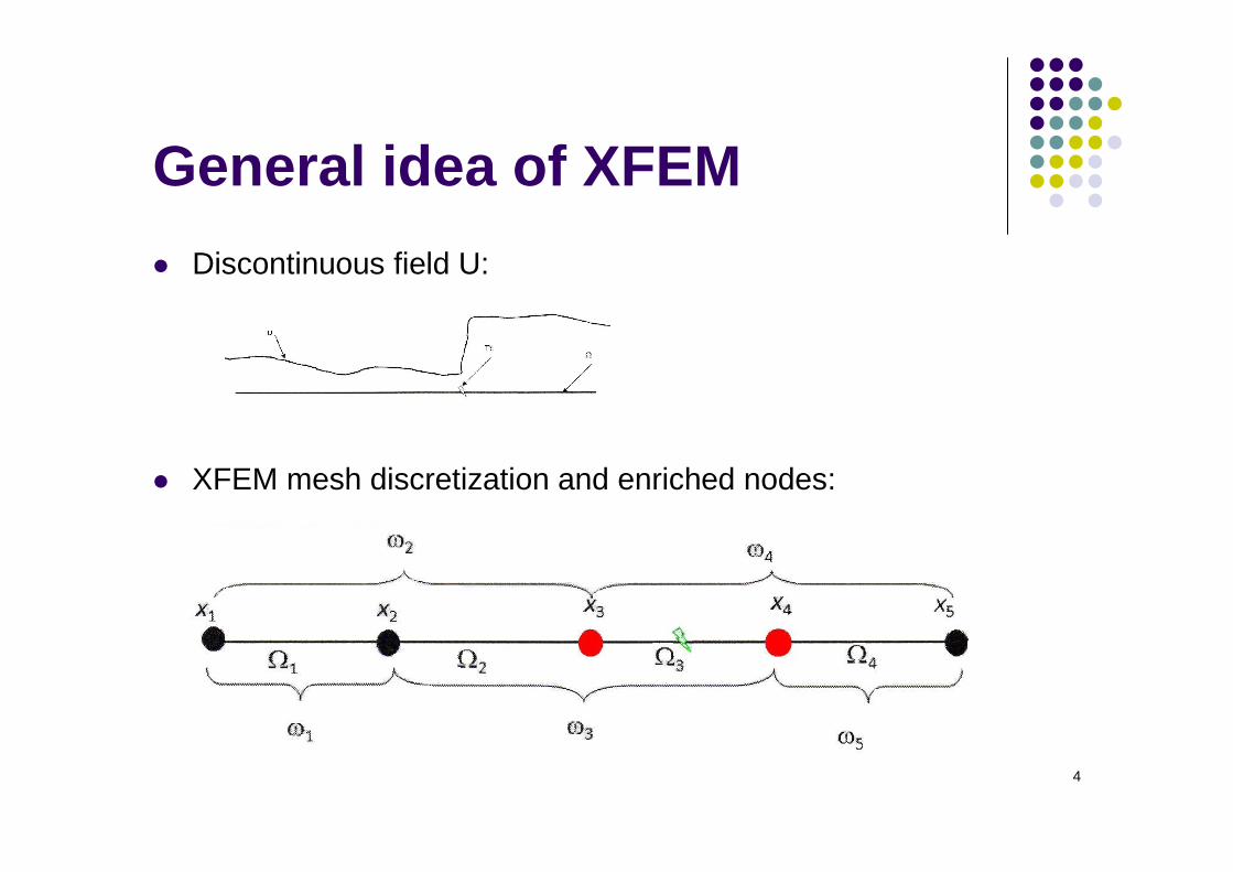
Discontinuous field U:
XFEM mesh discretization and enriched nodes:
5
General idea of XFEM
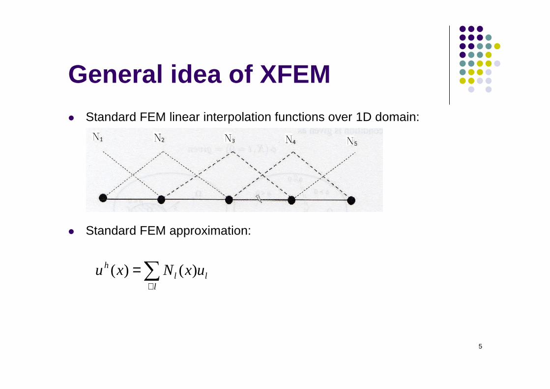
Standard FEM linear interpolation functions over 1D domain:
Standard FEM approximation:
∑∀
=l
llh uxNxu )()(
6
General idea of XFEM
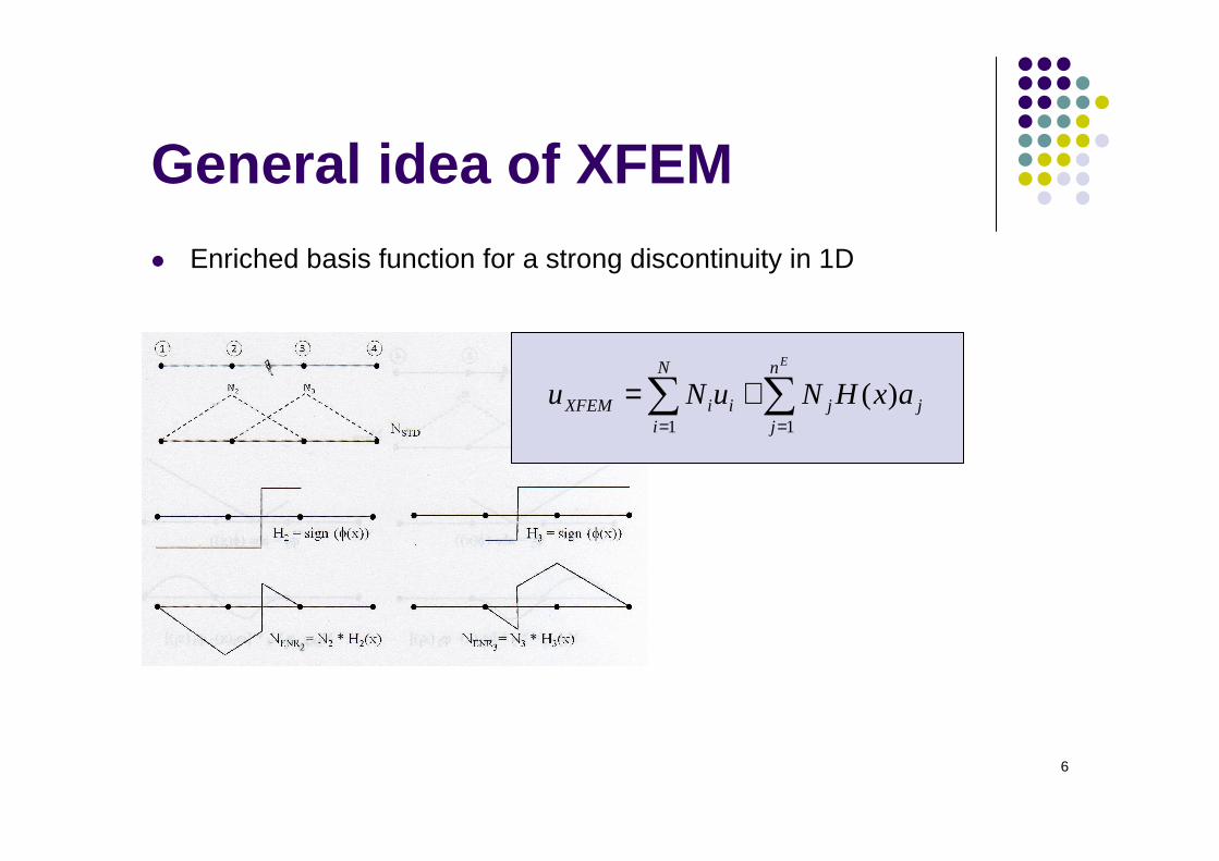
Enriched basis function for a strong discontinuity in 1D
∑∑==
+=En
jjj
N
iiiXFEM axHNuNu
11
)(
7
General idea of XFEM
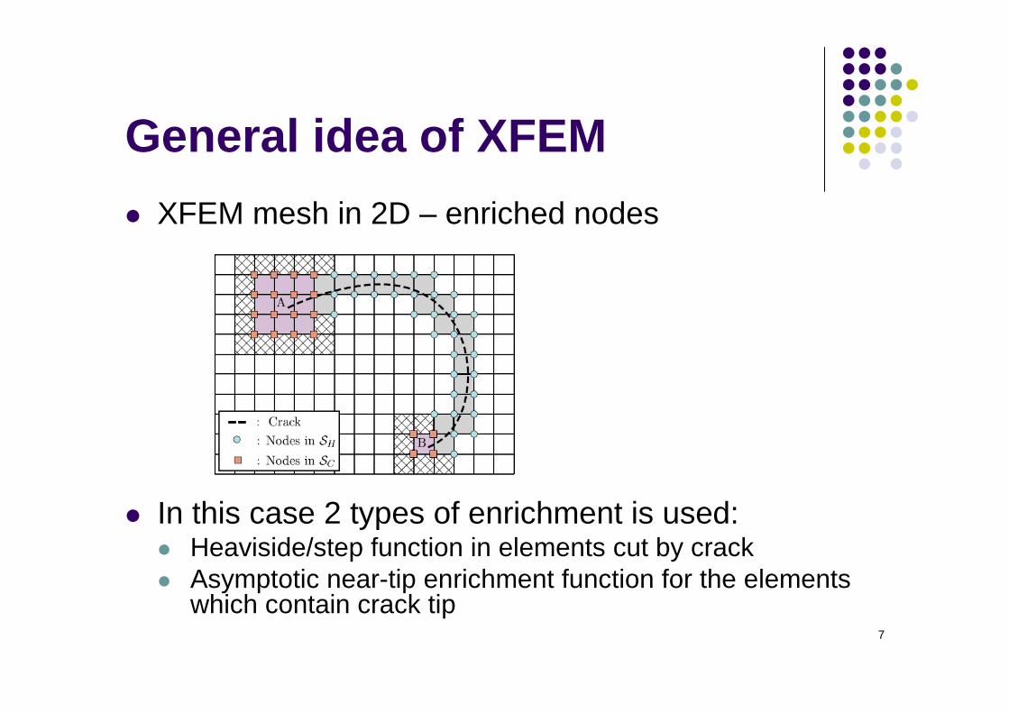
XFEM mesh in 2D – enriched nodes
In this case 2 types of enrichment is used: Heaviside/step function in elements cut by crack Asymptotic near-tip enrichment function for the elements
which contain crack tip
8
General idea of XFEM
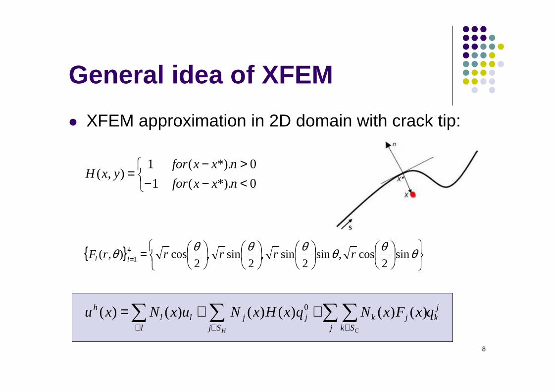
XFEM approximation in 2D domain with crack tip:
<−−>−
=0*).(1
0*).(1),(
nxxfor
nxxforyxH
== θθθθθθθ sin2
cos,sin2
sin,2
sin,2
cos),( 4
1 rrrrrF ll
jk
Sj j Skjkjj
lll
h qxFxNqxHxNuxNxuH C
∑ ∑∑∑∈ ∈∀
++= )()()()()()( 0
9
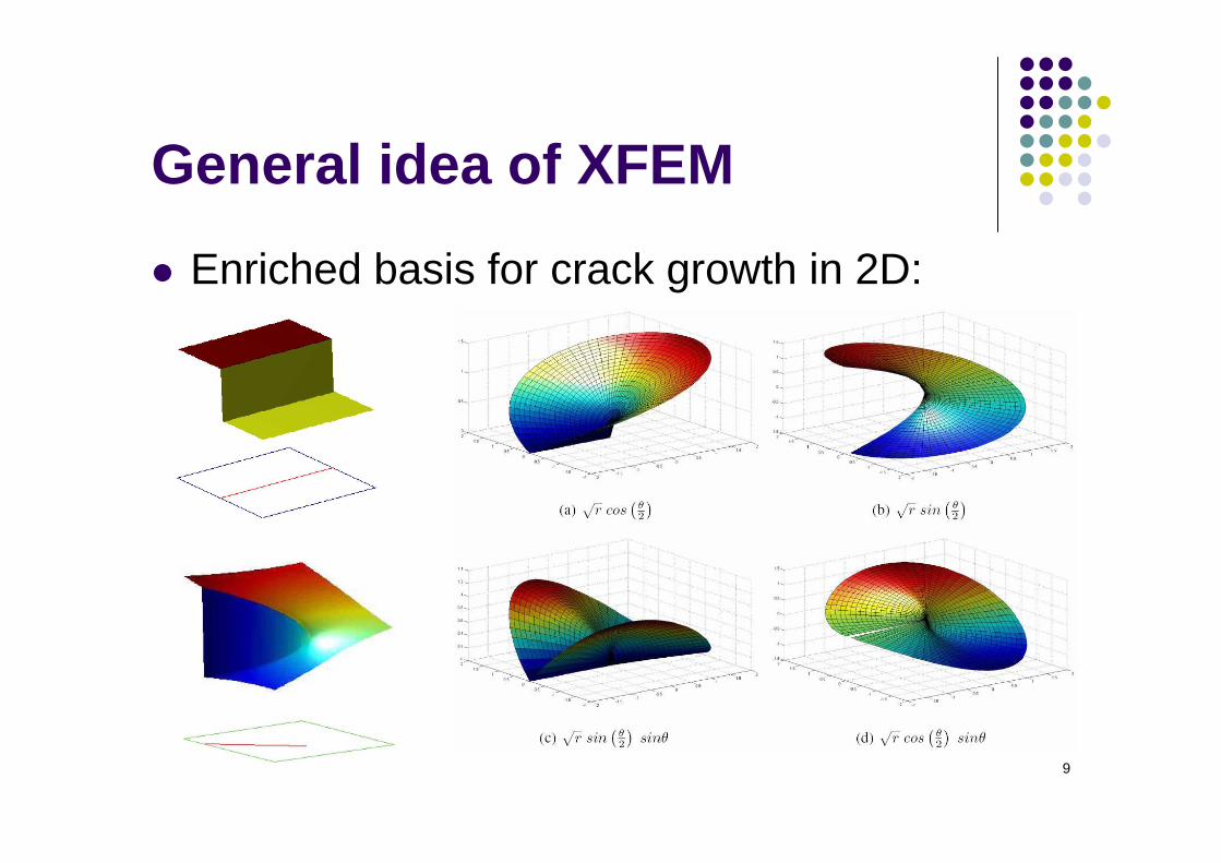
General idea of XFEM
Enriched basis for crack growth in 2D:
10
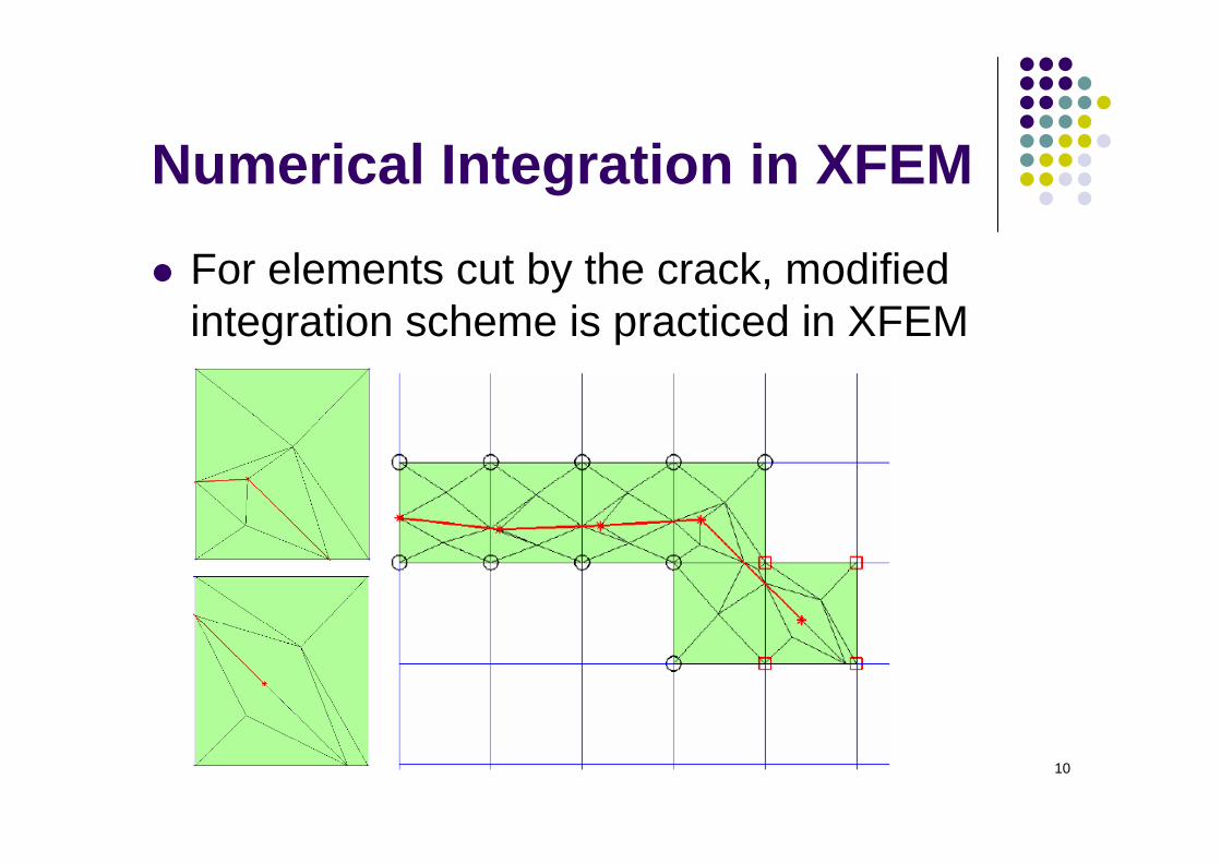
Numerical Integration in XFEM
For elements cut by the crack, modified integration scheme is practiced in XFEM
11
Numerical Integration in XFEM
The partitioning of an element is done only for integration purpose and no extra degrees of freedoms are added to the system unlike the usual FEM
No conditions on the shape of sub-polygons or sub-triangles is imposed
12
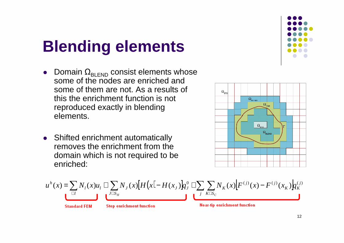
Blending elements Domain ΩBLEND consist elements whose
some of the nodes are enriched and some of them are not. As a results of this the enrichment function is not reproduced exactly in blending elements.
Shifted enrichment automatically removes the enrichment from the domain which is not required to be enriched:
( )[ ] [ ] )()()(0 )()()()()()()( jK
j SKK
jjKJ
l SJJJll
h qxFxFxNqxHxHxNuxNxuCH
∑ ∑∑ ∑∈∀ ∈
−+−+=
13
Crack initiation and growth
Some of the commonly used crack growth criteria are: Minimum strain energy density criteria Maximum energy release rate criteria Maximum hoop stress or maximum principal
stress criteria Global tracking algorithm
14
Crack initiation and growth
Minimum strain energy density criteria
The crack initiation will occur when the minimum of the strain energy density function S reaches to some critical value Scr
The crack will extend in a direction in which strain energy density factor possess a minimum value
15
Crack initiation and growth
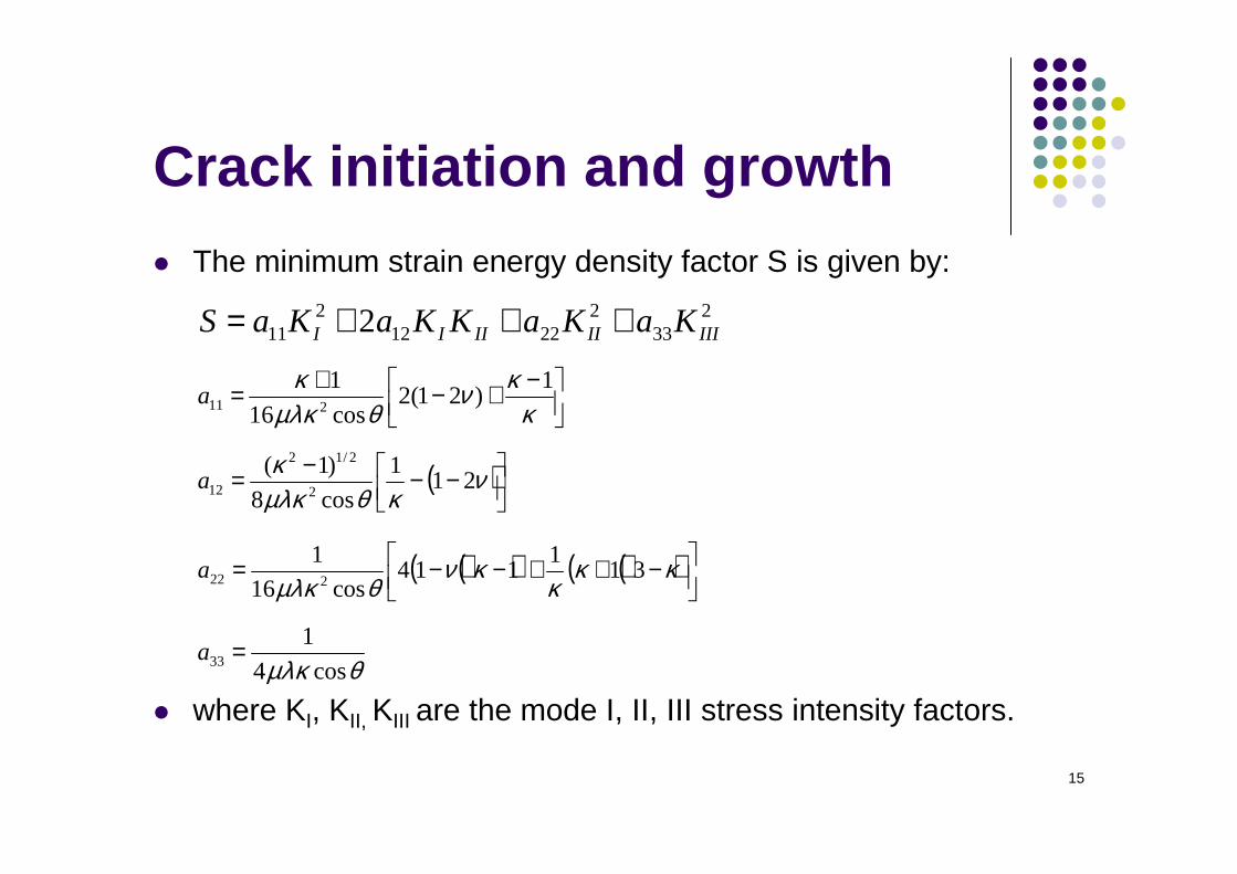
The minimum strain energy density factor S is given by:
where KI, KII, KIII are the mode I, II, III stress intensity factors.
233
22212
211 2 IIIIIIIII KaKaKKaKaS +++=
−+−+=κ
κνθµλκ
κ 1)21(2
cos16
1211a
( )
−−−= νκθµλκ
κ21
1
cos8
)1(2
2/12
12a
( )( ) ( )( )
−++−−= κκκ
κνθµλκ
311
114cos16
1222a
θµλκ cos4
133 =a
16
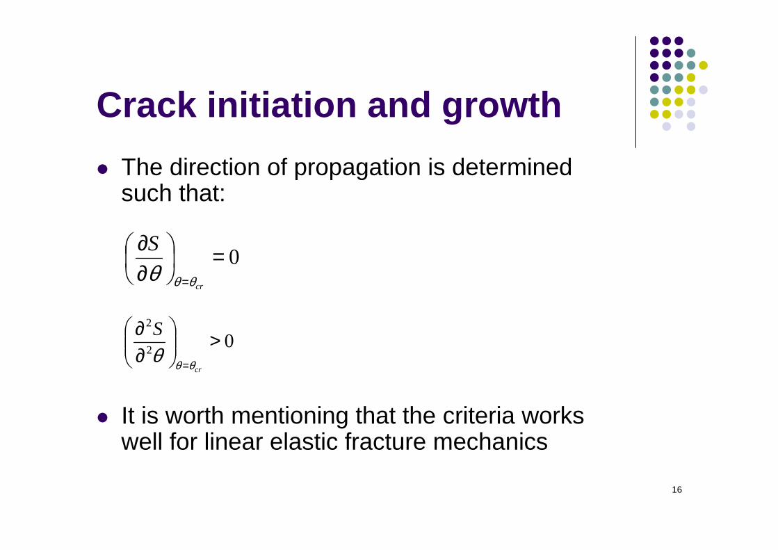
Crack initiation and growth
The direction of propagation is determined such that:
It is worth mentioning that the criteria works well for linear elastic fracture mechanics
0=
∂∂
= cr
S
θθθ
02
2
>
∂∂
= cr
S
θθθ
17
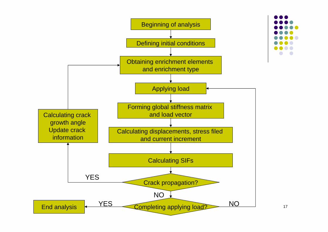
Beginning of analysis
Defining initial conditions
Obtaining enrichment elements and enrichment type
Applying load
Forming global stiffness matrix and load vector
Calculating displacements, stress filed and current increment
Calculating SIFs
Crack propagation?
Calculating crack growth angleUpdate crack
information
Completing applying load?
YES
NONOEnd analysis YES
18
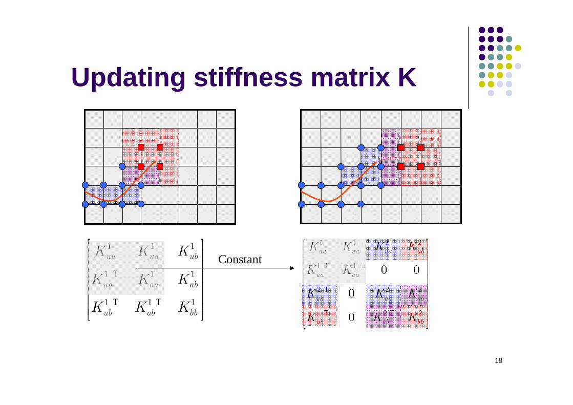
Updating stiffness matrix K
Constant
19
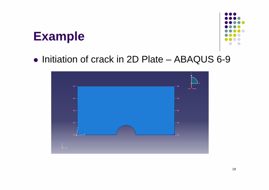
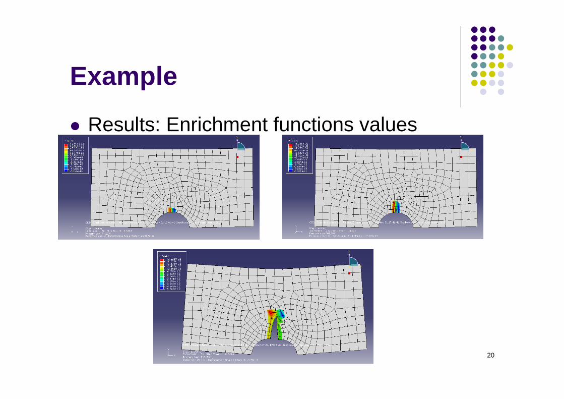
Example
Initiation of crack in 2D Plate – ABAQUS 6-9
20
Example
Results: Enrichment functions values
21
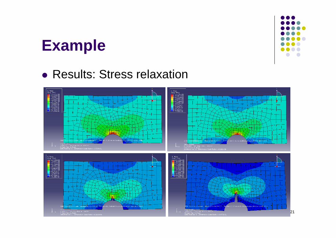
Example
Results: Stress relaxation
22
Conclusion
Better accuracy of XFEM in comparison to FEM
Re-meshing is not need Possibility of modeling discontinuities and
singularities by XFEM Lower computationally cost
23
References T. Belytschko, R. Gracie, G. Ventura, A review of extended/generalized
finite element methods for material modeling, Modeling Simul. Mater. Sci. Eng. 17 (2009)
Y. Abdelaziz, A. Hamouine, A survey of the extended finite element, Computers & Structures, Volume 86, Issue 11-12, June 2008, Pages 1141-1151
N. Moës, J. Dolbow, T. Belytschko, A finite element method for crack growth without remeshing, Int. J. Numer. Meth. Engng. 46, 131-150 (1999)
http://www.xfem.rwth-aachen.de/
http://dilbert.engr.ucdavis.edu/~suku/xfem/

24
Thank you for your attention
Related Documents