Journal of Advanced Concrete Technology Vol. 13, 193-204, March 2015 / Copyright © 2015 Japan Concrete Institute 193 Scientific paper Exploring the Potential of the Functionally Graded SCCC for Developing Sustainable Concrete Solutions Olga Río 1* , Viet Duc Nguyen 2 and Khan Nguyen 2 A selected paper of ICCS13, Tokyo 2013. Received 25 October 2013, accepted 16 February 2015 doi:10.3151/jact.13.193 Abstract The feasibility of using layered- Functionally Graded Self Compacting Cement Composite (FGSCCC) for precast shield-tunnel segments, in harmony with present concrete industry sustainability trend, is presented herein. Limestone powder-type Self-Compacting Cement Composites (SCCC) either with silica fume (SiF) or with SiF and steel fibres (SF) were formulated for the watertight layer. While, SCCC with polypropylene fibres (PPF) or light weight aggregates and SF (LWA+SF) were used for the fire-resistant ones. Besides, a high strength SCCC (HS-SCCC) was considered for structural layers and monolithic samples. Layer composition influence and interlayer robustness on the structural ele- ment properties were evaluated. Experiments showed that the FGSCCCs are more effective than the HS-SCCC solu- tions in front of water, chloride, carbonation, fire or in terms of residual strength. Thanks to its precise spatial material arrangement, the effect of fire or the risk of steel reinforcement corrosion substantially decreases. The residual compres- sive strength, of FGSCCC specimens with LWA+SF layers, slightly decreases compared to that with PPF layers. Fur- thermore, they showed the increase of toughness of these specimens. Although none sharp failure at interface was ob- served, the results pointed out the necessity of considering other different effective parameters for validating the signifi- cance of casting process based on rheology. 1. Introduction Most concrete elements are precast using the same con- crete technology in their totality (Han et al. 2005; Ot- remba and Kessler 2009; Caratelli et al. 2011). This effective methodology for guaranteeing structural safety and improving service life results in an inefficient use of resources and in greatest material costs (Otremba and Kessler 2009, Dias et al. 2010). This issue is particu- larly noted for the precast segments of road or railway tunnels placed under sea water. These segments, must be resilient to water ingress (Franzen and Celestino 2002; Gomes 2005; Gall and Soe 2011) and to fire events (Kodur and Phan 2007; Kim et al. 2010; Alonso et al. 2011) under conditions of use and also to precast and sometimes unforeseen mechanized production ac- tions (Río 2009; Caratelli et al. 2011). A significant state of art design criterion, applied to tunnel segments nowadays, is to adopt not standard mix proportions involving also the use of fibres (Han et al. 2005; Otremba and Kessler 2009; Caratelli et al. 2011). Nevertheless, in most cases, the adoption of waterproof and/or fire sprayed additional layers cannot be avoided (Kim et al. 2010). Moreover, from a structural point of view, a major disadvantage of these layering techniques has been the resulting relative poor bonding strength which leads to delamination failures (Dias et al. 2010). Therefore, the key point to merge advantages of both techniques is applying the Functionally Graded Material (FGM) concept (Bever and Duwez 1972; Maalej et al. 2003). The concept allows eliminating the material- property discontinuities by grading the material compo- sition near the interfaces and varying the material among layers, which results in a most cost-efficient multifunctional material. Typical examples can be found in Maalej et al. (2003), Shen et al. (2008), Baoguo et al. (2009), Dias et al. (2010), Bosch et al. (2010) and Wen et al. (2010). Though, the significant advantages of these different layered- Functionally Graded Cement Composites (FGCCs) they still involve significant pro- duction process and/or sectional design drawbacks (Río 2009). Self-compacting cement composites (SCCC) is a fairly new type of flowable fill material. This property that can be achieved by proper balance between con- stituent materials could broaden also the possibilities for improving the FGCC concept. As it has been demon- trated, SCCC properties allow self-producing FGCC with constant dimension layers and tiny robust interlay- ers of about 2-4 mm (Río et al. 2013) which compare with the 20-50 mm produced with most costly casting methods (Ho et al, 2004; Baoguo et al. 2009; Bosch et al. 2010) is a significant advantage in terms of sectional design. This fact, and the identifiable benefits of the SCCC for improving production, makes the named as FGSCCC concept (Río et al. 2013) a good candidate for developing sustainable concrete solutions. Nevertheless, limited research was conducted to test and analyse pre- cast FGSCCC as that needed for tunnel segments. In this paper, this FGSCCC concept is adopted to 1 Eduardo Torroja Institute for Construction Sciences, CSIC, Madrid, Spain. *Corresponding author, E-mail: [email protected] 2 Eduardo Torroja Institute for Construction Sciences, CSIC, Madrid, Spain.

Welcome message from author
This document is posted to help you gain knowledge. Please leave a comment to let me know what you think about it! Share it to your friends and learn new things together.
Transcript

Journal of Advanced Concrete Technology Vol. 13, 193-204, March 2015 / Copyright © 2015 Japan Concrete Institute 193
Scientific paper
Exploring the Potential of the Functionally Graded SCCC for Developing Sustainable Concrete Solutions Olga Río1*, Viet Duc Nguyen2 and Khan Nguyen2
A selected paper of ICCS13, Tokyo 2013. Received 25 October 2013, accepted 16 February 2015 doi:10.3151/jact.13.193
Abstract The feasibility of using layered- Functionally Graded Self Compacting Cement Composite (FGSCCC) for precast shield-tunnel segments, in harmony with present concrete industry sustainability trend, is presented herein. Limestone powder-type Self-Compacting Cement Composites (SCCC) either with silica fume (SiF) or with SiF and steel fibres (SF) were formulated for the watertight layer. While, SCCC with polypropylene fibres (PPF) or light weight aggregates and SF (LWA+SF) were used for the fire-resistant ones. Besides, a high strength SCCC (HS-SCCC) was considered for structural layers and monolithic samples. Layer composition influence and interlayer robustness on the structural ele-ment properties were evaluated. Experiments showed that the FGSCCCs are more effective than the HS-SCCC solu-tions in front of water, chloride, carbonation, fire or in terms of residual strength. Thanks to its precise spatial material arrangement, the effect of fire or the risk of steel reinforcement corrosion substantially decreases. The residual compres-sive strength, of FGSCCC specimens with LWA+SF layers, slightly decreases compared to that with PPF layers. Fur-thermore, they showed the increase of toughness of these specimens. Although none sharp failure at interface was ob-served, the results pointed out the necessity of considering other different effective parameters for validating the signifi-cance of casting process based on rheology.
1. Introduction Most concrete elements are precast using the same con-crete technology in their totality (Han et al. 2005; Ot-remba and Kessler 2009; Caratelli et al. 2011). This effective methodology for guaranteeing structural safety and improving service life results in an inefficient use of resources and in greatest material costs (Otremba and Kessler 2009, Dias et al. 2010). This issue is particu-larly noted for the precast segments of road or railway tunnels placed under sea water. These segments, must be resilient to water ingress (Franzen and Celestino 2002; Gomes 2005; Gall and Soe 2011) and to fire events (Kodur and Phan 2007; Kim et al. 2010; Alonso et al. 2011) under conditions of use and also to precast and sometimes unforeseen mechanized production ac-tions (Río 2009; Caratelli et al. 2011).
A significant state of art design criterion, applied to tunnel segments nowadays, is to adopt not standard mix proportions involving also the use of fibres (Han et al. 2005; Otremba and Kessler 2009; Caratelli et al. 2011). Nevertheless, in most cases, the adoption of waterproof and/or fire sprayed additional layers cannot be avoided (Kim et al. 2010). Moreover, from a structural point of view, a major disadvantage of these layering techniques has been the resulting relative poor bonding strength which leads to delamination failures (Dias et al. 2010).
Therefore, the key point to merge advantages of both techniques is applying the Functionally Graded Material (FGM) concept (Bever and Duwez 1972; Maalej et al. 2003). The concept allows eliminating the material-property discontinuities by grading the material compo-sition near the interfaces and varying the material among layers, which results in a most cost-efficient multifunctional material. Typical examples can be found in Maalej et al. (2003), Shen et al. (2008), Baoguo et al. (2009), Dias et al. (2010), Bosch et al. (2010) and Wen et al. (2010). Though, the significant advantages of these different layered- Functionally Graded Cement Composites (FGCCs) they still involve significant pro-duction process and/or sectional design drawbacks (Río 2009).
Self-compacting cement composites (SCCC) is a fairly new type of flowable fill material. This property that can be achieved by proper balance between con-stituent materials could broaden also the possibilities for improving the FGCC concept. As it has been demon-trated, SCCC properties allow self-producing FGCC with constant dimension layers and tiny robust interlay-ers of about 2-4 mm (Río et al. 2013) which compare with the 20-50 mm produced with most costly casting methods (Ho et al, 2004; Baoguo et al. 2009; Bosch et al. 2010) is a significant advantage in terms of sectional design. This fact, and the identifiable benefits of the SCCC for improving production, makes the named as FGSCCC concept (Río et al. 2013) a good candidate for developing sustainable concrete solutions. Nevertheless, limited research was conducted to test and analyse pre-cast FGSCCC as that needed for tunnel segments.
In this paper, this FGSCCC concept is adopted to
1Eduardo Torroja Institute for Construction Sciences, CSIC, Madrid, Spain. *Corresponding author, E-mail: [email protected] 2Eduardo Torroja Institute for Construction Sciences, CSIC, Madrid, Spain.

O. Río, V. D. Nguyen and K. Nguyen / Journal of Advanced Concrete Technology Vol. 13, 193-204, 2015 194
prepare a series of FGCC cubic samples where either lower layer of fire-resistant SCCC (with LWA+SF or PPF) or an upper layer of water-resistant SCCC (with SiF and/or SiF+SF), is combine with the structural HS-SCCC. The objective of the study is to evaluate the ef-fectiveness of the cover materials in retarding or pre-venting either the steel reinforcement corrosion or the excessive heat or flame of reinforced concrete segments under conditions of use. The potential damage caused on that layers during mechanized placement as well as the residual strength will also be evaluated.
2. Some theoretical considerations adopted for the FGSCCC design Higher packing density is a key concept for achieving high performance concretes or concretes with less po-rosity and improved strength (Aitcin 2011), but also concretes which may lead to higher pore pressure, spalling and loss of strength under conditions of use if a fire event occurs (Kodur and Phan 2007). Therefore a FGSCCC with porosity and strength varying along the cross section following the scheme of Fig. 1a will po-tentially result in a most cost-efficient solution for seg-ments of transport tunnels located under seabed. For brevity sake, no details are given about the sectional calculation and the reinforced detailing other than the depths adopted for the outer or water-tight layer and the inner or fire-resistant layer. These, values (Fig. 1b) were estimated by considering the final thickness in order the total sectional strength adopted for the FGSCCC seg-ments were equivalent to the one adopted for the HS-SCCC segments.
As a preliminary design matter for the different FGSCCC mixes, SCCC flow-abilities in the range of 600-700 mm by considering the powder-type criteria, local crushed aggregates and easy to obtain commercial products is needed. While the fowability range is re-quired to be in agreement with the layer and especially with the interlayer design criteria (Rio 2009); a powder-type criteria design and use of such components is es-sential to be consistent with the sustainability trend promoted in this paper. As noted by some authors (Ghezal and Khayat 2002; Aitcin 2011; de Schutter 2011) the cost of SCCC can be reduced through the par-tial replacement of cement with readily available inert materials, but this can affect other requirements if not other special mix design considerations are adopted.
As mentioned, the key point to achieve water-resistant concretes is by applying a higher packing den-sity of aggregates, i.e. less space between grains and less paste demands (Aitcin 2011). Moreover, a better packing of powders will also decrease water demand, which in turn decreases the porosity of hardened paste while improves the quality of transition zones and the concrete strength (Aitcin 2011). In present study, SCCC mixes with two different classes of compressive strength 55-65 MPa and 80-90 MPa has been formulated for both the structural (HS-SCCC layer or as named since
now M1 mix layer) and water-tightness layers (or SiF and SiF+SF layers). Although, dense packing theories were used for both mix designs, by considering ratios of 40/60 to 60/40 of the sand/gravel to attained minimum void fractions (Browers et al. 2005), a reduction of the total powder content and a partially replacement of limestone filler with SiF is proposed for the water-tighness layers. The addition of SiF is common in high strength concretes exposed to severe conditions, like marine environments (Asharafi and Ramezanianpour 2007), especially when SCCC will be used in pre-casting industry (Fernández-Luco et al 2007). It has pozzolanic effect and can change the microstructure of concrete. Moreover, the addition of steel fibres (SF) is also common practice to avoid corner spalling effects during placement by TBM of segments (Caratelli et al. 2011) as well as for improving the durability capabili-ties by decreasing cracking size under conditions of use (Maalej et al. 2003). Therefore, SiF and Si+SF were also added in the formulation of the produced water-tightness mixes (or as named since now M2 and M3 respectively).
Fire resistance, as some authors also mentioned, is one of the important requirements for segments of transport tunnels. It is a property that prevents or retards the passage of excessive heat that has special signifi-cance for SCCC. As showed in Boström (2002), Ye et al. (2007) or Bakhtiyari et al. (2010), SCCC have different behaviour and microstructure at high temperature than conventional and high strength vibrated concrete, being also for same strength and moisture content more sensi-tive to spalling due to the filling powder and the powder type (i.e. limestone or quartz filler). In this study fire-resistant SCCC mixes with two different classes of
(a)
(b) Fig. 1 Sketch of tunnel segment: (a) longitudinal section and (b) dimensioned cross-section with in mm.

O. Río, V. D. Nguyen and K. Nguyen / Journal of Advanced Concrete Technology Vol. 13, 193-204, 2015 195
strength (in the range of 40-50 and of about 20 MPa) have been formulated. While no filler but an increase in cement content and the use of PPF was proposed for the named as PPF-SCCC mix, a limestone filler as well as sand combined with perlite+vermiculite was formulated for the so called LWA-SCCC mix. Taking into account the propose layer depth (3 cm) no coarse aggregate were used for the PPF and LWA layers but steel fibres were added in the formulation of the LWA fire-resistant mix (or as named since now M4 and M5 respectively).
Considering the above defined dimensional parame-ters adopted for the protective external layers (Fig. 1b) and the mix design concerns undertaken from the theo-retical considerations arisen from different preliminary studies on SCC the five sample series S1-S5 of Fig. 2 have been prepared for testing its durability and me-chanical performance (S1-S3) and its fire resistance and residual mechanical performance (S1, S4 and S5). 3. Experimental programme 3.1 Materials A commercially available Type-I Portland cement (CEM I 42.5R) was used for all mixes except for mixes M2 and M3 where a CEM I 52.5R was used. Also, a commercially available silica fume (SiF with SiO2 > 92%) and limestone filler (LF fineness of 78.8% < 63 µm) were used as pozzolanic (M2 and M3) and inert filler materials, respectively (exception was M4). Two commercial polycarboxylate based high-range water reducing admixtures having 35% of solids content (HRWRA1) and one of 5th generation (HRWRA2) were used. One type of locally available siliceous coarse crushed aggregates of maximum size 10 mm (CSA 4-10) and 4 mm crushed graded siliceous sand (CSA 0-4) were used at different proportions in order to achieve the various aggregate gradations of M1-M3. In M4 and M5 only CSA 0-4 have been used. Moreover, in M5 part of the CSA 0-4 and of the LF were replaced by light-weight aggregates (LWA): Vermiculite of grading 0-4 mm and Perlite of 0-1.5 mm. Furthermore, hook-ended steel fibres (SF of diameter = 0.55 mm and length = 30 mm) were used in mixes M3 and M5; and polypropyl-ene fibres (PPF of diameter = 0.015 mm and length = 6 mm) were used in mixes M4.
The preliminary five mix proportions were developed following the guidelines given by different standardisa-tion committees (de Schutter 2011) and the different design concerns undertaken in previous section. The Fuller-Thompson curve was considered as a base for determining aggregate proportions. Moreover, the data presented in Fernandez Luco et al. (2007) and Alonso et
al. (2011) were considered for determining the propor-tions of initial trial mixes. As mandatory, the moisture content of aggregates was controlled and subtracted to keep w/c ratios constant. Furthermore, the fluidity level at which the mix becomes unstable was determined in all cases by using the variable dosage of the HRWRA to get fluid yet stable the mixes (Ghezal and Khayat 2002; Fernández-Luco et al. 2007). No especial mixing proce-dure has been adopted to blend the mixes which final proportions are those of Table 1. In all the cases, the mix dry components were blended during 10 min with the corresponding water and admixtures proportions, either in a lab concrete mixer when they have coarse aggregates, or in a standard planetary mortar mixer when only sand was used.
For assessing the fresh and hardened properties nec-essary tests were performed in agreement to the EN standards. This includes slump flow, flow velocity T50, compressive strength (fc), tensile strength (fct) and elas-ticity modulus (E). Finally the mixes M1-M5 in the Ta-ble 1 fulfilled the design properties, in both fresh and hardened states (Table 2). In addition to these technical characteristics, the relative initial cost of each of the mixes in relation to the reference mix (M1) is presented in Table 2.
3.2 Sample preparation After assessing the compliance of the mix fresh proper-ties (and preparing samples for assessing the compli-ance of the mechanical properties latter on) the series S1 to S5 were cast into prepared steel moulds of 100 x 100 x 100 mm. The S1 series, consisting of one-layer of M1 mix were made by filling the mould at once a without vibration. For preparing the S2 to S5 the first layer was cast with the corresponding mix up to specified depth 50 mm or 30 mm (Fig. 3a) and then the second layer (different mix) was placed above the previous one, ap-proximately 15 minutes later, up to the mould height
Table 1 Proportions of final SCCC mixes in kg.
M1 M2 M3 M4 M5 CEM I 42.5R 400 - - 554 400CEM I 52.5R - 500 500 - - Limestone filler 150 50 50 - 47 SiF - 45 45 - - CSA (0-4 mm) 959 858 858 1663 800CSA (4-10 mm) 632 694 694 - - Vermiculite - - - - 42 Perlite - - - - 13 SF - - 80 - 25 PPF - - - 11.1 - HRWRA1 6 - - 5.50 6 HRWRA2 - 10 13 - - w/c ratio 0.40 0.35 0.35 0.45 0.45CEM - cement; SiF - silica fume; CSA - crushed siliceous aggregate; SF - steel fibre; PPF - polypropylene fibre; HRWRA - high range water reducing admixture; w/c - water / cement.
Fig. 2 Scheme of the reference (S1) and FGSCCCs (S2-S5) samples used in the study (units in mm).

O. Río, V. D. Nguyen and K. Nguyen / Journal of Advanced Concrete Technology Vol. 13, 193-204, 2015 196
without applying any vibration at interlayer level. The casting of series S2-S5, as it is shown in Fig. 3,
was attempted by placing the mixes with designed po-tential high porosity on the bottom and those with less potential porosity on the top which is the same order that would be followed for producing a FGSCCC pre-cast tunnel segment with improved fire and water-tightness performance (Baoguo et al. 2009). It has to be noted that in the tunnel segment of Fig. 1a, three casting stages would be used. In addition some cylindrical sam-ples of total height 300 mm and diameter 150 mm of the series S1 to S3 were casted following the same proce-dures, to be used in the water permeability test.
Half of all series specimens were unmoulded after one day from casting and cured at standard conditions in a climatic chamber (20º ± 2ºC, RH = 98±2%) up to the age of 28 days. The other half were cured into the mould and with the free surface covered to emulate the usual precast steam curing conditions. In this last case
the moulds where cast inside the chamber and then sub-ject to 8-hr steam curing. Firstly, during one hour a ramp of temperature ranging from 20ºC to 55ºC is ap-plied then the temperature is keep constant during 6 h and finally a decreasing ramp (from 55ºC to 20ºC) was applied during one hour more. During the total curing period (8 h) the RH was kept constant and equal to 98±2%. After this time the samples were demolded and kept on lab conditions up to the age of 28 days and then the protocols of sample preparation in agreement with the different tests described in section 3.3 were applied.
3.3 Preliminary quality control of samples FGSCCC dimension and finishing characteristics are key issues when highly-engineered properties and ex-treme environments come into consideration. The di-mensions of layers and the formation of the thin gradi-ent transition area are of uttermost importance for: i) the properly accomplishment of functionalities and ii) avoiding adhesive failure (Río 2009). Moreover, surface appearance and specially the interlayer areas, need to be accurately checked especially when a steam curing process is used. The surface micro-cracking associated to the cooling after steam curing, which is a major prob-lem in the case of some concrete technologies, could significantly affect the solution if occurs at the interlayer. These cracks, usually harmless due to their width (< 0.2 mm) might however act as stress concentrators, which could trigger (at later ages) the FGSCCC failure when combining with other stresses (thermal, mechanical, etc.).
Specimens and each of the layers were measured by using a digital calliper (with precision of 0.01mm). Re-sults showed that all specimens, prior to be tested, and independently of curing regime or age met their element and layers length design criteria (100±1mm, 50±1mm, 30±1mm, 70±1mm). The interlayer was in all of the observed cases between 2-4±0.4 mm as the images of Fig. 4 and Fig. 5, taken with the macro mode of a digi-tal camera, show. While the Fig. 4 shows an image of the interface area between M2 and M1 from one of the sample surfaces of series S2, the Fig. 5 shows the inter-face area of a sawn cut section taken from a 28d cured sample of series S3. From these images, this should be considered as representative of the different series, it is possible to derive that the thickness of the interface does not affect the accomplishment of the layer dimensions.
Layer interfaces were also observed by naked eye and
Table 2 Mix main characteristics.
M1 M2 M3 M4 M5S (mm) 670 620 600 600 590Rheological properties T50 (s) 6 7 8 8 8 fc (MPa) 60* 87* 85* 45* 17*E (GPa) 37.5** 40.1** 40.5** 22.5** 15**Mechanical properties of standard cured samples fct (MPa) - 6.8±0.6 9.9±0.9 - -
Cost per m3 related to M1 1 2.27 4.04 1.42 1.61*Average of 3 samples **Individual sample results
(a)
(b)
Fig. 3 Example of casting process steps: (a) after first layer has been cast and (b) during placing of the second layer.

O. Río, V. D. Nguyen and K. Nguyen / Journal of Advanced Concrete Technology Vol. 13, 193-204, 2015 197
stereomicroscope (x2.5) for the standard and steam cur-ing samples. After visual inspection, no surface micro-cracking have been observed in any of them as it is shown in the above-mentioned Fig. 4. Moreover, from image of the Fig. 5, an outstanding interlayer zone can be seen (area marked by the two dotted white lines) also in the sawed sample. Spatial distribution and fine parti-cles grading reflects the homogeneity of this area. The photography shows that homogeneity is also the charac-teristic of the layer materials.
Although not apparently differences between layers can be seen when surfaces of samples are visually ob-served, a differentiated porosity exists that characterise the different layers. Figure 6 shows images taken at a stereomicroscope (x2.5) for the M1 and M2 sample ar-eas of two S2 specimens: one standard curing (Fig. 6a and 6b) and one steam curing (Fig. 6c and 6d). No cracks on the surface have been revealed in the samples confirming what was visually observed. The selected FGSCCC sample of series S2 reveals that specimens present a lower porosity on the top (Fig. 6a and 6c) compare with those of the bottom (Fig. 6b and 6d). It is also apparently noticeable that the ones of the steam curing specimens are slightly greater than those of the standard curing in the case of those corresponding to the M1 layer (HS-SCCC), Fig. 6b and 6d, but the opposite in the case of M2 layer (SiF-SCCC), Fig. 6a and 6c. These preliminary observations confirm some of the results available on the literature (Fernandez Luco et al. 2007; Asharafi and Ramezanianpour 2007; Nokken and
Hooton 2008) regarding not only the pozzolanic effect of the SiF but also how they can change the microstruc-ture of the a high performance concrete specially when steam curing is needed but also a high durability is ex-pected. Same remarks can be derives from the observa-tion of samples of Series S3 when compare with S1 se-ries.
On contrary those of Series S4 and S5 present a higher porosity on the bottom, which corresponds to that of the fire-resistance layer (LWA-SCCC and PPP-SCCC), being also greater in the case of the M5 samples (LWA-SCCC). This can be only due to the layer compo-sition but also to the greater w/c use in the preparation of these mixes. As it has been also reported in the litera-ture (Ye et al. 2007; Bakhtiyari et al. 2010; Kodur and Phan 2007) both are the cause of a greater porosity and consequently a potential better behavior in front of fire is expected.
3.4 Test for final characterisation and for as-sessing performance of FGSCCC samples The testing procedure was aimed firstly at checking quantitatively what was observed on the preliminary quality control regarding the spatial skeleton variations and, secondly, at checking the FGSCCCs behaviour against aggressive surroundings, fire performance and TBM effects in comparison with the standard solution, includes the following tests:
(a) (b) (c) (d)
Fig. 6 Surface appearance of M1 and M2 steam (a, b) and standard curing (c, d) stereomicroscope x2.5.
Fig. 5 Detail of a S3 cut sample. [Units in mm]
Fig. 4 Interlayer measurement of a S2 sample [Units in mm].

O. Río, V. D. Nguyen and K. Nguyen / Journal of Advanced Concrete Technology Vol. 13, 193-204, 2015 198
3.4.1 Mercury intrusion Porosimetry (MIP) For the different FGSCCCs pore structure characterisa-tion, Mercury Intrusion Porosimetry (MIP) using a Micrometrics porosimeter with pressures from 0.003 to 227.5 MPa was adopted. A piece of the different M1 to M5 of approximately 1 cm length was taken from dif-ferent areas and also in two different 28d samples of the S2 to S5 series for its analysis. As other authors pro-posed (Kumar and Bhattacharjee 2003) six numbers of samples were tested and average results were taken as the representative of each FGSCCC layer. 3.4.2 Water permeability Water tightness against water under pressure was meas-ured by means of water permeability test on hardened concrete specimens, of 28d age, using a Concrete Per-meameter. In order to adapt the specimens to the per-meameter cell, which can maintain a seal over the cir-cumference of a saturated cylindrical concrete sample, the specimens used were the S1, S2 and S3 cylindrical ones. The initial water pressure applied was 0.2 MPa. Then the water pressure was increased by 0.2 MPa every 15 min and, when it reached 0.8 MPa, it has been maintained for 4h. After finishing, the penetration of water was measured on the considered as potential ex-posed to water faces (top) of the S1 to S3 samples. 3.4.3 Carbonation and chloride permeability Durability performance respect to reinforcement corro-sion of structural layer was checked by means of chlo-ride and natural carbonation penetration tests (Baroghel-Bouny 2006). These tests have been performed on se-lected samples cored from the cubic ones. Regarding carbonation, the 28d samples were submitted to natural conditions (0.06% CO2) sheltered from the rain during one year. The depth of carbonation (mm) was deter-mined after this interval on fresh broken surfaces by spraying with phenolphthalein indicator. Measurements of the depth of carbonation were performed in several points and the mean values were obtained. Chloride penetration was measured by means of ponding test. 1M NaCl solution was maintained in contact with the top surface of series S1 to S3 28d samples for one year. The chloride (Cl-) penetration was determined in pow-der samples taken every 2 mm. The Cl- profile was de-termined using X-Ray fluorescence given as percentage of Cl- by weight of sample. 3.4.4 Fire resistance Fire resistance was evaluated through ISO tests (1050oC during 120 min) on samples of 6 months age (Alonso et al. 2011). During the test, the S1, S4 and S5 samples were mounted on the top of oven with all the lateral faces of the specimen isolated as shown in Fig. 7. In this way only the bottom surface of each of the tested specimen were exposed to fire. Increasing of tempera-ture was recorded using thermocouples located on the structural layer in coincidence with the interlayer upper
surface area but also at different layer depths and con-nected to a data acquisition system. 3.4.5 Compressive mechanical performance Mechanical tests were carried out on cubic samples by using a hydrostatic testing machine (with maximum load capacity of 3000 kN) capable of applying load con-tinuously from a rate of 0.03 kN/s to 45 kN/s. The load on the S1-S5 series samples has been applied continu-ously at a rate of 5 kN/s over the perpendicular to cast-ing direction faces (see Fig. 8). Mechanical perform-ance, estimated by means of their ultimate load and fracture pattern, was comparative analysed. The age of the samples tested under compression was in coinci-dence with that of the fire test for S4-S5 samples and with that of durability test for S2-S4. 4. Results and discussion 4.1 FGSCCC pore structure characterisation Changes in the skeleton or microstructure of the FGSCCC external layers, by improving and reducing the structural layer designed porosity, is of utmost rele-vance for achieving not only the mechanical segment performance but its fire and durability functionalities. For some authors, porosity evaluated by using MIP is considered a good indicator of concrete mechanical pa-rameters (Kumar and Bhattacharjee 2003), while for other authors this porosity can be considered a good
Fig. 7 Detail of a S5 sample as prepared for testing.
Fig. 8 Compressive stress test of a S4 sample prior to fire test.

O. Río, V. D. Nguyen and K. Nguyen / Journal of Advanced Concrete Technology Vol. 13, 193-204, 2015 199
indicator for both durability (Baroghel-Bouny 2006; Nokken and Hooton 2008) and fire resistance (Kodura and Phan 2007; Alonso et al. 2011).
The preliminary quality control using stereomicro-scope presented in the previous subsection showed that porosity varies from layer M1 (Fig. 6a or Fig. 6c) to layer M2 (Fig. 6b or 6d) in sample S2. Table 3, which includes the results of apparent porosity obtained by using MIP, confirms the same trend with SCCCs poros-ities of the different layers ranging from 6.5 to 16.5% in the case of standard curing.
It has been also confirmed that steam curing yields higher porosity value than the standard curing for the case of the high density packing HS-SCCC with lime-stone filler or M1 samples taken from S1 series, which should be considered as representative also of the M1 used for preparing all FG series (S2-S5), either standard or steam cured. Meanwhile, the porosity of those using SiF combined with LF as powder (M2 or M3 mixes) taken from the water-tightness layers of the steam cured S2 and S3 series has been slightly decreased compared to the standard cured.
As it has been also seen in Fig. 9, which shows the pore structure determined with MIP, all the FGSCCC areas designed as structural HS-SCCC (M1) or durable SiF-SCCC (M2) show its pore distribution in the region below 0.1 μm with maximums that varies from 0.03 to 0.08 μm. It is also seen that M2 has a smaller maximum in the range of smaller pores than M1.
This effect confirms preliminary results which show that SiF can change the microstructure of SCCC by re-ducing total porosity which in turn increase its potential durability (Ashrafi and Ramezanianpour 2007). Results also confirm that this effect is most noticeable when using accelerating curing processes. As it was also re-ported in (Alonso et al 2012) this is probably due to the hydration products of silica fume at high curing tem-
peratures (55ºC) which somehow fill the pores resulting in lower total porosity. Moreover the material used for the water-tightness layer of the S2 of S3 FG solutions which results of modifying the proposed HS-SCCC by adding SiF can be listed into the class of the very high durables (<7%) according to Baroghel-Bouny (2006). For the sake of clearness only the results of M2 layers were included on Fig. 9 as representative of both M2 (SiF-SCCC) and M3 (SiF+SF-SCCC).
Therefore, it is expected that the S2 and S3 FGSCCCs samples combining HS-SCCC with Si-SCCC or Si+SF-SCCC respectivelywill result not only in a solution better adapted to a precasting process (Fernández Luco et al. 2007) but in a solution with higher potential service life due to its pore structure also in marine environments (Asharafi and Ramezanianpour 2007).
The fire-resistant mixes used for the S4 and S5 FGSCCCs samples, M4 and M5, present a pore size that increase over 0,1 μm showing their higher maximum pore size between 0,1 μm and 1 μm. It is remarkable to say that in order of improving fire capabilities both mixes were designed for having lower strength and dense packing by using PPF or LWA+SF and by strongly reducing or avoiding powder content. Besides, the use of PPF in the case of the M4 will contribute to increase that porosity values after melting (Alonso et al. 2011). Considering what was noticed in (Alonso et al. 2011) and also in the prior paper of Kodur and Phan (2007) it is possible to state that S4 but also S5 FGSCCC samples should have an outstanding perform-ance against fire.
4.2 Comparison of water-tightness capabilities Permeability is important when it deals with durability, particularly in concrete used for water retaining struc-tures (Mosley et al. 2007). The water permeability test showed that, the penetration depth on the S1 series or HS-SCCC samples were between 12 and 16 mm either for the 28d steam or for the 28d the standard cured sam-ples. Meanwhile, no quantifiable penetration depth was obtained for the water-tightness layers used for FGSCCC S2 and S3 samples (SiF- and SiF+SF- SCCC or as also mentioned M2 and M3 mixes). Thanks to the low porosity of M2 or M3 layers used as part of the FGSCCC arrangement, the water penetration resistance of the structural concrete (HS-SCCC) can significantly improve. In fact, the microstructure of M2 or M3 layers, containing new type of superplastizicers (HRWRA2) and SiF, results more uniform and compact than that of M1. Moreover no difference between M2 (SiF-SCCC) and M3 (SiF+SF-SCCC) in terms of water penetration was observed. Results also showed agreement with those obtained by other authors for similar concrete compositions (Nokken and Hooton, 2008).
Visual inspection, after testing, also showed that wa-ter pressure do not caused any crack or other failure at interlayer level of the S2 and S3 series. This show the
Table 3 Total porosity values in % of Volume. Type of curing Layers’ designation Series Standard Steam
Structural M1 S1 7.0 8.5 Durable M2 S2 6.5 5.0 Durable M3 S3 6.8 5.1
Fire resistance M4 S4 8.1 - Fire resistance M5 S5 16.5 -
Fig. 9 Pore size distribution ranging from 1μm to 0.01μm of different specimens.
O. Río, V. D. Nguyen and K. Nguyen / Journal of Advanced Concrete Technology Vol. 13, 193-204, 2015 200
appropriateness of the FGSCCC proposed solution which only needs a layer of 50 mm (Fig. 1b) or less to retain the water penetration. Therefore, FGSCCC results in a most effective material compare to the HS-SCCC (or M1) and also in a most economical solution compare to a SiF- or even more to a SiF+SF-SCCC when use them in the segment entirity.
4.3 Carbonation and chloride penetration corre-lations Structures exposed to harsh environmental conditions, i.e. CO2 or Cl- environments, also require low porosity (Gomes 2005). Table 4 shows the results of carbonation and chloride penetration tests for S1 and S2 series after one-year exposure as well as the predicted theoretical values obtained for 50 and 100 years (Fernández Luco et al. 2007). Series S2 was also taken as representative of S3 series samples, therefore S3 data are not included on the table.
None or little carbonation depth has been observed on the M2 layer of the SiF-FGSCCC series for both, stan-dard and steam cured samples. Meanwhile, average val-ues of carbonation depth measured on the HS-SCCC reference samples (S1) were 2.10 for the standard cured and 5.8 mm for the steam cured. A similar trend can be observed in respect to chloride penetration resistance. Very low chloride diffusion coefficients were deter-mined for the SiF-FGSCCC series. However 2 or 3 times higher diffusion coefficients were measured on
reference samples of series S1. The results of carbonation and chloride penetration
confirm once more the beneficial effects of the silica fume for steam cured samples (Baroghel-Bouny 2006). The M2 and M3 layers help to reduce or even avoid carbonation-induced and chloride-induced reinforce-ment. This also confirms the efficiency of the FGSCCC S2 series samples because it is only necessary a thin layer of 50 mm for having an adequate protection in terms of steel reinforcement corrosion. While for the steam cured samples of S1 series the theoretically esti-mated Cl- penetration depth is of approximately 66 mm at the age of 50 years, in the case of S2 series samples using a SiF-SCCC layer of 50 mm almost the same value is obtained but for a service life of 100 years. This fact also allows demonstrating that FGSCCC results in a most cost-effective material against corrosion compare to both the HS-SCCC bulk solution but also with a bulk SiF-SCCC solution.
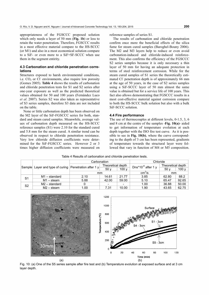
4.4 Fire performance The use of thermocouples at different levels, 0-1.5, 3, 6 and 8 cm at the centre of the samples -Fig. 10(a)- aided to get information of temperature evolution at each depth together with the ISO fire test curve. As it is pos-sible to see in Fig. 10(b), where the curve correspond-ing to the depth of 3 cm has been represented, gradients of temperature towards the structural layer were fol-lowed that vary in function of M4 or M5 composition.
Table 4 Results of carbonation and chloride penetration tests.
Carbonation Chloride Theoretical depth Theoretical depthPenetration after 1 y 50 y 100 y Dns*10-8 after 1 y 50 y 100 ySample Layer and type of curing
mm cm2/s mm M1 – standard 2.10 14.61 21.77 3.85 62.80 88.2 S1 M1 – steam 5.88 42.00 59.00 5.10 65.47 92.65M2 – standard 0 - - 1.00 36.88 50.00S2 M2 – steam 1.00 7.31 10.00 1.90 43.65 62.75
(a) (b) Fig. 10: (a) One of the S5 series sample after fire test and (b) Temperature evolution at exposed surface and at 3 cm layer depth.

O. Río, V. D. Nguyen and K. Nguyen / Journal of Advanced Concrete Technology Vol. 13, 193-204, 2015 201
The use of PPF as component of the M4 layer of the S4 series, showed a clear contribution to delay the increase of heat. As it is possible to see while temperatures over 550ºC were reached for the S1 samples at 30 mm depth, for the S4 at the same depth (or where the transition zone is located) temperatures were of 500ºC. Neverthe-less, the use of LWA+SF in the M5 layer of S5 series maintained in 30% lower the temperature at the same depth (interface) than that without M5 layer (S1 series) as shown in Fig. 10. Results also shown what was re-ported on the literature that is, a material with higher porosity and less strength performs better when exposed to fire (Kodur and Phan 2007; Alonso et al. 2011). It is noteworthy to say that, none of the samples, after fire exposure, have presented any crack or defect at inter-layer level. Moreover, no spalling was observed either for the PPF-SCCC (without LF powder addition) or in the LWA+SF-SCCC (with LF powder addition). Al-though, limestone filler particles can play an important role in producing spalling as it referred by different au-thors (Böstrom 2002; Bakhtiyari et al. 2010) results showed that this effect can be reduce when both LWA as perlite or vermiculite are used.
Therefore, the use of a thin layer designed by its composition and proportions to have higher porosity, less compressive strength (M4) and also in one of the cases aggregates with improved capabilities against fires (M5) improves the HS-SCCC capabilities played a role as a barrier which retarded the penetration of heat and the reaching of critical temperatures at certain depths. Moreover, the good interface between layers in the S4 and S5 series made FGSCCC a most attractive solution as no adhesive failure during fire test is observed then it is possible to improve fire capabilities under fire with-out reducing the needed structural strength of the ele-ment given by the HS-SCCC layer.
4.5 Evaluation of TBM effects by means of com-pressive tests. Layering method is considered sometimes insufficient for producing FGM (Ruys et al. 2001) because it leads to the formation of sharp interfaces between layers caus-ing the section fails by delamination instead of having a cohesive failure as it occurs with sections built with the same material in its entirety. Specimens of all series
were tested under uniaxial distributed compressive load up to failure as it was described in 3.4.5. Some of specimen of series S4 and S5 were tested after fire test also. Results of ultimate compressive strength are these presented on Table 5. It is noteworthy to emphasize that the values obtained follow the same trend than those of individual characterization being higher for the FGSCCCs designed for being durables and the opposite for those designed for performing better under fire. Moreover the values obtained for the FGSCCC samples were always closer to those of the individual material with higher strength. For example S2 and S3 strengths are similar to that of the material with higher nominal strength, in this case M2 or M3 (see Table 2). This also occurs in the case of samples S4 and S5, for that case the values of strength are close to that of M1 (see Table 2). Thus, although the S4 and S5 functionally graded materials result better under fire due to the protective effect of the layers M4 and M5, they keep an out-standing structural behaviour also after a fire event due to the HS-SCCC (M1 layer) is protected.
Regarding the type of failures, it is possible to men-tion that contrary to the S1 or S2 samples (HS-SCCC and SiFFGSCCC sample), which presented pyramidal failure shapes as the one shown in Fig. 11a, the remain-ing series have a combined type of failure as shown in Fig. 11b and 11c.
As it is shown in Fig. 11(b) layer containing fibres (M3) have a different failure than those without (M1). Although, the M1 layer failure is a pyramidal one, this effect only affect the area of the layer, which is most far from of the interlayer. It is remarkable to say that also the failure occurs when the material with a nominal higher strength fails.
Table 5 Average results of compression test performed on three identical samples.
Series Compressive strength (MPa) S1 69.3 S2 87.7 S3 86.1 S4 65.5
S4 (after fire test) 50.5 S5 58.8
S5 (after fire test) 51.9
(a) (b) (c)
Fig. 11 Type of failure (a) series S1 (b) series S3 and (c) series S4 after fire.

O. Río, V. D. Nguyen and K. Nguyen / Journal of Advanced Concrete Technology Vol. 13, 193-204, 2015 202
Lastly, failures of some samples of series S4 and S5, after being exposed to fire, were similar to this shown in Fig. 11(c). This anomalous failure showed by some of the samples demonstrates that the fire affected the struc-tural material of the samples (M1) in some way. Never-theless, also for these cases the mechanical strengths were quite similar to those that exhibited in compliance failures of the structural layer (similar to that of material M1 in Fig. 11 b).
It is noteworthy to emphasize that the interlayer bond in all cases remained unbroken (also for those samples tested after fire tests) and the elements show a cohesive (monolithic) failure which confirms that the multilayer FGSCCC as designed can be classified as a FGM. It was also possible to see that the use of steel fibres as part of the outer and inner layers of the segment should be a contribution in decreasing fails due to TBM effects.
4.6 Cost assessment. Through the different testing, FGSCCC samples have proven to exhibit a life expectancy in excess of 100 years and less prone to fire events. From this point of view, FGSCCC and multifunctional solutions like those proposed by some authors (Han et al. 2005; Otremba et al. 2009; Caratelli et al 2011) are similar in that they both are technologies with improved service life costs. Moreover both concrete solutions can result in a smaller tunnel profile, which allows for a smaller bore resulting in several production advantages; but these are where the similarities end. In contrast to present monolithic cast multifunctional segments, FGSCCC exhibits an optimised sectional material arrangement which in turn allows producing a value-added concrete segment mate-rial. . Even more if these are made with vibrated con-crete. FGSCCC like other SCCC solutions involves a reduction in production costs but can significantly re-duce the raw material costs too. Taking into account the comparative costs included in Table 2 and the solution proposed in Fig. 1 as the basis for the cost calculation the following results can be derived. FGSCCC, also when considering the one involving the most costly raw materials (M3-M1-M5) both using SF in their composi-tions as well as SiF (outer layer) and special aggregates (inner layer), has approximately 3 times less cost than a M3 monolithic solution. Even though for this last case a reduction of 15% in section was considered. On the other hand FGSCCC is only 1.3 times higher in raw material costs than a M1 monolithic solution. But this is almost nothing if it is also considered that the FGSCCC solution has more than 50% of service life and also do not need to be additionally protected against fire. Placement of this protective fire-resistant layer not only involves the need of more material but also an addi-tional process (shotcrete, barrier palcements, etc.). 5. Conclusions As concluding remarks of this work, which presents a new way of producing a layered-FGCCC, named as
FGSCCC, for developing most sustainable concrete solutions for tunnel segments, the following can be de-rived: • The concept was successfully examined for four
types of fire-resistant or water-tightness SCCC mixes which were combined with a strength class usual in tunnels HS-SCCC. This was done for appropriate tai-loring the differentiated mechanical and inner or outer tunnel actions along the section (S2-S5). No signifi-cant differences regarding size of interlayer among the different mix combinations were observed, as all met the designed interlayers’ depth which was in the range 2-4 mm. Moreover, no failures were observed at interlayer level either after sample preparation or after different tests were applied.
• The use of an external modified SCCC, using as part of composition either LWA+SF or PPF improves the fire resistance of the HS-SCCC solution. Both differ-entiated compositions of the external layers influ-ences on the delay of heat propagation and reduce spalling significantly. Differences also were observed between the PPF-SCCC solution and the LWA+SF solution: o The use of thermal aggregates results in a more ef-
ficient measure for retards the passage of the ex-cessive temperature even in presence of SF.
o From a mechanical point of view no significant re-ductions in terms of compressive strength between S4 and S5 samples compare to the HS_SCCC sam-ples, prior to be tested to fire, were observed; in-stead of the LWA+SF-SCCC had a nominal strength significant lowering compared with the PPF-SCCC. Reductions of compressive strength of S5 sample exposed to fire were lower than those of S4. This means that S5 has a better isolation capac-ity. Moreover S5 results tougher due to the SF.
• The use of an external modified SCCC, using as part of composition either SiF or SiF+SF improves the water-tightness of the HS-SCCC. Both differentiated compositions of these water-tightness external layers contribute to delay the damage due to steel rein-forcement corrosion in more than 50y. No differences were observed between them in this sense: o The addition of SiF especially when steam curing
improves the S2 and S3 samples service life capa-bilities. Both, the SiF and the steam curing strongly reduce pore size of the HS-SCCC.
o .From a mechanical point of view a significant in-creasing in terms of compressive mechanical strength was observed between S4 and S5 samples when compare to HS-SCCC, being for both quite similar. Moreover the S3 samples present a most tough behaviour due to the SF of the M3 layer.
• If the S3-S5 is merged in one for being use in a tunnel segment of 50cm thickness they will result in an ini-tial concrete material cost 1.3 times higher than one made of HS_SCCC material only. Nevertheless, it has on contrary a durability equal to or even more higher

O. Río, V. D. Nguyen and K. Nguyen / Journal of Advanced Concrete Technology Vol. 13, 193-204, 2015 203
than (if fire comes also into consideration) one cast with a SiF+SF-SCCC material which cost results ap-proximately 3 times higher than this FGSCC solution also for a thickness section reduction. Moreover in terms of life extension S3-S5 results in a 50% more than when using S1.
Aknowledgements The authors want to express their thanks to other CSIC collaborators involved in part of the experimental pro-gramme. This work was partially founded by the JAE program financed by the EU Social Fund, which support the PhD works of V.D. Nguyen and the “Ministry of Economy and Competitiveness” through the project BIA2013-48480-C2-1&2-R. The authors are also grate-ful to the reviewers’ comprehensive comments, which helped them to improve the manuscript, particularly with respect to the potential of the current solution. References Aitcin, P., (2011). “High performance concrete.” CRC
Press. 624 ps. Alonso, M. C., Garcia, J. L., Robles, M. and Fernández
Luco, L., (2012). “Influence of the microstructural changes on the durability of precast products due to heat curing.” In: G. Ye, K.V. Breugel, W. Sun, and C. Miao Eds. Proceeding of Second International Conference on Microstructural-related Durability of Cementitious Composites, Amsterdam 11-13 April 2012, RILEM PRO 83, 151-156.
Alonso, M. C., Rio, O., Rodríguez, C. and Nguyen, V. D., (2011) “Avoiding spalling of precast HPC & UHPC elements by using a novel layered concept.” In: E. A. B. Koenders and F. Dehn, Eds. Proceeding of Second International RILEM Workshop in Concrete spalling due to fire exposure, Delft 5-7 October2011. RILEM Pro 80, 393-400.
Ashrafi, H. R. and Ramezanianpour, A. A., (2007). “Service life prediction of silica fume concretes.” International Journal of Civil Eng., 5, 182-197.
Baoguo, M., Dinghua, Z. and Li, X., (2009). “Manu-facturing technique and performance of functionally graded concrete segment in shield tunnel.” Frontiers of Architecture and Civil Engineering in China, 3(1), 101-104.
Baroghel-Bouny, V., (2006). “Durability indicators: Relevant tools for performance-based evaluation and multi-level prediction of RC durability.” In: V Baroghel-Bouny, C. Andrade, R Torrent and K Scrivener Eds. Proceeding of International RILEM Workshop on Performance Based Evaluation and Indicators for Concrete Durability, 19-21 March, 2006, Madrid, Spain, 3-30.
Bakhtiyari, S., Allahverdi, A. and Rais, Ghasemi, M., (2010). “The influence of permanent expanded poly-styrene formwork on fire resistant of self-compacting and normal vibrated concrete.” Asian Journal of Cevil Eng., 12, 353-374.
Bever, M. B. and Duwez, P. E., (1972) “Gradients in composite materials.” Materials Science Engineering, 10(1), 1-4.
Bosch, C., Río, O. and Fernandez-Luco, L., (2010). “Fire resistance segment for tunnels and manufactur-ing process.” Spanish Patent ES2326936.
Böstrom, L., (2002). “The performance of some Self-Compacting Concretes when exposed to fire.” In. SP report 2002:23, SP Technical Research Institute.
Browers, H. J. H. and Radix, H. J., (2005). “Self-compacting concrete theoretical and experimental study.” Cement and Concrete Research, 35, 2116-36.
Caratelli, A., Meda, A., Rinaldi, Z. and Romualdi, P., (2011). “Structural behaviour of precast tunnel segments in fiber reinforced concrete.” Tunnelling and Underground Space Technology, 26(2), 284-291.
De Schutter, G., (2011) “Self-compacting concrete after two decades of research and practice.” In: New Zealand Concrete Society Eds. Proceeding of 9th Symposium on High Performance Concrete: Design, Verification and Utilization, Rotorua 9-11 August 2011, 838-851.
Dias, C. M. R., Savastano, H. and John, V. M., (2010) “Exploring the potential of functionally graded mate-rials concept for the development of fiber cement.” Construction and Building Materials, 24(2), 140-146.
Fernández-Luco, L., Río, O. and Castillo, A., (2007). “Performance-based proposal for precast self-com-pacting concrete (SCC) segments [CD-ROM]”. In: J. Eberhardsteiner, G. Beer, C. Hellmich, H. A. Mang, G. Meschke, and W. Schubert Eds. Proceeding of ECCOMAS Thematic conference on Computational Methods in Tunneling (EURO: TUN 2007). Vienna-Austria. 27-29 August 2007.
Franzén, T. and Celestino, T. B., (2002) .“Lining of tunnels under groundwater pressure.” In: Proceeding of International Tunneling Association Conference, Sydney March 2002, 1, 481-487.
Gall, V. and Soe, Z., (2011). “Quality and risk manage-ment considerations for very shallow soft ground conventional tunnelling in urban settings. [CD-ROM]” In: ITA Eds. Proceedings of World Tunnel Congress and 37th ITA General Assembly, Helsinki, May 20-26, 2011.
Ghezal, A. and Khayat, K. H., (2002). “Optimizing self-consolidating concrete with limestone filler by using statistical factorial design methods.” ACI Materials Journal, 99(3), 264-272.
Gomes, A. R. A., (2005). “Waterproofing and drainage systems for transport tunnels-A review of current practices.” Felsbau-Rock and Soil Engineering, 3, 46-49.
Han, C. G., Hwang, Y. S., Yang, S. H. and Gowripalan, N., (2005) “Performance of spalling resistance of high performance concrete with polypropylene fiber contents and lateral confinement.” Cement and Concrete Research, 35(9), 1747-1753.
Ho, D. W. S. M., Sheinn, A. M. M. and Tam, C. T.,

O. Río, V. D. Nguyen and K. Nguyen / Journal of Advanced Concrete Technology Vol. 13, 193-204, 2015 204
(2004). “The sandwich concept of construction with SCC.” Cement and Concrete Research, 31(9), 1377-1381.
Kim, J. H. J., Lima, Y. M., Won, J. P. and Park, H. G., (2010). “Fire resistant behaviour of newly developed bottom-ash-based cementitious coating applied con-crete tunnel lining under RABT fire loading.” Const-ruction and Building Materials, 24(10), 1984-1994.
Kodur, V. K. R. and Phan, L., (2007). “Critical factors governing the fire performance of high strength concrete systems.” Fire Safety Journal, 42(6-7), 482-488.
Kumar, R. and Bhattacharjee, B. (2003). “Porosity, pore size distribution and in situ strength of concrete.” Cement and Concrete Research, 33(1), 155-164.
Maalej, M., Ahmed, S. F. U. and Paramasivam, P., (2003). “Corrosion durability and structural response of functionally-graded concrete beams.” Journal of Advanced Concrete Technology, 1(3), 307-316.
Mosley, B., Bungey, J. and Hulse, R., (2007). “Reinforced concrete design to Eurocode 2.” 6th New York, Palgrave MC. Ed.
Nokken, M. R. and Hooton, R. D. (2007). “Using pore parameters to estimate permeability or conductivity of concrete.” Materials and Structures, 41(1), 1-16.
Otremba, H. and Kessler, D., (2009). “High Performance and ultra-high performance concrete segments-development and testing.” In: G. Beer, Eds. Technology Innovation in Underground Construction.
London: CRC Press Taylor & Francis, 423-444. Río, O. (2009). “Pre-cast cement-based hybrid section
and method for the production thereof”, Spanish Patent ES 2347035 B1, Filed Patent Number: P 200930081, International Reference: WO 2010122201 A2, In Spanish.
Río, O., Nguyen, V. D. and Turrillas X. (2013). “Functionally-graded self-compacting cement composites [CD-ROM]”, In: S.P. Shah and K. Wang Eds. Proceeding of 5th North American conference on the design and use of self-compacting concrete, Chicago-USA, 12-15 May 2013.
Ruys, A. J., Popov, E. B., Sun, D., Russel, J. J. and Murray, C. C. J., (2001). “Functionally graded electrical/Thermal ceramic systems.” Journal of European Ceramic Society, 21(10-11), 2025-2029.
Shen, B., Hubler, M., Paulino, G. H. and Struble. L. (2008). “Functionally-graded fiber-reinforced cement composite: Processing, microstructure, and proper-ties.” Cement Concrete Composite, 30(8), 663-673.
Wen, X., Baoguo, M., Gan, W. and Xian, Z., (2010). “Design and research on gradient structure concrete based on volumetric stabilization.” ACI Materials Journal, 107(6), 611-616.
Ye, G., Liu, X., de Schutter, G., Taerwe, L. and Vandevelde, V., (2007). “Phase distribution and microstructural change of self-compacting cement paste at elevated temperature.” Cement and Concrete Research, 37, 978-987.
Related Documents


