Issue No. 230 Summer 2011

Welcome message from author
This document is posted to help you gain knowledge. Please leave a comment to let me know what you think about it! Share it to your friends and learn new things together.
Transcript
Issue No. 230 Summer 2011
CHANGING THE STANDARDS
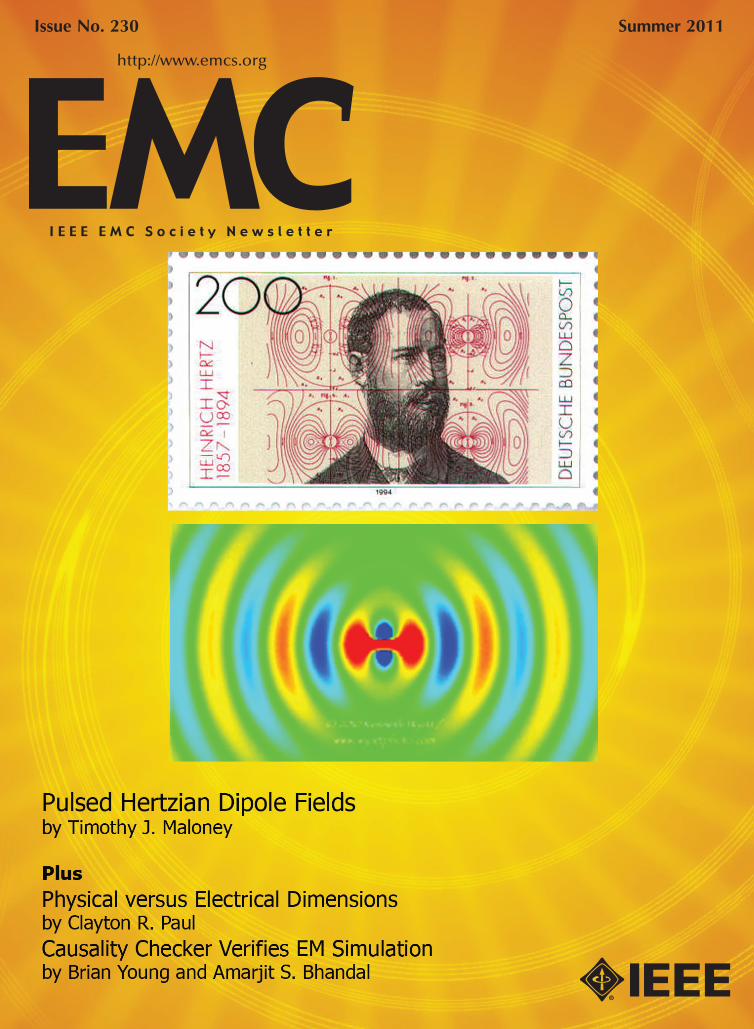
Y Get equipped with leading edge EM technology. CST’s tools enable you to characterize, design and optimize electro-magnetic devices all before going into the lab or measurement chamber. This can help save substantial costs especially for new or cutting edge products, and also reduce design risk and improve overall performance and profitability.
Involved in emc/emi analysis? You can read about how CST technology is used for EMC/EMI analysis at www.cst.com/emc. If you’re more interested in microwave components or signal integrity analysis, we’ve a wide range of worked application examples live on our website at www.cst.com/apps.
Now even more choice for EMC/EMI simula-tion. The extensive range of tools integrated in CST STUDIO SUITE enables numerous applications to be analyzed without leaving the familiar CST design environment. This complete technology approach enables unprecedented simulation reliability and additional security through cross verification.
Y Learn more about CST STUDIO SUITE. Register for CST Leading Technology Webinars on EMC/EMI at www.cst.com/emc-webinar.
Explore the EM simulation universe
Emissions from server housing
CST of America®, Inc. | To request literature (508) 665 4400 | www.cst.com
3
FIELD OF INTEREST The Field of Interest of the Electromagnetic Compatibility (EMC) Society involves engineering related to the electromagnetic environmental effects of systems to be compatible with itself and their intended operating environment. This includes: standards, measurement techniques and test procedures, instrumentation, equipment and systems characteristics, interference control tech-niques and components, education, computational analysis, and spectrum management, along with scientific, technical, industrial, professional or other activities that contribute to this field.
Letter from the Editor Newsletter StaffEditor-in-ChiefJanet Nichols O’NeilETS-Lindgren1301 Arrow Point DriveCedar Park, TX 78613425.868.2558e-mail: [email protected]
Technical EditorKye Yak SeeDivision of Circuits & SystemsNanyang Technological UniversityS1-B1c-100, 50 Nanyang AvenueSingapore 639798+1 (65) 6790-6351fax: +1 (65) 67912687e-mail: [email protected]
IEEE EMC SOCIETY NEWSLETTER (ISSN 1089-0785) is published quar-terly by the Electromagnetic Compatibility Society of the Institute of Electri-cal and Electronic Engineers, Inc., 3 Park Avenue, 17th Floor, New York, NY 10016-5997. One dollar ($1.00 USD) per member per year (included in the Society fee) for each member of the EMC Society. Periodicals postage paid at New York, NY and additional mailing offices. This newsletter is printed in the USA. Postmaster: Send address changes to IEEE EMC Society Newsletter to 445 Hoes Lane, Piscataway, NJ 08854.
© 2011 IEEE. Permission to copy without fee all or part of any material without a copyright notice is granted provided that the copies are not made or distributed for direct commercial advantage, and the title of the publica-tion and its date appear on each copy. To copy material with a copyright notice requires specific permission. Please direct all inquiries or requests to IEEE Copyrights Office.
ISSN 1089-0785
ABSTRACTSProfessor Osamu FujiwaraDept. of Elec. & Comp. EngineeringNagoya Institute of TechnologyGokiso-cho, Showa-ku, Nagoya 466-8555 Japan+81.52.735.5421fax: +81.52.735.5442e-mail: [email protected] REVIEWSAntonio OrlandiUAq EMC Laboratory, EE Dept.University of L’AquilaI-67040 Poggio di RoioL’Aquila ITALY+39-0862-344779 (211)fax: +39-0862-344527e-mail: [email protected] CHATTERTodd RobinsonCKC Laboratories, Inc.5473A Clouds RestMariposa, CA 95338209.966.5240 x207fax: 209.742.6133e-mail: [email protected] CAREERSDonald N. Heirman143 Jumping Brook RoadLincroft, NJ 07738-1442732.741.7723fax: 732.530.5695e-mail: [email protected] DESIGN TIPSBruce ArchambeaultIBM, P. O. Box 12195Department 18DA B306Research Triangle Park, NC 22709919.486.0120e-mail: [email protected] PHOTO/DESIGN © Kenneth Wyattwww.wyattphoto.com
EMC PERSONALITY PROFILEWilliam G. DuffSENTEL, 7601 South Valley DriveFairfax Station, VA 22039e-mail: [email protected]
Frank SabathWIS, HumboldstrasseD-29633 Munster, Germany+49.4172.988083Fax: +49.4172.988083e-mail: [email protected]
EMC STANDARDS ACTIVITIESDonald N. Heirman143 Jumping Brook RoadLincroft, NJ 07738-1442732.741.7723fax: 732.530.5695e-mail: [email protected]
EMCS BoD ACTIVITIESJanet Nichols O’NeilETS-Lindgren1301 Arrow Point DriveCedar Park, TX 78613425.868.2558e-mail: [email protected]
EMCS EDUCATION COMMITTEETom Jerse, ProfessorThe Citadel – Dept. of ECE171 Moultrie StreetCharleston, SC 29409843.953.7499e-mail: [email protected]
EMC SOCIETY HISTORY & 50th ANNIVERSARYDan HoolihanHoolihan EMC ConsultingP. O. Box 367Lindstrom, MN 55045651.213.0966fax: 651.213.0977e-mail: [email protected]
Associate Editors
Susan E. SchneidermanBusiness Development Manager, IEEE MagazinesIEEE Media445 Hoes Lane,Piscataway NJ 08854 USATel: +1-732-562-3946; Fax: +1-732-981-1855www.ieee.org/ieeemedia [email protected]
Advertising
33IEEE prohibits discrimination, harassment, and bullying. For more information,visit http://www.ieee.org/web/aboutus/whatis/policies/p9-26.html.
continued on page 75
IEEE EMC Society Newsletter Publication Schedule Publication Editorial AdvertisingDates Deadlines DeadlinesSummer July 1 July 12Fall October 1 October 11Winter January 1 January 14Spring April 1 April 11
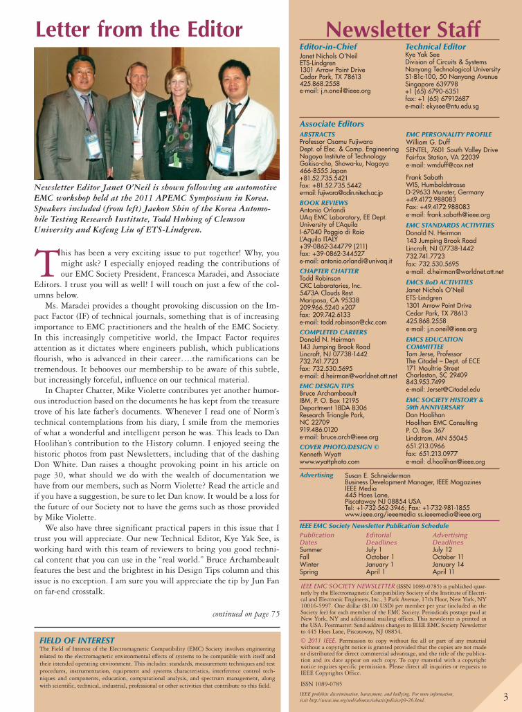
Newsletter Editor Janet O’Neil is shown following an automotive EMC workshop held at the 2011 APEMC Symposium in Korea. Speakers included (from left) Jaekon Shin of the Korea Automo-bile Testing Research Institute, Todd Hubing of Clemson University and Kefeng Liu of ETS-Lindgren.
This has been a very exciting issue to put together! Why, you might ask? I especially enjoyed reading the contributions of our EMC Society President, Francesca Maradei, and Associate
Editors. I trust you will as well! I will touch on just a few of the col-umns below.
Ms. Maradei provides a thought provoking discussion on the Im-pact Factor (IF) of technical journals, something that is of increasing importance to EMC practitioners and the health of the EMC Society. In this increasingly competitive world, the Impact Factor requires attention as it dictates where engineers publish, which publications flourish, who is advanced in their career….the ramifications can be tremendous. It behooves our membership to be aware of this subtle, but increasingly forceful, influence on our technical material.
In Chapter Chatter, Mike Violette contributes yet another humor-ous introduction based on the documents he has kept from the treasure trove of his late father’s documents. Whenever I read one of Norm’s technical contemplations from his diary, I smile from the memories of what a wonderful and intelligent person he was. This leads to Dan Hoolihan’s contribution to the History column. I enjoyed seeing the historic photos from past Newsletters, including that of the dashing Don White. Dan raises a thought provoking point in his article on page 30, what should we do with the wealth of documentation we have from our members, such as Norm Violette? Read the article and if you have a suggestion, be sure to let Dan know. It would be a loss for the future of our Society not to have the gems such as those provided by Mike Violette.
We also have three significant practical papers in this issue that I trust you will appreciate. Our new Technical Editor, Kye Yak See, is working hard with this team of reviewers to bring you good techni-cal content that you can use in the “real world.” Bruce Archambeault features the best and the brightest in his Design Tips column and this issue is no exception. I am sure you will appreciate the tip by Jun Fan on far-end crosstalk.
4
President’s MessageFrancesca Maradei, President, IEEE EMC Society
4
By the time you read this message, the annual IEEE EMC Sym-posium that was held in Long Beach (CA) this year will be history. In the meantime, while waiting for the usual detailed report on the exciting symposium week to come in the Fall 2011 issue of this Newsletter, I wish to cover in this message a few “hot topics”.
Forthcoming Launch in 2012 of the IEEE EMC Society MagazineAs already announced in my President’s message that appeared in the Fall 2010 issue, at the beginning of 2012 the transition of the EMC Newsletter into the EMC Magazine will be effec-tive. The EMC Society Newsletter has been looking like a magazine for many years, therefore, under the aesthetical viewpoint, the magazine will not look much different from what we are used to right now. In any case, the transition is a kind of upgrade for our Newsletter. If we look at the IEEE ranking of periodicals, a Magazine is more valuable than a Newsletter. The Magazine content will be included in the IEEE Xplore digital library and indexed in the official Journal Citation Report. This is the major novelty of becoming a magazine and it will give a much wider exposure to the pub-lished technical papers and other content. An increased num-ber of practical papers per issue is also planned. I would like to take this opportunity to solicit authors to take into serious consideration the possibility of submitting the outcome of their practical research and design tips for publication in the forthcoming EMC Magazine. In closing, I wish to bring to your attention the new logo of the IEEE EMC magazine so that you can start to become familiar with it.
Impact Factor (IF) of JournalsThe Impact Factor (IF) is increasingly popular as an index used for evaluating and ranking journals. Even if almost everyone has heard about the IF, I am not so sure how many of you are really familiar with it and its increasing use. For this reason, I’ll go through a brief historical background.
The IF is a measure reflecting the average number of citations of articles published in science and social science journals and was developed to compare journals regardless of their size. It was devised in the 60s by Eugene Garfield, the founder of the Institute for Scien-tific Information (ISI), now part of Thomson Reuters. Impact factors are calculated yearly for those journals that are indexed in Thomson Reuter’s Journal Citation Report (JCR).
DefinitionThe IF is a measure of the frequency with which the “average article” in a journal has been cited in a particular year or period. The annual JCR impact factor is a ratio between citations and recent citable items published during a rolling two year win-dow. Thus, the IF of a journal is calculated by dividing the number of current year citations by the source items published in that journal during the previous two years:
IF 5 c Number of Citations 1NoC 2Number of Articles Published 1NoAP 2 d during a rolling
two year window
As an example, the 2010 IF is calculated assuming:NoC 5 number of citations in 2010 of papers published in
2008–2009NoAP 5 number of the citable items in 2008–2009
Journals with High IF Published Articles That are Cited More Often Than Journals with Lower IfIf citation numbers are taken as a measure of quality or impor-tance, then these journals are ranked higher by this measure.
Letter from the Editor . . . . . . . . . . . . . . . . . . . . . 3
President’s Message . . . . . . . . . . . . . . . . . . . . . . . 4
Chapter Chatter . . . . . . . . . . . . . . . . . . . . . . . . . 8
Completed Careers . . . . . . . . . . . . . . . . . . . . . . 18
EMC Personality Profile . . . . . . . . . . . . . . . . . . 22
EMC Society History. . . . . . . . . . . . . . . . . . . . . 24
EMC Society Newsletter Articles – 50–25–10 Years Ago . . . . . . . . . . . 24
Quasies and Peaks—The Precursor to the EMC Society Newsletter May 1955 . . . 27
Digitizing Historical EMC Society Records . . . . . . . . . . . . . . . . . . . 30
Practical Papers, Articles and Application Notes . . . . . . . . . . . . . . . . . . 34
Easy Access to Pulsed Hertzian Dipole Fields Through Pole-Zero Treatment . . . . . . . . . . . . 34
Physical Dimensions vs Electrical Dimensions . . . . . . . . . . . . . . . . . . . . . . . . . . 43
A Simple Causality Checker and Its Use in Verifying, Enhancing, and Depopulating Tabulated Data from Electromagnetic Simulation . . . . . . . . . . . . 49
Design Tips. . . . . . . . . . . . . . . . . . . . . . . . . . . . 55
Far-End Crosstalk . . . . . . . . . . . . . . . . . . . . . . . 55
EMC Standards Activity . . . . . . . . . . . . . . . . . . 58
The 2011 Asia-Pacific EMC
Symposium in Korea . . . . . . . . . . . . . . . . . . . 61
Report on IEEE Membership
Activity at the 2011 APEMC Symposium . . . 63
EMCABS. . . . . . . . . . . . . . . . . . . . . . . . . . . . . . 66
Bylaws Changes. . . . . . . . . . . . . . . . . . . . . . . . . 70
Publication of Amendments
to EMC Society Constitution and Bylaws . . . . 70
The Secretary’s Pavane. . . . . . . . . . . . . . . . . . . . 73
Books Wanted. . . . . . . . . . . . . . . . . . . . . . . . . . 75
Calendar . . . . . . . . . . . . . . . . . . . . . . . . . . . . . . 77

Whether you choose one of our standard test systems – or have AR build a system to your specs – you’ll be amazed athow easy, accurate, efficient, and affordable testing can be. Everything you need is right at your fingertips. It all works together perfectly,because everything has been carefully selected and assembled by AR engineers, using the most dependable and most innovativeequipment on the market today.
Why An AR System Is The Smart Way To Test:• No company has more experience and expertise inEMC test equipment than AR
• Reduced Test Time – get products to market faster• Increased Accuracy• Lower Risk
AR can deliver a solution that integrates all your testing needs: radiated immunity, conducted immunity,conducted emissions, radiated emissions, electrostatic discharge, lightning simulation … whatever you need.
We have the expertise and experience to supply turn-key and fully automated systems needed to test variousstandards including IEC 61000, MIL-STD 461 and 464, DO-160, wireless, automotive, HIRF and HERO.
To learn more, visit us at www.arworld.us or for technical support call 800-933-8181.Visit http://goo.gl /GsBln to find out more.
• Performance Guarantee – AR manufactures the majority of the systemcomponents allowing us to match and guarantee their performance
• Everything is fully tested before being shipped• Single source for support & service• More Compact & Portable – everything can be on one platform.
Solve Your Systems Needs
Fully Integrated Test SystemsSolutions For Any Application from DC to 50 GHz
rf/microwave instrumentationOther ar divisions: modular rf • receiver systems • ar europeUSA 215-723-8181. For an applications engineer, call 800-933-8181.InEurope, call arUnitedKingdom441-908-282766•ar France 33-1-47-91-75-30• emvGmbH89-614-1710•arBenelux 31-172-423-000
ISO 9001:2008Certified
Copyright © 2011 AR. The orange stripe on AR products is Reg. U.S. Pat. & TM. Off.
6
Criticisms of IFThe Impact Factor is historically the most diffused biblio-graphic index since it is simple to compute and understand. It has, however, some drawbacks, including:• Two-year window (short snapshot) - Using a time window of
two years to account for citations may not be enough in some domains. In fact, some disciplines use older material more or take time to cite new research. As a consequence of this, the IF may fluctuate significantly from year to year. To overcome this problem, JCR now also includes the 5-year data.
• Artificial inflation – The IF is prone to manipulation to achieve artificial inflation. Some editors and journals request authors to cite recently published papers in the same journal before providing the final acceptance, or encourage self-cita-tions. These unethical practices are strongly affecting the fair-ness and credibility of the IF, and should be prohibited by serious journals. In addition, there are a number of issues strongly affecting
the IF, including the number of journals published in a disci-pline, the ISI coverage, the language (biased toward English-language journals), publication type (specialty Journals have lower IF), journal size, and self citations.
Applications of IFPerhaps the most important and recent use of impact factor is in the process of academic evaluation. For some researchers, moni-toring citation statistics and journal impact factors is an intense-ly serious business. In many European and Asian universities, for example, the IFs of the journals in which scientists publish their work are tallied, and the data plugged into formulae that directly influence a scientist’s career advancement and the fund-ing given to individual departments and research groups. Worldwide, citation statistics are increasingly being used as a convenient metric to assess the quality of scientists’ work.
In summary, the several applications of journal impact fac-tors include:• Judge publication quality and prestige• Evaluate the scholarly merit of a journal • Rank journals within a discipline• Help authors decide where to publish their article for maxi-
mum impact• Evaluation of scholarly research and individual performance
for purposes of promotion/tenure/grants, and funding• Evaluation of departments, institutions, and nations• Journal assessment/marketing by publishers• Evaluation source for librarians during journal cancellations
or new purchasesConsidering the mentioned criticisms, the reliability of the
IF for ranking journals is quite arguable, and for this reason other bibliographic indexes (i.e., eigenfactor, SCImago Journal Rank (SJR), etc.) are being investigated. Intuitively, a “good quality index” should:• Give a result which corresponds to the technical quality of the
papers published in that journal;• Be consistent over time (it takes a long time to build the
reputation of a publication and it is reasonable to expect that a good quality index should not exhibit large fluctuations over a limited time); and
• Be immune to external manipulation (it should be very dif-ficult to artificially manipulate its value).
Even if Thomson Reuters is recommending using the IF wisely - since without an informed and careful use of the impact data, users may be tempted to jump to ill-formed conclusions - right now the increasing popularity is encouraging an extensive use of this index without addressing enough attention to its criticisms.
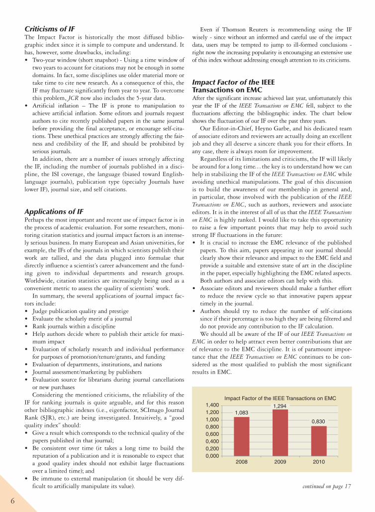
Impact Factor of the IEEE Transactions on EMCAfter the significant increase achieved last year, unfortunately this year the IF of the IEEE Transactions on EMC fell, subject to the fluctuations affecting the bibliographic index. The chart below shows the fluctuation of our IF over the past three years.
Our Editor-in-Chief, Heyno Garbe, and his dedicated team of associate editors and reviewers are actually doing an excellent job and they all deserve a sincere thank you for their efforts. In any case, there is always room for improvement.
Regardless of its limitations and criticisms, the IF will likely be around for a long timep the key is to understand how we can help in stabilizing the IF of the IEEE Transactions on EMC while avoiding unethical manipulations. The goal of this discussion is to build the awareness of our membership in general and, in particular, those involved with the publication of the IEEE Transactions on EMC, such as authors, reviewers and associate editors. It is in the interest of all of us that the IEEE Transactions on EMC is highly ranked. I would like to take this opportunity to raise a few important points that may help to avoid such strong IF fluctuations in the future: • It is crucial to increase the EMC relevance of the published
papers. To this aim, papers appearing in our journal should clearly show their relevance and impact to the EMC field and provide a suitable and extensive state of art in the discipline in the paper, especially highlighting the EMC related aspects. Both authors and associate editors can help with this.
• Associate editors and reviewers should make a further effort to reduce the review cycle so that innovative papers appear timely in the journal.
• Authors should try to reduce the number of self-citations since if their percentage is too high they are being filtered and do not provide any contribution to the IF calculation. We should all be aware of the IF of our IEEE Transactions on
EMC in order to help attract even better contributions that are of relevance to the EMC discipline. It is of paramount impor-tance that the IEEE Transactions on EMC continues to be con-sidered as the most qualified to publish the most significant results in EMC.
1,0831,294
0,830
0,0000,2000,4000,6000,8001,0001,2001,400
2008 2009 2010
Impact Factor of the IEEE Transactions on EMC
continued on page 17
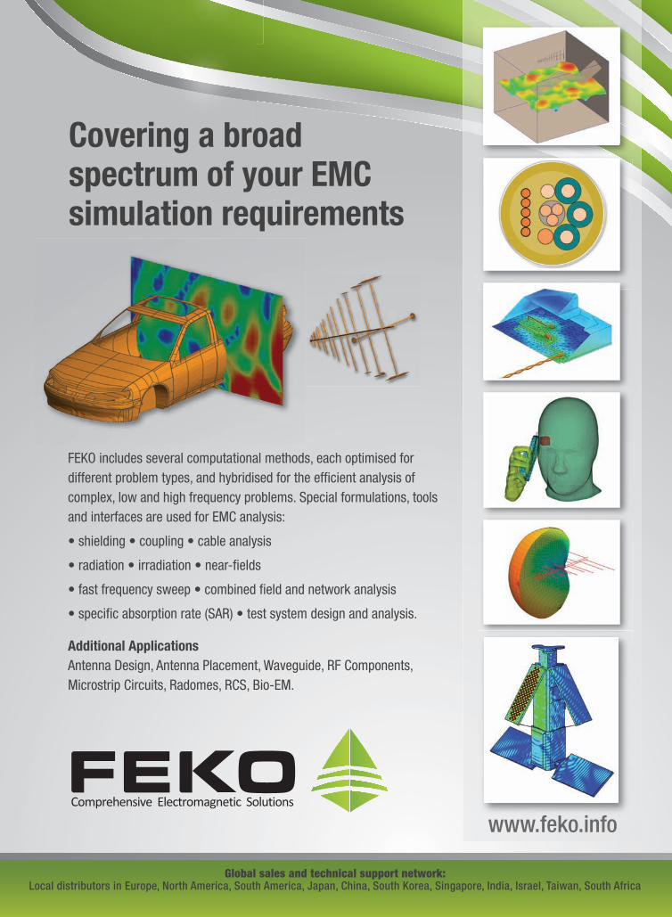
Covering a broad spectrum of your EMC simulation requirements
Global sales and technical support network:Local distributors in Europe, North America, South America, Japan, China, South Korea, Singapore, India, Israel, Taiwan, South Africa
FEKO includes several computational methods, each optimised for different problem types, and hybridised for the efficient analysis of complex, low and high frequency problems. Special formulations, tools and interfaces are used for EMC analysis:
Additional Applications
www.feko.info
8
Chapter ChatterTodd Robinson, Associate Editor
Norm’s NotebookA Transient Situation (circa 1988)By Mike Violette
common test in the EMC lab is Electrical Fast Tran-sients (EFTs). The test subjects equipment to a series of fast (,1 nanosecond rise) pulses of a 5001V to
signal and power cables. It is a good measure of the immu-nity to high-energy, short burst (high frequency) noise sources. This test simulates electrical noise generated by opening and closing of relay contacts and other transient sources.
We know from electrical theory that a current flowing through a conductor creates a magnetic field. This field rep-resents a form of “stored” energy that cannot decrease instan-taneously to zero when the current is interrupted. This is especially true in a coil or inductor, where the field concen-tration is “amplified” because of the additive effect of the number of turns in the coil. When the current is interrupted, the collapsing magnetic field acts to keep the current flow-ing. With nowhere to go, a surge voltage is produced as the current “breaks” against the open circuit. If the voltage is high enough, an arc may be produced.
From Norm’s notebook, he explored the question, “What is the peak voltage generated when the coil current is inter-rupted?” Assume a 12 VDC coil voltage and choose one:• 48V• 460V• 1200V• 4600V
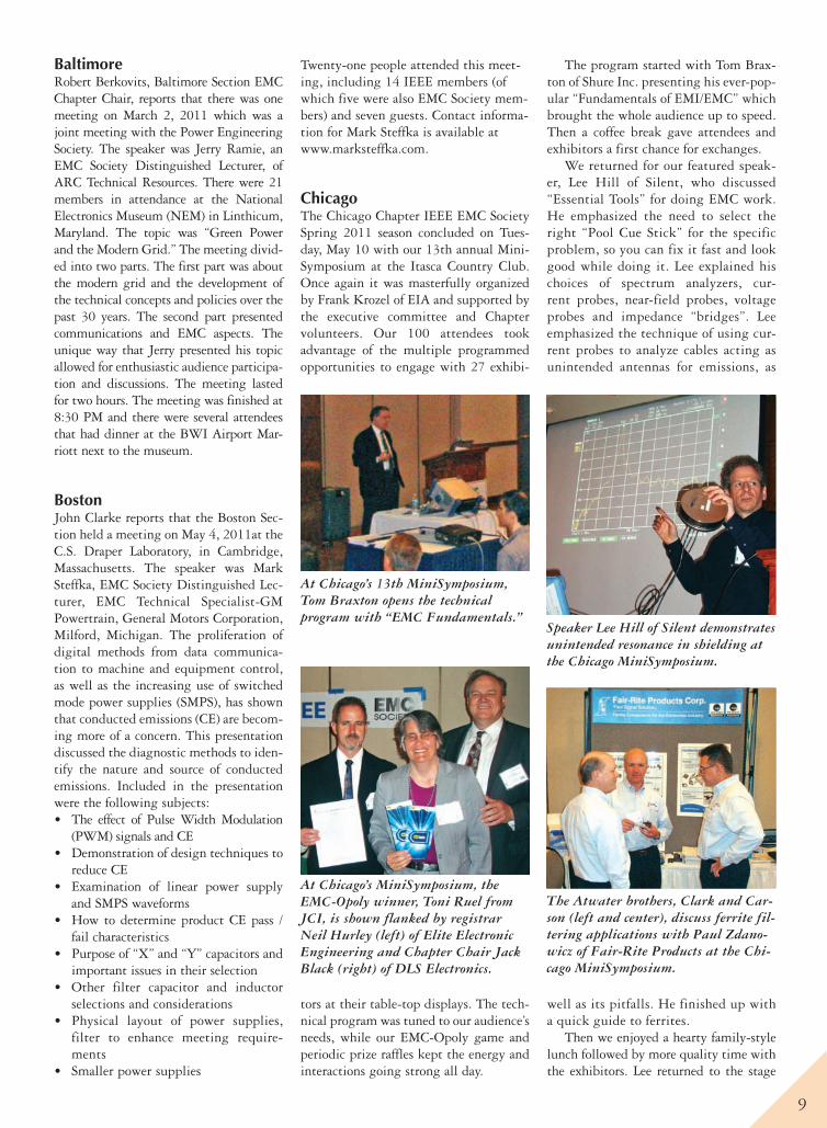
The example circuit is shown below:
The circuit shows a relay coil with inductance L and resis-tance R connected to a voltage source E through switch S. The capacitance C can be intentionally installed or it can be a para-sitic capacitance (or a combination of both). At reference time t = 0, the relay is disconnected from the source by opening S.
Initial conditions (@ t = 0): v c(0) = 2E; i(0) = I
o= E/R;
charge q(0) = −CENow, while some people pass their time doing crossword
puzzles or watching “Dancing with the Stars” or playing Angry Birds on their iPAD™, Norm liked to doodle with exponents and Green’s functions and such. (This particular pastime did not get passed along, unless it has skipped a generation.)
At any rate, the underdamped, oscillatory case is of inter-est and is set up below:
Reasonable assumptions for the values of the circuit ele-ments and initial voltage are plugged in:
E 5 12VDC; R 5 200V; C 5 50pF and L 5 200mH
And another page of dense math follows, ultimately lead-ing to the final solution shown below:
The question was: “What is the peak voltage?” Solving for the maximum of the oscillatory waveform (which occurs at about 6µs) yields the answer below:
So if you guessed – or inferred – that a 12 VDC coil could generate a peak transient of almost 400 times the initial volt-age, you guessed – or inferred – correctly.
If you are interested in the entire derivation, visit http://wll.com/inprint.html#other.
Happy arcing.
A
9
BaltimoreRobert Berkovits, Baltimore Section EMC Chapter Chair, reports that there was one meeting on March 2, 2011 which was a joint meeting with the Power Engineering Society. The speaker was Jerry Ramie, an EMC Society Distinguished Lecturer, of ARC Technical Resources. There were 21 members in attendance at the National Electronics Museum (NEM) in Linthicum, Maryland. The topic was “Green Power and the Modern Grid.” The meeting divid-ed into two parts. The first part was about the modern grid and the development of the technical concepts and policies over the past 30 years. The second part presented communications and EMC aspects. The unique way that Jerry presented his topic allowed for enthusiastic audience participa-tion and discussions. The meeting lasted for two hours. The meeting was finished at 8:30 PM and there were several attendees that had dinner at the BWI Airport Mar-riott next to the museum.
BostonJohn Clarke reports that the Boston Sec-tion held a meeting on May 4, 2011at the C.S. Draper Laboratory, in Cambridge, Massachusetts. The speaker was Mark Steffka, EMC Society Distinguished Lec-turer, EMC Technical Specialist-GM Powertrain, General Motors Corporation, Milford, Michigan. The proliferation of digital methods from data communica-tion to machine and equipment control, as well as the increasing use of switched mode power supplies (SMPS), has shown that conducted emissions (CE) are becom-ing more of a concern. This presentation discussed the diagnostic methods to iden-tify the nature and source of conducted emissions. Included in the presentation were the following subjects: • The effect of Pulse Width Modulation
(PWM) signals and CE • Demonstration of design techniques to
reduce CE • Examination of linear power supply
and SMPS waveforms • How to determine product CE pass /
fail characteristics • Purpose of “X” and “Y” capacitors and
important issues in their selection • Other filter capacitor and inductor
selections and considerations • Physical layout of power supplies,
filter to enhance meeting require-ments
• Smaller power supplies
Twenty-one people attended this meet-ing, including 14 IEEE members (of which five were also EMC Society mem-bers) and seven guests. Contact informa-tion for Mark Steffka is available at www.marksteffka.com.
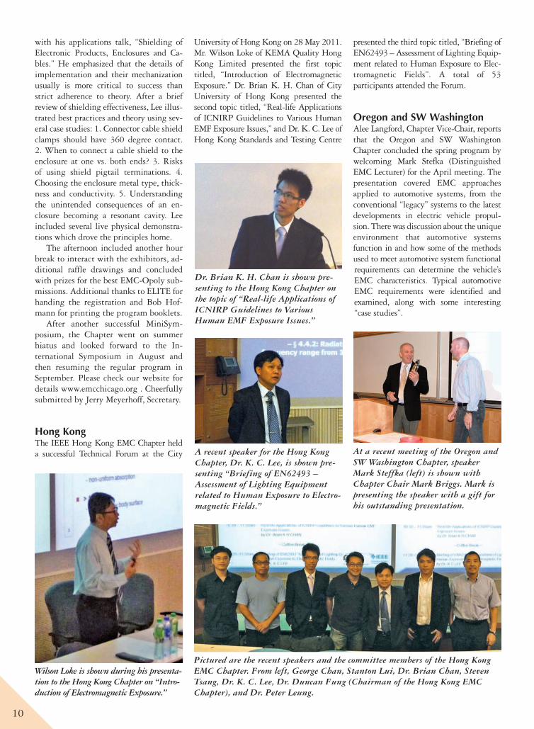
ChicagoThe Chicago Chapter IEEE EMC Society Spring 2011 season concluded on Tues-day, May 10 with our 13th annual Mini-Symposium at the Itasca Country Club. Once again it was masterfully organized by Frank Krozel of EIA and supported by the executive committee and Chapter volunteers. Our 100 attendees took advantage of the multiple programmed opportunities to engage with 27 exhibi-
tors at their table-top displays. The tech-nical program was tuned to our audience’s needs, while our EMC-Opoly game and periodic prize raffles kept the energy and interactions going strong all day.
The program started with Tom Brax-ton of Shure Inc. presenting his ever-pop-ular “Fundamentals of EMI/EMC” which brought the whole audience up to speed. Then a coffee break gave attendees and exhibitors a first chance for exchanges.
We returned for our featured speak-er, Lee Hill of Silent, who discussed “Essential Tools” for doing EMC work. He emphasized the need to select the right “Pool Cue Stick” for the specific problem, so you can fix it fast and look good while doing it. Lee explained his choices of spectrum analyzers, cur-rent probes, near-field probes, voltage probes and impedance “bridges”. Lee emphasized the technique of using cur-rent probes to analyze cables acting as unintended antennas for emissions, as
well as its pitfalls. He finished up with a quick guide to ferrites.
Then we enjoyed a hearty family-style lunch followed by more quality time with the exhibitors. Lee returned to the stage
At Chicago’s MiniSymposium, the EMC-Opoly winner, Toni Ruel from JCI, is shown flanked by registrar Neil Hurley (left) of Elite Electronic Engineering and Chapter Chair Jack Black (right) of DLS Electronics.
At Chicago’s 13th MiniSymposium, Tom Braxton opens the technical program with “EMC Fundamentals.”
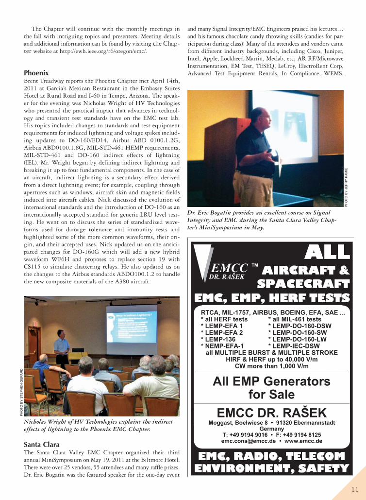
Speaker Lee Hill of Silent demonstrates unintended resonance in shielding at the Chicago MiniSymposium.
The Atwater brothers, Clark and Car-son (left and center), discuss ferrite fil-tering applications with Paul Zdano-wicz of Fair-Rite Products at the Chi-cago MiniSymposium.
10
with his applications talk, “Shielding of Electronic Products, Enclosures and Ca-bles.” He emphasized that the details of implementation and their mechanization usually is more critical to success than strict adherence to theory. After a brief review of shielding effectiveness, Lee illus-trated best practices and theory using sev-eral case studies: 1. Connector cable shield clamps should have 360 degree contact. 2. When to connect a cable shield to the enclosure at one vs. both ends? 3. Risks of using shield pigtail terminations. 4. Choosing the enclosure metal type, thick-ness and conductivity. 5. Understanding the unintended consequences of an en-closure becoming a resonant cavity. Lee included several live physical demonstra-tions which drove the principles home.
The afternoon included another hour break to interact with the exhibitors, ad-ditional raffle drawings and concluded with prizes for the best EMC-Opoly sub-missions. Additional thanks to ELITE for handing the registration and Bob Hof-mann for printing the program booklets.
After another successful MiniSym-posium, the Chapter went on summer hiatus and looked forward to the In-ternational Symposium in August and then resuming the regular program in September. Please check our website for details www.emcchicago.org . Cheerfully submitted by Jerry Meyerhoff, Secretary.
Hong KongThe IEEE Hong Kong EMC Chapter held a successful Technical Forum at the City
University of Hong Kong on 28 May 2011. Mr. Wilson Loke of KEMA Quality Hong Kong Limited presented the first topic titled, “Introduction of Electromagnetic Exposure.” Dr. Brian K. H. Chan of City University of Hong Kong presented the second topic titled, “Real-life Applications of ICNIRP Guidelines to Various Human EMF Exposure Issues,” and Dr. K. C. Lee of Hong Kong Standards and Testing Centre
presented the third topic titled, “Briefing of EN62493 – Assessment of Lighting Equip-ment related to Human Exposure to Elec-tromagnetic Fields”. A total of 53 participants attended the Forum.
Oregon and SW WashingtonAlee Langford, Chapter Vice-Chair, reports that the Oregon and SW Washington Chapter concluded the spring program by welcoming Mark Stefka (Distinguished EMC Lecturer) for the April meeting. The presentation covered EMC approaches applied to automotive systems, from the conventional “legacy” systems to the latest developments in electric vehicle propul-sion. There was discussion about the unique environment that automotive systems function in and how some of the methods used to meet automotive system functional requirements can determine the vehicle’s EMC characteristics. Typical automotive EMC requirements were identified and examined, along with some interesting “case studies”.
Wilson Loke is shown during his presenta-tion to the Hong Kong Chapter on “Intro-duction of Electromagnetic Exposure.”
Pictured are the recent speakers and the committee members of the Hong Kong EMC Chapter. From left, George Chan, Stanton Lui, Dr. Brian Chan, Steven Tsang, Dr. K. C. Lee, Dr. Duncan Fung (Chairman of the Hong Kong EMC Chapter), and Dr. Peter Leung.
Dr. Brian K. H. Chan is shown pre-senting to the Hong Kong Chapter on the topic of “Real-life Applications of ICNIRP Guidelines to Various Human EMF Exposure Issues.”
A recent speaker for the Hong Kong Chapter, Dr. K. C. Lee, is shown pre-senting “Briefing of EN62493 – Assessment of Lighting Equipment related to Human Exposure to Electro-magnetic Fields.”
At a recent meeting of the Oregon and SW Washington Chapter, speaker Mark Steffka (left) is shown with Chapter Chair Mark Briggs. Mark is presenting the speaker with a gift for his outstanding presentation.
11
The Chapter will continue with the monthly meetings in the fall with intriguing topics and presenters. Meeting details and additional information can be found by visiting the Chap-ter website at http://ewh.ieee.org/r6/oregon/emc/.
PhoenixBrent Treadway reports the Phoenix Chapter met April 14th, 2011 at Garcia’s Mexican Restaurant in the Embassy Suites Hotel at Rural Road and I-60 in Tempe, Arizona. The speak-er for the evening was Nicholas Wright of HV Technologies who presented the practical impact that advances in technol-ogy and transient test standards have on the EMC test lab. His topics included changes to standards and test equipment requirements for induced lightning and voltage spikes includ-ing updates to DO-160/ED14, Airbus ABD 0100.1.2G, Airbus ABD0100.1.8G, MIL-STD-461 HEMP requirements, MIL-STD-461 and DO-160 indirect effects of lightning (IEL). Mr. Wright began by defining indirect lightning and breaking it up to four fundamental components. In the case of an aircraft, indirect lightning is a secondary effect derived from a direct lightning event; for example, coupling through apertures such as windows, aircraft skin and magnetic fields induced into aircraft cables. Nick discussed the evolution of international standards and the introduction of DO-160 as an internationally accepted standard for generic LRU level test-ing. He went on to discuss the series of standardized wave-forms used for damage tolerance and immunity tests and highlighted some of the more common waveforms, their ori-gin, and their accepted uses. Nick updated us on the antici-pated changes for DO-160G which will add a new hybrid waveform WF6H and proposes to replace section 19 with CS115 to simulate chattering relays. He also updated us on the changes to the Airbus standards ABDO100.1.2 to handle the new composite materials of the A380 aircraft.
Santa ClaraThe Santa Clara Valley EMC Chapter organized their third annual MiniSymposium on May 19, 2011 at the Biltmore Hotel. There were over 25 vendors, 55 attendees and many raffle prizes. Dr. Eric Bogatin was the featured speaker for the one-day event
and many Signal Integrity/EMC Engineers praised his lectures… and his famous chocolate candy throwing skills (candies for par-ticipation during class)! Many of the attendees and vendors came from different industry backgrounds, including Cisco, Juniper, Intel, Apple, Lockheed Martin, Metlab, etc; AR RF/Microwave Instrumentation, EM Test, TESEQ, LeCroy, ElectroRent Corp, Advanced Test Equipment Rentals, In Compliance, WEMS,
EMC, RADIO, TELECOM ENVIRONMENT, SAFETY
ALL AIRCRAFT &
SPACECRAFT EMC, EMP, HERF TESTS
Dr. Eric Bogatin provides an excellent course on Signal Integrity and EMC during the Santa Clara Valley Chap-ter’s MiniSymposium in May.
PH
OTO
BY
JE
RR
Y R
AM
IE
Nicholas Wright of HV Technologies explains the indirect effects of lightning to the Phoenix EMC Chapter.
PH
OTO
BY
ST
EP
HE
N G
ER
AR
D
12
TechDream, etc., respectively. AR, manu-facturer of broadband and microwave amplifiers, has been a Platinum Sponsor for three consecutive years. LeCroy who
offers oscilloscopes, serial data analyzers, and protocol test solutions joined the event for the first time.
SE MichiganMOM knows best . . . how Method of Moments can solve today’s complex world problems or The Original Green Math was presented April 7, 2011 by Candace and John Suriano to the South-eastern Michigan IEEE EMC Society Chapter. The basis of the talk was Green’s functions developed by self educated George Green in the 19th century. Green’s functions form the basis for the Method of Moments (MOM) which is a numerical method for modeling many problems associated with EMC. MOM is used in the popular Numerical Electro-magnetic Code (NEC) to solve electro-magnetic problems associated with antennas and other radiating structures. The talk reviewed the differences between the moment method and other numerical
techniques such as finite element model-ing and presented examples.
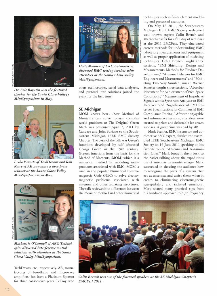
On May 18 2011, the Southeastern Michigan IEEE EMC Society welcomed well known experts Colin Brench and Werner Schaefer for a full day of seminars at the 2011 EMCFest. They elucidated correct methods for understanding EMC laboratory measurements and equipment as well as proper application of modeling techniques. Colin Brench taught three sessions, “EMI Shielding, Design and Measurements Methods for Product De-velopment,” “Antenna Behavior for EMC Engineers and Measurements” and “Mod-eling Two Very Similar Issues.” Werner Schaefer taught three sessions, “Absorber Placement for Achievement of Free-Space Conditions,” “Measurement of Impulsive Signals with a Spectrum Analyzer or EMI Receiver “and “Significance of EMI Re-ceiver Specifications for Commercial EMI Compliance Testing.” After the enjoyable and informative sessions, attendees were treated to prizes and delectable ice cream sundaes. A great time was had by all!
Mark Steffka, EMC instructor and au-tomotive EMC expert, dazzled the assem-bled IEEE Southeastern Michigan EMC Society on 16 June 2011 speaking on his favorite topics, “Antennas and Transmis-sion Lines.” Mark brought them back to the basics talking about the expeditious use of antennas to transfer energy. Mark succeeded in showing the audience how to recognize the parts of a system that act as antennas and assist them when it comes to eliminating electromagnetic susceptibility and radiated emissions. Mark shared many practical tips from his hands-on approach to high frequency
Dr. Eric Bogatin was the featured speaker for the Santa Clara Valley’s MiniSymposium in May.
PH
OTO
BY
JE
RR
Y R
AM
IEP
HO
TO B
Y J
ER
RY
RA
MIE
Eriko Yamato of TechDream and Rob Rowe of AR announce a door prize winner at the Santa Clara Valley MiniSymposium in May.
Mackenzie O’Connell of ARC Technol-ogies discussed interference control solutions with attendees at the Santa Clara Valley MiniSymposium.
PH
OTO
BY
JE
RR
Y R
AM
IE
Colin Brench was one of the featured speakers at the SE Michigan Chapter’s EMCFest 2011.
PH
OTO
BY
JE
RR
Y R
AM
IE
Holly Madden of CKC Laboratories discussed EMC testing services with attendees at the Santa Clara Valley MiniSymposium.
13
electromagnetics. Mark even introduced the latest technology to the room when he showed a ninety-nine cent app for his iPad that gives an antenna’s radiation pattern.
ShanghaiHongmei Fan reports that on May 21, 2011 at the Shanghai University Yanchang Campus, about 10 EMC professionals from various companies gathered for two technical speeches organized by the IEEE EMC Shanghai Chapter.
The first talk was given by an international speaker, Profes-sor Alireza Baghai-Wadji of the RMIT University, Melbourne, Australia. He is an honorary member and fellow of The Elec-tromagnetics Academy, USA. His speech, entitled “Near-field Phenomena in EMC Applications,” introduced an innovative method for simplifying complicated integral expressions for near-field calculations in EM modeling and simulation. The core of his method is referred to as the “natural regularization,” by which certain “unwanted” singular terms cancel out auto-matically in wave-number domain.
The second talk was given by a local ACB Examining En-gineer and iNARTE Certified EMC Engineer, Mr. Qin Zhang. As a technical support manager at the American TCB China Office, he introduced the different requirements of FCC/IC/CE rules or standards for short range devices. During his two hour presentation, the audience gained a broad understanding of pro-found mathematical electromagnetic computations involved in mandatory product EMC certification.
On July 23, 2011 at the Shanghai Jiao Tong University Minhang Campus, 16 EMC professionals and postgraduate stu-dents gathered for a technical speech organized by the IEEE EMC Shanghai Chapter. The talk was given by an interna-tional speaker, Professor Mauro Feliziani of the University of L’Aquila, Italy. Professor Feliziani’s research interests include electromagnetic compatibility, bio-electromagnetics, radio fre-quency identification (RFID), ultra-wideband, wireless com-munications, power line communication, leaky line antennas,
Scott Lytle draws business cards for door prizes at SE Mich-igan’s EMCFest 2011.
Mark Steffka during his June presentation to the SE Mich-igan Chapter on “Antennas and Transmission Lines.”
EMC, RADIO, TELECOM ENVIRONMENT, SAFETY
EMC with
COMPOSITES
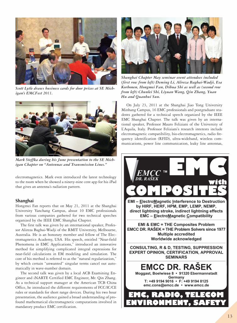
Shanghai Chapter May seminar event attendees included (first row from left) Deming Li, Alireza Baghai-Wadji, Esa Korhonen, Hongmei Fan, Dihua Shi as well as (second row from left) Chunlei Shi, Liyuan Wang, Qin Zhang, Yuan Hu and Quanhui Sun.
14
and micro-electromechanical systems/film bulk acoustic reso-nators. His speech, titled “Advanced Numerical Techniques for EMC-related Bio-electromagnetic and Medical Applications,” introduced advanced numerical models and methods for bio-electromagnetic applications and medical devices. The audience gained a broad understanding of how to model the human body from the viewpoints of physical, electromagnetic and thermal properties. The interesting applications presented included numerical dosimetry of EMF sources, communication perfor-mances of body area network and RFID systems, hyperthermia and wireless power transfer in implanted medical devices.
The IEEE EMC Shanghai Chapter would like to thank Pro-fessor Liang Zhou of the Shanghai Jiao Tong University and Professor Wenyan Yin of the Zhejiang University for facilitat-ing this seminar.
SingaporeRichard Gao Xianke, Chair of IEEE EMC Singapore Chapter, reports that Mr. Donald Heirman, Life Fellow of IEEE and the Chairman of the IEC Special International Committee on Radio Interference (CISPR), was invited by the Singapore EMC Chap-ter to deliver a speech entitled, “Selected EMC Standards and the Process from Start to Finish” at the Institute of High Perfor-
mance Computing (IHPC) of A*STAR, Singapore, on 16 June 2011. There were a total of 14 attendees (seven were IEEE mem-bers) from universities, research institutes and industrial compa-nies. Dr. William Radasky accompanied Don for the presentation and also provided some excellent remarks during the talk.
On 24 June 2011, Chapter Chair, Dr. Richard Gao Xianke, updated the Chapter activities and reviewed the Chapter plan with committee members at the second Chapter administrative meeting. The treasurer, Dr. Liu Enxiao, also updated the finance report. In the afternoon, Professor Tie Jun Cui from Southeast University, China, delivered a technical talk entitled, “Metamate-rials and Their Applications in Microwaves” at the National Uni-versity of Singapore (NUS). There was an overwhelming response with a total of 45 attendees, of which 20 were IEEE members.
Shanghai Chapter July seminar event attendees included (first row from left) Dihua Shi, Liang Zhou, Esa Korhonen, Mauro Feliziani, Hongmei Fan, Tianhong Xu, Qingqing Zhang as well as (second row from left) Lizheng Zhang, Shunchuan Yang, Yuan Hu, Menglin Zhai, Mingda Zhu, Gaowei Shi, Xing Zhao and Qiliang Pan.
Shown during a campus tour at Shanghai Jiao Tong Univer-sity after Shanghai’s July seminar event are (from left) Hong-mei Fan, Esa Korhonen, Mauro Feliziani, and Yuan Hu.
Participants listened attentively during Mr. Donald Heir-man’s seminar at the A*STAR Institute of High Perfor-mance Computing in Singapore on 16 June 2011.
Mr. Donald Heirman joined Dr. William A. Radasky and Dr. Richard Gao Xianke (from right to left) at the Fusion-opolis in Singapore, on 16 June 2011.
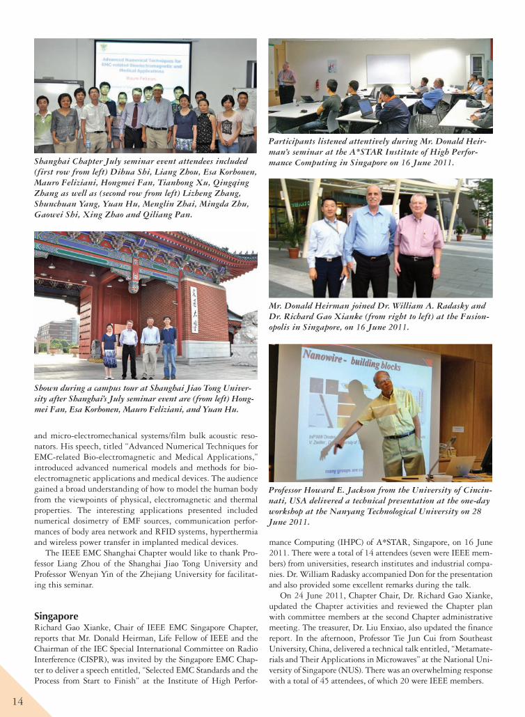
Professor Howard E. Jackson from the University of Cincin-nati, USA delivered a technical presentation at the one-day workshop at the Nanyang Technological University on 28 June 2011.
15
On 27 June 2011, Professor Cui gave another presentation entitled, “Computational Electromagnetics and Applications” at the Temasek Laboratories at the NUS. A total of 21 attendees (11 were IEEE members) participated the seminar.
On 28 June 2011, the EMC Chapter, MTT/AP Chapter and Nanyang Technological University (NTU) jointly organized a one-day workshop of “Advanced Microwave and Photonic Materials and Devices” at NTU. Six renowned professors de-livered excellent presentations to the audience from universi-ties, research institutes and industrial companies. There were of total of 158 attendees of which 78 were IEEE members.
The first speaker was Professor Howard E. Jackson from the University of Cincinnati, USA. His talk was entitled, “Photo-modulated Reflectance Spectroscopy of Single Semiconductor Nanowires.” The second speaker was Professor Paul Harrison from the University of Leeds, UK. He presented, “Terahertz Quantum Cascade Lasers.” Professor Hongxing Jiang from Texas Tech University, USA, was the third speaker and his talk was entitled, “III-nitride Photonics on Si Substrates.” The next speaker was Professor Vijay K. Arora from Wilkes
Professor Paul Harrison from the University of Leeds, UK, delivered a technical presentation at the one-day workshop at the Nanyang Technological University on 28 June 2011.
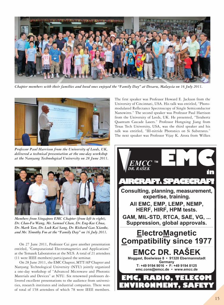
Chapter members with their families and loved ones enjoyed the “Family Day” at Desaru, Malaysia on 16 July 2011.
Members from Singapore EMC Chapter (from left to right), Dr. Chao-Fu Wang, Mr. Samuel Chan, Dr. Eng-Kee Chua, Dr. Mark Tan, Dr. Lock Kai Sang, Dr. Richard Gao Xianke, and Mr. Timothy Foo at the “Family Day” on 16 July 2011.
EMC
EMC, RADIO, TELECOM ENVIRONMENT, SAFETY
in
AIRCRAFT &SPACECRAFT
16
University, USA, who delivered the talk entitled, “Ballistic Transport in Nanow-ires and Carbon Nanotubes.” The fifth speaker was Professor Tie Jun Cui from the Southeast University of China, who presented the talk entitled, “Controlling Microwaves Using Metamaterials and the Applications.” The last speaker was Professor Sailing He from the Royal In-stitute of Technology-Zhejiang Univer-sity Joint Center of Photonics, Sweden, who delivered the talk entitled, “Some Recent Studies of Zero-Index Metama-terials and Nano-/Micro- Hybrid Plas-monic Structures.”
On 16 July 2011, “Family Day 2011” was jointly organized by the EMC and MTT/AP Chapters. The purpose is to mingle our members and friends from industry and academia and spend valu-able time with families and beloved ones. This was a one day tour trip to Desaru, Malaysia. All participants, es-pecially the children, were very excited to visit the ostrich farm, fruit farm, and mini zoo. The most exciting thing was riding on the boats for firefly viewing in a late evening. I cite one comment from a Chapter member, Dr. Lock, after the trip, “… a wonderful day trip which members of my family and I very much enjoyed. The itinerary was well-planned and details well taken care of. This is my first participation in the MTT/AP and EMC joint Chapter Family event. I would like to express my appreciation to fellow members for the friendliness, cooperation and consideration which made the trip a success. It was a pleasure meeting several old friends and many new friends.”
United Kingdom and Republic of IrelandOn July 13, 2011, the UK and RI Chap-ter held a meeting at the Visitor Centre of the Tyseley Railway Works in Bir-mingham, UK. The program included a mix of technical presentations on EMC topics which were connected wherever possible with railways.
The first presentation had the un-likely title, “EMC of Steam Locomotives” in which Rob Morland gave an account of the planning and construction of the Tornado steam locomotive which was the first main line steam locomotive to be constructed in the UK since 1960. The electrical and electronic content required to allow use on main lines presented quite a few problems as coal dust and electron-ics do not mix. The videos of the Tornado under steam were a treat for some of the old timers present.
A paper on “Magnetic Fields from DC Light Rail Transit Systems” by Ade Ogunsola was presented by Ivo Skalicky and provided useful insight into the
methods of minimizing emissions caused by the large currents involved.
Chris Marshman of York EMC Ser-vices gave a presentation on “Recent Railway EMC Projects” in which he showed a wealth of – sometimes alarm-ing – track side emission measure-ments. He also provided some insight
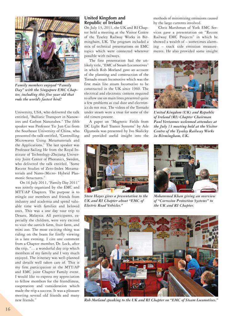
Family members enjoyed “Family Day” with the Singapore EMC Chap-ter, including this five year old that rode the world’s fastest bird!
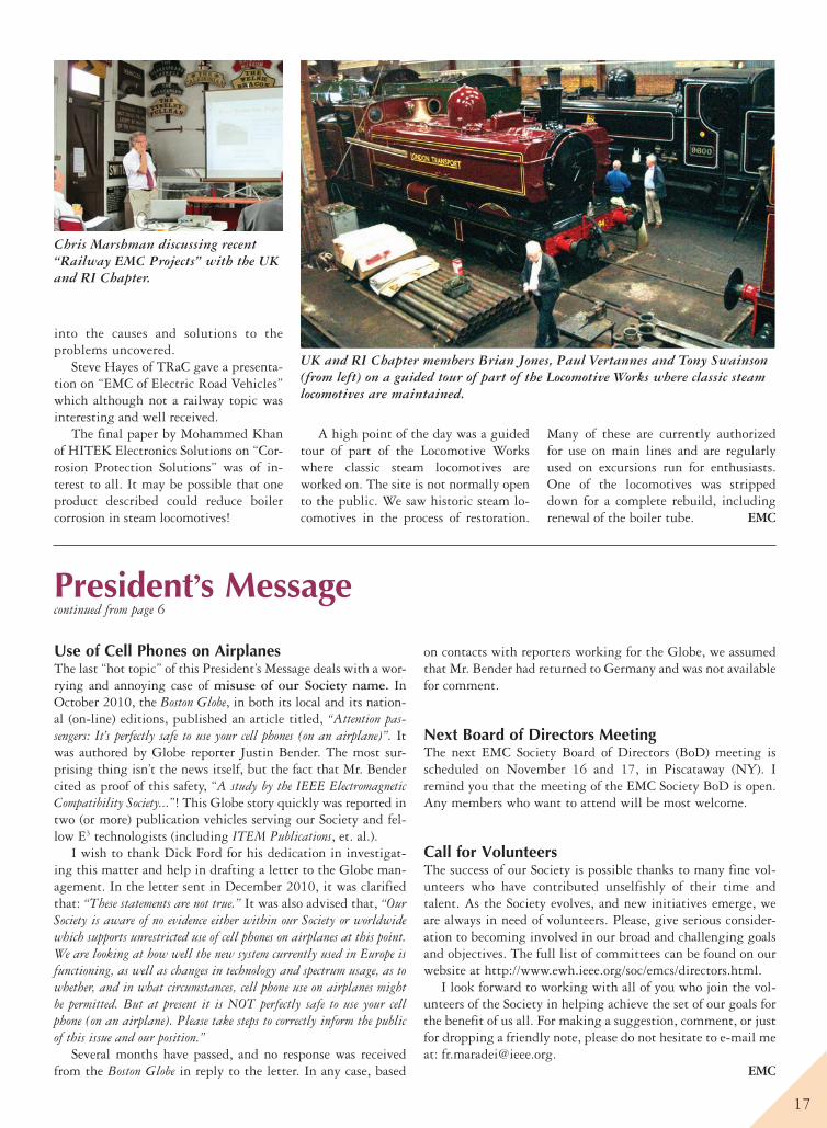
United Kingdom (UK) and Republic of Ireland (RI) Chapter Chairman Paul Vertannes welcomed attendees at the July 13 meeting held at the Visitor Centre of the Tyseley Railway Works in Birmingham, UK.
Rob Morland speaking to the UK and RI Chapter on “EMC of Steam Locomotives.”
Steve Hayes gives a presentation to the UK and RI Chapter about “EMC of Electric Road Vehicles.”
Mohammed Khan giving an overview of “Corrosion Protection Systems” to the UK and RI Chapter.
17
President’s Messagecontinued from page 6
Use of Cell Phones on AirplanesThe last “hot topic” of this President’s Message deals with a wor-rying and annoying case of misuse of our Society name. In October 2010, the Boston Globe, in both its local and its nation-al (on-line) editions, published an article titled, “Attention pas-sengers: It’s perfectly safe to use your cell phones (on an airplane)”. It was authored by Globe reporter Justin Bender. The most sur-prising thing isn’t the news itself, but the fact that Mr. Bender cited as proof of this safety, “A study by the IEEE Electromagnetic Compatibility Society...”! This Globe story quickly was reported in two (or more) publication vehicles serving our Society and fel-low E3 technologists (including ITEM Publications, et. al.).
I wish to thank Dick Ford for his dedication in investigat-ing this matter and help in drafting a letter to the Globe man-agement. In the letter sent in December 2010, it was clarified that: “These statements are not true.” It was also advised that, “Our Society is aware of no evidence either within our Society or worldwide which supports unrestricted use of cell phones on airplanes at this point. We are looking at how well the new system currently used in Europe is functioning, as well as changes in technology and spectrum usage, as to whether, and in what circumstances, cell phone use on airplanes might be permitted. But at present it is NOT perfectly safe to use your cell phone (on an airplane). Please take steps to correctly inform the public of this issue and our position.”
Several months have passed, and no response was received from the Boston Globe in reply to the letter. In any case, based
on contacts with reporters working for the Globe, we assumed that Mr. Bender had returned to Germany and was not available for comment.
Next Board of Directors MeetingThe next EMC Society Board of Directors (BoD) meeting is scheduled on November 16 and 17, in Piscataway (NY). I remind you that the meeting of the EMC Society BoD is open. Any members who want to attend will be most welcome.
Call for VolunteersThe success of our Society is possible thanks to many fine vol-unteers who have contributed unselfishly of their time and talent. As the Society evolves, and new initiatives emerge, we are always in need of volunteers. Please, give serious consider-ation to becoming involved in our broad and challenging goals and objectives. The full list of committees can be found on our website at http://www.ewh.ieee.org/soc/emcs/directors.html.
I look forward to working with all of you who join the vol-unteers of the Society in helping achieve the set of our goals for the benefit of us all. For making a suggestion, comment, or just for dropping a friendly note, please do not hesitate to e-mail me at: [email protected].
EMC
into the causes and solutions to the problems uncovered.
Steve Hayes of TRaC gave a presenta-tion on “EMC of Electric Road Vehicles” which although not a railway topic was interesting and well received.
The final paper by Mohammed Khan of HITEK Electronics Solutions on “Cor-rosion Protection Solutions” was of in-terest to all. It may be possible that one product described could reduce boiler corrosion in steam locomotives!
A high point of the day was a guided tour of part of the Locomotive Works where classic steam locomotives are worked on. The site is not normally open to the public. We saw historic steam lo-comotives in the process of restoration.
Many of these are currently authorized for use on main lines and are regularly used on excursions run for enthusiasts. One of the locomotives was stripped down for a complete rebuild, including renewal of the boiler tube. EMC
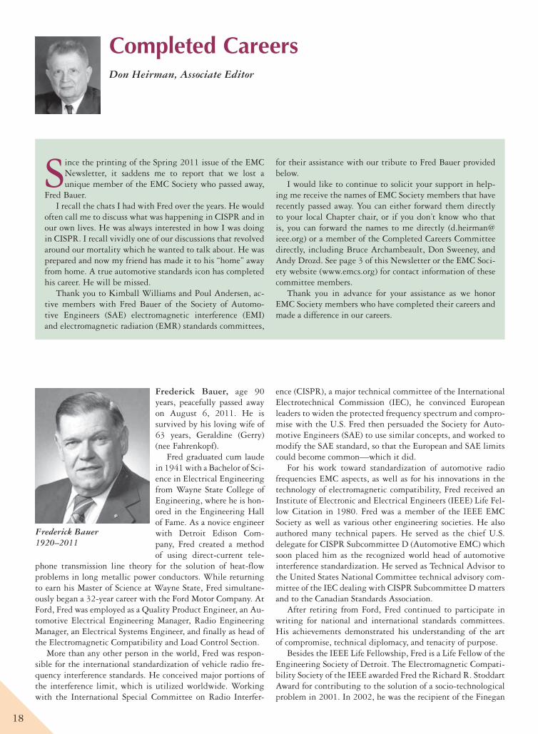
Chris Marshman discussing recent “Railway EMC Projects” with the UK and RI Chapter.
UK and RI Chapter members Brian Jones, Paul Vertannes and Tony Swainson (from left) on a guided tour of part of the Locomotive Works where classic steam locomotives are maintained.
18
Completed CareersDon Heirman, Associate Editor
Since the printing of the Spring 2011 issue of the EMC Newsletter, it saddens me to report that we lost a unique member of the EMC Society who passed away,
Fred Bauer. I recall the chats I had with Fred over the years. He would
often call me to discuss what was happening in CISPR and in our own lives. He was always interested in how I was doing in CISPR. I recall vividly one of our discussions that revolved around our mortality which he wanted to talk about. He was prepared and now my friend has made it to his “home” away from home. A true automotive standards icon has completed his career. He will be missed.
Thank you to Kimball Williams and Poul Andersen, ac-tive members with Fred Bauer of the Society of Automo-tive Engineers (SAE) electromagnetic interference (EMI) and electromagnetic radiation (EMR) standards committees,
for their assistance with our tribute to Fred Bauer provided below.
I would like to continue to solicit your support in help-ing me receive the names of EMC Society members that have recently passed away. You can either forward them directly to your local Chapter chair, or if you don’t know who that is, you can forward the names to me directly ([email protected]) or a member of the Completed Careers Committee directly, including Bruce Archambeault, Don Sweeney, and Andy Drozd. See page 3 of this Newsletter or the EMC Soci-ety website (www.emcs.org) for contact information of these committee members.
Thank you in advance for your assistance as we honor EMC Society members who have completed their careers and made a difference in our careers.
Frederick Bauer, age 90 years, peacefully passed away on August 6, 2011. He is survived by his loving wife of 63 years, Geraldine (Gerry) (nee Fahrenkopf).
Fred graduated cum laude in 1941 with a Bachelor of Sci-ence in Electrical Engineering from Wayne State College of Engineering, where he is hon-ored in the Engineering Hall of Fame. As a novice engineer with Detroit Edison Com-pany, Fred created a method of using direct-current tele-
phone transmission line theory for the solution of heat-flow problems in long metallic power conductors. While returning to earn his Master of Science at Wayne State, Fred simultane-ously began a 32-year career with the Ford Motor Company. At Ford, Fred was employed as a Quality Product Engineer, an Au-tomotive Electrical Engineering Manager, Radio Engineering Manager, an Electrical Systems Engineer, and finally as head of the Electromagnetic Compatibility and Load Control Section.
More than any other person in the world, Fred was respon-sible for the international standardization of vehicle radio fre-quency interference standards. He conceived major portions of the interference limit, which is utilized worldwide. Working with the International Special Committee on Radio Interfer-
ence (CISPR), a major technical committee of the International Electrotechnical Commission (IEC), he convinced European leaders to widen the protected frequency spectrum and compro-mise with the U.S. Fred then persuaded the Society for Auto-motive Engineers (SAE) to use similar concepts, and worked to modify the SAE standard, so that the European and SAE limits could become common—which it did.
For his work toward standardization of automotive radio frequencies EMC aspects, as well as for his innovations in the technology of electromagnetic compatibility, Fred received an Institute of Electronic and Electrical Engineers (IEEE) Life Fel-low Citation in 1980. Fred was a member of the IEEE EMC Society as well as various other engineering societies. He also authored many technical papers. He served as the chief U.S. delegate for CISPR Subcommittee D (Automotive EMC) which soon placed him as the recognized world head of automotive interference standardization. He served as Technical Advisor to the United States National Committee technical advisory com-mittee of the IEC dealing with CISPR Subcommittee D matters and to the Canadian Standards Association.
After retiring from Ford, Fred continued to participate in writing for national and international standards committees. His achievements demonstrated his understanding of the art of compromise, technical diplomacy, and tenacity of purpose.
Besides the IEEE Life Fellowship, Fred is a Life Fellow of the Engineering Society of Detroit. The Electromagnetic Compati-bility Society of the IEEE awarded Fred the Richard R. Stoddart Award for contributing to the solution of a socio-technological problem in 2001. In 2002, he was the recipient of the Finegan
Frederick Bauer 1920–2011
19
8th International Workshop on ElectromagneticCompatibility of Integrated Circuits
EMC Compo 2011November 6 - 9, 2011, Dubrovnik, Croatia
www.emccompo2011.org
CALL FOR PAPERS“EMC-Aware Design from IC to System Level”
The achievements in terms of operating frequency and integration of semiconductor technology are constantly creating new challenges in EMC, power and signal integrity, which must necessarily be addressed at both the integrated circuit and system level. Keeping up-to-date is of paramount importance to be successful in this field. Following earlier EMC Compo events, the International Workshop EMC Compo 2011 is a place to be for exchange of the latest research achievements and experience in IC-level EMC up to application on a PCB. This workshop is addressed to researchers from industry and academia as for tool providers and equipment suppliers in these fields.
The workshop event is focused on emission and susceptibility as well as power and signal integrity issues of digital, analogue and mixed-signal integrated circuits. The most recent advances in simulation and measurement techniques, modelling, standards, tools, design, design flows and verification methodologies will be discussed. A Technical Exhibition will provide tool providers, equipment manufacturers and suppliers an opportunity to display their products, services and to discuss them with potential clients.
HighlightsTutorials by distinguished experts in the field of EMC of ICs is organized on: Wednesday, November 9th
A panel discussion on Tuesday, November 8th followed by a social event/dinner in the eveningKey-note presentations in opening sessions on Monday, November 7th, and Tuesday, November 8th
A PhD seminar will be organized on Sunday afternoon, November 6th.PhD students conducting research in EMC of ICs are invited to present their work at this event.Best paper and best student paper awards
Main Topics
Paper SubmissionComplete papers should be written in English and submitted in PDF format (max. 6 pages including title, 100-word abstract, illustrations and references). The contributions should be submitted electronically through the website: www.emccompo2011.org, where further information on paper preparation is available.
Deadline for paper submission: May 16th, 2011Notification of acceptance: July 10th, 2011Final Paper due date: September 19th, 2011
Workshop VenueDubrovnik, a city renowned for its beauty, is situated in the southern part of Croatia. The Old City of Dubrovnik, founded in the 7th century, with its rich cultural and historical monuments is included in the UNESCO World Heritage List. One of the lovely features of Dubrovnik is that one can make a tour of its churches, monasteries, museums, palaces and city walls on foot. EMC Compo 2011 is hosted by the Centre for Advanced Academic Studies, which is very close to the Old City and guarantees warm atmosphere for participants.
Contacts and InformationMore location and organization details can be found on the workshop website: www.emcompo2011.orgFor further information do not hesitate to contact the organizing committee at [email protected]
• Measurement and modelling of IC susceptibility • EMC-aware IC design and guidelines • Measurement and modelling of IC emission • EMC-driven IC/PCB co-design • EMC issues in System-on-Chip • Tools to handle EMC at IC-level• EMC issues in System-in-Package (SiP) • Computational Electromagnetics for IC-level EMC• EMC issues in smart power ICs • Harsh environment effects on IC-level EMC • EMC of ICs in wireless communications • Long-term electromagnetic robustness of ICs • EMC of ICs for biomedical applications • Extending EMC standards and regulations up to 6 GHz• Materials for improved EMC of ICs • Modern EMC education on IC-level EMC • Signal Integrity and Power Integrity on PCB-level
Organizing CommitteeGeneral chair:Renaud Gillon, On SemiconductorTechnical program chairs:Georges Gielen, K.U. LeuvenAdrijan Baric, Univ. of ZagrebPublication/publicity chair:Davy Pissoort, KHBO – K.U. LeuvenFinancial chair:Zeljko Butkovic, Univ. of ZagrebPosters/demo chair:Vladimir Ceperic, Univ. of ZagrebPhD session chair:Franco Fiori, Politecnico di TorinoTutorials chair:Sonia Ben Dhia, INSA-ToulouseIEEE Liaison chair:Johan Catrysse, KHBO K.U. LeuvenIndustry Liaison chair:Mart Coenen, EMCMCC
Past conference chairs:Etienne Sicard, INSA-ToulouseThomas Steinecke, InfineonFranco Fiori, Politecnico di TorinoMohamed Ramdani, ESEO
Technical Program CommitteeAdrijan Baric, Univ. of ZagrebSonia Ben Dhia, INSA-ToulouseAlexandre Boyer, INSA ToulouseMart Coenen, EMCMCCBernd Deutschmann, InfineonFranco Fiori, Politecnico di TorinoGeorges Gielen, K.U. LeuvenRenaud Gillon, On SemiconductorTodd Hubing, Clemson UniversityElya B. Joffe, KTM Proj. Eng.Werner John, Leibniz Univ. HannoverUwe Keller, ZukenFrank Klotz, InfineonFrederic Lafon, VALEOJean-Luc Levant, Atmel NantesErping Li, A*STAR, SingaporeChristian Marot, EADS-IWWolfgang Mathis, Leibniz U. HannoverOlivier Maurice, GeracMauro Merlo, ST-MicroelectronicsJan Niehof, NXPDavid Pommerenke, Missouri S&TUDavide Pandini, ST-MicroelectronicsRichard Perdriau, ESEODavy Pissoort, KHBO – K.U. LeuvenHugo Pues, MelexisMohamed Ramdani, ESEOMiquel Roca, Univ. Iles BalearesBob Ross, Teraspeed Consulting GroupGoeran Schubert, TemicEtienne Sicard, INSA ToulouseKevin Slattery, IntelThomas Steinecke, InfineonIgor Stievano, Politecnico di TorinoBoris Traa, PhilipsBertrand Vrignon, Freescale ToulouseOsami Wada, Kyoto UniversityWolfgang Wilkening, BoschShih-Yi Yuan, Feng-Chia University
20
Standards Medal of the American National Standards Institute, which honors an individual who has shown extraordinary lead-ership in the actual development and application of voluntary standards.
Fred was an avid railroad aficionado. He was the co-author of a full-length book, “The Moffat Road,” a history of Colorado mountain railroading, which won an award from the American Association of State and Local History. Fred’s collection of forty railroad drumheads (these were drum head sized advertisements placed at the rear of the passenger observation car identifying the RR name) is on display in the Frederick Bauer Drumhead Gal-lery at the National Railroad Museum in Green Bay, Wisconsin.
Fred was a fourth generation Detroiter and a great-grandson of Bernhard Stroh, founder of the Stroh Brewery Company. He was a past president of the Dearborn Historical Commission and the Sacred Heart Parish Council. As a member of the Apos-tleship of the Sea for 11 years, Fred welcomed seafarers arriving in Detroit ports and offered them food, the opportunity to call home, attend Mass, or shop.
Fred and Gerry extensively traveled the world togeth-er but also enjoyed weekends at their cottage in Caseville, Michigan. Fred was ecstatic if a freighter or train were in view. Besides his wedding day on June 26, 1948, one of Fred’s happiest days was spent as a guest engineer on the Denver & Rio Grande Western railroad, the highest standard gauge rail running south from Denver, Colorado through the Rockies. Fred’s smile, humor, and sharp wit will be remembered by all who knew him.
For our EMC Society, Kim Williams (past president of the EMC Society) recalls that Fred was active as a speaker for their local SW Michigan EMC chapter several times before his health began to fail. His last talk for the chapter was on March 12, 2002. As his health failed, Kim would often drive Fred to Chapter events, and to the SAE EMC Standards meetings. He kept his full wits right to the end, and would often challenge other ‘experts’ on topics where he felt there was insufficient data to warrant a suspect decision--but, he always did this as a gentleman. EMC
IEEE TECHNOLOGY
MANAGEMENT COUNCILThe IEEE Technology Management Council provides tools to enhance your career and organizational effectiveness. We can keep you current with managerial, business, and entrepreneurial thinking whether you are an executive, an aspiring manager, a technical professional, or student.
Visit www.ieee.org/tmc to join your colleagues today!
Francesca MaradeiIEEE EMC Society President (2010-2011)
© 2011 Agilent Technologies, Inc.
Agilent N9038A MXE EMI Receiver
CISPR 16-1-1 2010 compliant
Built-in X-Series analyzer runs applications
Intuitive interface and graphical displays
Upgradable for long-term fl exibility
When you fi nd a device out of EMI compliance, now you can also understand why. Because the new Agilent receiver is also an X-Series signal analyzer, loaded with diagnostics to show what’s happening.That’s thinking ahead. That’s Agilent.
u.s. 1-800-829-4444 canada 1-877-894-4414
Verifying EMC performance is one thing.Diagnosing the cause of EMI is quite another.
22
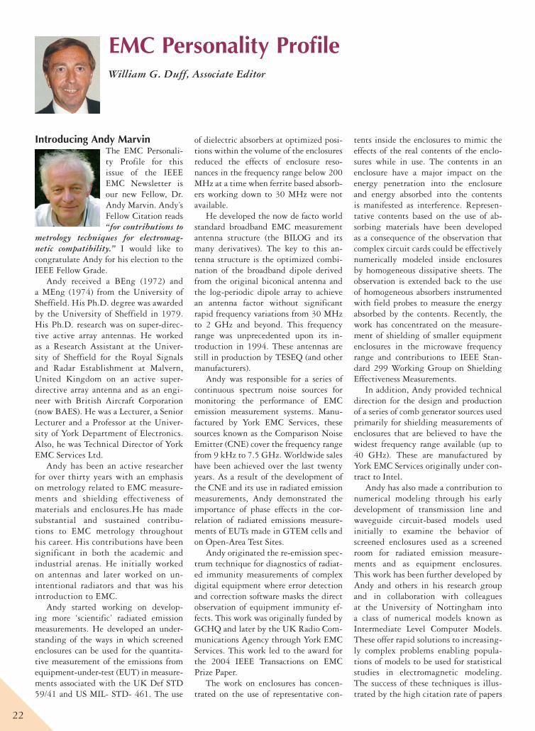
EMC Personality ProfileWilliam G. Duff, Associate Editor
Introducing Andy MarvinThe EMC Personali-ty Profile for this issue of the IEEE EMC Newsletter is our new Fellow, Dr. Andy Marvin. Andy’s Fellow Citation reads “for contributions to
metrology techniques for electromag-netic compatibility.” I would like to congratulate Andy for his election to the IEEE Fellow Grade.
Andy received a BEng (1972) and a MEng (1974) from the University of Sheffield. His Ph.D. degree was awarded by the University of Sheffield in 1979. His Ph.D. research was on super-direc-tive active array antennas. He worked as a Research Assistant at the Univer-sity of Sheffield for the Royal Signals and Radar Establishment at Malvern, United Kingdom on an active super-directive array antenna and as an engi-neer with British Aircraft Corporation (now BAES). He was a Lecturer, a Senior Lecturer and a Professor at the Univer-sity of York Department of Electronics. Also, he was Technical Director of York EMC Services Ltd.
Andy has been an active researcher for over thirty years with an emphasis on metrology related to EMC measure-ments and shielding effectiveness of materials and enclosures.He has made substantial and sustained contribu-tions to EMC metrology throughout his career. His contributions have been significant in both the academic and industrial arenas. He initially worked on antennas and later worked on un-intentional radiators and that was his introduction to EMC.
Andy started working on develop-ing more ‘scientific’ radiated emission measurements. He developed an under-standing of the ways in which screened enclosures can be used for the quantita-tive measurement of the emissions from equipment-under-test (EUT) in measure-ments associated with the UK Def STD 59/41 and US MIL- STD- 461. The use
of dielectric absorbers at optimized posi-tions within the volume of the enclosures reduced the effects of enclosure reso-nances in the frequency range below 200 MHz at a time when ferrite based absorb-ers working down to 30 MHz were not available.
He developed the now de facto world standard broadband EMC measurement antenna structure (the BILOG and its many derivatives). The key to this an-tenna structure is the optimized combi-nation of the broadband dipole derived from the original biconical antenna and the log-periodic dipole array to achieve an antenna factor without significant rapid frequency variations from 30 MHz to 2 GHz and beyond. This frequency range was unprecedented upon its in-troduction in 1994. These antennas are still in production by TESEQ (and other manufacturers).
Andy was responsible for a series of continuous spectrum noise sources for monitoring the performance of EMC emission measurement systems. Manu-factured by York EMC Services, these sources known as the Comparison Noise Emitter (CNE) cover the frequency range from 9 kHz to 7.5 GHz. Worldwide sales have been achieved over the last twenty years. As a result of the development of the CNE and its use in radiated emission measurements, Andy demonstrated the importance of phase effects in the cor-relation of radiated emissions measure-ments of EUTs made in GTEM cells and on Open-Area Test Sites.
Andy originated the re-emission spec-trum technique for diagnostics of radiat-ed immunity measurements of complex digital equipment where error detection and correction software masks the direct observation of equipment immunity ef-fects. This work was originally funded by GCHQ and later by the UK Radio Com-munications Agency through York EMC Services. This work led to the award for the 2004 IEEE Transactions on EMC Prize Paper.
The work on enclosures has concen-trated on the use of representative con-
tents inside the enclosures to mimic the effects of the real contents of the enclo-sures while in use. The contents in an enclosure have a major impact on the energy penetration into the enclosure and energy absorbed into the contents is manifested as interference. Represen-tative contents based on the use of ab-sorbing materials have been developed as a consequence of the observation that complex circuit cards could be effectively numerically modeled inside enclosures by homogeneous dissipative sheets. The observation is extended back to the use of homogeneous absorbers instrumented with field probes to measure the energy absorbed by the contents. Recently, the work has concentrated on the measure-ment of shielding of smaller equipment enclosures in the microwave frequency range and contributions to IEEE Stan-dard 299 Working Group on Shielding Effectiveness Measurements.
In addition, Andy provided technical direction for the design and production of a series of comb generator sources used primarily for shielding measurements of enclosures that are believed to have the widest frequency range available (up to 40 GHz). These are manufactured by York EMC Services originally under con-tract to Intel.
Andy has also made a contribution to numerical modeling through his early development of transmission line and waveguide circuit-based models used initially to examine the behavior of screened enclosures used as a screened room for radiated emission measure-ments and as equipment enclosures. This work has been further developed by Andy and others in his research group and in collaboration with colleagues at the University of Nottingham into a class of numerical models known as Intermediate Level Computer Models. These offer rapid solutions to increasing-ly complex problems enabling popula-tions of models to be used for statistical studies in electromagnetic modeling. The success of these techniques is illus-trated by the high citation rate of papers
23
describing the technique. One example is the seventh most cited paper in the IEEE EMC Transactions in the last twen-ty five years. It now has 144 citations (source – Google Scholar). This work is being developed further by Andy’s group as part of a major EU aerospace research program, HIRF-SE.
In addition to his research work, Andy has been active in EMC educa-tion including running a Masters Degree program at York for a number of years. He has taught many industrial courses on EMC since 1982 and this year at the 2011 IEEE International Symposium on EMC he is due to contribute again to the Global EMC University and to the EMC Fundamentals Tutorial.
Andy has been involved in various professional activities. He has been a member of he IEEE for 26 years, served on the EMC Society Board of Directors, was Associate Editor of the Transactions on EMC, Chair and Faulty Member of the IEEE EMC Society Global EMC Uni-versity, and Vice-Chair of IEEE Standard
299 Working Group on Shielding Effec-tiveness Measurements.
Andy was Co-Founder (along with Professor Antonio Orlandi) of the EMC Aviators’ Club. Founded in 2007, this club is open to all IEEE EMC Society members who have an interest in avia-tion. They meet at symposia and on other professional visits and encourage members to arrange to fly together where possible. See the club website at http://orlandi.ing.univaq.it/EMCfly/index.htm for more information.
Andy has also been active in the IEE Professional Group on EMC. He was a Member of the IEE Professional Group on the Fundamental Aspects of Measure-ment. He was awarded the “Maxwell Pre-mium” and the “Marconi Premium” (two awards) for co-authorship with a gradu-ate student of three papers in the IEE Proceedings on Science Measurement and Technology. He was UK Delegate to URSI Commission A (Electromagnetic Metrology) and a Member of the R & D Advisory Committee for the UK Nation-
al Measurement System. He is currently Chair of the EMC Europe 2011 York Conference.
Andy has been married to Heather for 35 years. She is a volunteer manager at the local hospice and is a keen musician. Her string quartet will be playing at the EMC Europe 2011 York Dinner. They enjoy mountain walking together.
For fun, Andy flies gliders (proper gliders with big white wings – not hang gliders) and trains glider flying instruc-tors.
Also, Andy samples the local beer where ever he goes to establish that noth-ing beats a decent pint of English bitter served at a sensible temperature (10C or 50F).
Andy and Heather have a daughter Ros who is a hospital doctor in Cam-bridge but may soon also be a profession-al photographer. Their son Tom is based in the French Alps as part of a three man start-up company selling sustainable ad-venture holidays.
EMC
Cuming Lehman Chambers, Inc.T 717.263.4101 Chambersburg, PA 17201 | CumingLehman.com
Dedicated to Designing and BuildingState-of-the-Art Anechoic Chamber Facilities
DESIGN, ENGINEERING & CONSTRUCTION SERVICES | HOST STRUCTURES | ANECHOIC TEST CHAMBERS | MATERIALS DEVELOPMENT | RF & SPECIALTY ABSORBERS
Cuming Microwave CorporationT 508.580.2660 | 800.432.6464 Avon, MA 02322 | CumingMW.com
Over 50 years of construction experience Over 20 years of anechoic chamber design and manufacturing expertise Industry leader for custom-built, RF shielded facilitiesDedication to quality, on-time delivery, and customer satisfaction
Call Us Today at 717.263.4101Call Us Today at 717.263.4101
24
EMC Society HistoryDaniel D. Hoolihan, Associate Editor, Chair of the EMC Society History Committee
Introduction to the EMC Society History SectionIn this Newsletter we have three articles for the History Section.
Our look back into the history of the EMC Society starts with the EMC Society Newsletters from August of 1961, the Summer of 1986, and the Summer of 2001. All three Newslet-ters have valuable information in them! I hope you enjoy read-ing my synopses of the Newsletters.
The second article is a reprint of the “Quasies and Peaks” newsletter from May of 1955. As you may remember, the “Quasies and Peaks” newsletter was a private newsletter that was edited by Rexford Daniels who became the first official edi-tor of the Professional Group on Radio Frequency Interference (RFI’s) newsletter in 1957 with the simultaneous origin of the PGRFI as part of the Institute of Radio Engineers (IRE). We
are reprinting these for your reading enjoyment and for archival purposes.
The third article addresses the issue of “digitizing hard-copy records.” As we mature as an engineering Society, we need to concern ourselves with storing and archiving our im-portant Society records. We should also be concerned with archiving our member’s valuable hard-copy contributions to our profession.
To be the most value to future engineers in the EMC disci-pline, the records must be readily available and they must be ‘keyword’ searchable to ease the finding of important ideas and topics. How should we do this as an engineering Society is an issue the Board of Directors needs to address.
Happy Reading and keep those cards and e-mails coming!EMC
Fifty Years Ago – August 1961 – Newsletter Number 17 – Institute of Radio Engineers (IRE) Professional Group on Radio Frequency Interfer-ence (PGRFI)The cover page of the Newsletter carried a “Letter of Appre-ciation from our Chairman.” The letter was addressed to Mr. D. R. J. White, Don White Associates, 7306 Honeywell Lane, Bethesda, Maryland. The letter said: Dear Don: On behalf of the officers and members of PGRFI, I should like to express my thanks and sincere appreciation for the effort which you personally devoted to the conduct of the 3rd National Sympo-sium on Radio Frequency Interference. Without question, this Symposium was the best of the three that were held from the point of view of not only attendance but quality and general interest. I would also like you to extend to the other members of your committee our appreciation for their contributions. The Symposium was certainly conducted with an unusual degree of smoothness for this type of affair. With best personal regards – Sincerely yours, R. M. Showers, Chairman, PGRFI, 1960–1961.
The Third National Symposium for the PGRFI was held on June 12-13, 1961 at the Sheraton-Park Hotel in Wash-ington, D. C. A picture from the Newsletter showing, on the left, Major-General James Dreyfus, J-6 Communica-tions, Department of Defense, the Key-Note Speaker for the Third National Symposium, and, on the right, Donald D. R. J. White, Chairman of the Third National Symposium is reproduced at right.
The middle of the Newsletter contained a “Preliminary Announcement of the Seventh Armour Conference.” It said “The following is the preliminary announcement of the Seventh Conference on Radio Interference Reduction and Elec-tronic Compatibility to be held November 7, 8, and 9, 1961:
Sponsored jointly by the three military services, the Seventh Conference will be conducted by Armour Research Foundation on the campus of the Illinois Institute of Technology in Chicago. TECHNICAL TOPICS – Sessions are being organized to cover such areas as electromagnetic compatibility analysis, design and measurement techniques, interference prediction techniques, data processing and display method, practical interference con-trol and reduction, etc. It is also planned that topics relating
EMC Society Newsletter Articles 50–25–10 Years Ago
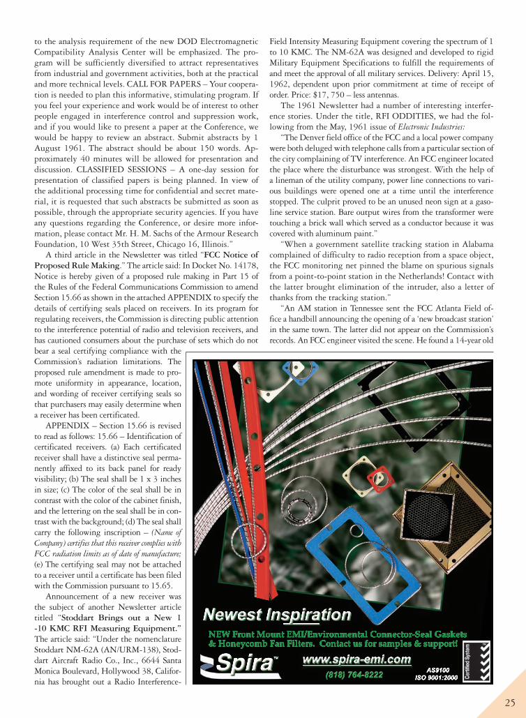
25
to the analysis requirement of the new DOD Electromagnetic Compatibility Analysis Center will be emphasized. The pro-gram will be sufficiently diversified to attract representatives from industrial and government activities, both at the practical and more technical levels. CALL FOR PAPERS – Your coopera-tion is needed to plan this informative, stimulating program. If you feel your experience and work would be of interest to other people engaged in interference control and suppression work, and if you would like to present a paper at the Conference, we would be happy to review an abstract. Submit abstracts by 1 August 1961. The abstract should be about 150 words. Ap-proximately 40 minutes will be allowed for presentation and discussion. CLASSIFIED SESSIONS – A one-day session for presentation of classified papers is being planned. In view of the additional processing time for confidential and secret mate-rial, it is requested that such abstracts be submitted as soon as possible, through the appropriate security agencies. If you have any questions regarding the Conference, or desire more infor-mation, please contact Mr. H. M. Sachs of the Armour Research Foundation, 10 West 35th Street, Chicago 16, Illinois.”
A third article in the Newsletter was titled “FCC Notice of Proposed Rule Making.” The article said: In Docket No. 14178, Notice is hereby given of a proposed rule making in Part 15 of the Rules of the Federal Communications Commission to amend Section 15.66 as shown in the attached APPENDIX to specify the details of certifying seals placed on receivers. In its program for regulating receivers, the Commission is directing public attention to the interference potential of radio and television receivers, and has cautioned consumers about the purchase of sets which do not bear a seal certifying compliance with the Commission’s radiation limitations. The proposed rule amendment is made to pro-mote uniformity in appearance, location, and wording of receiver certifying seals so that purchasers may easily determine when a receiver has been certificated.
APPENDIX – Section 15.66 is revised to read as follows: 15.66 – Identification of certificated receivers. (a) Each certificated receiver shall have a distinctive seal perma-nently affixed to its back panel for ready visibility; (b) The seal shall be 1 x 3 inches in size; (c) The color of the seal shall be in contrast with the color of the cabinet finish, and the lettering on the seal shall be in con-trast with the background; (d) The seal shall carry the following inscription – (Name of Company) certifies that this receiver complies with FCC radiation limits as of date of manufacture; (e) The certifying seal may not be attached to a receiver until a certificate has been filed with the Commission pursuant to 15.65.
Announcement of a new receiver was the subject of another Newsletter article titled “Stoddart Brings out a New 1 -10 KMC RFI Measuring Equipment.” The article said: “Under the nomenclature Stoddart NM-62A (AN/URM-138), Stod-dart Aircraft Radio Co., Inc., 6644 Santa Monica Boulevard, Hollywood 38, Califor-nia has brought out a Radio Interference-
Field Intensity Measuring Equipment covering the spectrum of 1 to 10 KMC. The NM-62A was designed and developed to rigid Military Equipment Specifications to fulfill the requirements of and meet the approval of all military services. Delivery: April 15, 1962, dependent upon prior commitment at time of receipt of order. Price: $17, 750 – less antennas.
The 1961 Newsletter had a number of interesting interfer-ence stories. Under the title, RFI ODDITIES, we had the fol-lowing from the May, 1961 issue of Electronic Industries:
“The Denver field office of the FCC and a local power company were both deluged with telephone calls from a particular section of the city complaining of TV interference. An FCC engineer located the place where the disturbance was strongest. With the help of a lineman of the utility company, power line connections to vari-ous buildings were opened one at a time until the interference stopped. The culprit proved to be an unused neon sign at a gaso-line service station. Bare output wires from the transformer were touching a brick wall which served as a conductor because it was covered with aluminum paint.”
“When a government satellite tracking station in Alabama complained of difficulty to radio reception from a space object, the FCC monitoring net pinned the blame on spurious signals from a point-to-point station in the Netherlands! Contact with the latter brought elimination of the intruder, also a letter of thanks from the tracking station.”
“An AM station in Tennessee sent the FCC Atlanta Field of-fice a handbill announcing the opening of a ‘new broadcast station’ in the same town. The latter did not appear on the Commission’s records. An FCC engineer visited the scene. He found a 14-year old
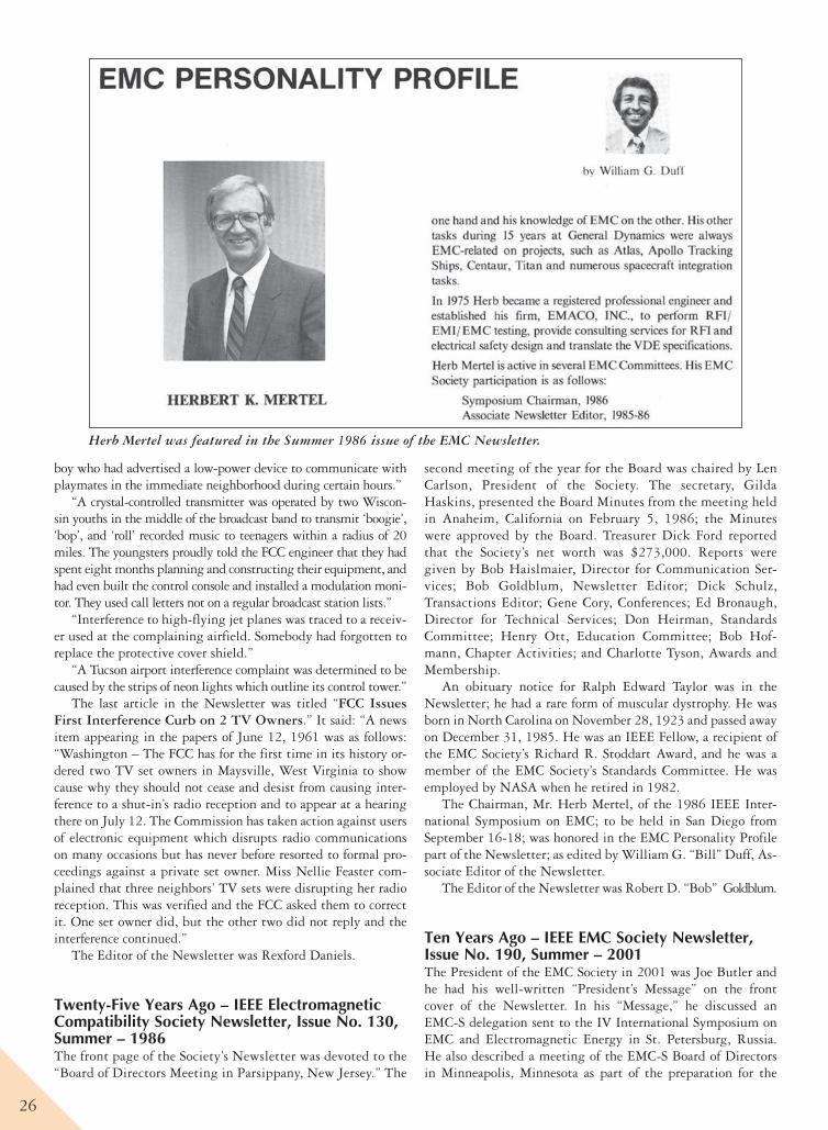
26
boy who had advertised a low-power device to communicate with playmates in the immediate neighborhood during certain hours.”
“A crystal-controlled transmitter was operated by two Wiscon-sin youths in the middle of the broadcast band to transmit ‘boogie’, ‘bop’, and ‘roll’ recorded music to teenagers within a radius of 20 miles. The youngsters proudly told the FCC engineer that they had spent eight months planning and constructing their equipment, and had even built the control console and installed a modulation moni-tor. They used call letters not on a regular broadcast station lists.”
“Interference to high-flying jet planes was traced to a receiv-er used at the complaining airfield. Somebody had forgotten to replace the protective cover shield.”
“A Tucson airport interference complaint was determined to be caused by the strips of neon lights which outline its control tower.”
The last article in the Newsletter was titled “FCC Issues First Interference Curb on 2 TV Owners.” It said: “A news item appearing in the papers of June 12, 1961 was as follows: “Washington – The FCC has for the first time in its history or-dered two TV set owners in Maysville, West Virginia to show cause why they should not cease and desist from causing inter-ference to a shut-in’s radio reception and to appear at a hearing there on July 12. The Commission has taken action against users of electronic equipment which disrupts radio communications on many occasions but has never before resorted to formal pro-ceedings against a private set owner. Miss Nellie Feaster com-plained that three neighbors’ TV sets were disrupting her radio reception. This was verified and the FCC asked them to correct it. One set owner did, but the other two did not reply and the interference continued.”
The Editor of the Newsletter was Rexford Daniels.
Twenty-Five Years Ago – IEEE Electromagnetic Compatibility Society Newsletter, Issue No. 130, Summer – 1986The front page of the Society’s Newsletter was devoted to the “Board of Directors Meeting in Parsippany, New Jersey.” The
second meeting of the year for the Board was chaired by Len Carlson, President of the Society. The secretary, Gilda Haskins, presented the Board Minutes from the meeting held in Anaheim, California on February 5, 1986; the Minutes were approved by the Board. Treasurer Dick Ford reported that the Society’s net worth was $273,000. Reports were given by Bob Haislmaier, Director for Communication Ser-vices; Bob Goldblum, Newsletter Editor; Dick Schulz, Transactions Editor; Gene Cory, Conferences; Ed Bronaugh, Director for Technical Services; Don Heirman, Standards Committee; Henry Ott, Education Committee; Bob Hof-mann, Chapter Activities; and Charlotte Tyson, Awards and Membership.
An obituary notice for Ralph Edward Taylor was in the Newsletter; he had a rare form of muscular dystrophy. He was born in North Carolina on November 28, 1923 and passed away on December 31, 1985. He was an IEEE Fellow, a recipient of the EMC Society’s Richard R. Stoddart Award, and he was a member of the EMC Society’s Standards Committee. He was employed by NASA when he retired in 1982.
The Chairman, Mr. Herb Mertel, of the 1986 IEEE Inter-national Symposium on EMC; to be held in San Diego from September 16-18; was honored in the EMC Personality Profile part of the Newsletter; as edited by William G. “Bill” Duff, As-sociate Editor of the Newsletter.
The Editor of the Newsletter was Robert D. “Bob” Goldblum.
Ten Years Ago – IEEE EMC Society Newsletter, Issue No. 190, Summer – 2001The President of the EMC Society in 2001 was Joe Butler and he had his well-written “President’s Message” on the front cover of the Newsletter. In his “Message,” he discussed an EMC-S delegation sent to the IV International Symposium on EMC and Electromagnetic Energy in St. Petersburg, Russia. He also described a meeting of the EMC-S Board of Directors in Minneapolis, Minnesota as part of the preparation for the
Herb Mertel was featured in the Summer 1986 issue of the EMC Newsletter.
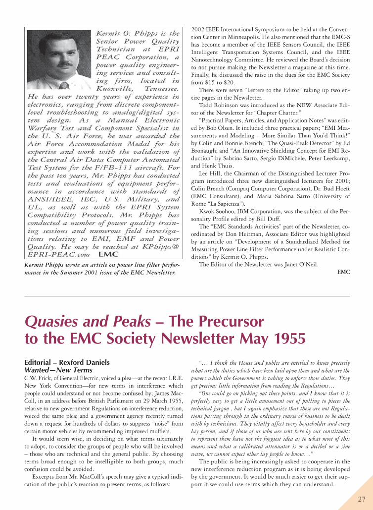
27
2002 IEEE International Symposium to be held at the Conven-tion Center in Minneapolis. He also mentioned that the EMC-S has become a member of the IEEE Sensors Council, the IEEE Intelligent Transportation Systems Council, and the IEEE Nanotechnology Committee. He reviewed the Board’s decision to not pursue making the Newsletter a magazine at this time. Finally, he discussed the raise in the dues for the EMC Society from $15 to $20.
There were seven “Letters to the Editor” taking up two en-tire pages in the Newsletter.
Todd Robinson was introduced as the NEW Associate Edi-tor of the Newsletter for “Chapter Chatter.”
“Practical Papers, Articles, and Application Notes” was edit-ed by Bob Olsen. It included three practical papers; “EMI Mea-surements and Modeling – More Similar Than You’d Think!” by Colin and Bonnie Brench; “The Quasi-Peak Detector” by Ed Bronaugh; and “An Innovative Shielding Concept for EMI Re-duction” by Sabrina Sarto, Sergio DiMichele, Peter Leerkamp, and Henk Thuis.
Lee Hill, the Chairman of the Distinguished Lecturer Pro-gram introduced three new distinguished lecturers for 2001; Colin Brench (Compaq Computer Corporation), Dr. Bud Hoeft (EMC Consultant), and Maria Sabrina Sarto (University of Rome “La Sapienza”).
Kwok Soohoo, IBM Corporation, was the subject of the Per-sonality Profile edited by Bill Duff.
The “EMC Standards Activities” part of the Newsletter, co-ordinated by Don Heirman, Associate Editor was highlighted by an article on “Development of a Standardized Method for Measuring Power Line Filter Performance under Realistic Con-ditions” by Kermit O. Phipps.
The Editor of the Newsletter was Janet O’Neil. EMC
Quasies and Peaks – The Precursor to the EMC Society Newsletter May 1955Editorial – Rexford Daniels Wanted—New TermsC.W. Frick, of General Electric, voiced a plea—at the recent I.R.E. New York Convention—for new terms in interference which people could understand or not become confused by; James Mac-Coll, in an address before British Parliament on 29 March 1955, relative to new government Regulations on interference reduction, voiced the same plea; and a government agency recently turned down a request for hundreds of dollars to suppress “noise” from certain motor vehicles by recommending improved mufflers.
It would seem wise, in deciding on what terms ultimately to adopt, to consider the groups of people who will be involved – those who are technical and the general public. By choosing terms broad enough to be intelligible to both groups, much confusion could be avoided.
Excerpts from Mr. MacColl’s speech may give a typical indi-cation of the public’s reaction to present terms, as follows:
“… I think the House and public are entitled to know precisely what are the duties which have been laid upon them and what are the powers which the Government is taking to enforce those duties. They get precious little information from reading the Regulations…
“One could go on picking out these points, and I know that it is perfectly easy to get a little amusement out of pulling to pieces the technical jargon , but I again emphasize that these are not Regula-tions passing through in the ordinary course of business to be dealt with by technicians. They vitally affect every householder and every lay person, and if those of us who are sent here by our constituents to represent them have not the foggiest idea as to what most of this means and what a calibrated attenuator is or a decibel or a sine wave, we cannot expect other lay people to know…”
The public is being increasingly asked to cooperate in the new interference reduction program as it is being developed by the government. It would be much easier to get their sup-port if we could use terms which they can understand.
Kermit Phipps wrote an article on power line filter perfor-mance in the Summer 2001 issue of the EMC Newsletter.
28
Articles of Interest
Bureau of Ships Journal, April 1955:Charleston Develops Field Change for Radar Interference Reduction,by W.E. Rohe, Jr., Charleston Naval Shipyard, and M.L. McClary, International Electronics Engineering Company.
New Way to Calibrate TS-587/U Is Suggested.New-Type Interference-Free Fluorescent Lamp is Developed, by
Leonard Thomas, Electronics Design and Development Divi-sion, Bureau of Ships.
Electronics, May 1955:Band-Pass Filters Using Strip-Line Techniques, by E.H. Bradley and D.R.J. White, Melpar, Inc., Alexandria, Va. (Design and construc-tion data on filters for insertion in coaxial lines to obtain band-pass filter performance with large savings in space and weight. Use of etched wiring and sandwich constructions simplifies fabrication.)
UP dispatch, April 6, 1955:Report Radio from Jupiter – Scientists Describe Pickup of Planet’s Static Bursts.
The report was made to the American Astronomical Society at Princeton, N.J. by Drs. Bernard F. Burke and Kenneth L. Frank-lin of the Carnegie Institute at Washington. “What causes these radio waves of a frequency of 22 megacycles remains to be ex-plained,” Dr. Burke said. “The emissions are probably produced by violent disturbances in the atmosphere of Jupiter, similar to our thunderstorms, but on a much larger scale.”
In Lighter VeinWireless World, April 1955 – as submitted by Dr. R.M. Show-ers, University of Pennsylvania. (Excerpts)The Curse of Kissing
“The only thing that interested me in the doctor’s talk (over B.B.C.) was his statement that he knew a married couple who caused an electric spark to jump from one to the other each time they kissed. Apparently this is not an isolated phenomenon, for when this statement was published in the Press several letters subsequently appeared which showed it to be quite common….
“From a technical point of view I don’t think it is possible to sup-press this interference unless kissing is only permitted in specially screened apartments.”
Recent PapersCase Experiences with Interference Reduction for F.C.C. Certification, by T.P. Kinn, Consultant,
Baltimore, Md. American Institute of Electrical Engineers, Committee of Electric Heating, Electric Heating Conference, Chicago, Ill. May 10–11, 1955.
Joint meeting International Scientific Radio Union and Institute of Radio Engineers, Washington, D.C., May 2–5, 1955.A Method of Measurement of a Two-terminal Impedance, by B. Salz-berg and K.W. Bewig, Naval Research Laboratory.
A Probability Computer for Noise Measurement, by J.D. Wells and A.W. Sullivan, University of Florida.
The Effect of Atmospheric Noise on Manual Radiotelegraph Sys-tem, by R. F. Brown, University of Florida.
The Effect of Atmospheric Noise on Frequency-Shift Radioteletype System, by Samuel P. Hersperger, University of Florida.
Studies in Noise by the Liouville Theorem, by G. Held, Univer-sity of Washington.
On the Radar Measurement of Angle-of-Arrival in the Presence of Many Plane Wave Interference, by H.R. Brewer and R.D. Wether-ington, Georgia Institute of Technology.
A Study of Fading Rate in Long Distance Tropospheric Wave Propagation, by A.P. Barsis, National Bureau of Standards.
A Combination Crystal Switch Circuit, by F.S. Coale, Sperry Gyroscope Company.
Characteristics of High Frequency Discharges from Severe Storms, by Herbert L. Jones, Oklahoma Agricultural and Mechanical College.
Atmospheric Noise Characteristics, by A.W. Sullivan, Univer-sity of Florida.
The Measurement of Recurrent Impulsive Noise, by A. Eckersley and D. B. Geselowitz, University of Pennsylvania.
Data on the Temperature Dependence of X-Ban Fluorescent Lamp Noise Sources, by W.W. Mumford and R.L. Schafersman, Bell Telephone Laboratories.
Noise Measurements in the UHF Range, by E. Maxwell and B.J. Leon, Massachusetts Institute of Technology.
The Influence of Noise in Radio Reception, by S. Matt and O.J. Jacomini, General Electric Company.
Who’s Who in Interference ReductionBurroughs Corporation, Radio Interference Laboratories, Detroit 32, Mich.
James J. Krause, Chief Electrical Test Engineer Harrison I. Craig, Electronics Engineer Sylvester F. Pelowski, Electronics EngineerThe Glenn L. Martin Company, Baltimore 2, Md.
C.F.W. Anderson, Design SpecialistBell Aircraft Corp., P.O. Box 1, Buffalo, New York.
E.H. EckertW.L. PlicatoR.L. SchneiderJ.J.Skehan
Chance Vought Aircraft, Inc., P.O. Box 5907, Dallas, Texas.J.L. Gette
Northrop Aircraft, Inc., Hawthorne, California.D.M. Hill
Piasecki Helicopter Corp., 100 Woodland Ave., Morton, Pa.J.R. MooreIn line with compiling a glossary of terms in the inter-
ference reduction field, we would be very glad to print any new terms which have been coined by anyone in this field. Please send them in together – with a description of what they cover.
From letters which have come in, there seems to be a grow-ing demand for the formation of some sort of technical group for the exchange of information. The I.R.E. is now in process of forming a group within its own organization but, for some time to come, it will of necessity have to concentrate on technical aspects. In the meantime, there is a great deal of general infor-mation which should be circulated. EMC

30
Digitizing Historical EMC Society RecordsDaniel D. Hoolihan Chair, History Committee IEEE
IntroductionRecently, there has been a flurry of interest within the Electromag-netic Compatibility Society of the IEEE relative to “digitizing”historical documents and records of the Society. The interest is keyed to the “aging” of our members coupled with the constant technological change we are experiencing. This article takes a look at that issue and recommends some possible avenues of cooperation for our members.
Hard-Copy RecordsHistorically, the EMC Society has stored its records in hard-copy format. Since our Society is only 54 years old, this has been a satisfactory solution. When we want to research a topic, we look to find the information in hard-copy format.
For example, in researching the 50th Anniversary of the Society in 2007, we (the 50th Anniversary Committee) relied heavily on paper copies of the EMC-S Transactions, the IEEE International Symposium on EMC publications, the EMC-S Newsletter, and personal records of Founders of the Society.
As the Chair of the Society’s History Committee, I rely heavily on my personal hard-copy library of the above-men-tioned documents. For example, to write the article in this issue on “50-25-10 Years Ago”; I relied on donated News-letters from Ed Bronaugh and Leonard Thomas, both EMC Society Members. Mr. Bronaugh donated his Newsletters voluntarily for the 50th Anniversary while Mr. Thomas’s do-nations were gleaned from his numerous file cabinets in the basement of his home in the Washington, DC area some years after his death.
We can always read hard-copy records if they are stored safe-ly and they are not damaged by the ravages of time and environ-ment. It is difficult to store paper records because they take a lot of space and we do not have an EMC Society library in which to store the records.
Micro-Fiche RecordsIn the early 1990s, Chester ‘Chet’ Smith was the Society’s His-tory Committee Chair and he spearheaded a project to put our records on Micro-Fiche. He succeeded in capturing the News-
letters from 1957 through 1991 plus the Quasies and Peaks Newsletter in the mid-1950s. He also had all the Armour Con-ference Records from the 1950s and early 1960s plus the IEEE Symposium Records through 1992.
Unfortunately, micro-fiche readers are a rarity these days and, beside the Society’s present History Committee Chair (the author); who else has a copy of the microfiche records?
Electronic RecordsThe IEEE and the EMC Society of the IEEE have been working on “digitizing” the Society’s records. These records are then accessed through the IEEE Xplore program.
This is a convenient solution to storing the records and doc-uments of the EMC Society.
At the present time, we can access at least the following So-ciety records:1. IEEE Transactions on RFI–19632. IEEE Transactions on EMC–1964–20113. IEEE International Symposium on EMC–1988–20104. IEEE EMC Society Newsletter–Winter/2003–Present (Issues
196–229).Unfortunately, we have numerous records and documents
that are not yet digitized and available on Xplore. This includes the RFI Transactions from 1957 -1962 and the IEEE Interna-tional Symposium on EMC conference records from 1957 – 1988. Also, the Newsletters from 1957 – 2003 and the Armour Conference Records in the 1950s.
In addition to the Society’s missing records, we have many private papers from engineering individuals in the So-ciety that could be very valuable for future research in the area of EMC engineering. How do we decide what to save in a digital format? Who makes the decision? The Society’s Board of Directors?
How could individual EMC Chapters help on this project? Could they scan documents into a system that is compatible with Xplore? Could volunteers scan documents into Xplore or must it be done by a professional organization?
Your thoughts and ideas are solicited. Send them to the Chair of the History Committee, [email protected].
EMC
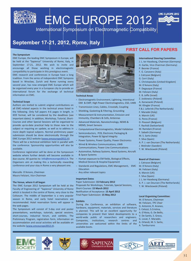
31
September 17-21, 2012, Rome, ItalyFIRST CALL FOR PAPERS
EMC EUROPE 2012 International Symposium on Electromagnetic Compatibility
The SymposiumEMC Europe, the leading EMC Symposium in Europe, willbe held at the “Sapienza” University of Rome, Italy, inSeptember 17 21, 2012. We wish to invite andencourage all those working in electromagneticcompatibility to participate in this prestigious event.EMC research and conferences in Europe have a longtradition. From the series of independent EMC Symposiabased in Wroclaw, Zurich and Rome running everysecond year, has now emerged EMC Europe which willbe organised every year in a European city to provide aninternational forum for the exchange of technicalinformation on EMC.
Technical ScopeAuthors are invited to submit original contributions onall EMC related aspects in the technical areas listed inthe following. Only full papers 4 6 pages in length, inIEEE format, will be considered by the deadlines (seeimportant dates). In addition, Workshop, Tutorial, ShortCourses and other Special Sessions will be organised toprovide up to date practical help to those new to thesubject or requiring an update, as well as to address inmore depth topical subjects. Normal preliminary papersubmission should be done electronically through theEMC Europe 2012 website (www.emceurope2012.it).There will be a technical exhibition held in parallel withthe conference. Sponsorship opportunities will also beavailable.Conference registration will be done at the Symposiumwebsite where further details will become available indue course. All queries to: [email protected]. TheOrganisers aim at making this a technically rewardingconference and your stay in Rome a very pleasant one.
Marcello D’Amore, ChairmanMauro Feliziani, Vice Chairman
The Venue, where it all beganThe EMC Europe 2012 Symposium will be held at theFaculty of Engineering of "Sapienza" University of Romewhich is located in the centre of Rome, very close to theColiseum. The middle of September is a very popularseason in Rome, and early hotel reservations arerecommended. Hotel reservation forms will appear inthe web pages.The Symposium will consist of 5 day oral and posterpresentations, workshops, tutorials, special sessions,short courses, industrial forum, and exhibits. ThePreliminary Program, registration form, information onaccommodation and social activities will be available onthe website (www.emceurope2012.it).
Technical Areas
- Electromagnetic Environment, Lightning, IntentionalEMI & EMP, High Power Electromagnetics, ESD, UWB
- Transmission Lines, Cables, Crosstalk, Coupling
- Shielding, Gasketing & Filtering, Grounding
- Measurement & Instrumentation, Emission andImmunity, Chambers & Cells, Antennas
- Advanced Materials, Nanotechnology, NEMS &MEMS, Smart Sensors
- Computational Electromagnetics, Model Validation
- Semiconductors, PCB, Electronic Packaging &Integration, Power & Signal Integrity
- Power Systems, Power Quality, Power Electronics
- Wired & Wireless Communications, UWBCommunications, Power Line Communications
- Automotive, Railway Systems, Naval Systems, Aircraft& Space Systems
- Human exposure to EM fields, Biological Effects,Medical Devices & Hospital Equipment
- Standards and Regulations, EMC Management, EMCEducation
- Any other relevant topics
Important DatesPaper Submission: 15 February 2012Proposals for Workshops, Tutorials, Special Sessions,Short Courses: 15 March 2012Notification of Acceptance: 15 April 2012Final Paper Submission: 15 May 2012
ExhibitsDuring the Conference, an exhibition of software,hardware, equipment, materials, services and literatureis planned. This will be an excellent opportunity forcompanies to present their latest developments to aworld wide public of researchers and engineers.Companies, institutions, research centres anduniversities are welcomed within the limits of theavailable boots.
International Steering CommitteeJ. L. ter Haseborg, Chairman (Germany)H. Garbe, Vice Chairman (Germany)P. Besnier (France)F. G. Canavero (Italy)J. Catrysse (Belgium)G. Cerri (Italy)C. Christopoulos (United Kingdom)M. D’Amore (Italy)P. Degauque (France)M. Feliziani (Italy)E. B. Joffe (Israel)Z. Joskiewicz (Poland)A. Karwowski (Poland)M. Klingler (France)F.B.J. Leferink (The Netherlands)F. Maradei (Italy)A. Marvin (UK)G. Peres (France)D. Pissoort (Belgium)F. Rachidi (Switzerland)M. Ramdani (France)F. Sabath (Germany)M. S. Sarto (Italy)F. Silva (Spain)A. P. J. van Deursen (The Netherlands)J. Welinder (Sweden)T. W. Wieckowski (Poland)
Board of Chairmen:J. Catrysse (Belgium)M. D’Amore (Italy)M. Feliziani (Italy)A. Marvin (UK)F. Silva (Spain)J. L. ter Haseborg (Germany)A. P. J. van Deursen (The Netherlands)T. W. Wieckowski (Poland)
Local Organising Committee:M. D’Amore, ChairmanM. Feliziani, TPC ChairG. Antonini, R. Araneo,S. Celozzi, S.Cristina,A. D’Aloia, G. De Bellis,V. De Santis, S. Greco,G. Lovat, F. Maradei,A. Orlandi, M. S. Sarto,A. Tamburrano
being held on
August 5-10, 2012
in the city of bridges,
Pittsburgh, Pennsylvania.
This event will have
something for everyone —
from the novice EMC
engineer to the advanced
practitioner. This is an
opportunity to advance
your knowledge, build new
relationships, and reconnect
with industry friends from
around the world.
www.emc2012.isemc.org
Cross over to the2012 IEEEInternational Symposium onElectromagnetic Compatibility
BRIDGE TO EMC
INFORMATION for AuthorsThe IEEE EMC Society seeks original, unpublished papers covering all aspects of EMC and in technologies that are affected by EMC (including but not limited to shielding, ESD, automotive, broadcast, military, wireless, smart grid, and power transmission.)
Join your colleagues in Pittsburgh where you can share your insight, ask questions, learn from the experts/innovators and see new products at the 2012 IEEE International Symposium on Electromagnetic Compatibility. Your published paper will be seen by thousands in the global EMC community via IEEE Xplore as well as by those attending the symposium. This is a unique opportunity for your paper to receive unlimited exposure and be read by those, across a wide array of disciplines, that look to the IEEE EMC Society for technical guidance.
PAPER TOPICS of InterestTopics include and are not limited to the following technical areas.TC-1 EMC Management
TC-2 EMC Measurements
TC-3 EM Environment
Author Submission Schedule
November 1, 2011 - January 15, 2012(late papers will not be accepted)
See web site for more details www.emc2012.ISEMC.org
TC-4 EM Interference
TC-5 High Power Electromagnetics
TC-6 Spectrum Management
TC-9 Computational Electromagnetics
TC-10 Signal Integrity
TC-11 Nanotechnology & Advanced Materials
SC1: Smart Grid EMC
SC2: Low Frequency EMC
SC3: Transportation System EMC
EMC 2012Symposium CommitteeGeneral Chairman - Mike OliverVice Chairman - Ed NakauchiSecretary - Bob DavisTreasurer/Finance - John LaSalleTechnical Program Chair - Bruce ArchambeaultTechnical Paper Chair - Jun FanExperiments & Demonstrations Co-Chairs Sam ConnorBob ScullySpecial Sessions Chair - Colin BrenchWorkshops & Tutorials Chair - John MaasYouth Technical Program - Amy PinchukJob Fair Chair - Kimball WilliamsSpecial Liaison - Advisor - Janet O’NeilRegistration - Tammy Cox - ChairIrina KasperovichJoyce FenicalExhibits Chair - Andy DrozdPublications Chair - John RohrbaughJanet Nichols - EditorMarketing Chair - Alee LangfordLocal Arrangements -Dennis Lewis - ChairRhonda Rodriguez - Co-ChairCompanions Program - Judy RohrbaughConference Manager - John Vanella
34 ©2011 IEEE
Practical Papers, Articles and Application NotesKye Yak See, Technical Editor
I hope you enjoyed reading the three papers published in the Spring 2011 issue in this section of the EMC News-letter. For this current issue, I am delighted to present to
you an additional three quality contributions covering a wide range of EMC-related subjects: electrostatic discharge (ESD), the concept of electrical dimension, and a causality issue in electromagnetic simulation.
The first paper, “Easy Access to Pulsed Hertzian Dipole Fields Through Pole-Zero Treatment,” was contributed by Timothy J. Maloney from Intel Corporation. Tim’s rich expe-riences in ESD protection design for semiconductor devices have led to breakthroughs in ESD performance enhance-ments for a wide variety of Intel products. In this paper, based on a Laplace Transform approach, he cleverly derives the s-domain radiated field equations for a pulsed current source. The result is a pole-zero expression similar to that of the ordinary circuit analysis, where time-dependent fields at any distance can be calculated through easily accessible inverse Laplace Transform software. The time-domain radi-ated fields are useful for one to assess how the charged device model’s ESD radiations can be detected.
The second paper entitled “Physical Dimensions versus Electrical Dimensions” is authored by our regular contribu-tor, Professor Clayton Paul. With digital circuits operating at higher speeds and shorter logic transition times, digital circuit designers are confused about the condition in which to apply a lumped circuit or transmission line model for their circuit analyses. They will find the answer in this pa-
per. Dr. Paul shares with us how to determine the condition where the interconnect lines connecting the source and the load become electrically long. Hence, the standard lumped-circuit model is no longer valid and the transmission line model is necessary.
The last paper entitled, “A Simple Causality Checker and Its Use in Verifying, Enhancing, and Depopulating Tabulated Data from Electromagnetic Simulation,” is joint-ly authored by Brian Young and Amarjit S Bhandal from Texas Instruments USA and UK, respectively. With more powerful and accurate EM simulators available in the mar-ket, they become valuable tools for analyzing complex EMC problems. How do you know that the simulated results are correct, reliable, and usable? Causality check is one effective way to ensure that the simulated results are accurate and valid. Brian and Amarjit share with us the implementation details of a simple causality checker. The causality checker is used to derive an algorithm for selecting sampling rates and bandwidth for EM extractions of good interconnects, enabling a potentially large reduction in data points and run time. The improved extraction data has been shown to sig-nificantly improve S-parameter data and time domain simu-lation accuracy.
In conclusion, your active participation as authors and reviewers is needed so as to make this column a quality read. I wish you an enjoyable and fulfilling summer and feel free to share with me your feedback and comments, preferably by email at [email protected].
Easy Access to Pulsed Hertzian Dipole Fields Through Pole-Zero TreatmentTimothy J. Maloney, Intel Corporation, Santa Clara, CA; [email protected]
Abstract: The equations for EM dipole near and far radiation fields are formulated for the complex frequency domain with a Laplace Transform analysis for Hertzian dipoles. An s-domain pulsed current source function from ordinary circuit analysis is used in the expressions, and is augmented as needed to refine the pulse. This formulation allows a lucid pole-zero treatment of the field transfer function, yielding any field at any distance through the inverse Laplace Transform. Zeros of these expres-sions always include the “radiation zeros”, essential properties of the dipole fields themselves. Methods for recovery of current pulse waveforms from E- and H-field measurements, using filter functions, are described. The inverse Laplace Transform of
pole-zero expressions through Heaviside expansion is more accessible than ever through free web applets and commonly available software. Study of the small pulsed dipole has become important in semiconductor manufacturing, as engineers seek to monitor and control charged device model ESD events that could destroy components.
IntroductionDipole radiation is treated in many physics and engineering textbooks on electromagnetism (EM), only a few of which are cited here [1–3]. The most familiar treatment results in
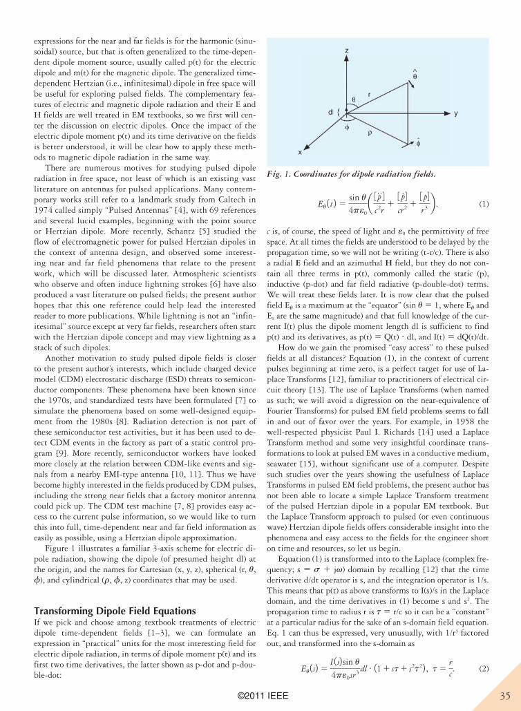
35©2011 IEEE
expressions for the near and far fields is for the harmonic (sinu-soidal) source, but that is often generalized to the time-depen-dent dipole moment source, usually called p(t) for the electric dipole and m(t) for the magnetic dipole. The generalized time-dependent Hertzian (i.e., infinitesimal) dipole in free space will be useful for exploring pulsed fields. The complementary fea-tures of electric and magnetic dipole radiation and their E and H fields are well treated in EM textbooks, so we first will cen-ter the discussion on electric dipoles. Once the impact of the electric dipole moment p(t) and its time derivative on the fields is better understood, it will be clear how to apply these meth-ods to magnetic dipole radiation in the same way.
There are numerous motives for studying pulsed dipole radiation in free space, not least of which is an existing vast literature on antennas for pulsed applications. Many contem-porary works still refer to a landmark study from Caltech in 1974 called simply “Pulsed Antennas” [4], with 69 references and several lucid examples, beginning with the point source or Hertzian dipole. More recently, Schantz [5] studied the flow of electromagnetic power for pulsed Hertzian dipoles in the context of antenna design, and observed some interest-ing near and far field phenomena that relate to the present work, which will be discussed later. Atmospheric scientists who observe and often induce lightning strokes [6] have also produced a vast literature on pulsed fields; the present author hopes that this one reference could help lead the interested reader to more publications. While lightning is not an “infin-itesimal” source except at very far fields, researchers often start with the Hertzian dipole concept and may view lightning as a stack of such dipoles.
Another motivation to study pulsed dipole fields is closer to the present author’s interests, which include charged device model (CDM) electrostatic discharge (ESD) threats to semicon-ductor components. These phenomena have been known since the 1970s, and standardized tests have been formulated [7] to simulate the phenomena based on some well-designed equip-ment from the 1980s [8]. Radiation detection is not part of these semiconductor test activities, but it has been used to de-tect CDM events in the factory as part of a static control pro-gram [9]. More recently, semiconductor workers have looked more closely at the relation between CDM-like events and sig-nals from a nearby EMI-type antenna [10, 11]. Thus we have become highly interested in the fields produced by CDM pulses, including the strong near fields that a factory monitor antenna could pick up. The CDM test machine [7, 8] provides easy ac-cess to the current pulse information, so we would like to turn this into full, time-dependent near and far field information as easily as possible, using a Hertzian dipole approximation.
Figure 1 illustrates a familiar 3-axis scheme for electric di-pole radiation, showing the dipole (of presumed height dl) at the origin, and the names for Cartesian (x, y, z), spherical (r, u, f), and cylindrical (r, f, z) coordinates that may be used.
Transforming Dipole Field EquationsIf we pick and choose among textbook treatments of electric dipole time-dependent fields [1–3], we can formulate an expression in “practical” units for the most interesting field for electric dipole radiation, in terms of dipole moment p(t) and its first two time derivatives, the latter shown as p-dot and p-dou-ble-dot:
Eu 1 t 2 5sin u
4pe0a 3 p
$ 4c2r
13 p# 4cr2 1
3 p4r3 b . (1)
c is, of course, the speed of light and e0 the permittivity of free space. At all times the fields are understood to be delayed by the propagation time, so we will not be writing (t-r/c). There is also a radial E field and an azimuthal H field, but they do not con-tain all three terms in p(t), commonly called the static (p), inductive (p-dot) and far field radiative (p-double-dot) terms. We will treat these fields later. It is now clear that the pulsed field Eu is a maximum at the “equator” (sin u 5 1, where Eu and Ez are the same magnitude) and that full knowledge of the cur-rent I(t) plus the dipole moment length dl is sufficient to find p(t) and its derivatives, as p(t) 5 Q(t) ? dl, and I(t) 5 dQ(t)/dt.
How do we gain the promised “easy access” to these pulsed fields at all distances? Equation (1), in the context of current pulses beginning at time zero, is a perfect target for use of La-place Transforms [12], familiar to practitioners of electrical cir-cuit theory [13]. The use of Laplace Transforms (when named as such; we will avoid a digression on the near-equivalence of Fourier Transforms) for pulsed EM field problems seems to fall in and out of favor over the years. For example, in 1958 the well-respected physicist Paul I. Richards [14] used a Laplace Transform method and some very insightful coordinate trans-formations to look at pulsed EM waves in a conductive medium, seawater [15], without significant use of a computer. Despite such studies over the years showing the usefulness of Laplace Transforms in pulsed EM field problems, the present author has not been able to locate a simple Laplace Transform treatment of the pulsed Hertzian dipole in a popular EM textbook. But the Laplace Transform approach to pulsed (or even continuous wave) Hertzian dipole fields offers considerable insight into the phenomena and easy access to the fields for the engineer short on time and resources, so let us begin.
Equation (1) is transformed into to the Laplace (complex fre-quency; s 5 s 1 jv) domain by recalling [12] that the time derivative d/dt operator is s, and the integration operator is 1/s. This means that p(t) as above transforms to I(s)/s in the Laplace domain, and the time derivatives in (1) become s and s2. The propagation time to radius r is t 5 r/c so it can be a “constant” at a particular radius for the sake of an s-domain field equation. Eq. 1 can thus be expressed, very unusually, with 1/r3 factored out, and transformed into the s-domain as
Eu 1s2 5I 1s2 sin u
4pe0sr3 dl # 11 1 st 1 s2t22 , t 5rc. (2)
z
x
y
r
dl
θ
θ∧
^
φ
φρ
r
dl
θ
θ∧
^
φ
φρ
Fig. 1. Coordinates for dipole radiation fields.
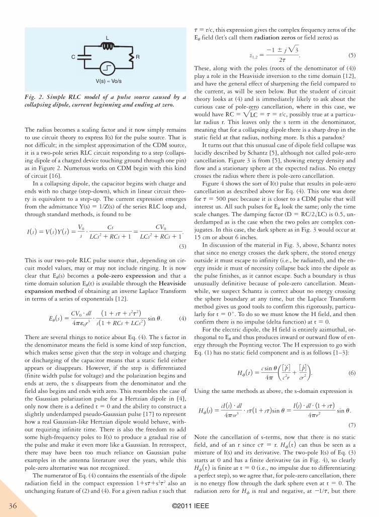
36 ©2011 IEEE
The radius becomes a scaling factor and it now simply remains to use circuit theory to express I(s) for the pulse source. That is not difficult; in the simplest approximation of the CDM source, it is a two-pole series RLC circuit responding to a step (collaps-ing dipole of a charged device touching ground through one pin) as in Figure 2. Numerous works on CDM begin with this kind of circuit [16].
In a collapsing dipole, the capacitor begins with charge and ends with no charge (step-down), which in linear circuit theo-ry is equivalent to a step-up. The current expression emerges from the admittance Y(s) 5 1/Z(s) of the series RLC loop and, through standard methods, is found to be
I 1 s 2 5 V 1 s 2Y 1 s 2 5V0
s# Cs
LCs2 1 RCs 1 15
CV0
LCs2 1 RCs 1 1.
(3)
This is our two-pole RLC pulse source that, depending on cir-cuit model values, may or may not include ringing. It is now clear that Eu(s) becomes a pole-zero expression and that a time domain solution Eu(t) is available through the Heaviside expansion method of obtaining an inverse Laplace Transform in terms of a series of exponentials [12].
Eu 1 s 2 5CV0
# dl
4pe0r3# 11 1 st 1 s2t2 2s 11 1 RCs 1 LCs2 2 sin u. (4)
There are several things to notice about Eq. (4). The s factor in the denominator means the field is some kind of step function, which makes sense given that the step in voltage and charging or discharging of the capacitor means that a static field either appears or disappears. However, if the step is differentiated (finite width pulse for voltage) and the polarization begins and ends at zero, the s disappears from the denominator and the field also begins and ends with zero. This resembles the case of the Gaussian polarization pulse for a Hertzian dipole in [4], only now there is a defined t 5 0 and the ability to construct a slightly underdamped pseudo-Gaussian pulse [17] to represent how a real Gaussian-like Hertzian dipole would behave, with-out requiring infinite time. There is also the freedom to add some high-frequency poles to I(s) to produce a gradual rise of the pulse and make it even more like a Gaussian. In retrospect, there may have been too much reliance on Gaussian pulse examples in the antenna literature over the years, while this pole-zero alternative was not recognized.
The numerator of Eq. (4) contains the essentials of the dipole radiation field in the compact expression 11st1s2t2
, also an
unchanging feature of (2) and (4). For a given radius r such that
t 5 r/c, this expression gives the complex frequency zeros of the Eu field (let’s call them radiation zeros or field zeros) as
z1,2 521 6 j "3
2t. (5)
These, along with the poles (roots of the denominator of (4)) play a role in the Heaviside inversion to the time domain [12], and have the general effect of sharpening the field compared to the current, as will be seen below. But the student of circuit theory looks at (4) and is immediately likely to ask about the curious case of pole-zero cancellation, where in this case, we would have RC 5 "LC 5 t 5 r/c, possibly true at a particu-lar radius r. This leaves only the s term in the denominator, meaning that for a collapsing dipole there is a sharp drop in the static field at that radius, nothing more. Is this a paradox?
It turns out that this unusual case of dipole field collapse was lucidly described by Schantz [5], although not called pole-zero cancellation. Figure 3 is from [5], showing energy density and flow and a stationary sphere at the expected radius. No energy crosses the radius where there is pole-zero cancellation.
Figure 4 shows the sort of I(t) pulse that results in pole-zero cancellation as described above for Eq. (4). This one was done for t 5 500 psec because it is closer to a CDM pulse that will interest us. All such pulses for Eu look the same; only the time scale changes. The damping factor (D 5 RC/2!LC) is 0.5, un-derdamped as is the case when the two poles are complex con-jugates. In this case, the dark sphere as in Fig. 3 would occur at 15 cm or about 6 inches.
In discussion of the material in Fig. 3, above, Schantz notes that since no energy crosses the dark sphere, the stored energy outside it must escape to infinity (i.e., be radiated), and the en-ergy inside it must of necessity collapse back into the dipole as the pulse finishes, as it cannot escape. Such a boundary is thus unusually definitive because of pole-zero cancellation. Mean-while, we suspect Schantz is correct about no energy crossing the sphere boundary at any time, but the Laplace Transform method gives us good tools to confirm this rigorously, particu-larly for t 5 01. To do so we must know the H field, and then confirm there is no impulse (delta function) at t 5 0.
For the electric dipole, the H field is entirely azimuthal, or-thogonal to Eu and thus produces inward or outward flow of en-ergy through the Poynting vector. The H expression to go with Eq. (1) has no static field component and is as follows [1–3]:
Hf 1 t 2 5c sin u
4pa 3 p$ 4
c2r13 p# 4cr2b . (6)
Using the same methods as above, the s-domain expression is
Hf 1s2 5cI 1s2 # dl
4psr3# st 111 st2 sin u 5
I 1s2 # dl # 111 st24pr2 sin u.
(7)
Note the cancellation of s-terms, now that there is no static field, and of an r since ct 5 r. Hf 1 t 2 can thus be seen as a mixture of I(s) and its derivative. The two-pole I(s) of Eq. (3) starts at 0 and has a finite derivative (as in Fig. 4), so clearly Hf 1 t 2 is finite at t 5 0 (i.e., no impulse due to differentiating a perfect step), so we agree that, for pole-zero cancellation, there is no energy flow through the dark sphere even at t 5 0. The radiation zero for Hf is real and negative, at 21/t, but there
L
RC
V(s) ≈ Vo/s
Fig. 2. Simple RLC model of a pulse source caused by a collapsing dipole, current beginning and ending at zero.
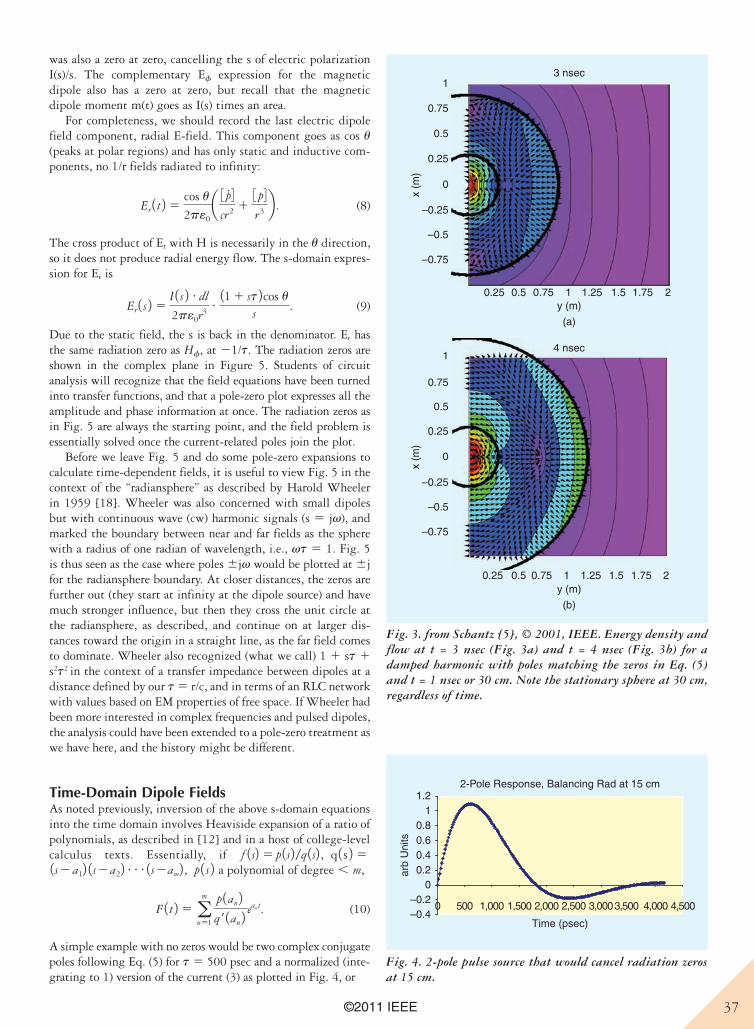
37©2011 IEEE
was also a zero at zero, cancelling the s of electric polarization I(s)/s. The complementary Ef expression for the magnetic dipole also has a zero at zero, but recall that the magnetic dipole moment m(t) goes as I(s) times an area.
For completeness, we should record the last electric dipole field component, radial E-field. This component goes as cos u(peaks at polar regions) and has only static and inductive com-ponents, no 1/r fields radiated to infinity:
Er 1 t 2 5cos u
2pe0a 3 p
# 4cr2 1
3 p4r3 b . (8)
The cross product of Er with H is necessarily in the u direction, so it does not produce radial energy flow. The s-domain expres-sion for Er is
Er 1 s 2 5I 1 s 2 # dl
2pe0r3# 11 1 st 2cos u
s. (9)
Due to the static field, the s is back in the denominator. Er has the same radiation zero as Hf, at 21/t. The radiation zeros are shown in the complex plane in Figure 5. Students of circuit analysis will recognize that the field equations have been turned into transfer functions, and that a pole-zero plot expresses all the amplitude and phase information at once. The radiation zeros as in Fig. 5 are always the starting point, and the field problem is essentially solved once the current-related poles join the plot.
Before we leave Fig. 5 and do some pole-zero expansions to calculate time-dependent fields, it is useful to view Fig. 5 in the context of the “radiansphere” as described by Harold Wheeler in 1959 [18]. Wheeler was also concerned with small dipoles but with continuous wave (cw) harmonic signals (s 5 jv), and marked the boundary between near and far fields as the sphere with a radius of one radian of wavelength, i.e., vt 5 1. Fig. 5 is thus seen as the case where poles 6jv would be plotted at 6j for the radiansphere boundary. At closer distances, the zeros are further out (they start at infinity at the dipole source) and have much stronger influence, but then they cross the unit circle at the radiansphere, as described, and continue on at larger dis-tances toward the origin in a straight line, as the far field comes to dominate. Wheeler also recognized (what we call) 1 1 st 1 s2t2
in the context of a transfer impedance between dipoles at a
distance defined by our t 5 r/c, and in terms of an RLC network with values based on EM properties of free space. If Wheeler had been more interested in complex frequencies and pulsed dipoles, the analysis could have been extended to a pole-zero treatment as we have here, and the history might be different.
Time-Domain Dipole FieldsAs noted previously, inversion of the above s-domain equations into the time domain involves Heaviside expansion of a ratio of polynomials, as described in [12] and in a host of college-level calculus texts. Essentially, if f 1s2 5 p 1s2 /q 1s2 , q 1 s 2 51s2 a12 1s2a22c1s2am2 , p 1 s 2 a polynomial of degree , m,
F 1 t 2 5 am
n51
p 1an 2q r 1an 2 e
ant. (10)
A simple example with no zeros would be two complex conjugate poles following Eq. (5) for t 5 500 psec and a normalized (inte-grating to 1) version of the current (3) as plotted in Fig. 4, or
x (m
)
1
0.75
0.5
0.25
0
–0.25
–0.5
–0.75
0.25 0.5 0.75 1 1.25 1.5 1.75 2y (m)
3 nsec
x (m
)
1
0.75
0.5
0.25
0
–0.25
–0.5
–0.75
0.25 0.5 0.75 1 1.25 1.5 1.75 2y (m)
(a)
(b)
4 nsec
Fig. 3. from Schantz [5], © 2001, IEEE. Energy density and flow at t = 3 nsec (Fig. 3a) and t = 4 nsec (Fig. 3b) for a damped harmonic with poles matching the zeros in Eq. (5) and t = 1 nsec or 30 cm. Note the stationary sphere at 30 cm, regardless of time.
2-Pole Response, Balancing Rad at 15 cm
–0.4–0.2
00.20.40.60.8
11.2
0 500 1,000 1,500 2,000 2,500 3,0003,500 4,000 4,500
Time (psec)
arb
Uni
ts
Fig. 4. 2-pole pulse source that would cancel radiation zeros at 15 cm.
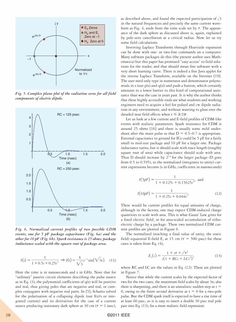
38 ©2011 IEEE
I 1s2 51
110.5s10.25s2 1 I 1t25 4
"3e2t sin 1"3t 2 . (11)
Here the time is in nanoseconds and s in GHz. Note that for “ordinary” passive circuit elements describing the pulse source as in Eq. (3), the polynomial coefficients of q(s) will be positive and real, thus giving poles that are negative and real, or com-plex conjugates with negative real parts. In [5], Schantz solved for the polarization of a collapsing dipole (our I(s)/s or inte-grated current) and its derivatives for the case of a current source producing stationary dark sphere at 30 cm (t 5 1 nsec),
as described above, and found the expected participation of !3 in the natural frequencies and precisely the same current wave-form as Fig. 4, aside from the time scale set by t. The appear-ance of the dark sphere as discussed above is, again, explained by pole-zero cancellation at a critical radius. Now let us try some field calculations.
Inverting Laplace Transforms through Heaviside expansion can be done with one- or two-line commands on a computer. Many software packages do this (the present author uses Math-ematica) but this paper has promised “easy access” to field solu-tions for the reader, and that should mean free software with a very short learning curve. There is indeed a free Java applet for the inverse Laplace Transform, available on the Internet [19]. The user need only type in numerator and denominator polyno-mials in s (our p(s) and q(s)) and push a button, which certainly amounts to a lower barrier to this kind of computational assis-tance than was the case in years past. It is why the author thinks that these highly accessible tools are what students and working engineers need to acquire a feel for pulsed and cw dipole radia-tion in any environment, and without wanting to gloss over the dreaded near field effects when r # l/2p.
Let us look at a few current and E-field profiles of CDM-like events with realistic parameters. Spark resistance for CDM is around 25 ohms [16] and there is usually some mild under-shoot after the main pulse so that D 5 0.5–0.7 is appropriate. External capacitance to ground for ICs could be 5 pF for a fairly small to mid-size package and 10 pF for a larger one. Package inductance varies, but it should scale with trace length (roughly square root of area) while capacitance should scale with area. Thus D should increase by 21/4
for the larger package (D goes
from 0.5 to 0.595), so the normalized (integrates to unity) cur-rent expressions become (s in GHz, coefficients in nanoseconds)
I 15pF 2 51
1 1 0.125s 1 0.15625s2, and
I 110pF2 51
1 1 0.25s 1 0.044s2. (12)
These would be current profiles for equal amounts of charge, although in the factory, one may expect CDM-induced charge quantities to scale with area. This is what Gauss’ Law gives for a fixed electric field, or for area-scaled accumulation of tribo-electric charge by a package. These two normalized CDM cur-rent profiles are plotted in Figure 6.
The normalized (reaching a final value of unity, the static field) equatorial E-field Ez at 15 cm (t 5 500 psec) for these cases is taken from Eq. (4),
Ez 1 s 2 51 1 st 1 s2t2
s 11 1 RCs 1 LCs2 2 , (13)
where RC and LC are the values in Eq. (12). These are plotted in Figure 7.
Notice that while the current scales by the expected factor of two for the two cases, the maximum field scales by about 3x; also there is sharpening, and there is an unrealistic sudden step at t 5 0, owing to the finite second derivative at t 5 0 for a two-pole pulse. But the CDM spark itself is expected to have a rise time of at least 60 psec, so it is easy to insert a double 30 psec real pole pair into Eq. (13), for a more realistic field expression:
j y
x
e j 4π /3
e j 2π /3
–1
Normalizedto 1/τ
Eθ Zeros
Hφ and ErZero at –1 Hφ Zero at 0
Fig. 5. Complex plane plot of the radiation zeros for all field components of electric dipole.
0.5
1.0
1.5
2.0
0.5 1.0 1.5 2.0
1
2
3
4
Time (nsec)
0.5 1.0 1.5 2.0Time (nsec)
(a)
(b)
RC = 125 psec
RC = 250 psec
Fig. 6. Normalized current profiles of two possible CDM events, one for 5 pF package capacitance (Fig. 6a) and the other for 10 pF (Fig. 6b). Spark resistance is 25 ohms; package inductance scaled with the square root of package area.
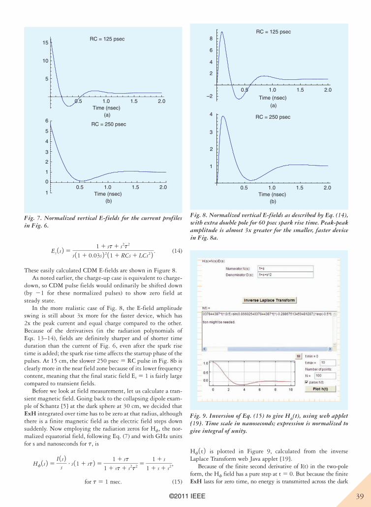
39©2011 IEEE
Ez 1 s 2 51 1 st 1 s2t2
s 11 1 0.03s 2 2 11 1 RCs 1 LCs2 2 . (14)
These easily calculated CDM E-fields are shown in Figure 8. As noted earlier, the charge-up case is equivalent to charge-
down, so CDM pulse fields would ordinarily be shifted down (by 21 for these normalized pulses) to show zero field at steady state.
In the more realistic case of Fig. 8, the E-field amplitude swing is still about 3x more for the faster device, which has 2x the peak current and equal charge compared to the other. Because of the derivatives (in the radiation polynomials of Eqs. 13–14), fields are definitely sharper and of shorter time duration than the current of Fig. 6, even after the spark rise time is added; the spark rise time affects the startup phase of the pulses. At 15 cm, the slower 250 psec 5 RC pulse in Fig. 8b is clearly more in the near field zone because of its lower frequency content, meaning that the final static field Ez 5 1 is fairly large compared to transient fields.
Before we look at field measurement, let us calculate a tran-sient magnetic field. Going back to the collapsing dipole exam-ple of Schantz [5] at the dark sphere at 30 cm, we decided that ExH integrated over time has to be zero at that radius, although there is a finite magnetic field as the electric field steps down suddenly. Now employing the radiation zeros for Hf, the nor-malized equatorial field, following Eq. (7) and with GHz units for s and nanoseconds for t, is
Hf 1 s 2 5I 1 s 2
s# s 11 1 st 2 5
1 1 st
1 1 st 1 s2t2 51 1 s
1 1 s 1 s2,
for t 5 1 nsec. (15)
Hf 1 t 2 is plotted in Figure 9, calculated from the inverse Laplace Transform web Java applet [19].
Because of the finite second derivative of I(t) in the two-pole form, the Hf field has a pure step at t 5 0. But because the finite ExH lasts for zero time, no energy is transmitted across the dark
6
5
4
3
2
1
0
1
0.5 1.0 1.5 2.0
5
10
15
Time (nsec)
0.5 1.0 1.5 2.0Time (nsec)
(a)
(b)
RC = 125 psec
RC = 250 psec
Fig. 7. Normalized vertical E-fields for the current profiles in Fig. 6.
4
3
2
1
0.5 1.0 1.5 2.0
4
2
–2
6
8
Time (nsec)
0.5 1.0 1.5 2.0Time (nsec)
(a)
(b)
RC = 125 psec
RC = 250 psec
Fig. 8. Normalized vertical E-fields as described by Eq. (14), with extra double pole for 60 psec spark rise time. Peak-peak amplitude is almost 3x greater for the smaller, faster device in Fig. 8a.
Fig. 9. Inversion of Eq. (15) to give Hf(t), using web applet
[19]. Time scale in nanoseconds; expression is normalized to give integral of unity.
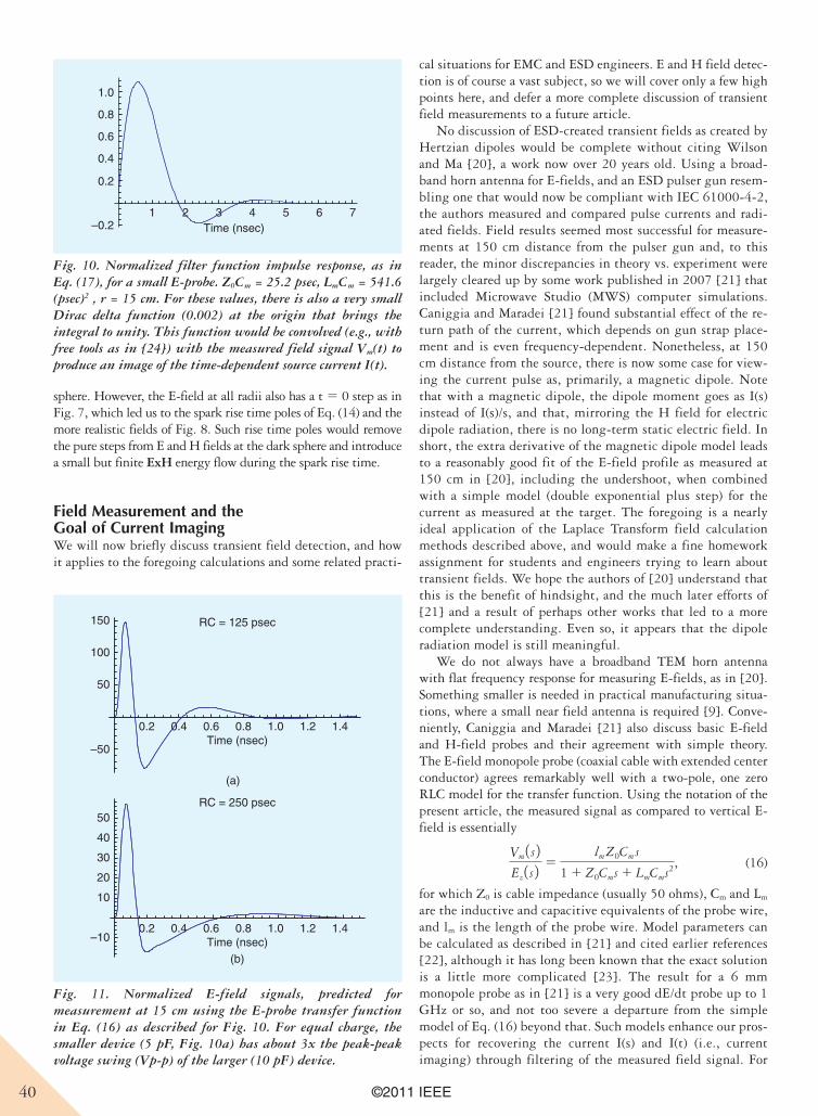
40 ©2011 IEEE
sphere. However, the E-field at all radii also has a t 5 0 step as in Fig. 7, which led us to the spark rise time poles of Eq. (14) and the more realistic fields of Fig. 8. Such rise time poles would remove the pure steps from E and H fields at the dark sphere and introduce a small but finite ExH energy flow during the spark rise time.
Field Measurement and the Goal of Current ImagingWe will now briefly discuss transient field detection, and how it applies to the foregoing calculations and some related practi-
cal situations for EMC and ESD engineers. E and H field detec-tion is of course a vast subject, so we will cover only a few high points here, and defer a more complete discussion of transient field measurements to a future article.
No discussion of ESD-created transient fields as created by Hertzian dipoles would be complete without citing Wilson and Ma [20], a work now over 20 years old. Using a broad-band horn antenna for E-fields, and an ESD pulser gun resem-bling one that would now be compliant with IEC 61000-4-2, the authors measured and compared pulse currents and radi-ated fields. Field results seemed most successful for measure-ments at 150 cm distance from the pulser gun and, to this reader, the minor discrepancies in theory vs. experiment were largely cleared up by some work published in 2007 [21] that included Microwave Studio (MWS) computer simulations. Caniggia and Maradei [21] found substantial effect of the re-turn path of the current, which depends on gun strap place-ment and is even frequency-dependent. Nonetheless, at 150 cm distance from the source, there is now some case for view-ing the current pulse as, primarily, a magnetic dipole. Note that with a magnetic dipole, the dipole moment goes as I(s) instead of I(s)/s, and that, mirroring the H field for electric dipole radiation, there is no long-term static electric field. In short, the extra derivative of the magnetic dipole model leads to a reasonably good fit of the E-field profile as measured at 150 cm in [20], including the undershoot, when combined with a simple model (double exponential plus step) for the current as measured at the target. The foregoing is a nearly ideal application of the Laplace Transform field calculation methods described above, and would make a fine homework assignment for students and engineers trying to learn about transient fields. We hope the authors of [20] understand that this is the benefit of hindsight, and the much later efforts of [21] and a result of perhaps other works that led to a more complete understanding. Even so, it appears that the dipole radiation model is still meaningful.
We do not always have a broadband TEM horn antenna with flat frequency response for measuring E-fields, as in [20]. Something smaller is needed in practical manufacturing situa-tions, where a small near field antenna is required [9]. Conve-niently, Caniggia and Maradei [21] also discuss basic E-field and H-field probes and their agreement with simple theory. The E-field monopole probe (coaxial cable with extended center conductor) agrees remarkably well with a two-pole, one zero RLC model for the transfer function. Using the notation of the present article, the measured signal as compared to vertical E-field is essentially
Vm 1 s 2Ez 1 s 2 5
lmZ0Cms
1 1 Z0Cms 1 LmCms2, (16)
for which Z0 is cable impedance (usually 50 ohms), Cm and Lm are the inductive and capacitive equivalents of the probe wire, and lm is the length of the probe wire. Model parameters can be calculated as described in [21] and cited earlier references [22], although it has long been known that the exact solution is a little more complicated [23]. The result for a 6 mm monopole probe as in [21] is a very good dE/dt probe up to 1 GHz or so, and not too severe a departure from the simple model of Eq. (16) beyond that. Such models enhance our pros-pects for recovering the current I(s) and I(t) (i.e., current imaging) through filtering of the measured field signal. For
1 2 3 4 5 6 7–0.2
0.2
0.4
0.6
0.8
1.0
Time (nsec)
Fig. 10. Normalized filter function impulse response, as in Eq. (17), for a small E-probe. Z0Cm = 25.2 psec, LmCm = 541.6 (psec)2 , r = 15 cm. For these values, there is also a very small Dirac delta function (0.002) at the origin that brings the integral to unity. This function would be convolved (e.g., with free tools as in [24]) with the measured field signal Vm(t) to produce an image of the time-dependent source current I(t).
0.2 0.4 0.6 0.8 1.0 1.2 1.4
–50
50
100
150
–10
10
20
30
40
50
Time (nsec)
0.2 0.4 0.6 0.8 1.0 1.2 1.4Time (nsec)
(a)
(b)
RC = 250 psec
RC = 125 psec
Fig. 11. Normalized E-field signals, predicted for measurement at 15 cm using the E-probe transfer function in Eq. (16) as described for Fig. 10. For equal charge, the smaller device (5 pF, Fig. 10a) has about 3x the peak-peak voltage swing (Vp-p) of the larger (10 pF) device.
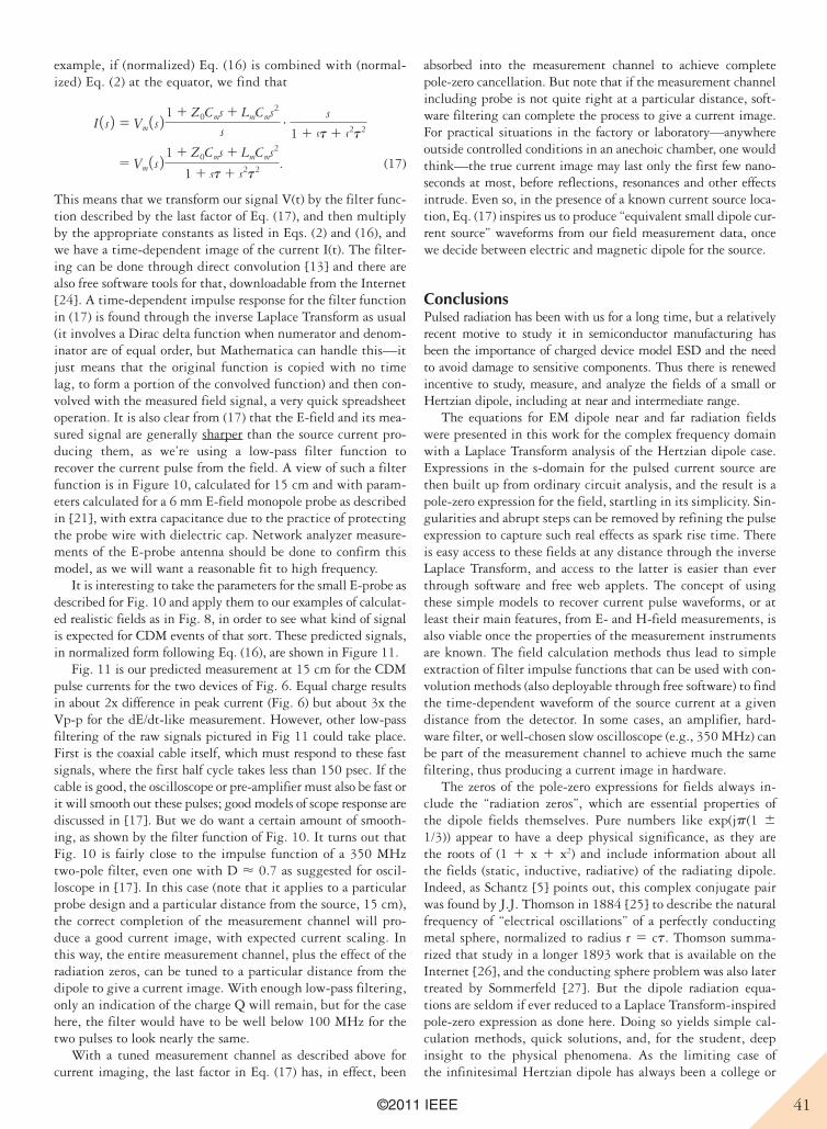
41©2011 IEEE
example, if (normalized) Eq. (16) is combined with (normal-ized) Eq. (2) at the equator, we find that
I 1 s 2 5 Vm 1 s 2 1 1 Z0Cms 1 LmCms2
s# s
1 1 st 1 s2t2
5 Vm 1 s 2 1 1 Z0Cms 1 LmCms2
1 1 st 1 s2t2 . (17)
This means that we transform our signal V(t) by the filter func-tion described by the last factor of Eq. (17), and then multiply by the appropriate constants as listed in Eqs. (2) and (16), and we have a time-dependent image of the current I(t). The filter-ing can be done through direct convolution [13] and there are also free software tools for that, downloadable from the Internet [24]. A time-dependent impulse response for the filter function in (17) is found through the inverse Laplace Transform as usual (it involves a Dirac delta function when numerator and denom-inator are of equal order, but Mathematica can handle this—it just means that the original function is copied with no time lag, to form a portion of the convolved function) and then con-volved with the measured field signal, a very quick spreadsheet operation. It is also clear from (17) that the E-field and its mea-sured signal are generally sharper than the source current pro-ducing them, as we’re using a low-pass filter function to recover the current pulse from the field. A view of such a filter function is in Figure 10, calculated for 15 cm and with param-eters calculated for a 6 mm E-field monopole probe as described in [21], with extra capacitance due to the practice of protecting the probe wire with dielectric cap. Network analyzer measure-ments of the E-probe antenna should be done to confirm this model, as we will want a reasonable fit to high frequency.
It is interesting to take the parameters for the small E-probe as described for Fig. 10 and apply them to our examples of calculat-ed realistic fields as in Fig. 8, in order to see what kind of signal is expected for CDM events of that sort. These predicted signals, in normalized form following Eq. (16), are shown in Figure 11.
Fig. 11 is our predicted measurement at 15 cm for the CDM pulse currents for the two devices of Fig. 6. Equal charge results in about 2x difference in peak current (Fig. 6) but about 3x the Vp-p for the dE/dt-like measurement. However, other low-pass filtering of the raw signals pictured in Fig 11 could take place. First is the coaxial cable itself, which must respond to these fast signals, where the first half cycle takes less than 150 psec. If the cable is good, the oscilloscope or pre-amplifier must also be fast or it will smooth out these pulses; good models of scope response are discussed in [17]. But we do want a certain amount of smooth-ing, as shown by the filter function of Fig. 10. It turns out that Fig. 10 is fairly close to the impulse function of a 350 MHz two-pole filter, even one with D < 0.7 as suggested for oscil-loscope in [17]. In this case (note that it applies to a particular probe design and a particular distance from the source, 15 cm), the correct completion of the measurement channel will pro-duce a good current image, with expected current scaling. In this way, the entire measurement channel, plus the effect of the radiation zeros, can be tuned to a particular distance from the dipole to give a current image. With enough low-pass filtering, only an indication of the charge Q will remain, but for the case here, the filter would have to be well below 100 MHz for the two pulses to look nearly the same.
With a tuned measurement channel as described above for current imaging, the last factor in Eq. (17) has, in effect, been
absorbed into the measurement channel to achieve complete pole-zero cancellation. But note that if the measurement channel including probe is not quite right at a particular distance, soft-ware filtering can complete the process to give a current image. For practical situations in the factory or laboratory—anywhere outside controlled conditions in an anechoic chamber, one would think—the true current image may last only the first few nano-seconds at most, before reflections, resonances and other effects intrude. Even so, in the presence of a known current source loca-tion, Eq. (17) inspires us to produce “equivalent small dipole cur-rent source” waveforms from our field measurement data, once we decide between electric and magnetic dipole for the source.
ConclusionsPulsed radiation has been with us for a long time, but a relatively recent motive to study it in semiconductor manufacturing has been the importance of charged device model ESD and the need to avoid damage to sensitive components. Thus there is renewed incentive to study, measure, and analyze the fields of a small or Hertzian dipole, including at near and intermediate range.
The equations for EM dipole near and far radiation fields were presented in this work for the complex frequency domain with a Laplace Transform analysis of the Hertzian dipole case. Expressions in the s-domain for the pulsed current source are then built up from ordinary circuit analysis, and the result is a pole-zero expression for the field, startling in its simplicity. Sin-gularities and abrupt steps can be removed by refining the pulse expression to capture such real effects as spark rise time. There is easy access to these fields at any distance through the inverse Laplace Transform, and access to the latter is easier than ever through software and free web applets. The concept of using these simple models to recover current pulse waveforms, or at least their main features, from E- and H-field measurements, is also viable once the properties of the measurement instruments are known. The field calculation methods thus lead to simple extraction of filter impulse functions that can be used with con-volution methods (also deployable through free software) to find the time-dependent waveform of the source current at a given distance from the detector. In some cases, an amplifier, hard-ware filter, or well-chosen slow oscilloscope (e.g., 350 MHz) can be part of the measurement channel to achieve much the same filtering, thus producing a current image in hardware.
The zeros of the pole-zero expressions for fields always in-clude the “radiation zeros”, which are essential properties of the dipole fields themselves. Pure numbers like exp(jp(1 6 1/3)) appear to have a deep physical significance, as they are the roots of (1 1 x 1 x2) and include information about all the fields (static, inductive, radiative) of the radiating dipole. Indeed, as Schantz [5] points out, this complex conjugate pair was found by J.J. Thomson in 1884 [25] to describe the natural frequency of “electrical oscillations” of a perfectly conducting metal sphere, normalized to radius r 5 ct. Thomson summa-rized that study in a longer 1893 work that is available on the Internet [26], and the conducting sphere problem was also later treated by Sommerfeld [27]. But the dipole radiation equa-tions are seldom if ever reduced to a Laplace Transform-inspired pole-zero expression as done here. Doing so yields simple cal-culation methods, quick solutions, and, for the student, deep insight to the physical phenomena. As the limiting case of the infinitesimal Hertzian dipole has always been a college or
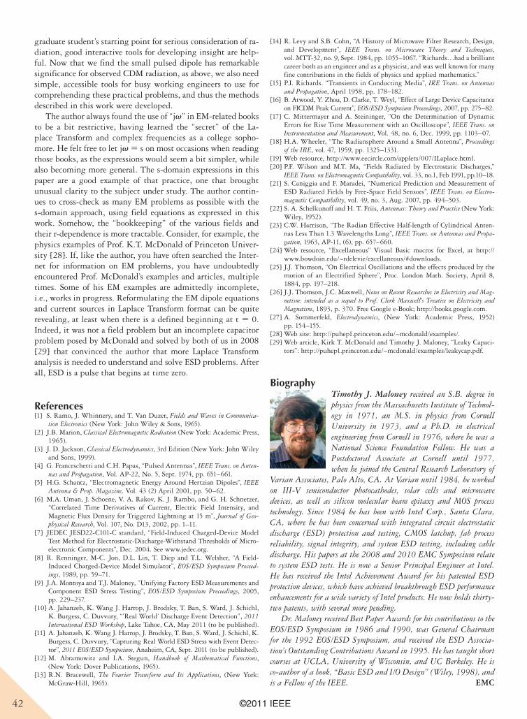
42 ©2011 IEEE
graduate student’s starting point for serious consideration of ra-diation, good interactive tools for developing insight are help-ful. Now that we find the small pulsed dipole has remarkable significance for observed CDM radiation, as above, we also need simple, accessible tools for busy working engineers to use for comprehending these practical problems, and thus the methods described in this work were developed.
The author always found the use of “jv” in EM-related books to be a bit restrictive, having learned the “secret” of the La-place Transform and complex frequencies as a college sopho-more. He felt free to let jv 5 s on most occasions when reading those books, as the expressions would seem a bit simpler, while also becoming more general. The s-domain expressions in this paper are a good example of that practice, one that brought unusual clarity to the subject under study. The author contin-ues to cross-check as many EM problems as possible with the s-domain approach, using field equations as expressed in this work. Somehow, the “bookkeeping” of the various fields and their r-dependence is more tractable. Consider, for example, the physics examples of Prof. K.T. McDonald of Princeton Univer-sity [28]. If, like the author, you have often searched the Inter-net for information on EM problems, you have undoubtedly encountered Prof. McDonald’s examples and articles, multiple times. Some of his EM examples are admittedly incomplete, i.e., works in progress. Reformulating the EM dipole equations and current sources in Laplace Transform format can be quite revealing, at least when there is a defined beginning at t 5 0. Indeed, it was not a field problem but an incomplete capacitor problem posed by McDonald and solved by both of us in 2008 [29] that convinced the author that more Laplace Transform analysis is needed to understand and solve ESD problems. After all, ESD is a pulse that begins at time zero.
References[1] S. Ramo, J. Whinnery, and T. Van Duzer, Fields and Waves in Communica-
tion Electronics (New York: John Wiley & Sons, 1965).[2] J.B. Marion, Classical Electromagnetic Radiation (New York: Academic Press,
1965).[3] J. D. Jackson, Classical Electrodynamics, 3rd Edition (New York: John Wiley
and Sons, 1999).[4] G. Franceschetti and C.H. Papas, “Pulsed Antennas”, IEEE Trans. on Anten-
nas and Propagation, Vol. AP-22, No. 5, Sept. 1974, pp. 651–661. [5] H.G. Schantz, “Electromagnetic Energy Around Hertzian Dipoles”, IEEE
Antenna & Prop. Magazine, Vol. 43 (2) April 2001, pp. 50–62.[6] M.A. Uman, J. Schoene, V. A. Rakov, K. J. Rambo, and G. H. Schnetzer,
“Correlated Time Derivatives of Current, Electric Field Intensity, and Magnetic Flux Density for Triggered Lightning at 15 m”, Journal of Geo-physical Research, Vol. 107, No. D13, 2002, pp. 1–11.
[7] JEDEC JESD22-C101-C standard, “Field-Induced Charged-Device Model Test Method for Electrostatic-Discharge-Withstand Thresholds of Micro-electronic Components”, Dec. 2004. See www.jedec.org.
[8] R. Renninger, M-C. Jon, D.L. Lin, T. Diep and T.L. Welsher, “A Field-Induced Charged-Device Model Simulator”, EOS/ESD Symposium Proceed-ings, 1989, pp. 59–71.
[9] J.A. Montoya and T.J. Maloney, “Unifying Factory ESD Measurements and Component ESD Stress Testing”, EOS/ESD Symposium Proceedings, 2005, pp. 229–237.
[10] A. Jahanzeb, K. Wang J. Harrop, J. Brodsky, T. Ban, S. Ward, J. Schichl, K. Burgess, C. Duvvury, “’Real World’ Discharge Event Detection”, 2011 International ESD Workshop, Lake Tahoe, CA, May 2011 (to be published).
[11] A. Jahanzeb, K. Wang J. Harrop, J. Brodsky, T. Ban, S. Ward, J. Schichl, K. Burgess, C. Duvvury, “Capturing Real World ESD Stress with Event Detec-tor”, 2011 EOS/ESD Symposium, Anaheim, CA, Sept. 2011 (to be published).
[12] M. Abramowitz and I.A. Stegun, Handbook of Mathematical Functions, (New York: Dover Publications, 1965).
[13] R.N. Bracewell, The Fourier Transform and Its Applications, (New York: McGraw-Hill, 1965).
[14] R. Levy and S.B. Cohn, “A History of Microwave Filter Research, Design, and Development”, IEEE Trans. on Microwave Theory and Techniques, vol. MTT-32, no. 9, Sept. 1984, pp. 1055–1067. “Richards…had a brilliant career both as an engineer and as a physicist, and was well known for many fine contributions in the fields of physics and applied mathematics.”
[15] P.I. Richards. “Transients in Conducting Media”, IRE Trans. on Antennas and Propagation, April 1958, pp. 178–182.
[16] B. Atwood, Y. Zhou, D. Clarke, T. Weyl, “Effect of Large Device Capacitance on FICDM Peak Current”, EOS/ESD Symposium Proceedings, 2007, pp. 275–82.
[17] C. Mittermayer and A. Steininger, “On the Determination of Dynamic Errors for Rise Time Measurement with an Oscilloscope”, IEEE Trans. on Instrumentation and Measurement, Vol. 48, no. 6, Dec. 1999, pp. 1103–07.
[18] H.A. Wheeler, “The Radiansphere Around a Small Antenna”, Proceedings of the IRE, vol. 47, 1959, pp. 1325–1331.
[19] Web resource, http://www.eecircle.com/applets/007/ILaplace.html.[20] P.F. Wilson and M.T. Ma, “Fields Radiated by Electrostatic Discharges,”
IEEE Trans. on Electromagnetic Compatibility, vol. 33, no.1, Feb 1991, pp.10–18.[21] S. Caniggia and F. Maradei, “Numerical Prediction and Measurement of
ESD Radiated Fields by Free-Space Field Sensors”, IEEE Trans. on Electro-magnetic Compatibility, vol. 49, no. 3, Aug. 2007, pp. 494–503.
[22] S. A. Schelkunoff and H. T. Friis, Antennas: Theory and Practice (New York: Wiley, 1952).
[23] C.W. Harrison, “The Radian Effective Half-length of Cylindrical Anten-nas Less Than 1.3 Wavelengths Long”, IEEE Trans. on Antennas and Propa-gation, 1963, AP-11, (6), pp. 657–660.
[24] Web resource, “Excellaneous” Visual Basic macros for Excel, at http://www.bowdoin.edu/~rdelevie/excellaneous/#downloads.
[25] J.J. Thomson, “On Electrical Oscillations and the effects produced by the motion of an Electrified Sphere”, Proc. London Math. Society, April 8, 1884, pp. 197–218.
[26] J.J. Thomson, J.C. Maxwell, Notes on Recent Researches in Electricity and Mag-netism: intended as a sequel to Prof. Clerk Maxwell’s Treatise on Electricity and Magnetism, 1893, p. 370. Free Google e-Book; http://books.google.com.
[27] A. Sommerfeld, Electrodynamics, (New York: Academic Press, 1952) pp. 154–155.
[28] Web site: http://puhep1.princeton.edu/~mcdonald/examples/. [29] Web article, Kirk T. McDonald and Timothy J. Maloney, “Leaky Capaci-
tors”: http://puhep1.princeton.edu/~mcdonald/examples/leakycap.pdf.
BiographyTimothy J. Maloney received an S.B. degree in physics from the Massachusetts Institute of Technol-ogy in 1971, an M.S. in physics from Cornell University in 1973, and a Ph.D. in electrical engineering from Cornell in 1976, where he was a National Science Foundation Fellow. He was a Postdoctoral Associate at Cornell until 1977, when he joined the Central Research Laboratory of
Varian Associates, Palo Alto, CA. At Varian until 1984, he worked on III-V semiconductor photocathodes, solar cells and microwave devices, as well as silicon molecular beam epitaxy and MOS process technology. Since 1984 he has been with Intel Corp., Santa Clara, CA, where he has been concerned with integrated circuit electrostatic discharge (ESD) protection and testing, CMOS latchup, fab process reliability, signal integrity, and system ESD testing, including cable discharge. His papers at the 2008 and 2010 EMC Symposium relate to system ESD tests. He is now a Senior Principal Engineer at Intel. He has received the Intel Achievement Award for his patented ESD protection devices, which have achieved breakthrough ESD performance enhancements for a wide variety of Intel products. He now holds thirty-two patents, with several more pending.
Dr. Maloney received Best Paper Awards for his contributions to the EOS/ESD Symposium in 1986 and 1990, was General Chairman for the 1992 EOS/ESD Symposium, and received the ESD Associa-tion’s Outstanding Contributions Award in 1995. He has taught short courses at UCLA, University of Wisconsin, and UC Berkeley. He is co-author of a book, “Basic ESD and I/O Design” (Wiley, 1998), and is a Fellow of the IEEE. EMC
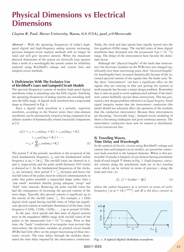
43©2011 IEEE
Physical Dimensions vs Electrical DimensionsClayton R. Paul, Mercer University, Macon, GA (USA), [email protected]
Abstract – With the operating frequencies of today’s high-speed digital and high-frequency analog systems increasing, previous lumped-circuit analysis methods will no longer be valid and will give incorrect answers. When the maximum physical dimensions of the system are electrically large (greater than a tenth of a wavelength) the system cannot be reliability analyzed using Kirchhoff’s voltage and current laws and lumped-circuit methods.
I. Deficiencies With The Exclusive Use of Kirchhoff’s Laws and Lumped-Circuit ModelsThe spectral (frequency) content of modern high-speed digital waveforms today is extending into the GHz regime. Similarly, the operating frequencies of analog systems are extending well into the GHz range. A digital clock waveform has a trapezoidal shape as illustrated in Fig. 1:
Since a digital clock waveform is a periodic, repetitive waveform, according to the Fourier series their time-domain waveforms can be alternatively viewed as being composed of an infinite number of harmonically related sinusoidal components as [1]
x 1 t 2 5 c0 1 c1 cos 1v0t 1 u12 1 c2 cos 12v0t 1u221 c3 cos 13v0t 1 u32 1c
5 c0 1a`
n51
cn cos1nv0t1un2 (1)
The period T of the periodic waveform is the reciprocal of the clock fundamental frequency, f0, and the fundamental radian frequency is v0 5 2p f0. The rise/fall times are denoted as tr
and tf, respectively, and the pulse width (between 50% levels) is denoted as t. As the fundamental frequencies of the clocks, f0, are increased, their period T 5 1@f0
decreases and hence the rise/fall times of the pulses must be reduced commensurately in order that pulses resemble a trapezoidal shape rather than a “saw tooth” waveform thereby giving adequate “setup” and “hold” time intervals. Reducing the pulse rise/fall times has had the consequence of increasing the spectral content of the wave shape. Typically this spectral content is significant up to the inverse of the rise/fall times, 1@tr
. For example, a 1 GHz digital clock signal having rise/fall times of 100ps has signifi-cant spectral content at multiples (harmonics) of the basic clock frequency (1 GHz, 2 GHz, 3 GHz, …..) up to around 10 GHz.
In the past, clock speeds and data rates of digital systems were in the megahertz (MHz) range with rise/fall times of the pulses in the nanosecond (1ns 5 1029s) range. Prior to that time, the “lands” (conductors of rectangular cross section) that interconnect the electronic modules on printed circuit boards (PCBs) had little effect on the proper functioning of those elec-tronic circuits. The time delays through the modules domi-nated the time delay imposed by the interconnect conductors.
Today, the clock and data speeds have rapidly moved into the low gigahertz (GHz) range. The rise/fall times of those digital waveforms have decreased into the picosecond (1ps 5 10212s) range. The delays of the interconnects have become the domi-nant factor.
Although the “physical lengths” of the lands that intercon-nect the electronic modules on the PCBs have not changed sig-nificantly over these intervening years, their “electrical lengths” (in wavelengths) have increased dramatically because of the in-creased spectral content of the signals that the lands carry. To-day these “interconnects” can have a significant effect on the signals they are carrying so that just getting the systems to work properly has become a major design problem. Remember that it does no good to write sophisticated software if the hard-ware cannot faithfully execute those instructions. This has gen-erated a new design problem referred to as Signal Integrity. Good signal integrity means that the interconnect conductors (the lands) should not adversely affect the operation of the modules that the conductors interconnect. Because these interconnects are becoming “electrically long”, lumped-circuit modeling of them is becoming inadequate and gives erroneous answers. The interconnect conductors must now be treated as distributed-circuit transmission lines.
II. Traveling Waves, Time Delay and WavelengthIn the analysis of electric circuits using Kirchhoff’s voltage and current laws and lumped-circuit models, we ignored the connec-tion leads attached to the lumped elements. When is this per-missible? Consider a lumped-circuit element having attachment leads of total length l shown in Fig. 2. Single-frequency, sinusoi-dal currents along the attachment leads are in fact traveling waves which can be written in terms of position z along the leads and time t as
i 1 t, z 2 5 Icos 1vt 2 bz 2 (2)
where the radian frequency v is written in terms of cyclic frequency f as v 5 2p f radians@s and b is the phase constant in
x (t )
A
2A
τr τf 1f0
T =t
τ
Fig. 1. A typical digital clock/data waveform.
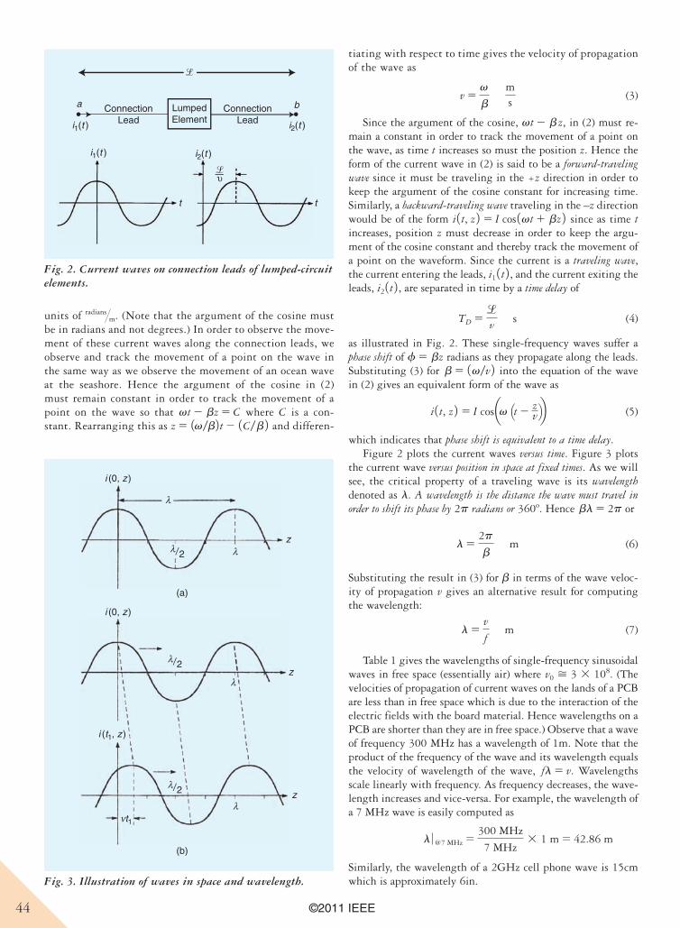
44 ©2011 IEEE
units of radians@m. (Note that the argument of the cosine must be in radians and not degrees.) In order to observe the move-ment of these current waves along the connection leads, we observe and track the movement of a point on the wave in the same way as we observe the movement of an ocean wave at the seashore. Hence the argument of the cosine in (2) must remain constant in order to track the movement of a point on the wave so that vt 2 bz 5 C where C is a con-stant. Rearranging this as z 5 1v/b2 t 2 1C/b 2 and differen-
tiating with respect to time gives the velocity of propagation of the wave as
v 5v
b
ms
(3)
Since the argument of the cosine, vt 2 bz, in (2) must re-main a constant in order to track the movement of a point on the wave, as time t increases so must the position z. Hence the form of the current wave in (2) is said to be a forward-traveling wave since it must be traveling in the +z direction in order to keep the argument of the cosine constant for increasing time. Similarly, a backward-traveling wave traveling in the –z direction would be of the form i 1 t, z 2 5 I cos 1vt 1 bz 2 since as time t increases, position z must decrease in order to keep the argu-ment of the cosine constant and thereby track the movement of a point on the waveform. Since the current is a traveling wave, the current entering the leads, i1 1 t 2 , and the current exiting the leads, i2 1 t 2 , are separated in time by a time delay of
TD 5lv s (4)
as illustrated in Fig. 2. These single-frequency waves suffer a phase shift of f 5 bz radians as they propagate along the leads. Substituting (3) for b 5 1v/v 2 into the equation of the wave in (2) gives an equivalent form of the wave as
i 1 t, z 2 5 I cosav Qt 2zv Rb (5)
which indicates that phase shift is equivalent to a time delay.Figure 2 plots the current waves versus time. Figure 3 plots
the current wave versus position in space at fixed times. As we will see, the critical property of a traveling wave is its wavelengthdenoted as l. A wavelength is the distance the wave must travel in order to shift its phase by 2p radians or 360o. Hence bl 5 2p or
l 52p
b m (6)
Substituting the result in (3) for b in terms of the wave veloc-ity of propagation v gives an alternative result for computing the wavelength:
l 5v
f m (7)
Table 1 gives the wavelengths of single-frequency sinusoidal waves in free space (essentially air) where v0 > 3 3 108. (The velocities of propagation of current waves on the lands of a PCB are less than in free space which is due to the interaction of the electric fields with the board material. Hence wavelengths on a PCB are shorter than they are in free space.) Observe that a wave of frequency 300 MHz has a wavelength of 1m. Note that the product of the frequency of the wave and its wavelength equals the velocity of wavelength of the wave, fl 5 v. Wavelengths scale linearly with frequency. As frequency decreases, the wave-length increases and vice-versa. For example, the wavelength of a 7 MHz wave is easily computed as
l 0 @7 MHz 5300 MHz
7 MHz3 1 m 5 42.86 m
Similarly, the wavelength of a 2GHz cell phone wave is 15cm which is approximately 6in.
a
i1(t )
i1(t )
i2(t )
i2(t )
ConnectionLead
ConnectionLead
LumpedElement
b
lυ
t t
l
Fig. 2. Current waves on connection leads of lumped-circuit elements.
i (0, z )
i (0, z )
i (t1, z )
νt1
λ
λ
λ
λ
λ 2
λ 2
λ 2
z
z
z
(a)
(b)
Fig. 3. Illustration of waves in space and wavelength.
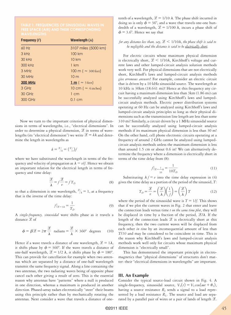
45©2011 IEEE
Now we turn to the important criterion of physical dimen-sions in terms of wavelengths, i.e., “electrical dimensions”. In order to determine a physical dimension, l in terms of wave-lengths (its “electrical dimension”) we write l5 kl and deter-mine the length in wavelengths as
k 5 l@l 5 1l@v 2 fwhere we have substituted the wavelength in terms of the fre-quency and velocity of propagation as l 5 v/f. Hence we obtain an important relation for the electrical length in terms of fre-quency and time delay:
l
l5 f
lv
5 f TD (8)
so that a dimension is one wavelength, l@l 5 1, at a frequency that is the inverse of the time delay:
f 0l51l 51
TD
(9)
A single-frequency, sinusoidal wave shifts phase as it travels a distance l of
f 5 b l5 2p l
l radians 5
l
l3 360o degrees (10)
Hence if a wave travels a distance of one wavelength, l5 1l, it shifts phase by f 5 360o. If the wave travels a distance of one-half wavelength, l5 1/2 l, it shifts phase by f 5 180o. This can provide for cancellation for example when two anten-nas which are separated by a distance of one-half wavelength transmit the same frequency signal. Along a line containing the two antennas, the two radiating waves being of opposite phase cancel each other giving a result of zero. This is the essential reason why antennas have “patterns” where a null is produced in one direction, whereas a maximum is produced in another direction. Phased-array radars electronically “steer” their beams using this principle rather than by mechanically rotating the antennas. Next consider a wave that travels a distance of one-
tenth of a wavelength, l5 1/10 l. The phase shift incurred in doing so is only f 5 36o, and a wave that travels one-one hun-dredth of a wavelength, l5 1/100 l, incurs a phase shift of f 5 3.6o. Hence we say that
for any distance less than, say, l , 1/10l, the phase shift is said to be negligible and the distance is said to be electrically short.
For electric circuits whose maximum physical dimension is electrically short, l , 1/10l, Kirchhoff’s voltage and cur-rent laws and other lumped-circuit analysis solution methods work very well. For physical dimensions that are not electrically short, Kirchhoff’s laws and lumped-circuit analysis methods give erroneous answers! For example, consider an electric circuit that is driven by a 10 kHz sinusoidal source. The wavelength at 10 kHz is 30km (18.641 mi)! Hence at this frequency any cir-cuit having a maximum dimension less than 3km (1.86 mi) can be successfully analyzed using Kirchhoff’s laws and lumped-circuit analysis methods. Electric power distribution systems operating at 60 Hz can be analyzed using Kirchhoff’s laws and lumped-circuit analysis principles so long as their physical di-mensions such as the transmission line length are less than some 310 mi! Similarly, a circuit driven by a 1 MHz sinusoidal source can be successfully analyzed using lumped-circuit analysis methods if its maximum physical dimension is less than 30 m! On the other hand, cell phone electronic circuits operating at a frequency of around 2 GHz cannot be analyzed using lumped-circuit analysis methods unless the maximum dimension is less than around 1.5 cm or about 0.6 in! We can alternatively de-termine the frequency where a dimension is electrically short in terms of the time delay from (8):
f 0l51
10l 5
1
10TD
(11)
Substituting l f 5 v into the time delay expression in (4) gives the time delay as a portion of the period of the sinusoid, T:
TD 5lv
5 allb a1
fb 5 al
lb T (12)
where the period of the sinusoidal wave is T 5 1/f. This shows that if we plot the current waves in Fig. 2 that enter and leave the connection leads versus time t on the same time plot, they will be displaced in time by a fraction of the period, l/l. If the length of the connection leads l is electrically short at this frequency, then the two current waves will be displaced from each other in time by an inconsequential amount of less than T/10 and may be considered to be coincident in time. This is the reason why Kirchhoff’s laws and lumped-circuit analysis methods work well only for circuits whose maximum physical dimension is “electrically small”.
This has demonstrated the important principle in electro-magnetics that “physical dimensions” of structures don’t mat-ter: their “electrical dimensions in wavelengths” are important.
III. An ExampleConsider the typical source-load circuit shown in Fig. 4. A single-frequency, sinusoidal source, VS 1 t 2 5 VS cos 1vt 1 uS 2 , having a source resistance RS sends a signal to a load repre-sented by a load resistance RL. The source and load are sepa-rated by a parallel pair of wires or a pair of lands of length l.
TABLE 1. FREQUENCIES OF SINUSOIDAL WAVES IN FREE SPACE (AIR) AND THEIR CORRESPONDING WAVELENGTHS
Frequency (f ) Wavelength (l)
60 Hz 3107 miles (5000 km)
3 kHz 100 km
30 kHz 10 km
300 kHz 1 km
3 MHz 100 m ( < 300 feet)
30 MHz 10 m
300 MHz 1 m ( < 3 feet)
3 GHz 10 cm ( < 4 inches)
30 GHz 1 cm
300 GHz 0.1 cm
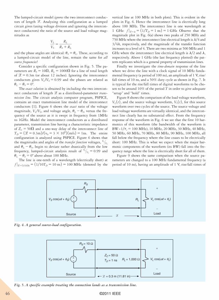
46 ©2011 IEEE
The lumped-circuit model ignores the two interconnect conduc-tors of length l. Analyzing this configuration as a lumped circuit gives (using voltage division and ignoring the intercon-nect conductors) the ratio of the source and load voltage mag-nitudes as
VL
VS
5RL
RS 1 RL
and the phase angles are identical: uS 5 uL. These, according to a lumped-circuit model of the line, remain the same for all source frequencies!
Consider a specific configuration shown in Fig. 5. The pa-rameters are RS 5 10V, RL 5 1000V for a line of total length of l5 0.3m (or about 12 inches). Ignoring the interconnect conductors gives VL/VS 5 0.99 and the phases are related as uL 2 uS 5 0o.
The exact solution is obtained by including the two intercon-nect conductors of length l as a distributed-parameter trans-mission line. The circuit analysis computer program, PSPICE, contains an exact transmission line model of the interconnect conductors [1]. Figure 6 shows the exact ratio of the voltage magnitude, VL/VS, and voltage angle, uL 2 uS, versus the fre-quency of the source as it is swept in frequency from 1MHz to 1GHz. Model the interconnect conductors as a distributed parameter, transmission line having a characteristic impedance of ZC 5 50V and a one-way delay of the interconnect line of TD 5 1l5 0.3m 2 / 1v0 5 3 3 108 2 1m/s 2 5 1ns. The entire configuration is analyzed using PSPICE. Figure 6 shows that the magnitudes and angles of the transfer function voltages, VL@VS
and uL 2 uS, begin to deviate rather drastically from the low frequency, lumped-circuit analysis result of VL@VS
5 0.99 and uL 2 uS 5 0o above about 100 MHz.
The line is one-tenth of a wavelength (electrically short) at f 0l5 11/102l 5 11/10TD 5 10 ns 2 5 100 MHz (denoted by the
vertical line at 100 MHz in both plots). This is evident in the plots in Fig. 6. Hence the interconnect line is electrically long above 100 MHz. The interconnect line is one wavelength at 1 GHz: f 0l5l 5 11/TD 5 1 ns 2 5 1 GHz Observe that the magnitude plot in Fig. 6(a) shows two peaks of 250 MHz and 750 MHz where the interconnect line electrical length is l/4 and 3/4l, respectively, and the magnitude of the transfer function increases to a level of 4. There are two minima at 500 MHz and 1 GHz where the interconnect line electrical length is l/2 and l, respectively. Above 1 GHz (the last frequency plotted) the pat-tern replicates which is a general property of transmission lines.
Finally we investigate the time-domain response of the line where we drive the line with a clock signal of 10 MHz funda-mental frequency (a period of 100 ns), an amplitude of 1 V, rise/fall times of 10 ns, and a 50% duty cycle as shown in Fig. 7. It is typical for the rise/fall times of digital waveforms to be cho-sen to be around 10% of the period T in order to give adequate “setup” and “hold” times.
Figure 8 shows the comparison of the load voltage waveform, VL 1 t 2 , and the source voltage waveform, VS 1 t 2 , for this source waveform over two cycles of the source. The source voltage and load voltage waveforms are virtually identical, and the intercon-nect line clearly has no substantial effect. From the frequency response of the waveform in Fig. 6 we see that the first 10 har-monics of this waveform (the bandwidth of the waveform is BW=1/tr 5 100 MHz), 10 MHz, 20 MHz, 30 MHz, 40 MHz, 50 MHz, 60 MHz, 70 MHz, 80 MHz, 90 MHz, 100 MHz, all fall below the frequency where the line ceases to be electrically short: 100 MHz. This is what we expect when the major har-monic components of the waveform (its BW) fall into the fre-quency range where the line is electrically short for all of them.
Figure 9 shows the same comparison when the source pa-rameters are changed to a 100 MHz fundamental frequency (a period of 10 ns), having an amplitude of 1 V, rise/fall times of
Source Load
RS
RLVS cos(ωt + θS) VL cos(ωt + θL)+−
−
+
l
Fig. 4. A general source-load configuration.
Source Load
RS = 10 Ω
RL = 1,000 ΩZC = 50 Ω
VS cos(ωt + θS) VL cos(ωt + θL)+−
−
+
TD = 1 ns
l = 0.3 m (11.81 in)
Fig. 5. A specific example treating the connection lands as a transmission line.
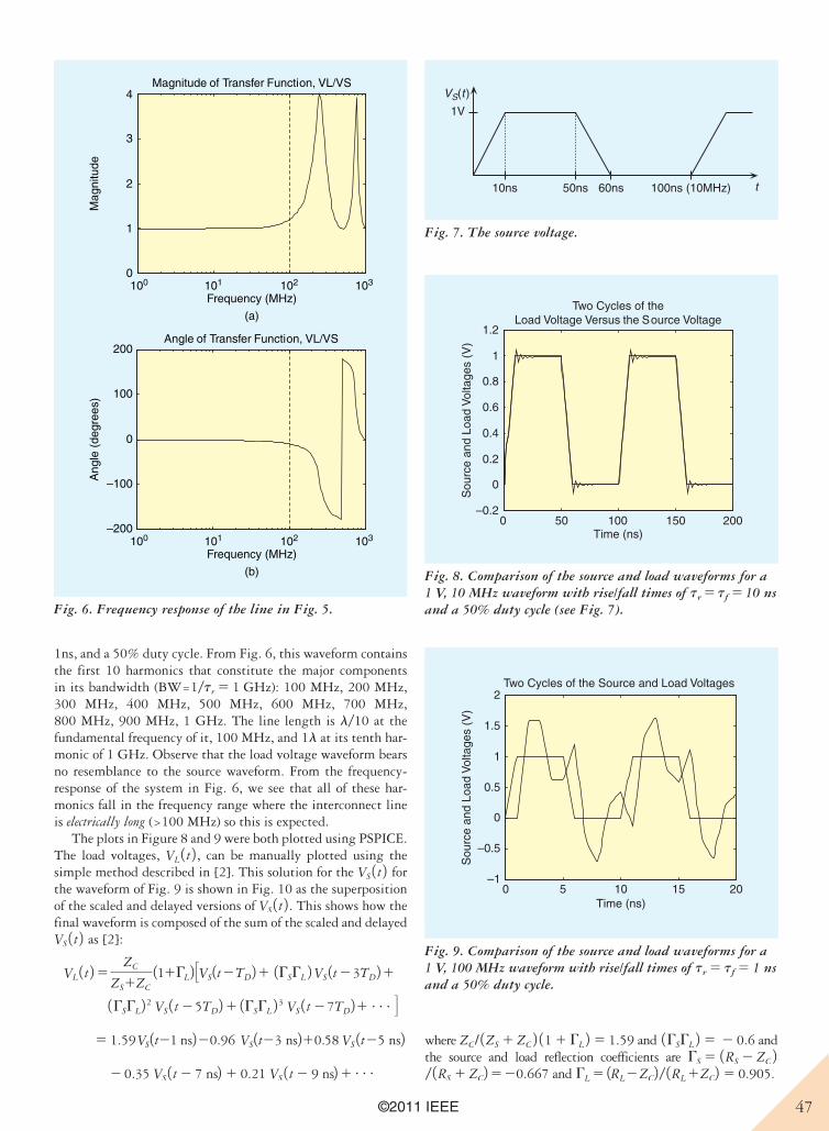
47©2011 IEEE
1ns, and a 50% duty cycle. From Fig. 6, this waveform contains the first 10 harmonics that constitute the major components in its bandwidth (BW=1/tr 5 1 GHz): 100 MHz, 200 MHz, 300 MHz, 400 MHz, 500 MHz, 600 MHz, 700 MHz, 800 MHz, 900 MHz, 1 GHz. The line length is l/10 at the fundamental frequency of it, 100 MHz, and 1l at its tenth har-monic of 1 GHz. Observe that the load voltage waveform bears no resemblance to the source waveform. From the frequency-response of the system in Fig. 6, we see that all of these har-monics fall in the frequency range where the interconnect line is electrically long (>100 MHz) so this is expected.
The plots in Figure 8 and 9 were both plotted using PSPICE. The load voltages, VL 1 t 2 , can be manually plotted using the simple method described in [2]. This solution for the VS 1 t 2 for the waveform of Fig. 9 is shown in Fig. 10 as the superposition of the scaled and delayed versions of VS 1 t 2 . This shows how the final waveform is composed of the sum of the scaled and delayed VS 1 t 2 as [2]:
VL 1 t 25 ZC
ZS1ZC
111GL2 SVS1t2TD21 1GSGL 2 VS 1t 23TD211GSGL2 2 VS 1 t 25TD21 1GSGL 2 3 VS 1 t 27TD21cT
5 1.59 VS1t21 ns220.96 VS1t23 ns210.58 VS 1t25 ns22 0.35 VS 1 t 2 7 ns2 1 0.21 VS 1 t 2 9 ns21c
where ZC/ 1ZS 1 ZC 2 11 1 GL 2 5 1.59 and 1GSGL 2 5 2 0.6 and the source and load reflection coefficients are GS 5 1RS 2 ZC 2/ 1RS 1 ZC2520.667 and GL 5 1RL2ZC2 / 1RL 1ZC2 5 0.905.
100 101 102 1030
1
2
3
4
Frequency (MHz)
100 101 102 103
Frequency (MHz)
(a)
(b)
Mag
nitu
deMagnitude of Transfer Function, VL/VS
–200
–100
0
100
200
Ang
le (
degr
ees)
Angle of Transfer Function, VL/VS
Fig. 6. Frequency response of the line in Fig. 5.
0 50 100 150 200–0.2
0
0.2
0.4
0.6
0.8
1
1.2
Time (ns)
Sou
rce
and
Load
Vol
tage
s (V
)
Two Cycles of theLoad Voltage Versus the Source Voltage
Fig. 8. Comparison of the source and load waveforms for a 1 V, 10 MHz waveform with rise/fall times of tr 5 tf 5 10 ns and a 50% duty cycle (see Fig. 7).
Fig. 7. The source voltage.
t
1V
VS(t )
10ns 100ns (10MHz)50ns 60ns
Fig. 9. Comparison of the source and load waveforms for a 1 V, 100 MHz waveform with rise/fall times of tr 5 tf 5 1 ns and a 50% duty cycle.
0 5 10 15 20–1
–0.5
0
0.5
1
1.5
2
Time (ns)
Sou
rce
and
Load
Vol
tage
s (V
)
Two Cycles of the Source and Load Voltages
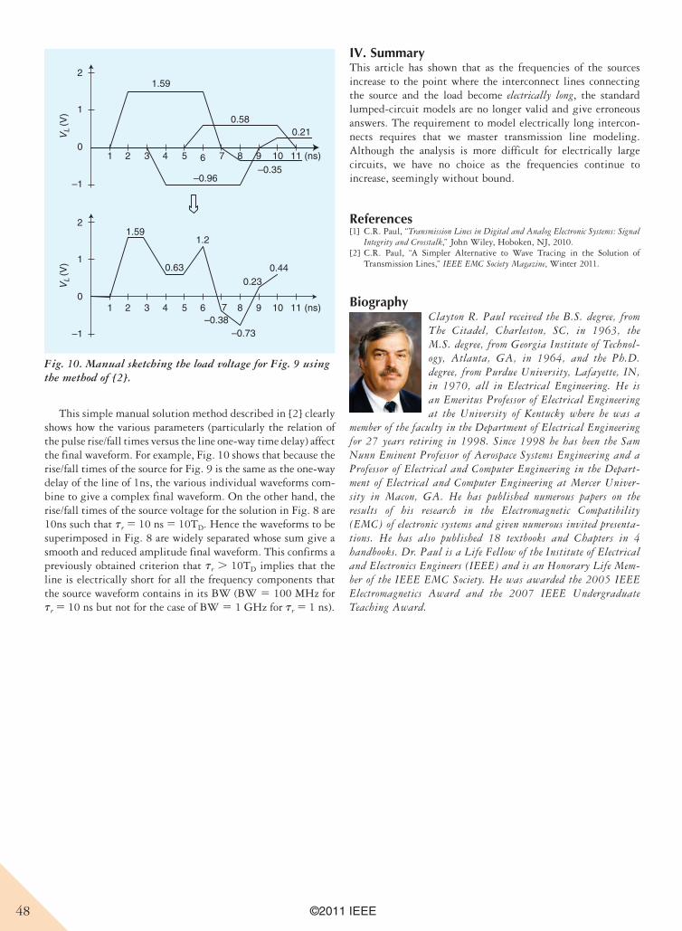
48 ©2011 IEEE
This simple manual solution method described in [2] clearly shows how the various parameters (particularly the relation of the pulse rise/fall times versus the line one-way time delay) affect the final waveform. For example, Fig. 10 shows that because the rise/fall times of the source for Fig. 9 is the same as the one-way delay of the line of 1ns, the various individual waveforms com-bine to give a complex final waveform. On the other hand, the rise/fall times of the source voltage for the solution in Fig. 8 are 10ns such that tr 5 10 ns 5 10TD. Hence the waveforms to be superimposed in Fig. 8 are widely separated whose sum give a smooth and reduced amplitude final waveform. This confirms a previously obtained criterion that tr . 10TD implies that the line is electrically short for all the frequency components that the source waveform contains in its BW (BW 5 100 MHz for tr 5 10 ns but not for the case of BW 5 1 GHz for tr 5 1 ns).
IV. SummaryThis article has shown that as the frequencies of the sources increase to the point where the interconnect lines connecting the source and the load become electrically long, the standard lumped-circuit models are no longer valid and give erroneous answers. The requirement to model electrically long intercon-nects requires that we master transmission line modeling. Although the analysis is more difficult for electrically large circuits, we have no choice as the frequencies continue to increase, seemingly without bound.
References[1] C.R. Paul, “Transmission Lines in Digital and Analog Electronic Systems: Signal
Integrity and Crosstalk,” John Wiley, Hoboken, NJ, 2010.[2] C.R. Paul, “A Simpler Alternative to Wave Tracing in the Solution of
Transmission Lines,” IEEE EMC Society Magazine, Winter 2011.
BiographyClayton R. Paul received the B.S. degree, from The Citadel, Charleston, SC, in 1963, the M.S. degree, from Georgia Institute of Technol-ogy, Atlanta, GA, in 1964, and the Ph.D. degree, from Purdue University, Lafayette, IN, in 1970, all in Electrical Engineering. He is an Emeritus Professor of Electrical Engineering at the University of Kentucky where he was a
member of the faculty in the Department of Electrical Engineering for 27 years retiring in 1998. Since 1998 he has been the Sam Nunn Eminent Professor of Aerospace Systems Engineering and a Professor of Electrical and Computer Engineering in the Depart-ment of Electrical and Computer Engineering at Mercer Univer-sity in Macon, GA. He has published numerous papers on the results of his research in the Electromagnetic Compatibility (EMC) of electronic systems and given numerous invited presenta-tions. He has also published 18 textbooks and Chapters in 4 handbooks. Dr. Paul is a Life Fellow of the Institute of Electrical and Electronics Engineers (IEEE) and is an Honorary Life Mem-ber of the IEEE EMC Society. He was awarded the 2005 IEEE Electromagnetics Award and the 2007 IEEE Undergraduate Teaching Award.
1 2 3 4 5 6 7 8 9 10 11 (ns)
1 2 3 4 5 6 7 8 9 10 11 (ns)
VL
(V)
2
–1
0
1
VL
(V)
2
–1
0
1
1.59
1.59
0.580.21
–0.35–0.96
1.2
0.230.44
–0.38–0.73
0.63
Fig. 10. Manual sketching the load voltage for Fig. 9 using the method of [2].
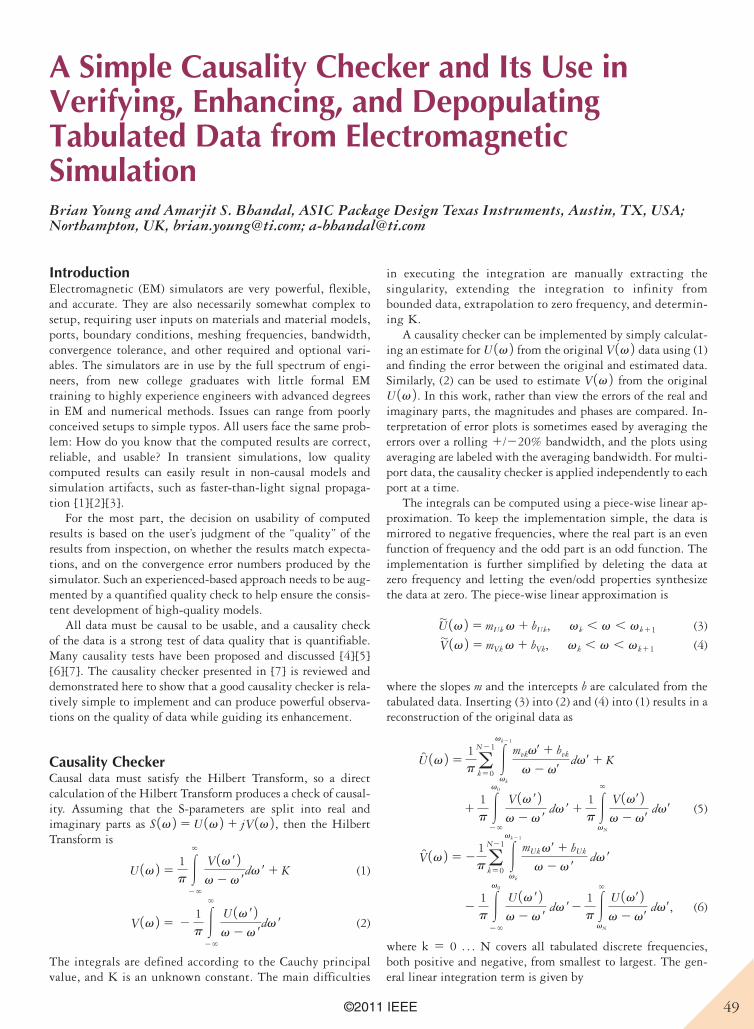
49©2011 IEEE
A Simple Causality Checker and Its Use in Verifying, Enhancing, and Depopulating Tabulated Data from Electromagnetic SimulationBrian Young and Amarjit S. Bhandal, ASIC Package Design Texas Instruments, Austin, TX, USA; Northampton, UK, [email protected]; [email protected]
IntroductionElectromagnetic (EM) simulators are very powerful, flexible, and accurate. They are also necessarily somewhat complex to setup, requiring user inputs on materials and material models, ports, boundary conditions, meshing frequencies, bandwidth, convergence tolerance, and other required and optional vari-ables. The simulators are in use by the full spectrum of engi-neers, from new college graduates with little formal EM training to highly experience engineers with advanced degrees in EM and numerical methods. Issues can range from poorly conceived setups to simple typos. All users face the same prob-lem: How do you know that the computed results are correct, reliable, and usable? In transient simulations, low quality computed results can easily result in non-causal models and simulation artifacts, such as faster-than-light signal propaga-tion [1][2][3].
For the most part, the decision on usability of computed results is based on the user’s judgment of the “quality” of the results from inspection, on whether the results match expecta-tions, and on the convergence error numbers produced by the simulator. Such an experienced-based approach needs to be aug-mented by a quantified quality check to help ensure the consis-tent development of high-quality models.
All data must be causal to be usable, and a causality check of the data is a strong test of data quality that is quantifiable. Many causality tests have been proposed and discussed [4][5][6][7]. The causality checker presented in [7] is reviewed and demonstrated here to show that a good causality checker is rela-tively simple to implement and can produce powerful observa-tions on the quality of data while guiding its enhancement.
Causality CheckerCausal data must satisfy the Hilbert Transform, so a direct calculation of the Hilbert Transform produces a check of causal-ity. Assuming that the S-parameters are split into real and imaginary parts as S 1v 2 5 U 1v 2 1 jV 1v 2 , then the Hilbert Transform is
U 1v 2 51p 3
`
2`
V 1v r 2v 2 v r
dv r1 K (1)
V 1v 2 5 21p 3
`
2`
U 1v r 2v 2 v r
dv r (2)
The integrals are defined according to the Cauchy principal value, and K is an unknown constant. The main difficulties
in executing the integration are manually extracting the singularity, extending the integration to infinity from bounded data, extrapolation to zero frequency, and determin-ing K.
A causality checker can be implemented by simply calculat-ing an estimate for U 1v 2 from the original V 1v 2 data using (1) and finding the error between the original and estimated data. Similarly, (2) can be used to estimate V 1v 2 from the original U 1v 2 . In this work, rather than view the errors of the real and imaginary parts, the magnitudes and phases are compared. In-terpretation of error plots is sometimes eased by averaging the errors over a rolling 1/220% bandwidth, and the plots using averaging are labeled with the averaging bandwidth. For multi-port data, the causality checker is applied independently to each port at a time.
The integrals can be computed using a piece-wise linear ap-proximation. To keep the implementation simple, the data is mirrored to negative frequencies, where the real part is an even function of frequency and the odd part is an odd function. The implementation is further simplified by deleting the data at zero frequency and letting the even/odd properties synthesize the data at zero. The piece-wise linear approximation is
U| 1v 2 5 mUk v 1 bUk, vk , v , vk11 (3)
V| 1v 2 5 mVk v 1 bVk, vk , v , vk11 (4)
where the slopes m and the intercepts b are calculated from the tabulated data. Inserting (3) into (2) and (4) into (1) results in a reconstruction of the original data as
U 1v 2 51pa
N21
k503
vk21
vk
mvkvr1 bvk
v 2 vrdvr1 K
11p 3
v0
2`
V 1v r 2v 2 v r
dv r11p 3
`
vN
V 1vr 2v 2 vr
dvr (5)
V 1v 2 5 21pa
N21
k503
vk21
vk
mUkvr1 bUk
v 2 v r dv r
21p 3
v0
2`
U 1v r 2v 2 v r
dv r21p 3
`
vN
U 1vr 2v 2 vr
dvr, (6)
where k 5 0 . . . N covers all tabulated discrete frequencies, both positive and negative, from smallest to largest. The gen-eral linear integration term is given by
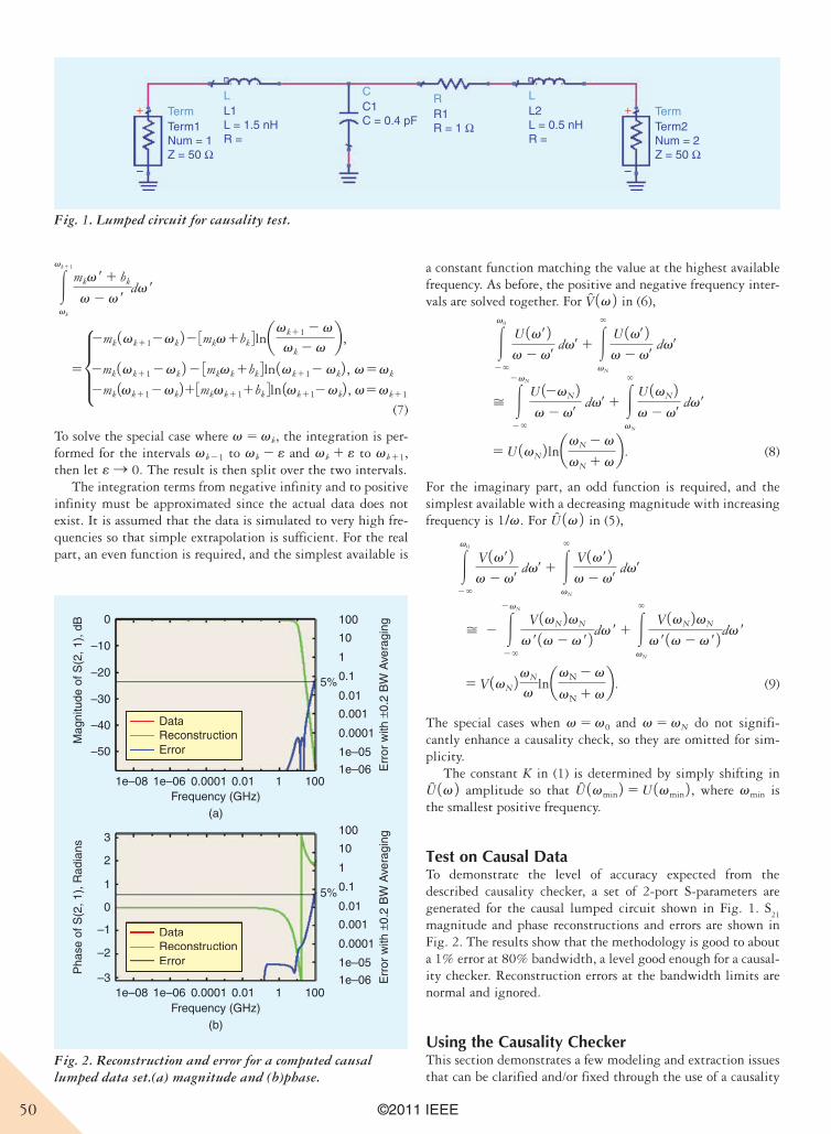
50 ©2011 IEEE
3
vk11
vk
mkv r1 bk
v 2 v rdv r
5µ2mk 1vk112vk 22 3mkv1bk 4lnavk11 2 v
vk 2 vb ,
2mk 1vk112vk 22 3mkvk1bk 4ln 1vk112 vk2 , v5vk
2mk 1vk112vk213mkvk111bk 4ln 1vk112vk2 , v5vk11
(7)
To solve the special case where v 5 vk, the integration is per-formed for the intervals vk21 to vk 2 e and vk 1 e to vk11, then let e S 0. The result is then split over the two intervals.
The integration terms from negative infinity and to positive infinity must be approximated since the actual data does not exist. It is assumed that the data is simulated to very high fre-quencies so that simple extrapolation is sufficient. For the real part, an even function is required, and the simplest available is
a constant function matching the value at the highest available frequency. As before, the positive and negative frequency inter-vals are solved together. For V 1v 2 in (6),
3
v0
2`
U 1vr 2v 2 vr
dvr1 3
`
vN
U 1vr 2v 2 vr
dvr
> 3
2vN
2`
U 12vN 2v 2 vr
dvr1 3
`
vN
U 1vN 2v 2 vr
dvr
5 U 1vN 2 lnavN 2 v
vN 1 vb . (8)
For the imaginary part, an odd function is required, and the simplest available with a decreasing magnitude with increasing frequency is 1/v. For U 1v 2 in (5),
3
v0
2`
V 1vr 2v 2 vr
dvr1 3
`
vN
V 1vr 2v 2 vr
dvr
> 2 3
2vN
2`
V 1v N 2v N
v r 1v 2 v r 2 dv r1 3
`
vN
V 1vN 2v N
v r 1v 2 v r 2 dv r
5 V 1vN 2vN
vlnavN 2 v
vN 1 vb . (9)
The special cases when v 5 v0 and v 5 vN do not signifi-cantly enhance a causality check, so they are omitted for sim-plicity.
The constant K in (1) is determined by simply shifting in U 1v 2 amplitude so that U 1vmin 2 5 U 1vmin 2 , where vmin is the smallest positive frequency.
Test on Causal DataTo demonstrate the level of accuracy expected from the described causality checker, a set of 2-port S-parameters are generated for the causal lumped circuit shown in Fig. 1. S
21
magnitude and phase reconstructions and errors are shown in Fig. 2. The results show that the methodology is good to about a 1% error at 80% bandwidth, a level good enough for a causal-ity checker. Reconstruction errors at the bandwidth limits are normal and ignored.
Using the Causality CheckerThis section demonstrates a few modeling and extraction issues that can be clarified and/or fixed through the use of a causality
+
–
+
–
TermTerm1Num = 1Z = 50 Ω
TermTerm2Num = 2Z = 50 Ω
LL1L = 1.5 nHR =
LL2L = 0.5 nHR =
CC1C = 0.4 pF
RR1R = 1 Ω
Fig. 1. Lumped circuit for causality test.
0
–10
–20
–30
–40
–50
1e–08 1e–06 0.0001Frequency (GHz)
Mag
nitu
de o
f S(2
, 1),
dB
0.01 1 100
1e–08 1e–06 0.0001Frequency (GHz)
(a)
(b)
0.01 1 100
100
10
1
0.1
0.01
0.001
0.0001
1e–05
1e–06
5%
Err
or w
ith ±
0.2
BW
Ave
ragi
ng
3
2
1
0
–1
–2
–3
Pha
se o
f S(2
, 1),
Rad
ians
100
10
1
0.1
0.01
0.001
0.0001
1e–05
1e–06
5%
Err
or w
ith ±
0.2
BW
Ave
ragi
ng
DataReconstructionError
DataReconstructionError
DataReconstructionError
DataReconstructionError
Fig. 2. Reconstruction and error for a computed causal lumped data set.(a) magnitude and (b)phase.
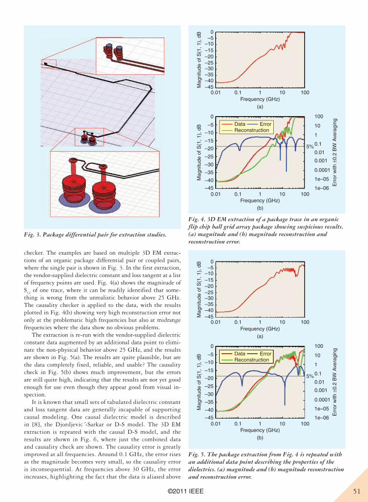
51©2011 IEEE
checker. The examples are based on multiple 3D EM extrac-tions of an organic package differential pair or coupled pairs, where the single pair is shown in Fig. 3. In the first extraction, the vendor-supplied dielectric constant and loss tangent at a list of frequency points are used. Fig. 4(a) shows the magnitude of S
11 of one trace, where it can be readily identified that some-
thing is wrong from the unrealistic behavior above 25 GHz. The causality checker is applied to the data, with the results plotted in Fig. 4(b) showing very high reconstruction error not only at the problematic high frequencies but also at midrange frequencies where the data show no obvious problems.
The extraction is re-run with the vendor-supplied dielectric constant data augmented by an additional data point to elimi-nate the non-physical behavior above 25 GHz, and the results are shown in Fig. 5(a). The results are quite plausible, but are the data completely fixed, reliable, and usable? The causality check in Fig. 5(b) shows much improvement, but the errors are still quite high, indicating that the results are not yet good enough for use even though they appear good from visual in-spection.
It is known that small sets of tabulated dielectric constant and loss tangent data are generally incapable of supporting causal modeling. One causal dielectric model is described in [8], the Djordjevic´-Sarkar or D-S model. The 3D EM extraction is repeated with the causal D-S model, and the results are shown in Fig. 6, where just the combined data and causality check are shown. The causality error is greatly improved at all frequencies. Around 0.1 GHz, the error rises as the magnitude becomes very small, so the causality error is inconsequential. At frequencies above 30 GHz, the error increases, highlighting the fact that the data is aliased above
0
–10–5
–35–30–25–20–15
–40–45
0
–10
–5
–35
–30
–25
–20
–15
–40
–45
0.01 0.1 1Frequency (GHz)
Mag
nitu
de o
f S(1
, 1),
dB
Mag
nitu
de o
f S(1
, 1),
dB
10 100
0.01 0.1 1 10 100Frequency (GHz)
(a)
(b)
100
10
1
0.1
0.01
0.001
0.0001
1e–05
1e–06
5%
Err
or w
ith ±
0.2
BW
Ave
ragi
ngDataReconstruction
ErrorDataReconstruction
Error
Fig. 5. The package extraction from Fig. 4 is repeated with an additional data point describing the properties of the dielectrics. (a) magnitude and (b) magnitude reconstruction and reconstruction error.
Fig. 3. Package differential pair for extraction studies.
Fig. 4. 3D EM extraction of a package trace in an organic flip chip ball grid array package showing suspicious results. (a) magnitude and (b) magnitude reconstruction and reconstruction error.
0
–10–5
–35–30–25–20–15
–40–45
0
–10
–5
–35
–30
–25
–20
–15
–40
–45
0.01 0.1 1Frequency (GHz)
Mag
nitu
de o
f S(1
, 1),
dB
Mag
nitu
de o
f S(1
, 1),
dB
10 100
0.01 0.1 1 10 100Frequency (GHz)
(a)
(b)
100
10
1
0.1
0.01
0.001
0.0001
1e–05
1e–06
5%
Err
or w
ith ±
0.2
BW
Ave
ragi
ngDataReconstruction
Error
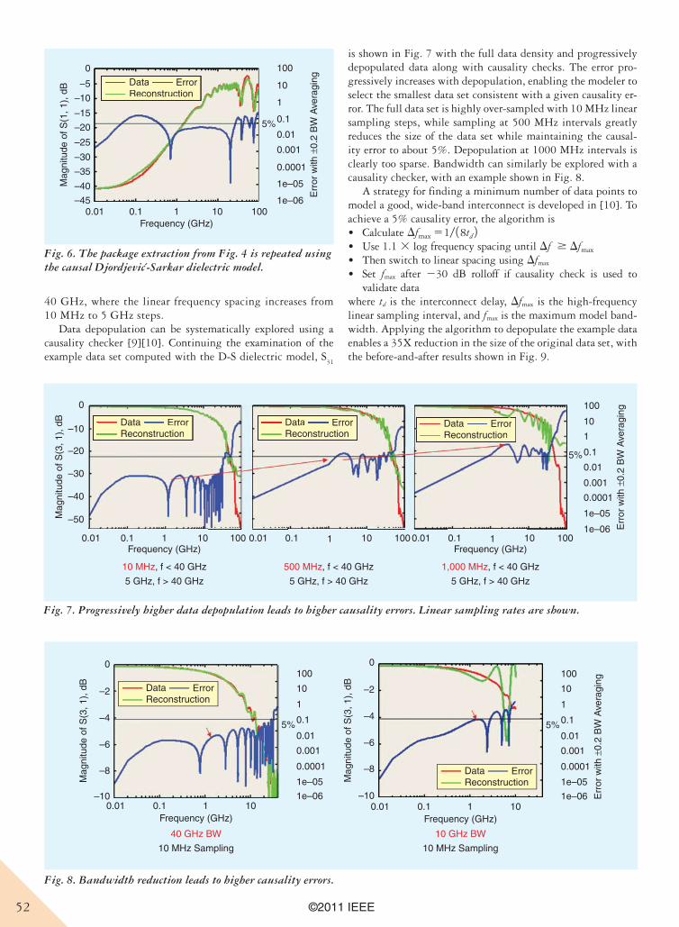
52 ©2011 IEEE
40 GHz, where the linear frequency spacing increases from 10 MHz to 5 GHz steps.
Data depopulation can be systematically explored using a causality checker [9][10]. Continuing the examination of the example data set computed with the D-S dielectric model, S
31
is shown in Fig. 7 with the full data density and progressively depopulated data along with causality checks. The error pro-gressively increases with depopulation, enabling the modeler to select the smallest data set consistent with a given causality er-ror. The full data set is highly over-sampled with 10 MHz linear sampling steps, while sampling at 500 MHz intervals greatly reduces the size of the data set while maintaining the causal-ity error to about 5%. Depopulation at 1000 MHz intervals is clearly too sparse. Bandwidth can similarly be explored with a causality checker, with an example shown in Fig. 8.
A strategy for finding a minimum number of data points to model a good, wide-band interconnect is developed in [10]. To achieve a 5% causality error, the algorithm is• Calculate Dfmax 51/ 18td 2• Use 1.1 3 log frequency spacing until Df $ Dfmax
• Then switch to linear spacing using Dfmax
• Set fmax after 230 dB rolloff if causality check is used to validate data
where td is the interconnect delay, Dfmax is the high-frequency linear sampling interval, and fmax is the maximum model band-width. Applying the algorithm to depopulate the example data enables a 35X reduction in the size of the original data set, with the before-and-after results shown in Fig. 9.
0
–10
–5
–35
–30
–25
–20
–15
–40
–45
Mag
nitu
de o
f S(1
, 1),
dB
0.01 0.1 1 10 100Frequency (GHz)
100
10
1
0.1
0.01
0.001
0.0001
1e–05
1e–06
5%
Err
or w
ith ±
0.2
BW
Ave
ragi
ngDataReconstruction
ErrorDataReconstruction
Error
Fig. 6. The package extraction from Fig. 4 is repeated using the causal Djordjevic-Sarkar dielectric model.
0
–10
–30
–20
–40
–50Mag
nitu
de o
f S(3
, 1),
dB
0.01 0.1 1 10 100Frequency (GHz)
10 MHz, f < 40 GHz
5 GHz, f > 40 GHz
500 MHz, f < 40 GHz
5 GHz, f > 40 GHz
1,000 MHz, f < 40 GHz
5 GHz, f > 40 GHz
0.01 0.1 1 10 100 0.01 0.1 1 10 100Frequency (GHz)
100
10
1
0.1
0.01
0.001
0.0001
1e–05
1e–06
5%
Err
or w
ith ±
0.2
BW
Ave
ragi
ng
DataReconstruction
Error DataReconstruction
Error DataReconstruction
ErrorDataReconstruction
Error DataReconstruction
Error DataReconstruction
Error
Fig. 7. Progressively higher data depopulation leads to higher causality errors. Linear sampling rates are shown.
Fig. 8. Bandwidth reduction leads to higher causality errors.
0
–2
–4
–6
–8
–10
Frequency (GHz)
Mag
nitu
de o
f S(3
, 1),
dB
0.01 0.1 1 10
100
10
1
0.1
0.01
0.001
0.0001
1e–05
1e–06
5%
DataReconstruction
Error
40 GHz BW
10 MHz Sampling
0
–2
–4
–6
–8
–10
Mag
nitu
de o
f S(3
, 1),
dB
Frequency (GHz)0.01 0.1 1 10
100
10
1
0.1
0.01
0.001
0.0001
1e–05
1e–06
5%
Err
or w
ith ±
0.2
BW
Ave
ragi
ng
DataReconstruction
Error
10 GHz BW
10 MHz Sampling
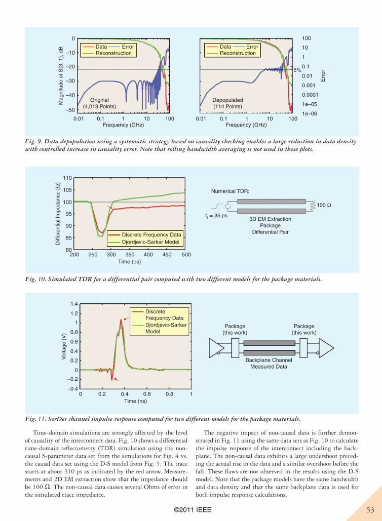
53©2011 IEEE
Time-domain simulations are strongly affected by the level of causality of the interconnect data. Fig. 10 shows a differential time-domain reflectometry (TDR) simulation using the non-causal S-parameter data set from the simulations for Fig. 4 vs. the causal data set using the D-S model from Fig. 5. The trace starts at about 310 ps as indicated by the red arrow. Measure-ments and 2D EM extraction show that the impedance should be 100 V. The non-causal data causes several Ohms of error in the simulated trace impedance.
The negative impact of non-causal data is further demon-strated in Fig. 11 using the same data sets as Fig. 10 to calculate the impulse response of the interconnect including the back-plane. The non-causal data exhibits a large undershoot preced-ing the actual rise in the data and a similar overshoot before the fall. These flaws are not observed in the results using the D-S model. Note that the package models have the same bandwidth and data density and that the same backplane data is used for both impulse response calculations.
0
–10
–30
–20
–40
–50
Mag
nitu
de o
f S(3
, 1),
dB
0.01 0.1 1 10 100Frequency (GHz)
0.01 0.1 1 10 100Frequency (GHz)
100
10
1
0.1
0.01
0.001
0.0001
1e–05
1e–06
5%
Err
or
DataReconstruction
Error DataReconstruction
ErrorDataReconstruction
Error DataReconstruction
Error
Original(4,013 Points)
Depopulated(114 Points)
Fig. 9. Data depopulation using a systematic strategy based on causality checking enables a large reduction in data density with controlled increase in causality error. Note that rolling bandwidth averaging is not used in these plots.
110
105
100
95
90
85
80200 250 300 350
Time (ps)
Diff
eren
tial I
mpe
danc
e (Ω
)
400 450 500
Numerical TDR:
3D EM ExtractionPackage
Differential Pair
tr = 35 ps
100 Ω
Discrete Frequency DataDjordjevic-Sarkar ModelDiscrete Frequency DataDjordjevic-Sarkar Model
35
Fig. 10. Simulated TDR for a differential pair computed with two different models for the package materials.
1.4
1.2
1
0.8
0.6
0.4
0.2
0
–0.2
–0.40 0.2 0.4
Time (ns)
Vol
tage
(V
)
0.6 0.8 1
DiscreteFrequency DataDjordjevic-SarkarModel
Package(this work)
Backplane ChannelMeasured Data
Package(this work)
Fig. 11. SerDes channel impulse response computed for two different models for the package materials.
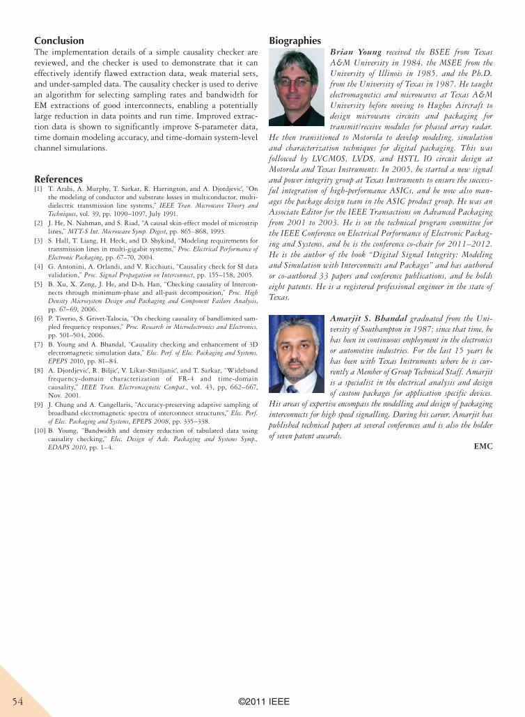
54 ©2011 IEEE
ConclusionThe implementation details of a simple causality checker are reviewed, and the checker is used to demonstrate that it can effectively identify flawed extraction data, weak material sets, and under-sampled data. The causality checker is used to derive an algorithm for selecting sampling rates and bandwidth for EM extractions of good interconnects, enabling a potentially large reduction in data points and run time. Improved extrac-tion data is shown to significantly improve S-parameter data, time domain modeling accuracy, and time-domain system-level channel simulations.
References[1] T. A rabi, A. Murphy, T. Sarkar, R. Harrington, and A. Djordjevic, “On
the modeling of conductor and substrate losses in multiconductor, multi-dielectric transmission line systems,” IEEE Tran. Microwave Theory and Techniques, vol. 39, pp. 1090–1097, July 1991.
[2] J. He, N . Nahman, and S. Riad, “A causal skin-effect model of microstrip lines,” MTT-S Int. Microwave Symp. Digest, pp. 865–868, 1993.
[3] S. Hall, T. Liang, H. Heck, and D. Shykind, “Modeling requirements for transmission lines in multi-gigabit systems,” Proc. Electrical Performance of Electronic Packaging, pp. 67–70, 2004.
[4] G. Anton ini, A. Orlandi, and V. Ricchiuti, “Causality check for SI data validation,” Proc. Signal Propagation on Interconnect, pp. 155–158, 2005.
[5] B. Xu, X . Zeng, J. He, and D-h. Han, “Checking causality of Intercon-nects through minimum-phase and all-pass decomposition,” Proc. High Density Microsystem Design and Packaging and Component Failure Analysis, pp. 67–69, 2006.
[6] P. Tiver io, S. Grivet-Talocia, “On checking causality of bandlimited sam-pled frequency responses,” Proc. Research in Microelectronics and Electronics, pp. 501–504, 2006.
[7] B. Young and A. Bhandal, “Causality checking and enhancement of 3D electromagnetic simulation data,” Elec. Perf. of Elec. Packaging and Systems, EPEPS 2010, pp. 81–84.
[8] A. Djordjevic, R. Biljic, V. Likar-Smiljanic, and T. Sarkar, “Wideband frequency-domain characterization of FR-4 and time-domain causality,” IEEE Tran. Electromagnetic Compat., vol. 43, pp, 662–667, Nov. 2001.
[9] J. Chung and A. Cangellaris, “Accuracy-preserving adaptive sampling of broadband electromagnetic spectra of interconnect structures,” Elec. Perf. of Elec. Packaging and Systems, EPEPS 2008, pp. 335–338.
[10] B. Young, “Bandwidth and density reduction of tabulated data using causality checking,” Elec. Design of Adv. Packaging and Systems Symp., EDAPS 2010, pp. 1–4.
BiographiesBrian Young received the BSEE from Texas A&M University in 1984, the MSEE from the University of Illinois in 1985, and the Ph.D. from the University of Texas in 1987. He taught electromagnetics and microwaves at Texas A&M University before moving to Hughes Aircraft to design microwave circuits and packaging for transmit/receive modules for phased array radar.
He then transitioned to Motorola to develop modeling, simulation and characterization techniques for digital packaging. This was followed by LVCMOS, LVDS, and HSTL IO circuit design at Motorola and Texas Instruments. In 2005, he started a new signal and power integrity group at Texas Instruments to ensure the success-ful integration of high-performance ASICs, and he now also man-ages the package design team in the ASIC product group. He was an Associate Editor for the IEEE Transactions on Advanced Packaging from 2001 to 2003. He is on the technical program committee for the IEEE Conference on Electrical Performance of Electronic Packag-ing and Systems, and he is the conference co-chair for 2011–2012. He is the author of the book “Digital Signal Integrity: Modeling and Simulation with Interconnects and Packages” and has authored or co-authored 33 papers and conference publications, and he holds eight patents. He is a registered professional engineer in the state of Texas.
Amarjit S. Bhandal graduated from the Uni-versity of Southampton in 1987; since that time, he has been in continuous employment in the electronics or automotive industries. For the last 15 years he has been with Texas Instruments where he is cur-rently a Member of Group Technical Staff. Amarjit is a specialist in the electrical analysis and design of custom packages for application specific devices.
His areas of expertise encompass the modelling and design of packaging interconnects for high speed signalling. During his career, Amarjit has published technical papers at several conferences and is also the holder of seven patent awards. EMC
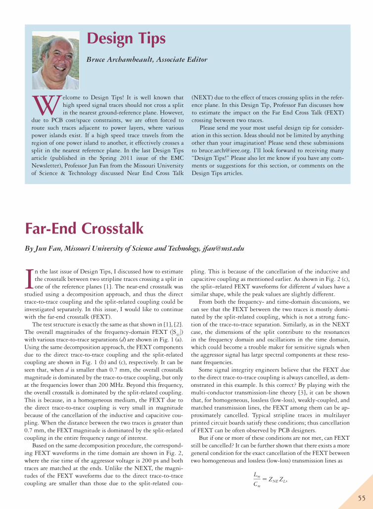
55
Far-End CrosstalkBy Jun Fan, Missouri University of Science and Technology, [email protected]
Welcome to Design Tips! It is well known that high speed signal traces should not cross a split in the nearest ground-reference plane. However,
due to PCB cost/space constraints, we are often forced to route such traces adjacent to power layers, where various power islands exist. If a high speed trace travels from the region of one power island to another, it effectively crosses a split in the nearest reference plane. In the last Design Tips article (published in the Spring 2011 issue of the EMC Newsletter), Professor Jun Fan from the Missouri University of Science & Technology discussed Near End Cross Talk
(NEXT) due to the effect of traces crossing splits in the refer-ence plane. In this Design Tip, Professor Fan discusses how to estimate the impact on the Far End Cross Talk (FEXT) crossing between two traces.
Please send me your most useful design tip for consider-ation in this section. Ideas should not be limited by anything other than your imagination! Please send these submissions to [email protected]. I’ll look forward to receiving many “Design Tips!” Please also let me know if you have any com-ments or suggestions for this section, or comments on the Design Tips articles.
Design TipsBruce Archambeault, Associate Editor
In the last issue of Design Tips, I discussed how to estimate the crosstalk between two stripline traces crossing a split in one of the reference planes [1]. The near-end crosstalk was
studied using a decomposition approach, and thus the direct trace-to-trace coupling and the split-related coupling could be investigated separately. In this issue, I would like to continue with the far-end crosstalk (FEXT).
The test structure is exactly the same as that shown in [1], [2]. The overall magnitudes of the frequency-domain FEXT (|S
41|)
with various trace-to-trace separations (d) are shown in Fig. 1 (a). Using the same decomposition approach, the FEXT components due to the direct trace-to-trace coupling and the split-related coupling are shown in Fig. 1 (b) and (c), respectively. It can be seen that, when d is smaller than 0.7 mm, the overall crosstalk magnitude is dominated by the trace-to-trace coupling, but only at the frequencies lower than 200 MHz. Beyond this frequency, the overall crosstalk is dominated by the split-related coupling. This is because, in a homogeneous medium, the FEXT due to the direct trace-to-trace coupling is very small in magnitude because of the cancellation of the inductive and capacitive cou-pling. When the distance between the two traces is greater than 0.7 mm, the FEXT
magnitude is dominated by the split-related
coupling in the entire frequency range of interest.Based on the same decomposition procedure, the correspond-
ing FEXT waveforms in the time domain are shown in Fig. 2, where the rise time of the aggressor voltage is 200 ps and both traces are matched at the ends. Unlike the NEXT, the magni-tudes of the FEXT waveforms due to the direct trace-to-trace coupling are smaller than those due to the split-related cou-
pling. This is because of the cancellation of the inductive and capacitive coupling as mentioned earlier. As shown in Fig. 2 (c), the split–related FEXT waveforms for different d values have a similar shape, while the peak values are slightly different.
From both the frequency- and time-domain discussions, we can see that the FEXT between the two traces is mostly domi-nated by the split-related coupling, which is not a strong func-tion of the trace-to-trace separation. Similarly, as in the NEXT case, the dimensions of the split contribute to the resonances in the frequency domain and oscillations in the time domain, which could become a trouble maker for sensitive signals when the aggressor signal has large spectral components at these reso-nant frequencies.
Some signal integrity engineers believe that the FEXT due to the direct trace-to-trace coupling is always cancelled, as dem-onstrated in this example. Is this correct? By playing with the multi-conductor transmission-line theory [3], it can be shown that, for homogeneous, lossless (low-loss), weakly-coupled, and matched transmission lines, the FEXT among them can be ap-proximately cancelled. Typical stripline traces in multilayer printed circuit boards satisfy these conditions; thus cancellation of FEXT can be often observed by PCB designers.
But if one or more of these conditions are not met, can FEXT still be cancelled? It can be further shown that there exists a more general condition for the exact cancellation of the FEXT between two homogeneous and lossless (low-loss) transmission lines as
Lm
Cm
5 ZNE ZL,
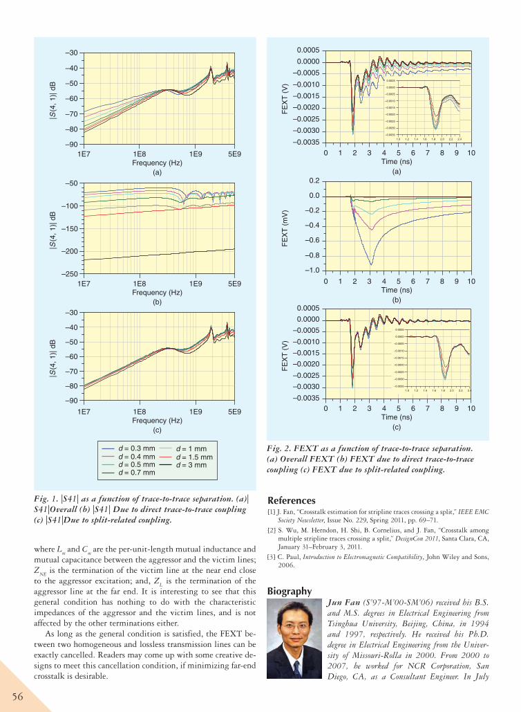
56
where Lm and C
m are the per-unit-length mutual inductance and
mutual capacitance between the aggressor and the victim lines; Z
NE is the termination of the victim line at the near end close
to the aggressor excitation; and, ZL is the termination of the
aggressor line at the far end. It is interesting to see that this general condition has nothing to do with the characteristic impedances of the aggressor and the victim lines, and is not affected by the other terminations either.
As long as the general condition is satisfied, the FEXT be-tween two homogeneous and lossless transmission lines can be exactly cancelled. Readers may come up with some creative de-signs to meet this cancellation condition, if minimizing far-end crosstalk is desirable.
References [1] J. Fan, “Crosstalk estimation for stripline traces crossing a split,” IEEE EMC
Society Newsletter, Issue No. 229, Spring 2011, pp. 69–71.
[2] S. Wu, M. Herndon, H. Shi, B. Cornelius, and J. Fan, “Crosstalk among multiple stripline traces crossing a split,” DesignCon 2011, Santa Clara, CA, January 31–February 3, 2011.
[3] C. Paul, Introduction to Electromagnetic Compatibility, John Wiley and Sons, 2006.
BiographyJun Fan (S’97-M’00-SM’06) received his B.S. and M.S. degrees in Electrical Engineering from Tsinghua University, Beijing, China, in 1994 and 1997, respectively. He received his Ph.D. degree in Electrical Engineering from the Univer-sity of Missouri-Rolla in 2000. From 2000 to 2007, he worked for NCR Corporation, San Diego, CA, as a Consultant Engineer. In July
1E8 1E91E7 5E9
–80
–70
–60
–50
–40
–90
–30
Frequency (Hz)
1E8 1E91E7 5E9Frequency (Hz)
1E8 1E91E7 5E9Frequency (Hz)
(a)
|S(4
, 1)|
dB
|S(4
, 1)|
dB
|S(4
, 1)|
dB
(b)
(c)
–200
–150
–100
–250
–50
–80
–70
–60
–50
–40
–90
–30
d = 0.3 mmd = 0.4 mmd = 0.5 mmd = 0.7 mm
d = 1 mmd = 1.5 mmd = 3 mm
Fig. 1. |S41| as a function of trace-to-trace separation. (a)| S41|Overall (b) |S41| Due to direct trace-to-trace coupling (c) |S41|Due to split-related coupling.
1 2 3 4 5 6 7 8 90 10
–0.0030
–0.0025
–0.0020
–0.0015
–0.0010
–0.0005
0.0000
–0.0035
0.0005
Time (ns)(a)
1 2 3 4 5 6 7 8 90 10Time (ns)
(b)
1 2 3 4 5 6 7 8 90 10Time (ns)
(c)
–0.8
–0.6
–0.4
–0.2
0.0
–1.0
0.2
–0.0030
–0.0025
–0.0020
–0.0015
–0.0010
–0.0005
0.0000
–0.0035
0.0005
1.2 1.4 1.6 1.8 2.0 2.2 2.41.0
–0.0030
–0.0025
–0.0020
–0.0015
–0.0010
–0.0005
0.0000
–0.0035
0.0005
1.2 1.4 1.6 1.8 2.0 2.2 2.41.0
–0.0030
–0.0025
–0.0020
–0.0015
–0.0010
–0.0005
0.0000
–0.0035
0.0005
FE
XT
(V
)F
EX
T (
V)
FE
XT
(m
V)
Fig. 2. FEXT as a function of trace-to-trace separation. (a) Overall FEXT (b) FEXT due to direct trace-to-trace coupling (c) FEXT due to split-related coupling.
1 2 3 4 5 6 7 8 90 10
–0.0030
–0.0025
–0.0020
–0.0015
–0.0010
–0.0005
0.0000
–0.0035
0.0005
Time (ns)(a)
1 2 3 4 5 6 7 8 90 10Time (ns)
(b)
1 2 3 4 5 6 7 8 90 10Time (ns)
(c)
–0.8
–0.6
–0.4
–0.2
0.0
–1.0
0.2
–0.0030
–0.0025
–0.0020
–0.0015
–0.0010
–0.0005
0.0000
–0.0035
0.0005
1.2 1.4 1.6 1.8 2.0 2.2 2.41.0
–0.0030
–0.0025
–0.0020
–0.0015
–0.0010
–0.0005
0.0000
–0.0035
0.0005
1.2 1.4 1.6 1.8 2.0 2.2 2.41.0
–0.0030
–0.0025
–0.0020
–0.0015
–0.0010
–0.0005
0.0000
–0.0035
0.0005
FE
XT
(V
)F
EX
T (
V)
FE
XT
(m
V)
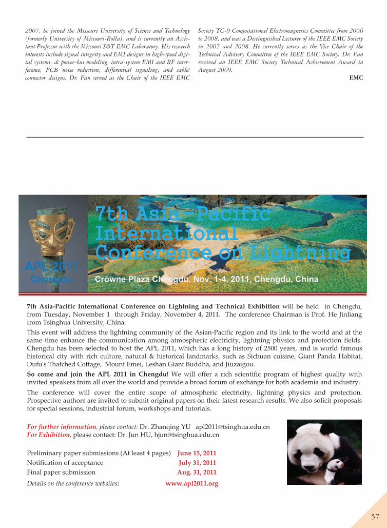
57
2007, he joined the Missouri University of Science and Technology (formerly University of Missouri-Rolla), and is currently an Assis-tant Professor with the Missouri S&T EMC Laboratory. His research interests include signal integrity and EMI designs in high-speed digi-tal systems, dc power-bus modeling, intra-system EMI and RF inter-ference, PCB noise reduction, differential signaling, and cable/connector designs. Dr. Fan served as the Chair of the IEEE EMC
Society TC-9 Computational Electromagnetics Committee from 2006 to 2008, and was a Distinguished Lecturer of the IEEE EMC Society in 2007 and 2008. He currently serves as the Vice Chair of the Technical Advisory Committee of the IEEE EMC Society. Dr. Fan received an IEEE EMC Society Technical Achievement Award in August 2009. EMC
Crowne Plaza Chengdu, Nov. 1-4, 2011, Chengdu, China
7th Asia Pacific International Conference on Lightning and Technical Exhibition will be held in Chengdu,from Tuesday, November 1 through Friday, November 4, 2011. The conference Chairman is Prof. He Jinliangfrom Tsinghua University, China.This event will address the lightning community of the Asian Pacific region and its link to the world and at thesame time enhance the communication among atmospheric electricity, lightning physics and protection fields.Chengdu has been selected to host the APL 2011, which has a long history of 2500 years, and is world famoushistorical city with rich culture, natural & historical landmarks, such as Sichuan cuisine, Giant Panda Habitat,Dufu s Thatched Cottage, Mount Emei, Leshan Giant Buddha, and Jiuzaigou.So come and join the APL 2011 in Chengdu! We will offer a rich scientific program of highest quality withinvited speakers from all over the world and provide a broad forum of exchange for both academia and industry.The conference will cover the entire scope of atmospheric electricity, lightning physics and protection.Prospective authors are invited to submit original papers on their latest research results. We also solicit proposalsfor special sessions, industrial forum, workshops and tutorials.
For further information, please contact: Dr. Zhanqing YU [email protected] Exhibition, please contact: Dr. Jun HU, [email protected]
Preliminary paper submissions (At least 4 pages) June 15, 2011Notification of acceptance July 31, 2011Final paper submission Aug. 31, 2011
Details on the conference websites: www.apl2011.org
APL 2011Chengdu
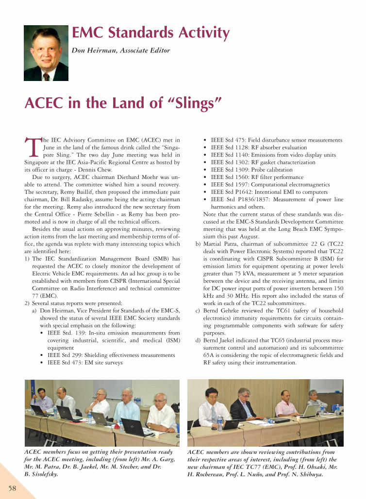
58
EMC Standards ActivityDon Heirman, Associate Editor
ACEC in the Land of “Slings”
The IEC Advisory Committee on EMC (ACEC) met in June in the land of the famous drink called the “Singa-pore Sling.” The two day June meeting was held in
Singapore at the IEC Asia-Pacific Regional Centre as hosted by its officer in charge - Dennis Chew.
Due to surgery, ACEC chairman Diethard Moehr was un-able to attend. The committee wished him a sound recovery. The secretary, Remy Baillif, then proposed the immediate past chairman, Dr. Bill Radasky, assume being the acting chairman for the meeting. Remy also introduced the new secretary from the Central Office - Pierre Sebellin - as Remy has been pro-moted and is now in charge of all the technical officers.
Besides the usual actions on approving minutes, reviewing action items from the last meeting and membership terms of of-fice, the agenda was replete with many interesting topics which are identified here:1) The IEC Standardization Management Board (SMB) has
requested the ACEC to closely monitor the development of Electric Vehicle EMC requirements. An ad hoc group is to be established with members from CISPR (International Special Committee on Radio Interference) and technical committee 77 (EMC).
2) Several status reports were presented:a) Don Heirman, Vice President for Standards of the EMC-S,
showed the status of several IEEE EMC Society standards with special emphasis on the following:• IEEE Std. 139: In-situ emission measurements from
covering industrial, scientific, and medical (ISM) equipment
• IEEE Std 299: Shielding effectiveness measurements• IEEE Std 473: EM site surveys
• IEEE Std 475: Field disturbance sensor measurements• IEEE Std 1128: RF absorber evaluation• IEEE Std 1140: Emissions from video display units• IEEE Std 1302: RF gasket characterization• IEEE Std 1309: Probe calibration • IEEE Std 1560: RF filter performance• IEEE Std 1597: Computational electromagnetics• IEEE Std P1642: Intentional EMI to computers• IEEE Std P1836/1837: Measurement of power line
harmonics and others. Note that the current status of these standards was dis-cussed at the EMC-S Standards Development Committee meeting that was held at the Long Beach EMC Sympo-sium this past August.
b) Martial Patra, chairman of subcommittee 22 G (TC22 deals with Power Electronic Systems) reported that TC22 is coordinating with CISPR Subcommittee B (ISM) for emission limits for equipment operating at power levels greater than 75 kVA, measurement at 5 meter separation between the device and the receiving antenna, and limits for DC power input ports of power inverters between 150 kHz and 30 MHz. His report also included the status of work in each of the TC22 subcommittees.
c) Bernd Gehrke reviewed the TC61 (safety of household electronics) immunity requirements for circuits contain-ing programmable components with software for safety purposes.
d) Bernd Jaekel indicated that TC65 (industrial process mea-surement control and automation) and its subcommittee 65A is considering the topic of electromagnetic fields and RF safety using their instrumentation.
ACEC members focus on getting their presentation ready for the ACEC meeting, including (from left) Mr. A. Garg, Mr. M. Patra, Dr. B. Jaekel, Mr. M. Stecher, and Dr. B. Sisolefsky.
ACEC members are shown reviewing contributions from their respective areas of interest, including (from left) the new chairman of IEC TC77 (EMC), Prof. H. Ohsaki, Mr. H. Rochereau, Prof. L. Nuño, and Prof. N. Shibuya.
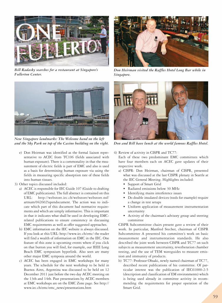
59
e) Don Heirman was identified as the formal liaison repre-sentative to ACEC from TC106 (fields associated with human exposure). There is a commonality in that the mea-surement of electric fields is part of EMC and also is used as a basis for determining human exposure via using the fields in measuring specific absorption rate of these fields into human tissues.
3) Other topics discussed included:a) ACEC is responsible for IEC Guide 107 (Guide to drafting
of EMC publications). The full abstract is contained on this URL: http://webstore.iec.ch/webstore/webstore.nsf/artnum/042602!opendocument. The action was to indi-cate which part of this document had normative require-ments and which are simply informative. This is important in that it indicates what shall be used in developing EMC-related publications to ensure consistency in discussing EMC requirements as well as offer suggested approaches.
b) EMC information on the IEC website is always discussed. If you look at this URL: http://www.iec.ch/emc/ the reader will find a wealth of information on EMC in the IEC. One feature of this zone is upcoming events where if you click on that button you will find, for example, our IEEE Long Beach EMC symposium hyperlink. Also seen are many other major EMC symposia around the world.
c) ACEC has been engaged in EMC workshops for many years. The schedule for the next workshop to be held in Buenos Aires, Argentina was discussed to be held on 12 December 2011 just before the two day ACEC meeting on the 13th and 14th. Past presentations by ACEC members at EMC workshops are on the EMC Zone page. See http://www.iec.ch/emc/emc_news/presentations.htm
4) Review of activity in CISPR and TC77:Each of these two predominant EMC committees which have four members each on ACEC gave updates of their respective work. a) CISPR: Don Heirman, chairman of CISPR, presented
what was discussed at the last CISPR plenary in Seattle at the IEC General Meeting. Highlights included:• Support of Smart Grid• Radiated emissions below 30 MHz• Identifying mains interference issues• Do double insulated devices (tools for example) require
a change in test setups• Uniform application of measurement instrumentation
uncertainty • Activity of the chairman’s advisory group and steering
committeeCISPR Subcommittee chairs present gave a review of their work. In particular, Manfred Stecher, chairman of CISPR Subcommittee A presented his committee’s work on basic measurement and instrumentation standards. He also described the joint work between CISPR and TC77 on such subjects as measurement uncertainty, reverberation chamber testing, and the use of TEM waveguides to measure emis-sion and immunity of products.b) TC77: Professor Ohsaki, newly named chairman of TC77,
described recent publications of his committee. Of par-ticular interest was the publication of IEC61000-2-5 (description and classification of EM environments) which is being used already in committee activity in recom-mending the requirements for proper operation of the Smart Grid.
Bill Radasky searches for a restaurant at Singapore’s Fullerton Center.
New Singapore landmarks: The Welcome hand on the left and the Sky Park on top of the Casino building on the right.
Don Heirman visited the Raffles Hotel Long Bar while in Singapore.
Don and Bill have lunch at the world famous Raffles Hotel.
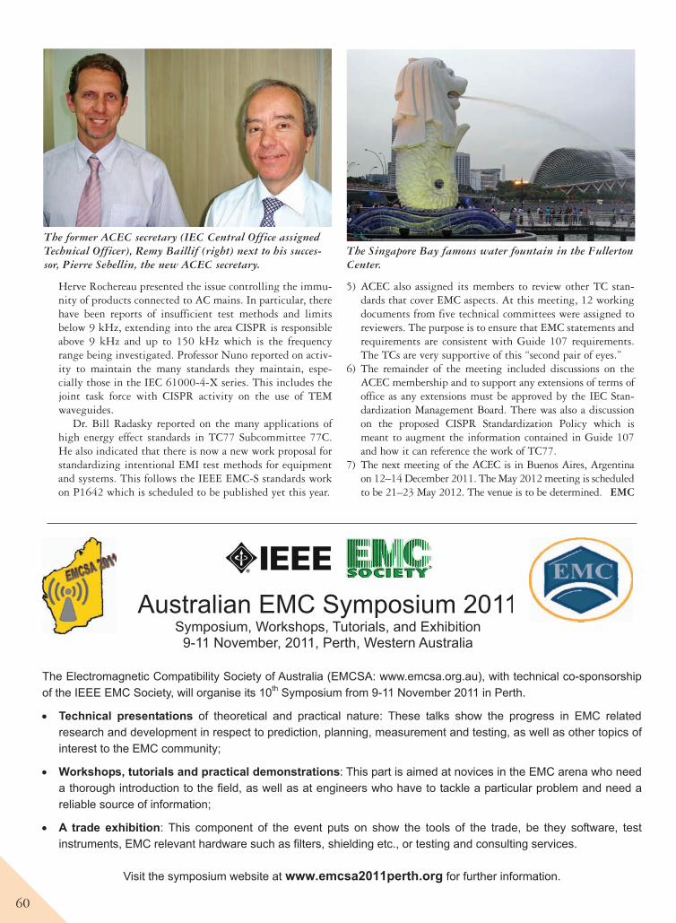
60
Herve Rochereau presented the issue controlling the immu-nity of products connected to AC mains. In particular, there have been reports of insufficient test methods and limits below 9 kHz, extending into the area CISPR is responsible above 9 kHz and up to 150 kHz which is the frequency range being investigated. Professor Nuno reported on activ-ity to maintain the many standards they maintain, espe-cially those in the IEC 61000-4-X series. This includes the joint task force with CISPR activity on the use of TEM waveguides.
Dr. Bill Radasky reported on the many applications of high energy effect standards in TC77 Subcommittee 77C. He also indicated that there is now a new work proposal for standardizing intentional EMI test methods for equipment and systems. This follows the IEEE EMC-S standards work on P1642 which is scheduled to be published yet this year.
5) ACEC also assigned its members to review other TC stan-dards that cover EMC aspects. At this meeting, 12 working documents from five technical committees were assigned to reviewers. The purpose is to ensure that EMC statements and requirements are consistent with Guide 107 requirements. The TCs are very supportive of this “second pair of eyes.”
6) The remainder of the meeting included discussions on the ACEC membership and to support any extensions of terms of office as any extensions must be approved by the IEC Stan-dardization Management Board. There was also a discussion on the proposed CISPR Standardization Policy which is meant to augment the information contained in Guide 107 and how it can reference the work of TC77.
7) The next meeting of the ACEC is in Buenos Aires, Argentina on 12–14 December 2011. The May 2012 meeting is scheduled to be 21–23 May 2012. The venue is to be determined. EMC
The former ACEC secretary (IEC Central Office assigned Technical Officer), Remy Baillif (right) next to his succes-sor, Pierre Sebellin, the new ACEC secretary.
The Singapore Bay famous water fountain in the Fullerton Center.
Australian EMC Symposium 2011Symposium, Workshops, Tutorials, and Exhibition
9-11 November, 2011, Perth, Western Australia
The Electromagnetic Compatibility Society of Australia (EMCSA: www.emcsa.org.au), with technical co-sponsorship of the IEEE EMC Society, will organise its 10th Symposium from 9-11 November 2011 in Perth.
Technical presentations of theoretical and practical nature: These talks show the progress in EMC related research and development in respect to prediction, planning, measurement and testing, as well as other topics of interest to the EMC community;
Workshops, tutorials and practical demonstrations: This part is aimed at novices in the EMC arena who need a thorough introduction to the field, as well as at engineers who have to tackle a particular problem and need a reliable source of information;
A trade exhibition: This component of the event puts on show the tools of the trade, be they software, test instruments, EMC relevant hardware such as filters, shielding etc., or testing and consulting services.
Visit the symposium website at www.emcsa2011perth.org for further information.
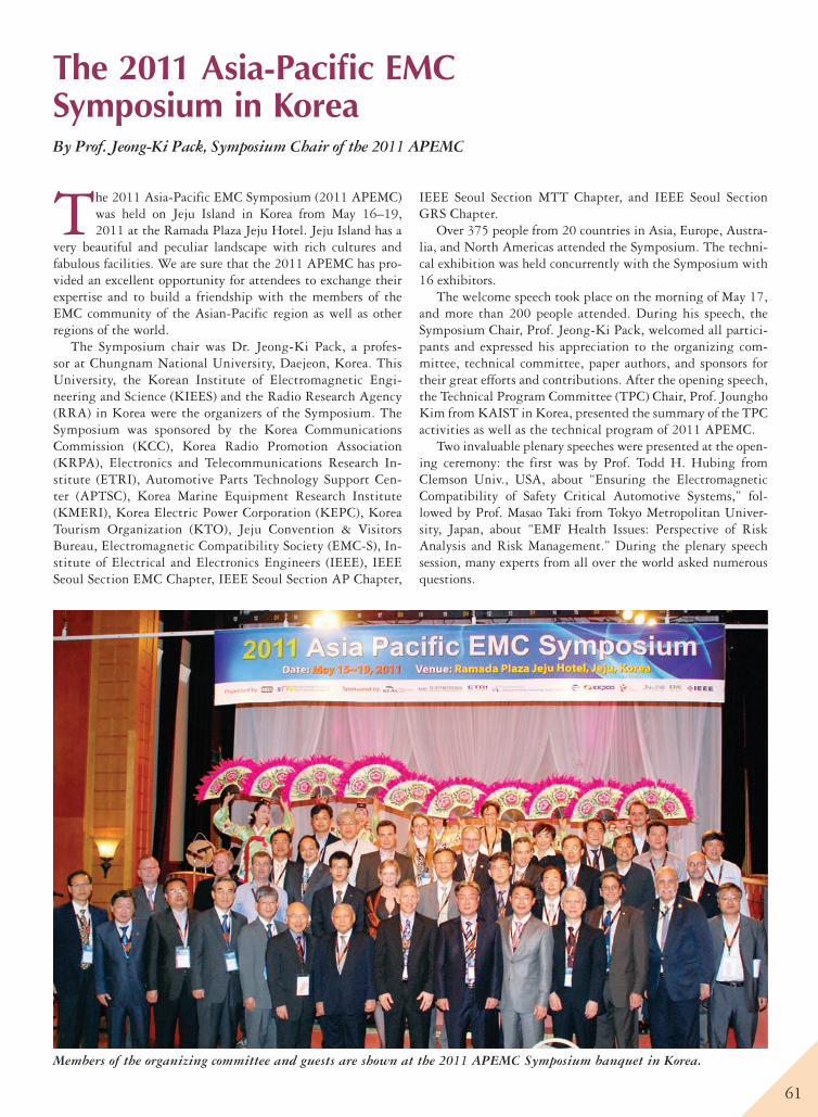
61
The 2011 Asia-Pacific EMC Symposium in KoreaBy Prof. Jeong-Ki Pack, Symposium Chair of the 2011 APEMC
The 2011 Asia-Pacific EMC Symposium (2011 APEMC) was held on Jeju Island in Korea from May 16–19, 2011 at the Ramada Plaza Jeju Hotel. Jeju Island has a
very beautiful and peculiar landscape with rich cultures and fabulous facilities. We are sure that the 2011 APEMC has pro-vided an excellent opportunity for atten dees to exchange their expertise and to build a friendship with the members of the EMC community of the Asian-Pacific region as well as other regions of the world.
The Symposium chair was Dr. Jeong-Ki Pack, a profes-sor at Chungnam National University, Daejeon, Korea. This University, the Korean Institute of Electromagnetic Engi-neering and Science (KIEES) and the Radio Research Agency (RRA) in Korea were the organizers of the Symposium. The Symposium was sponsored by the Korea Communications Commission (KCC), Korea Radio Promotion Association (KRPA), Electronics and Telecommunications Research In-stitute (ETRI), Automotive Parts Technology Support Cen-ter (APTSC), Korea Marine Equipment Research Institute (KMERI), Korea Electric Power Corporation (KEPC), Korea Tourism Organization (KTO), Jeju Convention & Visitors Bureau, Electromagnetic Compatibility Society (EMC-S), In-stitute of Electrical and Electronics Engineers (IEEE), IEEE Seoul Section EMC Chapter, IEEE Seoul Section AP Chapter,
IEEE Seoul Section MTT Chapter, and IEEE Seoul Section GRS Chapter.
Over 375 people from 20 countries in Asia, Europe, Austra-lia, and North Americas attended the Symposium. The techni-cal exhibition was held concurrently with the Symposium with 16 exhibitors.
The welcome speech took place on the morning of May 17, and more than 200 people attended. During his speech, the Symposium Chair, Prof. Jeong-Ki Pack, welcomed all partici-pants and expressed his appreciation to the organizing com-mittee, technical committee, paper authors, and sponsors for their great efforts and contributions. After the opening speech, the Technical Program Committee (TPC) Chair, Prof. Joungho Kim from KAIST in Korea, presented the summary of the TPC activities as well as the technical program of 2011 APEMC.
Two invaluable plenary speeches were presented at the open-ing ceremony: the first was by Prof. Todd H. Hubing from Clemson Univ., USA, about “Ensuring the Electromagnetic Compatibility of Safety Critical Automotive Systems,” fol-lowed by Prof. Masao Taki from Tokyo Metropolitan Univer-sity, Japan, about “EMF Health Issues: Perspective of Risk Analysis and Risk Management.” During the plenary speech session, many experts from all over the world asked numerous questions.
Members of the organizing committee and guests are shown at the 2011 APEMC Symposium banquet in Korea.
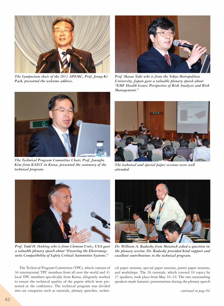
62
The Technical Program Committee (TPC), which consists of 36 international TPC members from all over the world and 41 local TPC members specifically from Korea, diligently worked to ensure the technical quality of the papers which were pre-sented at the conference. The technical program was divided into six categories such as tutorials, plenary speeches, techni-
cal paper sessions, special paper sessions, poster paper sessions, and workshops. The 26 tutorials, which covered 10 topics by 27 speakers, took place from May 16–19. The two outstanding speakers made fantastic presentations during the plenary speech
The Symposium chair of the 2011 APEMC, Prof. Jeong-Ki Pack, presented the welcome address.
The Technical Program Committee Chair, Prof. Joungho Kim from KAIST in Korea, presented the summary of the technical program.
Prof. Todd H. Hubing who is from Clemson Univ., USA gave a valuable plenary speech about “Ensuring the Electromag-netic Compatibility of Safety Critical Automotive Systems.”
Prof. Masao Taki who is from the Tokyo Metropolitan University, Japan gave a valuable plenary speech about “EMF Health Issues: Perspective of Risk Analysis and Risk Management.”
Dr. William A. Radasky from Metatech asked a question in the plenary session. Dr. Radasky provided kind support and excellent contributions to the technical program.
The technical and special paper sessions were well attended.
continued on page 64
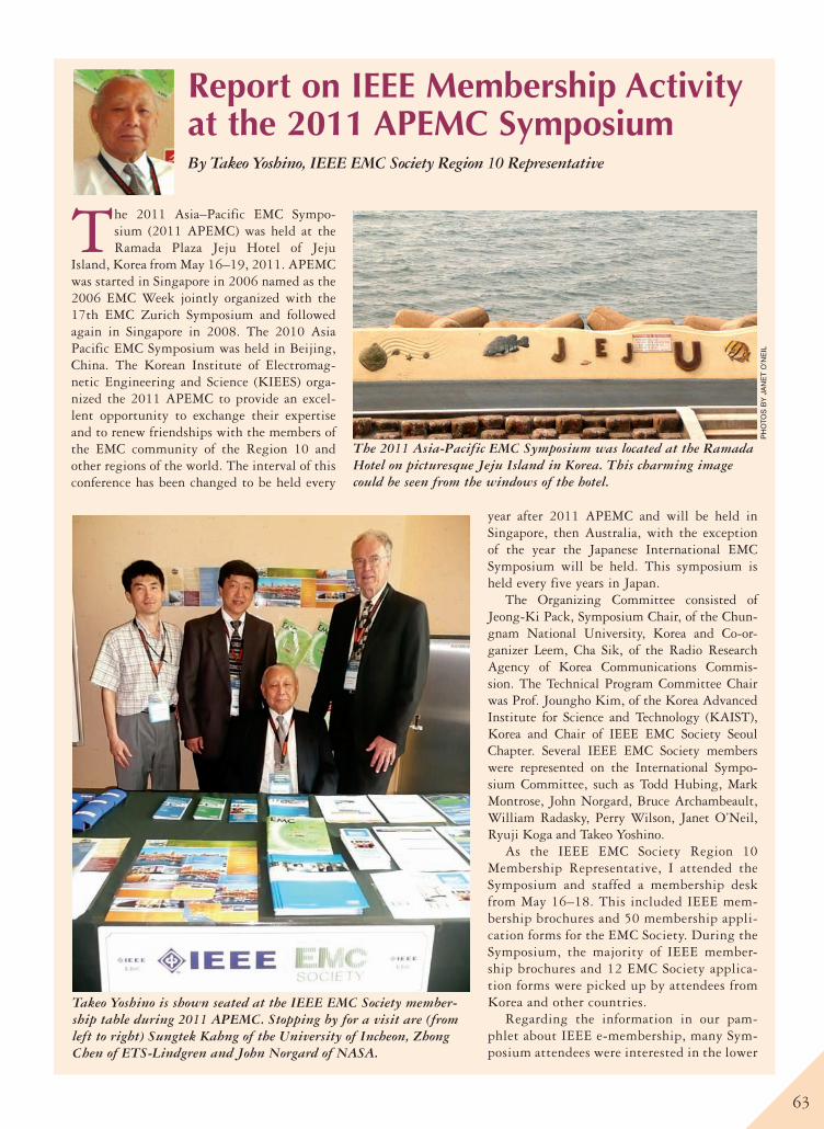
63
The 2011 Asia–Pacific EMC Sympo-sium (2011 APEMC) was held at the Ramada Plaza Jeju Hotel of Jeju
Island, Korea from May 16–19, 2011. APEMC was started in Singapore in 2006 named as the 2006 EMC Week jointly organized with the 17th EMC Zurich Symposium and followed again in Singapore in 2008. The 2010 Asia Pacific EMC Symposium was held in Beijing, China. The Korean Institute of Electromag-netic Engineering and Science (KIEES) orga-nized the 2011 APEMC to provide an excel-lent opportunity to exchange their expertise and to renew friendships with the members of the EMC community of the Region 10 and other regions of the world. The interval of this conference has been changed to be held every
year after 2011 APEMC and will be held in Singapore, then Australia, with the exception of the year the Japanese International EMC Symposium will be held. This symposium is held every five years in Japan.
The Organizing Committee consisted of Jeong-Ki Pack, Symposium Chair, of the Chun-gnam National University, Korea and Co-or-ganizer Leem, Cha Sik, of the Radio Research Agency of Korea Communications Commis-sion. The Technical Program Committee Chair was Prof. Joungho Kim, of the Korea Advanced Institute for Science and Technology (KAIST), Korea and Chair of IEEE EMC Society Seoul Chapter. Several IEEE EMC Society members were represented on the International Sympo-sium Committee, such as Todd Hubing, Mark Montrose, John Norgard, Bruce Archambeault, William Radasky, Perry Wilson, Janet O’Neil, Ryuji Koga and Takeo Yoshino.
As the IEEE EMC Society Region 10 Membership Representative, I attended the Symposium and staffed a membership desk from May 16–18. This included IEEE mem-bership brochures and 50 membership appli-cation forms for the EMC Society. During the Symposium, the majority of IEEE member-ship brochures and 12 EMC Society applica-tion forms were picked up by attendees from Korea and other countries.
Regarding the information in our pam-phlet about IEEE e-membership, many Sym-posium attendees were interested in the lower
Report on IEEE Membership Activity at the 2011 APEMC SymposiumBy Takeo Yoshino, IEEE EMC Society Region 10 Representative
Takeo Yoshino is shown seated at the IEEE EMC Society member-ship table during 2011 APEMC. Stopping by for a visit are (from left to right) Sungtek Kahng of the University of Incheon, Zhong Chen of ETS-Lindgren and John Norgard of NASA.
The 2011 Asia-Pacific EMC Symposium was located at the Ramada Hotel on picturesque Jeju Island in Korea. This charming image could be seen from the windows of the hotel.
Ph
oto
s b
y J
an
et
o’n
eil
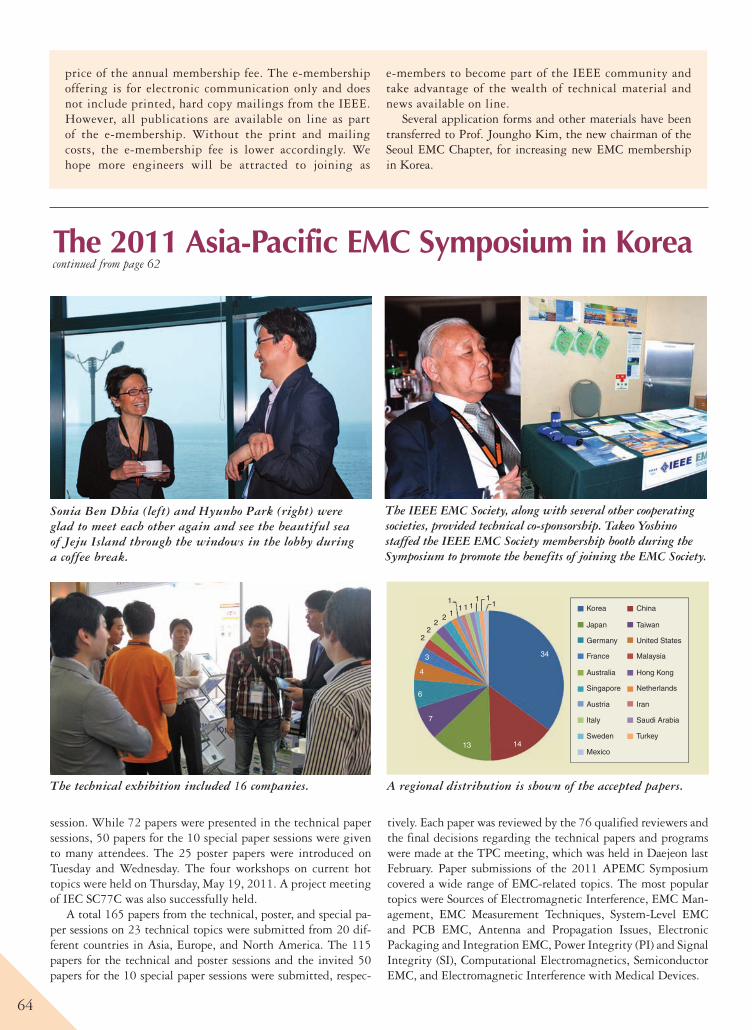
64
Sonia Ben Dhia (left) and Hyunho Park (right) were glad to meet each other again and see the beautiful sea of Jeju Island through the windows in the lobby during a coffee break.
2
3
4
6
7
13 14
34
22
2 1
11 1 1
1 11
Korea
Japan
Germany
France
Australia
Singapore
Austria
Italy
Sweden
China
Taiwan
United States
Malaysia
Hong Kong
Netherlands
Iran
Saudi Arabia
Turkey
Mexico
A regional distribution is shown of the accepted papers.
price of the annual membership fee. The e-membership offering is for electronic communication only and does not include printed, hard copy mailings from the IEEE. However, all publications are available on line as part of the e-membership. Without the print and mailing costs, the e-membership fee is lower accordingly. We hope more engineers will be attracted to joining as
e-members to become part of the IEEE community and take advantage of the wealth of technical material and news available on line.
Several application forms and other materials have been transferred to Prof. Joungho Kim, the new chairman of the Seoul EMC Chapter, for increasing new EMC membership in Korea.
session. While 72 papers were presented in the technical paper sessions, 50 papers for the 10 special paper sessions were given to many attendees. The 25 poster papers were introduced on Tuesday and Wednesday. The four workshops on current hot topics were held on Thursday, May 19, 2011. A project meeting of IEC SC77C was also successfully held.
A total 165 papers from the technical, poster, and special pa-per sessions on 23 technical topics were submitted from 20 dif-ferent countries in Asia, Europe, and North America. The 115 papers for the technical and poster sessions and the invited 50 papers for the 10 special paper sessions were submitted, respec-
tively. Each paper was reviewed by the 76 qualified reviewers and the final decisions regarding the technical papers and programs were made at the TPC meeting, which was held in Daejeon last February. Paper submissions of the 2011 APEMC Symposium covered a wide range of EMC-related topics. The most popular topics were Sources of Electromagnetic Interference, EMC Man-agement, EMC Measurement Techniques, System-Level EMC and PCB EMC, Antenna and Propagation Issues, Electronic Packaging and Integration EMC, Power Integrity (PI) and Signal Integrity (SI), Computational Electromagnetics, Semiconductor EMC, and Electromagnetic Interference with Medical Devices.
The 2011 Asia-Pacific EMC Symposium in Koreacontinued from page 62
The technical exhibition included 16 companies.
The IEEE EMC Society, along with several other cooperating societies, provided technical co-sponsorship. Takeo Yoshino staffed the IEEE EMC Society membership booth during the Symposium to promote the benefits of joining the EMC Society.
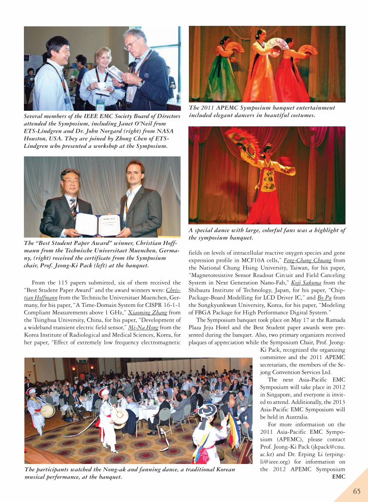
65
From the 115 papers submitted, six of them received the “Best Student Paper Award” and the award winners were: Chris-tian Hoffmann from the Technische Universitaet Muenchen, Ger-many, for his paper, “A Time-Domain System for CISPR 16-1-1 Compliant Measurements above 1 GHz,” Xiaoming Zhang from the Tsinghua University, China, for his paper, “Development of a wideband transient electric field sensor,” Mi-Na Hong from the Korea Institute of Radiological and Medical Sciences, Korea, for her paper, “Effect of extremely low frequency electromagnetic
fields on levels of intracellular reactive oxygen species and gene expression profile in MCF10A cells,” Feng-Chang Chuang from the National Chung Hsing University, Taiwan, for his paper, “Magnetoresistive Sensor Readout Circuit and Field Canceling System in Next Generation Nano-Fab,” Koji Sakuma from the Shibaura Institute of Technology, Japan, for his paper, “Chip-Package-Board Modelling for LCD Driver IC,” and Bo Pu from the Sungkyunkwan University, Korea, for his paper, “Modeling of FBGA Package for High Performance Digital System.”
The Symposium banquet took place on May 17 at the Ramada Plaza Jeju Hotel and the Best Student paper awards were pre-sented during the banquet. Also, two primary organizers received plaques of appreciation while the Symposium Chair, Prof. Jeong-
Ki Pack, recognized the organizing committee and the 2011 APEMC secretariats, the members of the Se-jong Convention Services Ltd.
The next Asia-Pacific EMC Symposium will take place in 2012 in Singapore, and everyone is invit-ed to attend. Additionally, the 2013 Asia-Pacific EMC Symposium will be held in Australia.
For more information on the 2011 Asia-Pacific EMC Sympo-sium (APEMC), please contact Prof. Jeong-Ki Pack ([email protected]) and Dr. Erping Li ([email protected]) for information on the 2012 APEMC Symposium EMC
Several members of the IEEE EMC Society Board of Directors attended the Symposium, including Janet O’Neil from ETS-Lindgren and Dr. John Norgard (right) from NASA Houston, USA. They are joined by Zhong Chen of ETS-Lindgren who presented a workshop at the Symposium.
The “Best Student Paper Award” winner, Christian Hoff-mann from the Technische Universitaet Muenchen, Germa-ny, (right) received the certificate from the Symposium chair, Prof. Jeong-Ki Pack (left) at the banquet.
A special dance with large, colorful fans was a highlight of the symposium banquet.
The participants watched the Nong-ak and fanning dance, a traditional Korean musical performance, at the banquet.
The 2011 APEMC Symposium banquet entertainment included elegant dancers in beautiful costumes.
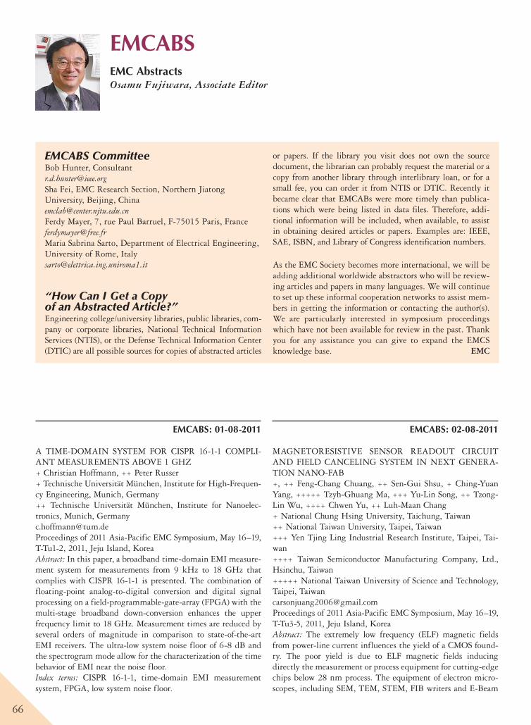
66
EMCABSEMC AbstractsOsamu Fujiwara, Associate Editor
EMCABS CommitteeBob Hunter, [email protected] Fei, EMC Research Section, Northern Jiatong University, Beijing, [email protected] Mayer, 7, rue Paul Barruel, F-75015 Paris, [email protected] Sabrina Sarto, Department of Electrical Engineering, University of Rome, [email protected]
“How Can I Get a Copy of an Abstracted Article?”Engineering college/university libraries, public libraries, com-pany or corporate libraries, National Technical Information Services (NTIS), or the Defense Technical Information Center (DTIC) are all possible sources for copies of abstracted articles
or papers. If the library you visit does not own the source document, the librarian can probably request the material or a copy from another library through interlibrary loan, or for a small fee, you can order it from NTIS or DTIC. Recently it became clear that EMCABs were more timely than publica-tions which were being listed in data files. Therefore, addi-tional information will be included, when available, to assist in obtaining desired articles or papers. Examples are: IEEE, SAE, ISBN, and Library of Congress identification numbers.
As the EMC Society becomes more international, we will be adding additional worldwide abstractors who will be review-ing articles and papers in many languages. We will continue to set up these informal cooperation networks to assist mem-bers in getting the information or contacting the author(s). We are particularly interested in symposium proceedings which have not been available for review in the past. Thank you for any assistance you can give to expand the EMCS knowledge base. EMC
EMCABS: 01-08-2011
A TIME-DOMAIN SYSTEM FOR CISPR 16-1-1 COMPLI-ANT MEASUREMENTS ABOVE 1 GHZ+ Christian Hoffmann, ++ Peter Russer+ Technische Universität München, Institute for High-Frequen-cy Engineering, Munich, Germany++ Technische Universität München, Institute for Nanoelec-tronics, Munich, [email protected] of 2011 Asia-Pacific EMC Symposium, May 16–19, T-Tu1-2, 2011, Jeju Island, KoreaAbstract: In this paper, a broadband time-domain EMI measure-ment system for measurements from 9 kHz to 18 GHz that complies with CISPR 16-1-1 is presented. The combination of floating-point analog-to-digital conversion and digital signal processing on a field-programmable-gate-array (FPGA) with the multi-stage broadband down-conversion enhances the upper frequency limit to 18 GHz. Measurement times are reduced by several orders of magnitude in comparison to state-of-the-art EMI receivers. The ultra-low system noise floor of 6-8 dB and the spectrogram mode allow for the characterization of the time behavior of EMI near the noise floor.Index terms: CISPR 16-1-1, time-domain EMI measurement system, FPGA, low system noise floor.
EMCABS: 02-08-2011
MAGNETORESISTIVE SENSOR READOUT CIRCUIT AND FIELD CANCELING SYSTEM IN NEXT GENERA-TION NANO-FAB+, ++ Feng-Chang Chuang, ++ Sen-Gui Shsu, + Ching-Yuan Yang, +++++ Tzyh-Ghuang Ma, +++ Yu-Lin Song, ++ Tzong-Lin Wu, ++++ Chwen Yu, ++ Luh-Maan Chang+ National Chung Hsing University, Taichung, Taiwan ++ National Taiwan University, Taipei, Taiwan +++ Yen Tjing Ling Industrial Research Institute, Taipei, Tai-wan ++++ Taiwan Semiconductor Manufacturing Company, Ltd., Hsinchu, Taiwan +++++ National Taiwan University of Science and Technology, Taipei, [email protected] of 2011 Asia-Pacific EMC Symposium, May 16–19, T-Tu3-5, 2011, Jeju Island, KoreaAbstract: The extremely low frequency (ELF) magnetic fields from power-line current influences the yield of a CMOS found-ry. The poor yield is due to ELF magnetic fields inducing directly the measurement or process equipment for cutting-edge chips below 28 nm process. The equipment of electron micro-scopes, including SEM, TEM, STEM, FIB writers and E-Beam
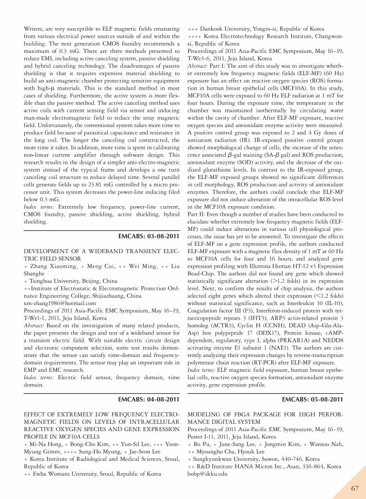
67
Writers, are very susceptible to ELF magnetic fields emanating from various electrical power sources outside of and within the building. The next generation CMOS foundry recommends a maximum of 0.3 mG. There are three methods presented to reduce EMI, including active canceling system, passive shielding and hybrid canceling technology. The disadvantages of passive shielding is that it requires expensive material shielding to build an anti-magnetic chamber protecting sensitive equipment with high-µ materials. This is the standard method in most cases of shielding. Furthermore, the active system is more flex-ible than the passive method. The active canceling method uses active coils with current sensing field via sensor and inducing man-made electromagnetic field to reduce the stray magnetic field. Unfortunately, the conventional system takes more time to produce field because of parasitical capacitance and resistance in the long coil. The longer the canceling coil constructed, the more time it takes. In addition, more time is spent in calibrating non-linear current amplifier through software design. This research results in the design of a simpler anti-electro-magnetic system instead of the typical frame and develops a one turn canceling coil structure to reduce delayed time. Several parallel cells generate fields up to 23.81 mG controlled by a micro pro-cessor unit. This system decreases the power-line inducing filed below 0.3 mG.Index terms: Extremely low frequency, power-line current, CMOS foundry, passive shielding, active shielding, hybrid shielding.
EMCABS: 03-08-2011
DEVELOPMENT OF A WIDEBAND TRANSIENT ELEC-TRIC FIELD SENSOR+ Zhang Xiaoming, + Meng Cui, ++ Wei Ming, ++ Liu Shanghe+ Tsinghua University, Beijing, China++Institute of Electrostatic & Electromagnetic Protection Ord-nance Engineering College, Shijiazhuang, [email protected] of 2011 Asia-Pacific EMC Symposium, May 16–19, T-We1-1, 2011, Jeju Island, KoreaAbstract: Based on the investigation of many related products, the paper presents the design and test of a wideband sensor for a transient electric field. With suitable electric circuit design and electronic component selection, some test results demon-strate that the sensor can satisfy time-domain and frequency-domain requirements. The sensor may play an important role in EMP and EMC research.Index terms: Electric field sensor, frequency domain, time domain.
EMCABS: 04-08-2011
EFFECT OF EXTREMELY LOW FREQUENCY ELECTRO-MAGNETIC FIELDS ON LEVELS OF INTRACELLULAR REACTIVE OXYGEN SPECIES AND GENE EXPRESSION PROFILE IN MCF10A CELLS+ Mi-Na Hong, + Bong-Cho Kim, ++ Yun-Sil Lee, +++ Yoon-Myung Gimm, ++++ Sung-Ho Myung, + Jae-Seon Lee+ Korea Institute of Radiological and Medical Sciences, Seoul, Republic of Korea++ Ewha Womans University, Seoul, Republic of Korea
+++ Dankook University, Yongin-si, Republic of Korea++++ Korea Electrotechnology Research Institute, Changwon-si, Republic of KoreaProceedings of 2011 Asia-Pacific EMC Symposium, May 16–19, T-We3-6, 2011, Jeju Island, KoreaAbstract: Part I: The aim of this study was to investigate wheth-er extremely low frequency magnetic fields (ELF-MF) (60 Hz) exposure has an effect on reactive oxygen species (ROS) forma-tion in human breast epithelial cells (MCF10A). In this study, MCF10A cells were exposed to 60 Hz ELF radiation at 1 mT for four hours. During the exposure time, the temperature in the chamber was maintained isothermally by circulating water within the cavity of chamber. After ELF-MF exposure, reactive oxygen species and antioxidant enzyme activity were measured. A positive control group was exposed to 2 and 4 Gy doses of ionization radiation (IR). IR-exposed positive control groups showed morphological change of cells, the increase of the senes-cence associated b-gal staining (SA-b gal) and ROS production, antioxidant enzyme (SOD) activity, and the decrease of the oxi-dized glutathione levels. In contrast to the IR-exposed group, the ELF-MF exposed groups showed no significant differences in cell morphology, ROS production and activity of antioxidant enzymes. Therefore, the authors could conclude that ELF-MF exposure did not induce alteration of the intracellular ROS level in the MCF10A exposure condition.Part II: Even though a number of studies have been conducted to elucidate whether extremely low frequency magnetic fields (ELF-MF) could induce alterations in various cell physiological pro-cesses, the issue has yet to be answered. To investigate the effects of ELF-MF on a gene expression profile, the authors conducted ELF-MF exposure with a magnetic flux density of 1 mT at 60 Hz to MCF10A cells for four and 16 hours, and analyzed gene expression profiling with Illumina Human HT-12 v3 Expression Bead-Chip. The authors did not found any gene which showed statistically significant alteration (.1.2 folds) in its expression level. Next, to confirm the results of chip analysis, the authors selected eight genes which altered their expression (,1.2 folds) without statistical significance, such as Interleukin 10 (IL-10), Coagulation factor III (F3), Interferon-induced protein with tet-ratricopeptide repeats 3 (IFIT3), ARP3 actin-related protein 3 homolog (ACTR3), Cyclin H (CCNH), DEAD (Asp-Glu-Ala-Asp) box polypeptide 17 (DDX17), Protein kinase, cAMP-dependent, regulatory, type I, alpha (PRKAR1A) and NEDD8 activating enzyme E1 subunit 1 (NAE1). The authors are cur-rently analyzing their expression changes by reverse-transcription polymerase chain reaction (RT-PCR) after ELF-MF exposure.Index terms: ELF magnetic field exposure, human breast epithe-lial cells, reactive oxygen species formation, antioxidant enzyme activity, gene expression profile.
EMCABS: 05-08-2011
MODELING OF FBGA PACKAGE FOR HIGH PERFOR-MANCE DIGITAL SYSTEMProceedings of 2011 Asia-Pacific EMC Symposium, May 16–19, Poster I-11, 2011, Jeju Island, Korea+ Bo Pu, + June-Sang Lee, + Jongmin Kim, + Wansoo Nah, ++ Myoungho Cha, Hyouk Lee+ Sungkyunkwan University, Suwon, 440-746, Korea++ R&D Institute HANA Micron Inc., Asan, 336-864, [email protected]
68
Abstract: This paper presents a novel model for the complete signal paths of a 484 pins Fine-Pitch Ball Grid Array (FBGA) package with parameters extracted from an improved Partial Element Equivalent Circuit (PEEC) method. The exact struc-ture of coupled bonding wires with non-orthogonal elements, vias including nearby ground island, and package traces having 45o bend are combined in an analytical interconnect model for higher accuracy. Measured S-parameters validated the proposed electrical model, and the electrical characteristics of a FBGA package have been successfully analyzed.Index terms: Component, equivalent circuit modeling, FBGA package, PEEC, electrical characterization, bonding wire.
EMCABS: 06-08-2011
CHIP-PACKAGE-BOARD MODELLING FOR LCD DRIV-ER ICKoji Sakuma, Toshi SudoShibaura Institute of Technology, 3-7-5, Toyosu, Koto-ku, Tokyo, [email protected] of 2011 Asia-Pacific EMC Symposium, May 16–19, Poster II-12, 2011, Jeju Island, KoreaAbstract: Electromagnetic interference (EMI) from a liquid crys-tal display (LCD) has become more difficult as the pixel scan-ning speed becomes faster and the LCD panel becomes larger. In this paper, a chip-package-board model was established for the power distribution network (PDN) of the whole system. Then, switching currents were simulated by using the model. The effect of on-chip decoupling capacitance in particular was esti-mated for the two typical frequencies. One was a relatively slower frequency, corresponding to the line scanning speed. Another was a higher frequency of 50 MHz, corresponding to the pixel scanning speed.Index terms: Electromagnetic interference, liquid crystal display, chip-package-board model, switching current, simulation.
EMCABS: 07-08-2011
MODELING, SIMULATION, AND MEASUREMENT OF COMMON-MODE CURRENT FOR AUTOMOTIVE ELEC-TROMAGNETIC COMPATIBILITY+ Shingo Okada, ++ Takanori Uno, + Hideki Asai+ Shizuoka University, Hamamatsu-shi, 432-8561 Japan++ DENSO CORPORATION, Kariya-shi, Aichi, 448-8661 [email protected] of 2011 Asia-Pacific EMC Symposium, May 16–19, T-We5-2, 2011, Jeju Island, KoreaAbstract: In this paper, the authors introduce a practical equiva-lent circuit modeling for automotive electromagnetic compati-bility (EMC). The modeling covers the inside of an integrated circuit (IC) on a printed circuit board (PCB), an attached wire harness, and surrounding parasitic elements. The equivalent circuit is suitable for the simulation of the common-mode cur-rent caused by switching devices in the IC, and thereby becom-ing the electromagnetic interference (EMI) source among auto-motive electronic devices. With the proposed equivalent circuit, more detailed and valid simulation and optimization can be performed for the common-mode noise reduction. Adequacy of the model is shown by confirming that the simulation results of
the equivalent circuit agree with the actual measurement results of an evaluation board.Index terms: EMI reduction, common-mode current, ECU, opti-mization algorithm.
EMCABS: 08-08-2011
EFFECT OF A SHELTER ON SVSWR VALIDATION AT OATS+ Jungyu Yang, +++ Seungwoo Lee, ++ Hongsik Keum, +++ Nam Kim+ Radio Research Agency, Seoul, Korea++ Korea Radio Promotion Association, Seoul, Korea+++ Chungbuk National University, Cheongju-si, Chungbuk, [email protected] of 2011 Asia-Pacific EMC Symposium, May 16–19, T-We2-7, 2011, Jeju Island, KoreaAbstract: In this paper, the authors researched the effect of a shelter on the site voltage standing wave ratio (SVSWR) verifi-cation of an OATS (open area test site). The result of the SVSWR measurement taken outside the shelter at the OATS-A was recorded as 4.4 dB or less and that at the OATS-B was recorded as 4.65 dB or less. Thus, it is concluded that the mea-sured values outside the shelter at both test sites did not exceed the limit value of 6 dB. However, the results taken inside the shelter at both sites were recorded as 6.61 dB or less and 25.63 dB or less, respectively. Thus, it is concluded that the measure-ment results obtained inside of the shelter indicate that reflect-ed waves are generated inside the shelter. The authors verified that the site validation requirements will be satisfied, if it were more than 6 m away from an obstacle and the absorbers were located where they can fully absorb the reflection waves. Fur-ther consideration should be given with regard to the building materials of a shelter because the current shelter might not provide a satisfactory test environment over a frequency of 1 GHz or above.Index terms: Site-VSWR, shelter, OATS.
EMCABS: 09-08-2011
VERTICALLY ALTERNATING IMPEDANCE ELECTRO-MAGNETIC BANDGAP (VAI-EBG) STRUCTURE FOR NOISE MITIGATION IN MULTI-LAYER PCBSMyunghoi Kim, Kyoungchoul Koo, Sunkyu Kong, Bumhee Bae, Sangrok Lee, Joungho KimKAIST, 373-1 Guseong-dong, Yuseong-gu, Daejeon 305-701, Republic of [email protected] of 2011 Asia-Pacific EMC Symposium, May 16–19, S-Tu2-3, 2011, Jeju Island, KoreaAbstract: In this paper, the authors propose a vertically alternat-ing impedance electromagnetic bandgap (VAI-EBG) structure for significant mitigation of power/ground noise in multi-layer printed circuit boards (PCBs), which greatly improves the power/ground noise suppression in the frequency range 800MHz to 10GHz with -50dB isolation. The significant improvement of power/ground noise isolation is enabled using vertically alter-nating impedance which is implemented by vertical branches and vertically-distributed patches. Test vehicles are fabricated using standard PCB process and the power/ground noise
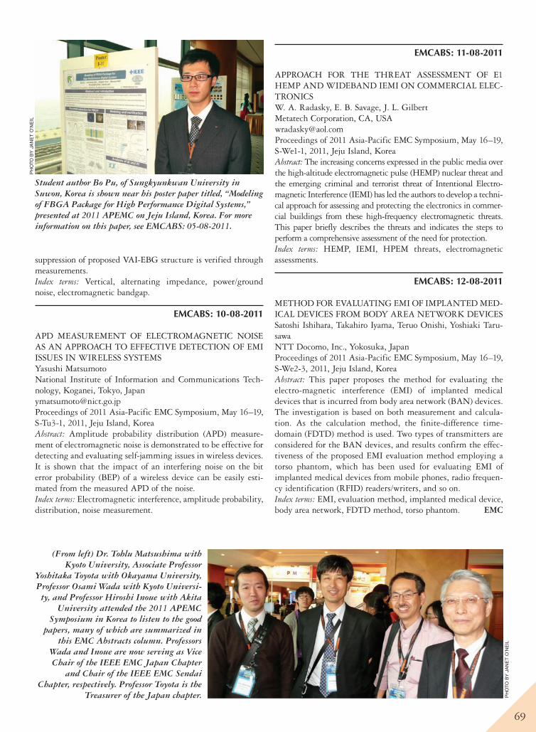
69
suppression of proposed VAI-EBG structure is verified through measurements.Index terms: Vertical, alternating impedance, power/ground noise, electromagnetic bandgap.
EMCABS: 10-08-2011
APD MEASUREMENT OF ELECTROMAGNETIC NOISE AS AN APPROACH TO EFFECTIVE DETECTION OF EMI ISSUES IN WIRELESS SYSTEMSYasushi MatsumotoNational Institute of Information and Communications Tech-nology, Koganei, Tokyo, [email protected] of 2011 Asia-Pacific EMC Symposium, May 16–19, S-Tu3-1, 2011, Jeju Island, KoreaAbstract: Amplitude probability distribution (APD) measure-ment of electromagnetic noise is demonstrated to be effective for detecting and evaluating self-jamming issues in wireless devices. It is shown that the impact of an interfering noise on the bit error probability (BEP) of a wireless device can be easily esti-mated from the measured APD of the noise.Index terms: Electromagnetic interference, amplitude probability, distribution, noise measurement.
EMCABS: 11-08-2011
APPROACH FOR THE THREAT ASSESSMENT OF E1 HEMP AND WIDEBAND IEMI ON COMMERCIAL ELEC-TRONICSW. A. Radasky, E. B. Savage, J. L. Gilbert Metatech Corporation, CA, [email protected] of 2011 Asia-Pacific EMC Symposium, May 16–19, S-We1-1, 2011, Jeju Island, KoreaAbstract: The increasing concerns expressed in the public media over the high-altitude electromagnetic pulse (HEMP) nuclear threat and the emerging criminal and terrorist threat of Intentional Electro-magnetic Interference (IEMI) has led the authors to develop a techni-cal approach for assessing and protecting the electronics in commer-cial buildings from these high-frequency electromagnetic threats. This paper briefly describes the threats and indicates the steps to perform a comprehensive assessment of the need for protection.Index terms: HEMP, IEMI, HPEM threats, electromagnetic assessments.
EMCABS: 12-08-2011
METHOD FOR EVALUATING EMI OF IMPLANTED MED-ICAL DEVICES FROM BODY AREA NETWORK DEVICES Satoshi Ishihara, Takahiro Iyama, Teruo Onishi, Yoshiaki Taru-sawa NTT Docomo, Inc., Yokosuka, JapanProceedings of 2011 Asia-Pacific EMC Symposium, May 16–19, S-We2-3, 2011, Jeju Island, KoreaAbstract: This paper proposes the method for evaluating the electro-magnetic interference (EMI) of implanted medical devices that is incurred from body area network (BAN) devices. The investigation is based on both measurement and calcula-tion. As the calculation method, the finite-difference time-domain (FDTD) method is used. Two types of transmitters are considered for the BAN devices, and results confirm the effec-tiveness of the proposed EMI evaluation method employing a torso phantom, which has been used for evaluating EMI of implanted medical devices from mobile phones, radio frequen-cy identification (RFID) readers/writers, and so on.Index terms: EMI, evaluation method, implanted medical device, body area network, FDTD method, torso phantom. EMC
Student author Bo Pu, of Sungkyunkwan University in Suwon, Korea is shown near his poster paper titled, “Modeling of FBGA Package for High Performance Digital Systems,” presented at 2011 APEMC on Jeju Island, Korea. For more information on this paper, see EMCABS: 05-08-2011.
PH
OTO
BY
JA
NE
T O
’NE
IL
(From left) Dr. Tohlu Matsushima with Kyoto University, Associate Professor
Yoshitaka Toyota with Okayama University, Professor Osami Wada with Kyoto Universi-ty, and Professor Hiroshi Inoue with Akita
University attended the 2011 APEMC Symposium in Korea to listen to the good
papers, many of which are summarized in this EMC Abstracts column. Professors
Wada and Inoue are now serving as Vice Chair of the IEEE EMC Japan Chapter
and Chair of the IEEE EMC Sendai Chapter, respectively. Professor Toyota is the
Treasurer of the Japan chapter. PH
OTO
BY
JA
NE
T O
’NE
IL
70
Bylaws ChangesBy Todd Hubing, Past President of the IEEE EMC Society
One of the outcomes of the IEEE EMC Society’s 5-year Review in 2011 was a set of recommended amend-ments to the Society’s Constitution and Bylaws. The
changes listed below were approved by the IEEE EMC Society Board of Directors and approved by the IEEE. In accordance with the procedures for amending the Constitution and Bylaws, they are being published here. These amendments will be effective in 30 days unless ten percent of the Society mem-bers object. Comments or objections may be sent to: [email protected].
Amendments to the ConstitutionConstitution Article VII – MeetingsSection 7. Action of the governing body and committees thereof. (Ref: IEEE Bylaw I-300.4) a) A majority vote, provided a quorum is present, shall be the
determining factor for the issue at hand. b) The Board of Directors may meet and act upon the vote of its
members by any means of telecommunication. Normal vot-ing requirements shal l apply when action is taken by means of telecommunications equipment allowing all persons par-ticipating in the meeting to hear each other at the same time.
c) The Board of Directors or any committee thereof may meet and take action without a meeting if applicable (e.g. email voting). An affirmative vote of a majority of all the voting members of the Board of Directors shall be required to approve the action. The results of the vote shall be confirmed promptly in writing or by electronic transmission. The writ-ings and/or electronic transmissions shall be filed with the minutes of the proceedings of the governing body. “Electronic transmission” means any form of electronic communication, such as e-mail, not directly involving the physical transmis-sion of paper, that creates a record that may be retained, retrieved and reviewed by a recipient thereof, and that may be directly reproduced in paper form by such a recipient.
d) Voting. Individuals holding more than one position on the governing body or any committees thereof, shall be limited to one vote on each matter being considered by the governing body or committee.
e) Proxy voting is not allowed. f) The President, or the Chair of any Committee, has full voting
privileges which may or may not affect the outcome of any motion brought up for vote. This voting privilege overrides the standard parliamentary practice of being permitted to vote only in the case of a tie.
g)f) The presiding officer (President of the Society or the Chair of any Committee), shall have no vote on the (Society or Com-mittee) except if the vote is by secret ballot or unless the Chair’s vote can change the outcome of the vote.
Section 8. Meetings of the Board of Directors or Committees may be canceled only by consent of a majority of all members not less than 30 days before the original date or the new date set for the meeting, whichever is earlier. Notice of such cancel-lation or changed date shall be sent to all members by email or regular mail.
Section 9. Robert’s Rules of Order (latest edition) shall gov-ern conduct of the Board of Directors except where otherwise specified in the Constitution or Bylaws.
Article X - Amendments Section 1. Amendments to this Constitution may be initiated by petition submitted by at least 1% members of the Society, or by the Board of Directors. Board of Directors approval is subject to the same two-thirds majority and advance notice requirements as Bylaws amendments described in Section 2.Such petition or Board approved amendment(s) shall be sub-mitted to the IEEE Technical Activities Board, and to the Executive Committee of the IEEE for approval. After approval, the proposed amendment shall be published in the Society Newsletter, or otherwise publicized by direct mailing to the membership, with notice that it goes into effect unless ten per-cent of the Society members object within 30 days. If such objections are received, a copy of the proposed amendment shall be mailed with a ballot to all members of the Society at least 30 days before the date appointed for return of the ballots. The ballot must carry a statement of the time limit for their return to the IEEE office. When a mail vote of the Society membership is required, approval of the amendment by at least two-thirds of the ballots returned shall be necessary for its enactment.
Section 2. Amendments to the Bylaws may be adopted by a two-thirds vote of the Board of Directors present in a meet-ing assembled, provided that notice of the proposed amend-ment has been sent to each member of the Board of Directors at least 15 days prior to such meeting; or an amendment may be adopted by a two-thirds mail or email vote of the members of the Board of Directors provided a 30-day period is provided for such responses. In either event, the proposed amendment shall be published in the Society’s Newsletter or other appro-priate publication. No amendment shall take effect until it has been published and has been mailed to the Managing Director,
Publication of Amendments to EMC Society Constitution and Bylaws
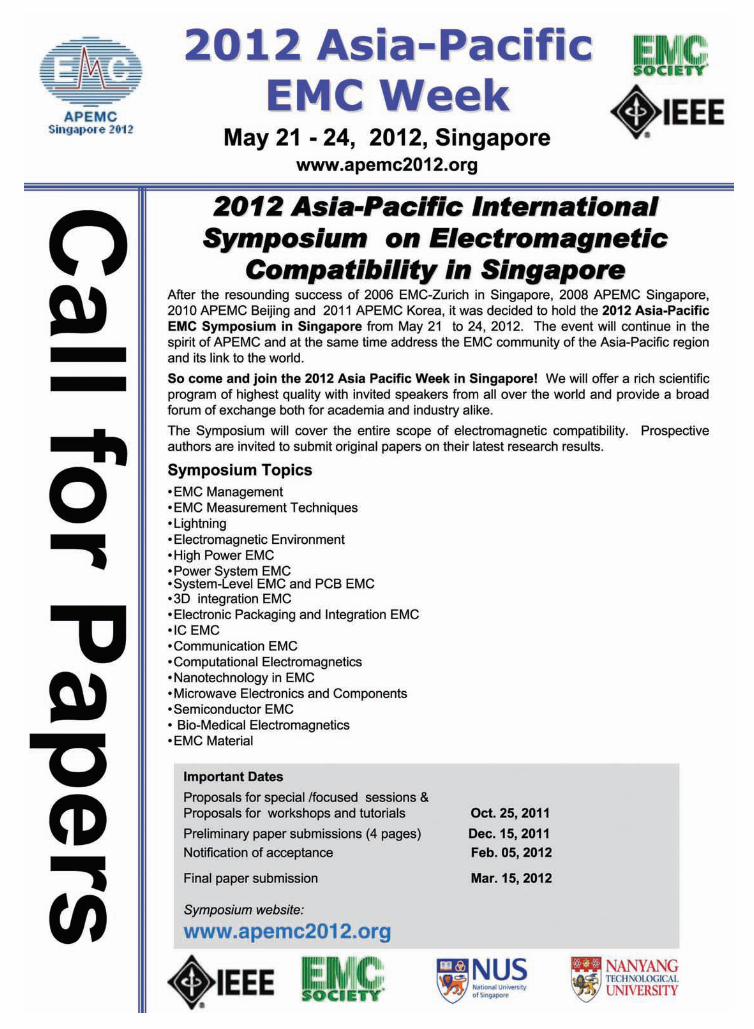
72
Technical Activities of the IEEE, who must then obtain ap-proval of the IEEE Executive Committee. Editorial changes which clarify the meaning, structure or operation of the Board of Directors shall require only the approval of the Board of Di-rectors without notification to the Society membership.
Section 3. The Constitution, Bylaws and Statements of Pol-icy of the IEEE shall, at all times, take precedence over those of the Society.
Amendments to the Bylaws
Section 1: Introduction 1.0 These Bylaws provide guidance for the supervision and management of the IEEE Electromagnetic Compatibility Soci-ety (EMCS), in accordance with the Society Constitution. Amendments may be made by means of the procedures described in Article X, Section 2 of the Constitution.
Suitable amendments may be adopted by a two-thirds vote of the Board of Directors in a meeting assembled, provided that notice of the proposed amendment has been sent to each mem-ber of the Board of Directors at least 15 days prior to such meet-ing; or an amendment may be adopted by a two-thirds mail or email vote by members of the Board of Directors, provided a 30-day period is provided for such responses. In either event, the amendment shall be published in the Society Newsletter or appropriate publication. No amendment shall take effect until it has been published and mailed or emailed to the Managing Director, Technical Activities of the IEEE, along with approval of the General Manager of the IEEE. Editorial changes which clarify the meaning, structure or operation of the Board of Directors shall require only the approval of the Board of Direc-tors without notification to the Society membership.
Section 3: Board of Directors 3.0 Board of Directors: The Board of Directors shall consist of Directors-at-Large and Executive Directors with vote plus elected and appointed Ex-officio Directors without vote. Over fifty percent of the voting members shall constitute a quorum. All voting members shall have an equal vote.
3.1 Directors-at-Large: There shall be at least 18 Directors-at-Large elected by the Society membership. Their term of of-fice shall be three years with 6 Directors-at-Large elected each year. In case of a tie for the sixth and last Director-at-Large slot, or a tie between two candidates from the same qualify-ing region (7, 8, 9, or 10), the Board of Directors shall select the winner(s) by closed (paper) ballot. In addition to the six nominees receiving the largest number of votes, the next top nominees, from IEEE Regions 7, 8, 9, and 10 shall be elected to the Board if the Region is not represented on the Board as a result of the election of the top six nominees or by a carry-over Director- at- Large. To qualify, the Region must have at least 5% of the membership of the Society on December 31 of the year preceding the election and at least 2 nominees from that Region. No Director-at-Large can serve for more than 6 consecutive years. Partial terms, should a Director-at-Large be appointed to fill this position, will apply toward the entire original term of office.
Section 4: Nomination and Election of the Board of Directors4.6 On or before 15 August, IEEE Headquarters will mail and/or email ballots to Society members, with the request that the ballots be returned to IEEE Headquarters by 1 October. The official ballot and cover letter of the final nominations package shall advise voters to “VOTE FOR NO MORE THAN SIX” candidates from the approved slate of nominees. EMC

73
The Secretary’s PavaneBy Kimball Williams, Past President of the IEEE EMC Society
Definition of “Pavane” - A measured, stately dance in which all steps are known to all the participants.
The Secretary in a professional organization such as an IEEE Chapter, Section or Society acts as the ‘spark plug’ for the ‘en-gine’ that we think of as the Executive Committee (ExCom). By maintaining an awareness of critical event timing and functions and ensuring that the necessary ‘spark’ is sent to the relevant of-ficers to initiate preparation and follow up action as needed, the Secretary keeps the entire organization functioning smoothly. In its final form, a well functioning Chapter responding to the Secretary’s prompting behaves like a well choreographed dance troop.
The cycle of meeting activity for a typical Chapter shown below will illustrate this:
Chapter/Section Administrative Teleconferences/Meetings:Meeting date – 14 days: Send draft agenda to Chair for
comment and revision.Meeting date – 12 days: Send revised agenda and last min-
utes to Chapter Officers.Meeting date – 10 days: Send calendar notice of meeting
to Chapter Officers. Meeting date – 7 days: Send e-mail meeting notice to
Chapter Officers.Meeting date – 2 days: Send e-mail reminder of meeting
to Chapter Officers.Meeting date: ----------- Transcribe minutes of the meeting.Meeting date: ----------- Record attendance at meeting.Meeting date + 1 day: Send draft minutes to Chair for
review and comment.Meeting date + 2 day: File V-Tools: L-31 form for IEEE
HQ.Meeting date + 5 days: Send revised draft minutes to
Chapter Officers. Meeting date + 7 days: Update next agenda based on
revised draft minutes.Meeting date + 10 days: Setup V-Tools calendar meeting
page for next meeting.
Of course, as with any dance, all partners in the dance must respond in the proper sequence and at the proper time. As above, for example, the Secretary is dependent on the response from the Chair to the draft agenda sent for comment. If nothing comes back, the rhythm is broken, and the dance falters. In any volunteer organization, time commitments are at the discretion of the volunteer, and it may not always be possible to respond fully, immediately, when the initiative is handed off.
In cases where circumstances force a change in the ‘steps’, it becomes critical to communicate this to the dance partner. A quick e-mail or phone message that confirms:
• I received your document (message/ request/ missive) and • Should be able to reply by (date and time as appropriate) is
vital. The first part lets the partner know that the first message suc-cessfully got through. This puts them at ease. At least they won’t be wondering if it got lost in cyberspace. The second part allows them to alter their normal ‘dance’ pattern to adjust to changing circumstances.
A similar, though shorter dance occurs between the Chapter Secretary and the Section Secretary as they near the time for the monthly Section ExCom meeting:
Section ExCom Meetings:Meeting date – 10 days: Compose Chapter Report for the
Section ExCom.Meeting date – 9 days: Send Chapter Report to the
Chapter Chair for Review.Meeting date – 5 days: Send revised Chapter Report to
Section Secretary.Meeting date: Ensure Chapter is represented at
Section ExCom Meeting.Meeting date + 5 days: Distribute draft ExCom minutes
to Chapter Officers.
As the reports arrive from the Chapter Secretaries, each one should receive an acknowledgement to confirm receipt of the document. Without that, what is the sender to believe? It got lost? It made it through? It was illegible? It got scrambled? It did not make sense?
Also, the rapid turn around of the meeting minutes to the Chapter Secretaries is vital to ensure that actions at the Section level are communicated back to the Chapters as rapidly as pos-sible. This is especially critical when there is a sudden change in a well publicized Section event, or some vital change in operat-ing methods or policy takes place.
Finally a response from the Chapter Secretary to the Section Secretary that they received the copy of the last minutes helps the Section Secretary relax and know that their final twirl in the ‘dance’ was successfully completed.
Occasionally, some parts of the dance are performed almost ‘Solo’. Preparation for a normal monthly membership meeting is a typical example:
Chapter Membership Presentation Meetings:Meeting date – 90 days: Confirm speaker with Bio,
Abstract and Photo.Meeting date – 75 days: Confirm Meeting Venue with
support elements.Meeting date – 60 days: Prepare web ‘Meeting Poster’ for
this event.

74
Meeting date – 45 days: Setup V-Tools calendar meeting page.
Meeting date – 30 days: Send e-mail notice to members (V-Tools link).
Meeting date – 14 days: Send e-mail reminder to members.Meeting date – 5 days: Send e-mail reminder of members.Meeting date: Print list of registered attendees
for “Sign in Sheet”. Meeting date: Attend meeting and help with
last minute ‘issues’. Meeting date + 1 day: Send “Thank You” e-mail to
speaker.Meeting date + 2 day: Fill in V-Tools: L-31 form for
IEEE HQ.Meeting date + 7 days: Send out survey forms to attend-
ees for DL talk.Meeting date + 10 days: Compose meeting article for
newsletter.
As you can see, planning ahead is one of the elements that ensure that the dance is well performed, and that no one missed a step.
Chapter Calendar:One of the most powerful tools in the secretary’s kit is the long range planning calendar. This calendar needs to look at least one year ahead of the current date at all times. The Secretary should be planning activities for the Chapter along with the other relevant Officers at least one year ahead of the current date.
There are a number of advantages to taking this long range view: • Regular meeting dates can be planned well in advance, and
venues, menus, support functions (A/V, Computer, Projector, Microphones, etc.) can be anticipated and scheduled.
• By establishing regular meeting days, times and locations, members (and Officers) become used to the routine, and begin to bend their other schedules around the planned meetings.
• Different types of meetings may be noted (administrative, presentation, tours of plants, workshops, classes, PAC’s, etc.)
• The schedule can be interleaved with other related events of note: Section and Society Conferences, Section ExCom meet-ings, Society Symposia, Sister Chapter events of interest to your membership, etc.
Section V-Tools Calendar:The Section / Chapter V-Tools Calendar becomes an extension of the Chapter’s long range planning calendar, and is one of the communications tools needed to keep members updated on Chapter activity planning. Conversely, the “Register for Meet-ing” feature of the V-Tools calendar provides feed back from Chapter members as to how many are planning to attend a particular meeting.
Meeting date – 45 days: Setup V-Tools calendar meeting page.
Meeting date – 30 days: Send e-mail notice to members (include V-Tools link).
Meeting date – 1 day: Check the number of people regis-tered and advise on refreshments.
Meeting date + 2 day: Fill in V-Tools L-31 form to regis-ter meeting.
Chapter Web Site:The Chapter web site falls into the Secretary’s area of responsi-bility. If you do not possess the skills to actively manipulate the Chapter web site, send your update requests through the Sec-tion Website director for action.
1/Week: Review web site for currency. 1/Month: Review web site for next meeting accuracy. 1/Qtr: Update long range plans. 1/Yr: Include update as a discussion topic for
meeting agenda.
Chapter On-Line Community:The Chapter On-Line Community, if one exists, also falls into the Secretary’s area of responsibility. Ideally, the Secretary should also be one of the administrators for the On-Line Community.
As Occurs: Accept or Reject new member requests.1/Week: Review site for currency. 1/Month: Update site with next meeting agenda and
past meeting minutes. 1/Qtr: Review content of entire site. 1/Yr: Include update as a discussion topic for
meeting agenda.
Of course, all this activity requires a good tool box, well stocked with the appropriate tool for each task. With these tools, the individual jobs become only a matter of knowing when to throw which switch, and how far to turn each valve.
Tools:1) ExCom Meeting agenda template. 2) Macro to facilitate taking minutes directly using the current
agenda. 3) ExCom Meeting notice template. 4) Section “V-Tools” for calendar meeting updates. 5) Chapter ExCom attendance spreadsheet. 6) Chapter Speakers Planning Spreadsheet.7) Link to IEEE HQ (L31 Form) through the “V-Tools” on the
web. 8) Section Chapter monthly Report Format (summarize min-
utes). 9) Blank Roster of the Chapter Executive Committee. 10) E-mail contact list for the Chapter membership (SAMIEEE).
With the tools above, a solid long range plan in place, and cooperative fellow Officers, an active Chapter keeps a Secretary busy, but not frantic. The ‘dance’ is indeed ‘measured’ and, to some degree, ‘stately’, and with all the ‘partners’ dancing in time, it can be a pleasure to watch. EMC
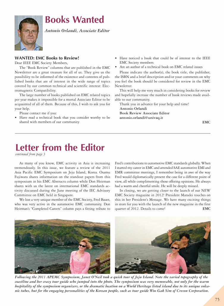
75
Books WantedAntonio Orlandi, Associate Editor
As many of you know, EMC activity in Asia is increasing tremendously. In this issue, we feature a review of the 2011 Asia Pacific EMC Symposium on Jeju Island, Korea. Osamu Fujiwara shares information on the standout papers from this symposium in his EMC Abstracts column while Don Heirman shares with us the latest on international EMC standards ac-tivity discussed during the June meeting of the IEC Advisory Committee on EMC held in Singapore.
We lost a very unique member of the EMC Society, Fred Bauer, who was very active in the automotive EMC community. Don Heirman’s “Completed Careers” column pays a fitting tribute to
Fred’s contributions to automotive EMC standards globally. When I started my career in EMC and attended SAE automotive EMI and EMR committee meetings, I remember being in awe of the way Fred would diplomatically present the case for a different point of view, all while complimenting those offering opinions. He always had a warm and cheerful smile. He will be deeply missed.
In closing, we are getting closer to the launch of our NEW EMC Society magazine in 2012! President Maradei touches on this in her President’s Message. We have many exciting things in store for you with the launch of the new magazine in the first quarter of 2012. Details to come! EMC
WANTED: EMC Books to Review!Dear IEEE EMC Society Members,
The “Book Review” columns that are published in the EMC Newsletter are a great treasure for all of us. They give us the possibility to be informed of the existence and contents of pub-lished books that are of interest in the wide range of topics covered by our common technical and scientific interest: Elec-tromagnetic Compatibility.
The large number of books published on EMC related topics per year makes it impossible for a mortal Associate Editor to be acquainted of all of them. Because of this, I wish to ask you for your help.
Please contact me if you: • Have read a technical book that you consider worthy to be
shared with members of our community
• Have noticed a book that could be of interest to the IEEE EMC Society members
• Are an author of a technical book on EMC related issuesPlease indicate the author(s), the book title, the publisher,
the ISBN and a brief description and/or your comments on why you feel the book should be considered for review in the EMC Newsletter.
This will help me very much in considering books for review and hopefully increase the number of book reviews made avail-able to our community.
Thank you in advance for your help and time!Antonio OrlandiBook Review Associate [email protected]
EMC
Following the 2011 APEMC Symposium, Janet O’Neil took a quick tour of Jeju Island. Note the varied topography of the coastline and her crazy tour guide who jumped into the photo. The symposium was very memorable, not only for the warm hospitality of the symposium organizers, or the dramatic location on a World Heritage listed island due to its unique volca-nic tubes, but for the engaging personalities of the Korean people, such as tour guide Woo Gak Sim of Crezon Corporation.
Letter from the Editorcontinued from page 3
76
The International IEEE COMCAS 2011
Mr. Russell EllwangerProf. Richard Gitlin
Prof. Moshe Kam Prof. Magdalena Salazar PalmaDr. Richard Snyder
Please join us for the 3rd Annual IEEE COMCAS 2011.
Important Deadlines:
ShmShmueluel Au AAAA steteerr r Barry Pererlmalman, RogRoger er PolPo lard
Hi l ton Hote l , Te l Av iv, I s rae l , November 7 -9 , 2011
Platinum Patrons
Gold Patrons Media Support
Technical Co-Sponsors
Suported by the IETIsrael Network
Register Now!Steering Committee
Conference Chairman: Shmuel Auster Elta Systems Ltd.IEEE AP/MTT Chapter Chair, Israel
Technical Program Committee Co-Chairmen: Barry S. PerlmanUS Army CERDEC, USAIEEE MTT-S President 2009
Roger Pollard University of Leeds, UK IEEE VP-TAB [email protected]
Publications Chairman: Benjamin EpsteinOpCoast LLC, USA
Global Administration: Charlotte Blair AWR, USA
Awards and Sponsorship: Barry M. Alexia Rockwell Collins, USA
Members-at-Large: Richard (Dick) SparksRichard (Dick) Sparks IEEE MTT Society
Douglas N. ZuckermanTelcordia Technologies, USAIEEE ComSoc President 2008-9
Elya Joffe IEEE PSES President Elected 2011 IEEE EMCS President 2008-9
Exhibition:Oren Hagai Interlligent, Israel
Finance: Ruth RotmanElta Systems Ltd., Israel
Seccrereetariariariariat:aaaa (aa (all inqinqinqnqinn uiuiruiruiri ies)
OrtOrtOrOrtrtra ara LtdLtdLtdLtd..
www.comcas.org
Calendar
77
EMC Related Conferences & Symposia
2011
November 1–4APL 20117th Asia-Pacific International Conference on Lightning Chengdu, Chinawww.apl2011.org(See ad page 57)
November 6–9EMC Compo 20118th International Workshop on ElectromagneticCompatibility of Integrated Circuits: “EMC-AwareDesign from IC to System Level”Center for Advanced Academic StudiesDubrovnik, Croatia www.emccompo2011.org(See ad page 19)
November 7–9COMCAS 2011 —The International IEEE Conference on Microwaves, Communications, Antennas and Electronic SystemsHilton HotelTel Aviv, Israelwww.comcas.org(See ad page 76)
November 9–11The 10th EMC Society of Australia SymposiumBentley Technology Park Function CentrePerth, AustraliaFranz SchlagenhauferPhone +61 8 9266 9473Email: [email protected](See ad page 60)
2012
May 13–16SPI 201216th IEEE Workshop on Signal Propagation on Interconnections Sorrento, ItalyAntonio MaffucciEmail: [email protected]
May 21–24Asia Pacific EMC Symposium Singaporewww.apemc2012.org(See ad page 71)
May 21–232012 ESA Workshop on Aerospace EMCVenice, ItalyFilippo Marlianiwww.hirf-se.eu
July 2–6EUROEM 2012 European Conference and Exhibition on ElectromagneticsToulouse, FranceJean-Philippe Parmantierwww.euroem.org
September 17–21EMC Europe 2012Rome, Italywww.emceurope2012.it(See ad page 31)
November 6–9CEEM 20126th Asia-Pacific Conference onEnvironmental Electromagnetics Shanghai, ChinaProf. Gao Yougangwww.emc2012beijing.com
EMC Annual Symposia Schedule
2012 August 6–10 Pittsburgh, Pennsylvania Mike Oliver, 814.763.3211 (See ad
pages 32–33)
2013 August 5–9 Denver, Colorado Danny Odum, 303.693.1778
2014 August 3–7 Raleigh, North Carolina Bruce Archambeault, 919.486.0120
2015 August 16–22 Dresden, Germany Hans Georg Krauthäuser, +49 (0)351.463.33357 [email protected]
2016 July 25–29 Ottawa, Canada Qiubo Ye, 613.998.2769
IEEE EMC Board of Directors and Standards Committee MeetingsPlease note the Standards committee meetings of the IEEE EMC Society are held in conjunction with the EMC Board meetings listed below. All Standards committee meetings are open to anyone with an interest in EMC standards. To attend a Standards committee meeting at one of the locations below, contact Don Heirman at [email protected]. Board meetings are also open to those interested in the administration of the EMC Society. For information on the Board meetings, contact Janet O’Neil, 425.868.2558, [email protected]. Your involvement is welcome!
November 15–17, 2011 IEEE HeadquartersPiscataway, New Jersey
March 16–18, 2012Scottsdale, Arizona
August 5 and 9, 2012Pittsburgh, Pennsylvania
November 16–18, 2012Raleigh, North Carolina
EMC Chapter Colloquium and Exhibition “Table-Top Shows”
2011October 26 Seattle, Washington Mark Steffka, EMC-S Distinguished Lecturer John Norgard, NASA-Houston Museum of Flight Janet O’Neil, ETS-Lindgren Phone: 425.868.2558 Email: [email protected]
2012March 27Milwaukee, WisconsinJeremy Campbell, PEGeneral Motors, Applied Technology CenterTopic to be announcedCrown Plaza Hotel – Milwaukee Airport Jim Blaha, GE HealthcarePhone: 262.548.2978Email: [email protected]
May 9Chicago, IllinoisSpeaker and topic to be announcedItasca Country Club Itasca, IllinoisFrank Krozel, Electronic InstrumentsPhone: 630.924.1600Email: [email protected]
May 16Detroit, MichiganSpeaker and topic to be announcedCanton Summit on the ParkScott Lytle, Yazaki North AmericaPhone: 734.983.6012Email: [email protected]
If you would like to add your name to the list of exhibitors to receive direct announcements in advance of these upcoming tabletop shows, please send an e-mail to [email protected]
78
ADVERTISER’S INDEX
The Advertiser’s Index contained in this issue is compiled as a service to our readers and advertisers. The publisher is not liable for errors or omissions although every effort is made to ensure its accuracy. Be sure to let our advertisers know you found them through the IEEE EMC Newsletter.
Advertiser’s Index Page #
A.H. SYSTEMS . . . . . . . . . . . . . . . Back Cover
www.AHSystems.com
Agilent Technologies . . . . . . . . . . . . . . . . . . 21
www.agilent.com/find/AgilentEMIreceiver
AR RF/Microwave Instrumentation . . . . . .5
www.ar-worldwide.com
CST-America . . . . . . . . . . . Inside Front Cover
www.cst.com
EM Software & Systems . . . . . . . . . . . . . . . . .7
www.feko.info
EMCCons . . . . . . . . . . . . . . . . . . . . . . . . . . . . 11
www.emcc.de
EMCCons . . . . . . . . . . . . . . . . . . . . . . . . . . . . 13
www.emcc.de
EMCCons . . . . . . . . . . . . . . . . . . . . . . . . . . . . 15
www.emcc.de
IEEE Marketing
Department . . . . . . . . . . . . .Inside Back Cover
www.ieee.org/livehealthier
Lehman Chambers . . . . . . . . . . . . . . . . . . . . 23
www.CumingLehman.com
Quell Corporation . . . . . . . . . . . . . . . . . . . . .29
www.eeseal.com
Spira Manufacturing . . . . . . . . . . . . . . . . . . 25
www.spira-emi.com
MANAGEMENTJames A. VickStaff Director, AdvertisingPhone: 212-419-7767 Fax: [email protected]
Susan E. SchneidermanBusiness Development ManagerPhone: 732-562-3946Fax: [email protected]
Marion DelaneyAdvertising Sales DirectorPhone: 415-863-4717Fax: [email protected]
PRODUCT ADVERTISINGMidatlanticLisa Rinaldo Phone: 732-772-0160 Fax: [email protected], NJ, PA, DE, MD, DC, KY, WV
New England/South Central/ Eastern Canada Jody EstabrookPhone: 774-283-4528Fax: [email protected], VT, NH, MA, RI, CT,AR, LA, OK, TXCanada: Quebec, Nova Scotia, Newfoundland, Prince Edward Island, New Brunswick
SoutheastThomas FlynnPhone: 770-645-2944 Fax: [email protected], NC, SC, TN, AL, GA, MS, FL
Midwest/Central Canada Dave JonesPhone: 708-442-5633Fax: [email protected] IL, IA, KS, MN, MO, NE, ND, SD, WICanada: Manitoba, Saskatchewan, Alberta
Midwest/Ontario, CanadaWill HamiltonPhone: 269-381-2156Fax: [email protected], MI. Canada: Ontario
West Coast/Mountain States/ Western CanadaMarshall RubinPhone: 818-888-2407Fax: 818-888-4907 [email protected], CO, HI, NM, NV, UT, AK, ID, MT, WY, OR, WA, CA. Canada: British Columbia
Europe/Africa/Middle EastHeleen VodegelPhone: 44 –187-582-5700Fax: 44 –187-582-5701 [email protected], Africa, Middle East
Asia/Far East/ Pacific Rim Susan Schneiderman Phone: 732-562-3946Fax: 732-981-1855 [email protected], Far East, Pacific Rim, Australia, New Zealand
RECRUITMENT ADVERTISINGMidatlanticLisa RinaldoPhone: 732-772-0160Fax: [email protected], NJ, CT, PA, DE, MD, DC, KY, WV
New England/ Eastern CanadaLiza ReichPhone: 212-419-7578Fax: [email protected], VT, NH, MA, RICanada: Nova Scotia, Prince Edward Island, Newfoundland, New Brunswick, Quebec
SoutheastCathy FlynnPhone: 770-645-2944Fax: [email protected], NC, SC, GA, FL, AL, MS, TN
Midwest/South Central/ Central CanadaDarcy GiovingoPhone: 847-498-4520Fax: [email protected]; AR, IL, IN, IA, KS, LA, MI, MN, MO, NE, ND, SD, OH, OK, TX, WI. Canada: Ontario, Manitoba, Saskatchewan, Alberta
West Coast/Southwest/ Mountain States/AsiaTim MattesonPhone: 310-836-4064Fax: [email protected], CO, HI, NV, NM, UT, CA, AK, ID, MT, WY, OR, WA. Canada: British Columbia
Europe/Africa/Middle EastHeleen VodegelPhone: 44 –187-582-5700Fax: 44 –[email protected] Europe, Africa, Middle East
IEEE EMC Society Newsletter Advertising Sales Offices445 Hoes Lane, Piscataway NJ 08854
www.ieee.org/ieeemediaImpact this hard-to-reach audience in their own Society publication.
For further information on product and recruitment advertising, call your local sales office.

Can new telemedicine standards keep us healthier longer?
IEEE Xplore® Digital LibraryInformation driving innovation
Try IEEE Xplore free—
visit www.ieee.org/livehealthier
Find the latest research in IEEE Xplore
Wherever you fi nd people developing the most advanced
technology, chances are you’ll fi nd them using the IEEE
Xplore digital library. That’s because IEEE Xplore is fi lled with
the latest research on everything from wireless technology
and solid-state circuits—to telemedicine standards that can
help us get more out of life.
When it comes to technology, the research that matters is
in IEEE Xplore.
See for yourself. Read “Evaluation of Security and Privacy
Issues in Integrated Mobile Telemedical System,” only in
IEEE Xplore.
Related Documents