Exploration of distributed propeller regional aircraft design Baizura Bohari 1,2 , Emmanuel Benard 1 , Murat Bronz 2 1 University of Toulouse - ISAE Supaero, Dept. of Aeronautic and Space Vehicles Design (DCAS) 2 University of Toulouse - ENAC, UAV Laboratory F-31055 10 juillet 2018 Baizura Bohari (ISAE/ENAC) 5th Drone Garden Workshop 2018 10 juillet 2018 1 / 43

Welcome message from author
This document is posted to help you gain knowledge. Please leave a comment to let me know what you think about it! Share it to your friends and learn new things together.
Transcript
Exploration of distributed propeller regional aircraft design
Baizura Bohari1,2, Emmanuel Benard1, Murat Bronz2
1University of Toulouse - ISAE Supaero, Dept. of Aeronautic andSpace Vehicles Design (DCAS)
2University of Toulouse - ENAC, UAV Laboratory F-31055
10 juillet 2018
Baizura Bohari (ISAE/ENAC) 5th Drone Garden Workshop 2018 10 juillet 2018 1 / 43

Outline
1 IntroductionThe big picture
2 Multidisciplinary Design Analysis (MDA)General frameworkFixed-wing Aircraft Sizing Tool - FAST
3 Aerodynamic ModuleModeling Frameworks
4 Verification and Synthesis ResultsValidation - Aerodynamic modelPropeller-Wing Interaction -LinearPropeller-Wing Interaction - Non-linear with high lift deviceValidation - FAST
5 Conclusions and Future WorksConclusionsFuture Works
6 References
Baizura Bohari (ISAE/ENAC) 5th Drone Garden Workshop 2018 10 juillet 2018 2 / 43
Plan
1 Introduction
2 Multidisciplinary Design Analysis (MDA)
3 Aerodynamic Module
4 Verification and Synthesis Results
5 Conclusions and Future Works
6 References
Baizura Bohari (ISAE/ENAC) 5th Drone Garden Workshop 2018 10 juillet 2018 3 / 43

Plan
1 IntroductionThe big picture
Baizura Bohari (ISAE/ENAC) 5th Drone Garden Workshop 2018 10 juillet 2018 4 / 43

Distributed Propellers Aircraft Concept
FIGURE 1 – ESAero NASA X-57 Maxwell [2] 1FIGURE 2 – Vahana, the self-piloted, EVTOLAircraft from A3 by Airbus. 2
Features :- Multiple propellers distributed along the
wing span
- OEI condition less stringent
- Wing area reduced/Shorter Takeoff FieldLength
- High CL,max
Issues : Unconventional configuration- No semi-empirical formula
- Need cheap prediction tools ) low fidelity
1. NASA Illustration, Scalable Convergent Electric Propulsion Technology Operations Research (SCEPTOR) project,https://www.nasa.gov/centers/armstrong/features/CAS_showcase.html, Feb 2017
2. Vahana, the self-piloted, EVTOL Aircraft from A3 by Airbus, https://www.airbus.com, Jun 2018
Baizura Bohari (ISAE/ENAC) 5th Drone Garden Workshop 2018 10 juillet 2018 5 / 43

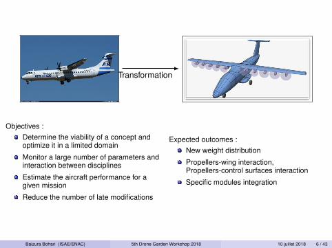
Transformation
Objectives :Determine the viability of a concept andoptimize it in a limited domainMonitor a large number of parameters andinteraction between disciplines
Estimate the aircraft performance for agiven mission
Reduce the number of late modifications
Expected outcomes :New weight distribution
Propellers-wing interaction,Propellers-control surfaces interaction
Specific modules integration
Baizura Bohari (ISAE/ENAC) 5th Drone Garden Workshop 2018 10 juillet 2018 6 / 43

Transformation
Objectives :Determine the viability of a concept andoptimize it in a limited domain
Monitor a large number of parameters andinteraction between disciplines
Estimate the aircraft performance for agiven mission
Reduce the number of late modifications
Expected outcomes :New weight distribution
Propellers-wing interaction,Propellers-control surfaces interaction
Specific modules integration
Baizura Bohari (ISAE/ENAC) 5th Drone Garden Workshop 2018 10 juillet 2018 6 / 43

Plan
1 Introduction
2 Multidisciplinary Design Analysis (MDA)
3 Aerodynamic Module
4 Verification and Synthesis Results
5 Conclusions and Future Works
6 References
Baizura Bohari (ISAE/ENAC) 5th Drone Garden Workshop 2018 10 juillet 2018 7 / 43
Plan
2 Multidisciplinary Design Analysis (MDA)General frameworkFixed-wing Aircraft Sizing Tool - FAST
Baizura Bohari (ISAE/ENAC) 5th Drone Garden Workshop 2018 10 juillet 2018 8 / 43

Framework
General multidisciplinary analysis framework[3] 3
AircraftDesign
Variables
Missionrequirements
0, 5!1:MDO:
Optimization
1:Fuel weight
t
SFC
t
2:Total weight
t
Load
t
3:Lift
t
Drag
t
Optimizedpropulsioncoe↵cients
5:SFC
1:Propulsionsystem
sizing andintegration
2:Propulsionmass/weight
3:Propulsion
powerand thrustcoe�cients
4:SFC
Optimizedmass/weightparameters
5:Total and fuel
weight
2:Mass/weight
analysis
3:Displacements
4:Total weightFuel weight
Optimizedaerodynamiccoe�cients
5:Lift and Drag
Load
3:Low,
Medium,Highfidelityanalysis
4:LiftDrag
Finaloperating
costs
4:MissionAnalysis
FIGURE 3 – Multidisciplinary design analysis workflow.
3. A.B. Lambe et al., Extensions to the Design Structure Matrix for the Description of Multidiplinary Design, Analysis, and Optimization Processes,Structural and Multidisciplinary Optimization, 2012
Baizura Bohari (ISAE/ENAC) 5th Drone Garden Workshop 2018 10 juillet 2018 9 / 43

Plan
2 Multidisciplinary Design Analysis (MDA)General frameworkFixed-wing Aircraft Sizing Tool - FAST
Baizura Bohari (ISAE/ENAC) 5th Drone Garden Workshop 2018 10 juillet 2018 10 / 43

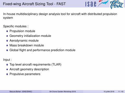
Fixed-wing Aircraft Sizing Tool - FAST
In-house multidisciplinary design analysis tool for aircraft with distributed propulsionsystem
Specific modules :Propulsion moduleGeometry initialization moduleAerodynamic moduleMass breakdown moduleGlobal flight and performance prediction module
Input :Top level aircraft requirements (TLAR)Aircraft geometry descriptionPropulsive parameters
Output :Mission profilesAircraft geometry sizingAerodynamic components’characteristicsWeight and balance
Baizura Bohari (ISAE/ENAC) 5th Drone Garden Workshop 2018 10 juillet 2018 11 / 43

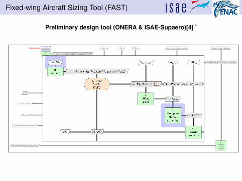
Fixed-wing Aircraft Sizing Tool (FAST)
Preliminary design tool (ONERA & ISAE-Supaero)[4] 4
Initial input
Wing sizing
Geometry
Aerodynamics and Weight estimation
Performance evaluation
xmlfile Vapproach
Npax
SMreq
Req. range, Cruise option Range, Mach, Altitude
0:Initiator 1 : PL(0), MTOW (0), MLW (0), MZFW (0), S
(0)w
1, 9æ2:MDA:FAST
2 : mt
f
, MLW t, Ct
L
max
3 : MTOW t 4 : Massest 9 : Massest, A/Ct, CL
(CD
)t, CL
(–)t
2:Wingsizing
3 : ywing
3:Compute
initialgeometry
4 : A/C(0)
A/C 9 : A/C4:
Resizegeometry
5 : A/C 6 : A/C
CL
(CD
), CL
(–) 9 : CL
(CD
), CL
(–)5:
Computeaerody-namics
7 : CL
(CD
), CL
(–)
Masses 9 : Masses
6:Massbreak-down
7 : Masses 8 : OWE
Sizing mission performances 9 : mf
7:Globalflight
8 : mf
, OWEm
9 : MTOW8:
UpdateMTOW
Operational mission performances9:
Opera-tional
mission
4. P. Schmollgruber et al., Use of a Certification Constraints Module for Aircraft Design Activities, AIAA Aviation Meeting, 2017
Baizura Bohari (ISAE/ENAC) 5th Drone Garden Workshop 2018 10 juillet 2018 12 / 43
Plan
1 Introduction
2 Multidisciplinary Design Analysis (MDA)
3 Aerodynamic Module
4 Verification and Synthesis Results
5 Conclusions and Future Works
6 References
Baizura Bohari (ISAE/ENAC) 5th Drone Garden Workshop 2018 10 juillet 2018 13 / 43
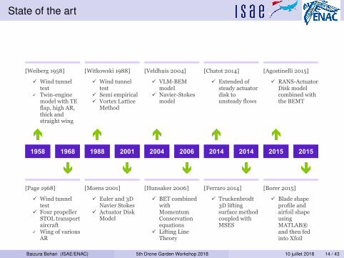
State of the art
[Weiberg 1958]
! Wind tunnel test
! Twin-engine model with TE flap, high AR, thick and straight wing
[Witkowski 1988]
! Wind tunnel test
! Semi empirical ! Vortex Lattice
Method
[Veldhuis 2004]
! VLM-BEM model
! Navier-Stokes model
[Chatot 2014]
! Extended of steady actuator disk to unsteady flows
[Agostinelli 2015]
! RANS-Actuator Disk model combined with the BEMT
1958 1968
1988 2001
2004 2006
2014 2014
2015 2015
[Page 1968]
! Wind tunnel test
! Four propeller STOL transport aircraft
! Wing of various AR
[Moens 2001]
! Euler and 3D Navier Stokes
! Actuator Disk Model
[Hunsaker 2006]
! BET combined with Momentum Conservation equations
! Lifting Line Theory
[Ferraro 2014]
! Truckenbrodt 3D lifting surface method coupled with MSES
[Borer 2015]
! Blade shape profile and airfoil shape using MATLAB® and then fed into Xfoil
! Post-processing results with XROTOR
FIGURE 4 –
Baizura Bohari (ISAE/ENAC) 5th Drone Garden Workshop 2018 10 juillet 2018 14 / 43

Plan
3 Aerodynamic ModuleModeling Frameworks
Baizura Bohari (ISAE/ENAC) 5th Drone Garden Workshop 2018 10 juillet 2018 15 / 43
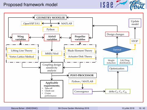
Proposed framework model
Op#mal
Update model
Wing variables
Propeller variables
Coupling design sensitivity analysis
STOP
POST-PROCESSOR
OpenVSP 3.9.1
Weight reduction
Lift/Drag distribution
Airfoil variables
MSES/Xfoil
Applicable requirements;
• Take-off • Climb-out • Cruise
performance
Convergence delta CP, CL, CDi
Python / MATLAB
Optimization
Design changes
Blade Element Theory
Actuator Disk Theory Vortex Lattice Method
Lifting Line Theory
GEOMETRY MODELER
MATLAB
Python
Baizura Bohari (ISAE/ENAC) 5th Drone Garden Workshop 2018 10 juillet 2018 16 / 43

Proposed framework model
FIGURE 5 – Workflow of aerodynamic module (linear)
Baizura Bohari (ISAE/ENAC) 5th Drone Garden Workshop 2018 10 juillet 2018 17 / 43
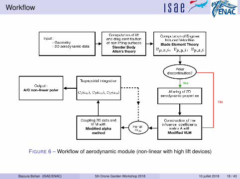
Workflow
FIGURE 6 – Workflow of aerodynamic module (non-linear with high lift devices)
Baizura Bohari (ISAE/ENAC) 5th Drone Garden Workshop 2018 10 juillet 2018 18 / 43

Propellers induced velocity
Propellers induced velocity :Uniform blade loadingFroude and Blade Element Theory
FIGURE 7 – Example of propellers induced velocities with the BET
Baizura Bohari (ISAE/ENAC) 5th Drone Garden Workshop 2018 10 juillet 2018 19 / 43
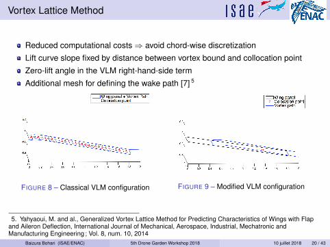
Vortex Lattice Method
Reduced computational costs ) avoid chord-wise discretizationLift curve slope fixed by distance between vortex bound and collocation pointZero-lift angle in the VLM right-hand-side termAdditional mesh for defining the wake path [7] 5
FIGURE 8 – Classical VLM configuration FIGURE 9 – Modified VLM configuration
5. Yahyaoui, M. and al., Generalized Vortex Lattice Method for Predicting Characteristics of Wings with Flapand Aileron Deflection, International Journal of Mechanical, Aerospace, Industrial, Mechatronic andManufacturing Engineering ; Vol. 8, num. 10, 2014
Baizura Bohari (ISAE/ENAC) 5th Drone Garden Workshop 2018 10 juillet 2018 20 / 43

Plan
1 Introduction
2 Multidisciplinary Design Analysis (MDA)
3 Aerodynamic Module
4 Verification and Synthesis Results
5 Conclusions and Future Works
6 References
Baizura Bohari (ISAE/ENAC) 5th Drone Garden Workshop 2018 10 juillet 2018 21 / 43
Plan
4 Verification and Synthesis ResultsValidation - Aerodynamic modelPropeller-Wing Interaction -LinearPropeller-Wing Interaction - Non-linear with high lift deviceValidation - FAST
Baizura Bohari (ISAE/ENAC) 5th Drone Garden Workshop 2018 10 juillet 2018 22 / 43
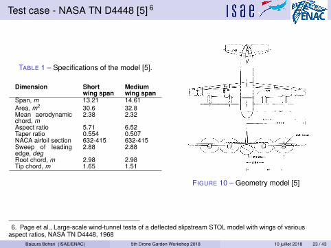
Test case - NASA TN D4448 [5] 6
TABLE 1 – Specifications of the model [5].
Dimension Shortwing span
Mediumwing span
Span, m 13.21 14.61Area, m2 30.6 32.8Mean aerodynamicchord, m
2.38 2.32
Aspect ratio 5.71 6.52Taper ratio 0.554 0.507NACA airfoil section 632-415 632-415Sweep of leadingedge, deg
2.88 2.88
Root chord, m 2.98 2.98Tip chord, m 1.65 1.51
FIGURE 10 – Geometry model [5]
6. Page et al., Large-scale wind-tunnel tests of a deflected slipstream STOL model with wings of variousaspect ratios, NASA TN D4448, 1968
Baizura Bohari (ISAE/ENAC) 5th Drone Garden Workshop 2018 10 juillet 2018 23 / 43
Plan
4 Verification and Synthesis ResultsValidation - Aerodynamic modelPropeller-Wing Interaction -LinearPropeller-Wing Interaction - Non-linear with high lift deviceValidation - FAST
Baizura Bohari (ISAE/ENAC) 5th Drone Garden Workshop 2018 10 juillet 2018 24 / 43

CL � ↵ curves for three different tools
FIGURE 11 – Tc’ = 1.0 FIGURE 12 – Tc’ = 2.4
Baizura Bohari (ISAE/ENAC) 5th Drone Garden Workshop 2018 10 juillet 2018 25 / 43

Lift and drag polars of medium wing span
FIGURE 13 – Tc’ = 3.8 FIGURE 14 – CL � CD curves for 3 Tc’
Baizura Bohari (ISAE/ENAC) 5th Drone Garden Workshop 2018 10 juillet 2018 26 / 43
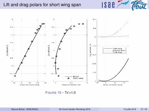
Lift and drag polars for short wing span
FIGURE 15 – Tc’=1.0
Baizura Bohari (ISAE/ENAC) 5th Drone Garden Workshop 2018 10 juillet 2018 27 / 43

Lift and drag polars for short wing span
FIGURE 16 – Tc’=4.9
Baizura Bohari (ISAE/ENAC) 5th Drone Garden Workshop 2018 10 juillet 2018 28 / 43
Plan
4 Verification and Synthesis ResultsValidation - Aerodynamic modelPropeller-Wing Interaction -LinearPropeller-Wing Interaction - Non-linear with high lift deviceValidation - FAST
Baizura Bohari (ISAE/ENAC) 5th Drone Garden Workshop 2018 10 juillet 2018 29 / 43

Aircraft - Smooth configuration - Propellers on
Angle of attack [deg]-10 -5 0 5 10 15 20
Lift
coeffic
ient
-1
-0.5
0
0.5
1
1.5
2
2.5Lift coefficient vs. angle of attack
NumericalExperimental
Drag coefficient0 0.1 0.2 0.3 0.4 0.5 0.6
Lift
coeffic
ient
-1
-0.5
0
0.5
1
1.5
2
2.5Lift coefficient vs. drag coefficient
NumericalExperimental
FIGURE 17 – Full a/c configuration - no flaps - Tc = 0.90 - NACA TN 4365 [6] 7.
Validation of the model for propellers’ induced velocity : ✏%,cl,max = 8%No convergence for steep stall
7. Weiberg and al., Large scale wind-tunnel tests of an airplane model with an unswept, aspect-ratio 10 wing,two propellers and area-suction flaps, NACA TN 4365, 1958
Baizura Bohari (ISAE/ENAC) 5th Drone Garden Workshop 2018 10 juillet 2018 30 / 43

Aircraft - High-lift configuration - Propellers on
Angle of attack [deg]-10 -5 0 5 10 15 20
Lift
coeffic
ient
0
0.5
1
1.5
2
2.5
3
3.5Lift coefficient vs. angle of attack
NumericalExperimental
Drag coefficient0.2 0.3 0.4 0.5 0.6 0.7 0.8 0.9
Lift
coeffic
ient
0
0.5
1
1.5
2
2.5
3
3.5Lift coefficient vs. drag coefficient
NumericalExperimental
FIGURE 18 – Full a/c configuration - flaps 40� - Tc 0.75 - NACA TN 4365 [6] 11.
Lack of accuracy on ↵L,max , but not on cl,max : ✏%,cl,max = 1%
7. Weiberg and al., Large scale wind-tunnel tests of an airplane model with an unswept, aspect-ratio 10 wing,two propellers and area-suction flaps, NACA TN 4365, 1958
Baizura Bohari (ISAE/ENAC) 5th Drone Garden Workshop 2018 10 juillet 2018 31 / 43
Plan
4 Verification and Synthesis ResultsValidation - Aerodynamic modelPropeller-Wing Interaction -LinearPropeller-Wing Interaction - Non-linear with high lift deviceValidation - FAST
Baizura Bohari (ISAE/ENAC) 5th Drone Garden Workshop 2018 10 juillet 2018 32 / 43
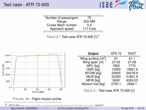
Test case - ATR 72-600
Number of passengers 70Range 825 NM
Cruise Mach number 0.4Approach speed 117.5 kts
TABLE 2 – Test case ATR 72-600 [1] 7
FIGURE 19 – Flight mission profile
Output ATR 72 FASTWing surface [m2] 61 61.1
Wing span [m] 27.05 27.08MPL [kg] 7850 7770OWE [kg] 12950 12801.8
MTOW [kg] 23000 24278.9MLW [kg] 22350 21801.9MFW [kg] 5000 4324.23
Mission fuel [kg] 2750.1 2689.1
TABLE 3 – Test case ATR 72-600 [1]
7. ATR 72-600, www.atr-aircraft.com/datas/download_center/27/fiche72_27.pdf/, Feb 2017Baizura Bohari (ISAE/ENAC) 5th Drone Garden Workshop 2018 10 juillet 2018 33 / 43

Output
FIGURE 20 – Climb profile FIGURE 21 – Descent profile
Baizura Bohari (ISAE/ENAC) 5th Drone Garden Workshop 2018 10 juillet 2018 34 / 43

Plan
1 Introduction
2 Multidisciplinary Design Analysis (MDA)
3 Aerodynamic Module
4 Verification and Synthesis Results
5 Conclusions and Future Works
6 References
Baizura Bohari (ISAE/ENAC) 5th Drone Garden Workshop 2018 10 juillet 2018 35 / 43
Plan
5 Conclusions and Future WorksConclusionsFuture Works
Baizura Bohari (ISAE/ENAC) 5th Drone Garden Workshop 2018 10 juillet 2018 36 / 43

Conclusions
We have seen :Linear prediction of BVLM code in the presence of slipstream isvery well predicted and validatedThe effects of the spanwise variation of propeller thrust onlongitudinal characteristicsNon-linear with high lift device aerodynamic analysis for thepropeller wing interaction with a very minimum computational costsFAST has been validated for regional aircraft with conventionalpropulsive systems (A320 & ATR72-600)Aerodynamic module provides results good in agreement withexperimental measurements for preliminary design stepBoth FAST and aerodynamic module are able to take multiplepropellers along the wing
Limitations of aerodynamic module :High dependency in 2D aerodynamic dataPost-stall convergence if soft stall
Baizura Bohari (ISAE/ENAC) 5th Drone Garden Workshop 2018 10 juillet 2018 37 / 43
Plan
5 Conclusions and Future WorksConclusionsFuture Works
Baizura Bohari (ISAE/ENAC) 5th Drone Garden Workshop 2018 10 juillet 2018 38 / 43

Future Works
In the future :To integrate the updated specific modules, aerodynamic, mass, etc.with FASTTo continue with the MDO process focusing on the optimzation ofthe propeller numbers, location and size along the wing span.To expand the current aircraft model to hybrid electric configuration.
Baizura Bohari (ISAE/ENAC) 5th Drone Garden Workshop 2018 10 juillet 2018 39 / 43

Thank you
- All models are wrong, and the value of any model is only to the extent to which itsupports the purpose for which it was built.- George E. P. Box
Baizura Bohari (ISAE/ENAC) 5th Drone Garden Workshop 2018 10 juillet 2018 40 / 43

Plan
1 Introduction
2 Multidisciplinary Design Analysis (MDA)
3 Aerodynamic Module
4 Verification and Synthesis Results
5 Conclusions and Future Works
6 References
Baizura Bohari (ISAE/ENAC) 5th Drone Garden Workshop 2018 10 juillet 2018 41 / 43
References I
ATR.ATR 72-600.https://www.atr-aircraft.com/datas/download_center/27/
fiche72_27.pdf/.
NASA Illustration.Scalable convergent electric propulsion technology operations research (sceptor)project.https:
//www.nasa.gov/centers/armstrong/features/CAS_showcase.html,Available online since 11/4/15, consulted the 16/12/17.
Lambe, Andrew B. and Martins, Joaquim R. R. A.Extensions to the design structure matrix for the description of multidisciplinarydesign, analysis, and optimization processes.Structural and Multidisciplinary Optimization, 46(2) :273–284, 2012.
A. Sgueglia S. Defoort R. Lafarge N. Bartoli Y. Gourinat P. Schmollgruber,J. Bedouet and E. Benard.Use of Certification Constraints Module for Aircraft Design Activities.In AIAA Aviation Forum, number AIAA 2017-3762, 2017.
Baizura Bohari (ISAE/ENAC) 5th Drone Garden Workshop 2018 10 juillet 2018 42 / 43

References II
V. Robert Page, Stanley O. Dickinson, and Wallace H. Deckert.Large-scale wind-tunnel tests of a deflected slipstream STOL model with wings ofvarious aspect ratios.Technical report, National Aeronautics and Space Administration, Washington, D.C., 1968.
Weiberg James A., Friggin Roy N. Jr.Florman Georges L. .Large scale wind-tunnel tests of anairplane model with an unswept, aspect-ratio10 wing, two propellers and area-suction flaps.NACA Technical Note, 4365, 1958.
M. Yahyaoui.Generalized vortex lattice method for predicting characteristics of wings with flapand aileron deflection.International Journal of Mechanical, Aerospace, Industrial, Mechatronic andManufacturing Engineering, 8(10), 2014.
Baizura Bohari (ISAE/ENAC) 5th Drone Garden Workshop 2018 10 juillet 2018 43 / 43
Related Documents


