Engineer-to-Engineer Note EE-322 Technical notes on using Analog Devices DSPs, processors and development tools Visit our Web resources http://www.analog.com/ee-notes and http://www.analog.com/processors or e-mail [email protected] or [email protected] for technical support. Expert Code Generator for SHARC® Processors Contributed by Mitesh Moonat Rev 5 – January 17, 2012 Copyright 2009-2012, Analog Devices, Inc. All rights reserved. Analog Devices assumes no responsibility for customer product design or the use or application of customers’ products or for any infringements of patents or rights of others which may result from Analog Devices assistance. All trademarks and logos are property of their respective holders. Information furnished by Analog Devices applications and development tools engineers is believed to be accurate and reliable, however no responsibility is assumed by Analog Devices regarding technical accuracy and topicality of the content provided in Analog Devices Engineer-to-Engineer Notes. Introduction The Expert Code Generator (ECG) can be used to generate code for initializing specific SHARC® processor blocks to the system’s requirements. The ADSP-214xx family of SHARC processors includes new modules and enhanced features compared to older SHARC processors. Some important new blocks include the Double Data Rate 2 (DDR2) controller (ADSP-2146x processors only), the Finite Impulse Response (FIR), Infinite Impulse Response (IIR), and Fast Fourier Transform (FFT) hardware accelerators. In addition, the ECG also produces initialization code for the Phase-Locked Loop (PLL), SDRAM, and Asynchronous Memory Interface (AMI) controllers both for new and the older SHARC processors (ADSP-2126x and ADSP-213xx processors). The Expert Code Generator consists of two utilities that can be directly integrated as plug-ins to VisualDSP++® development tools: Code generator for initializing PLL, DDR2/SDRAM, and AMI controllers Code generator for FIR, IIR, and FFT accelerators To generate the code, you enter high-level system parameters without needing to know the processor- specific details. This saves software developers a lot of time and effort. This application note discusses, in detail, how to use these utilities to generate the required code. Expert Code Generator Uses Managing Limitations and Restrictions Automatically Restrictions/limitations may need to be addressed when programming certain modules. One typical example is the maximum Voltage-Controlled Oscillator (VCO) frequency limitation for the PLL. This limitation implies that not all combinations of PLLM and PLLD of the PMCTL register can be used. You should ensure that the VCO frequency does not cross its maximum limit. Expert Code Generator eases the programmer’s task by taking care of these types of restrictions. Translating DDR2/SDRAM Device Specifications Taken Directly from the Device Data Sheet to the Code Initializing the DDR2/SDRAM controller for a particular DDR2/SDRAM device requires a number of control registers to be configured. Each timing specification needs to be programmed in terms of DDR2CLK/SDCLK cycles. Converting these timing specifications in terms of DDR2CLK/SDCLK cycles

Welcome message from author
This document is posted to help you gain knowledge. Please leave a comment to let me know what you think about it! Share it to your friends and learn new things together.
Transcript
Engineer-to-Engineer Note EE-322
Technical notes on using Analog Devices DSPs, processors and development tools Visit our Web resources http://www.analog.com/ee-notes and http://www.analog.com/processors or e-mail [email protected] or [email protected] for technical support.
Expert Code Generator for SHARC® Processors Contributed by Mitesh Moonat Rev 5 – January 17, 2012
Copyright 2009-2012, Analog Devices, Inc. All rights reserved. Analog Devices assumes no responsibility for customer product design or the use or application of customers’ products or for any infringements of patents or rights of others which may result from Analog Devices assistance. All trademarks and logos are property of their respective holders. Information furnished by Analog Devices applications and development tools engineers is believed to be accurate and reliable, however no responsibility is assumed by Analog Devices regarding technical accuracy and topicality of the content provided in Analog Devices Engineer-to-Engineer Notes.
Introduction The Expert Code Generator (ECG) can be used to generate code for initializing specific SHARC® processor blocks to the system’s requirements. The ADSP-214xx family of SHARC processors includes new modules and enhanced features compared to older SHARC processors. Some important new blocks include the Double Data Rate 2 (DDR2) controller (ADSP-2146x processors only), the Finite Impulse Response (FIR), Infinite Impulse Response (IIR), and Fast Fourier Transform (FFT) hardware accelerators. In addition, the ECG also produces initialization code for the Phase-Locked Loop (PLL), SDRAM, and Asynchronous Memory Interface (AMI) controllers both for new and the older SHARC processors (ADSP-2126x and ADSP-213xx processors). The Expert Code Generator consists of two utilities that can be directly integrated as plug-ins to VisualDSP++® development tools:
Code generator for initializing PLL, DDR2/SDRAM, and AMI controllers
Code generator for FIR, IIR, and FFT accelerators
To generate the code, you enter high-level system parameters without needing to know the processor-specific details. This saves software developers a lot of time and effort. This application note discusses, in detail, how to use these utilities to generate the required code.
Expert Code Generator Uses
Managing Limitations and Restrictions Automatically
Restrictions/limitations may need to be addressed when programming certain modules. One typical example is the maximum Voltage-Controlled Oscillator (VCO) frequency limitation for the PLL. This limitation implies that not all combinations of PLLM and PLLD of the PMCTL register can be used. You should ensure that the VCO frequency does not cross its maximum limit. Expert Code Generator eases the programmer’s task by taking care of these types of restrictions.
Translating DDR2/SDRAM Device Specifications Taken Directly from the Device Data Sheet to the Code
Initializing the DDR2/SDRAM controller for a particular DDR2/SDRAM device requires a number of control registers to be configured. Each timing specification needs to be programmed in terms of DDR2CLK/SDCLK cycles. Converting these timing specifications in terms of DDR2CLK/SDCLK cycles
Expert Code Generator for SHARC® Processors (EE-322) Page 2 of 23
requires significant effort and is prone to errors. Using Expert Code Generator, you need only to enter the required specification from the DDR2/SDRAM device data sheet; the tool takes care of everything else.
Following the Recommended Programming Sequence and Other Guidelines
To be able to program some modules, the programmer is expected to follow a specific sequence of instructions; e.g., programming the PLL must follow a set of recommended steps (refer to EE-290 [1]), which if not followed, may result in unexpected results. With a number of modules being used in the system, it becomes difficult for the software developer to keep track each of such small recommendations and guidelines. Expert Code Generator takes care of these recommendations. Thus, it helps to reduce both the software development time and the chance of a system failure.
Handling IC Anomalies
IC anomalies requiring a software work around can be handled by the code generated by the tool itself.
Generating Code in Both “C” and “Assembly”
Expert Code Generator provides flexibility to the user to be able to generate code either in “C” or “assembly” language based on the application requirements.
Code Generator for PLL, DDR2/SDRAM, and AMI Controllers
Overview
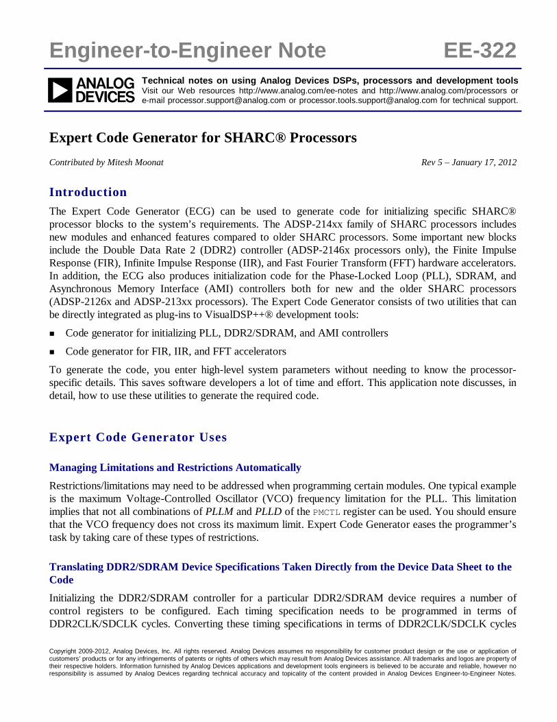
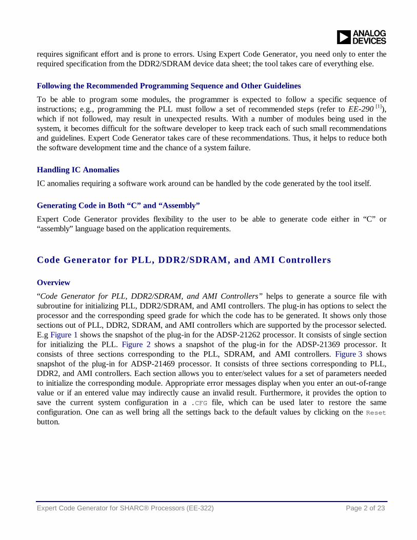
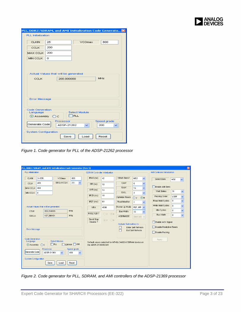
“Code Generator for PLL, DDR2/SDRAM, and AMI Controllers” helps to generate a source file with subroutine for initializing PLL, DDR2/SDRAM, and AMI controllers. The plug-in has options to select the processor and the corresponding speed grade for which the code has to be generated. It shows only those sections out of PLL, DDR2, SDRAM, and AMI controllers which are supported by the processor selected. E.g Figure 1 shows the snapshot of the plug-in for the ADSP-21262 processor. It consists of single section for initializing the PLL. Figure 2 shows a snapshot of the plug-in for the ADSP-21369 processor. It consists of three sections corresponding to the PLL, SDRAM, and AMI controllers. Figure 3 shows snapshot of the plug-in for ADSP-21469 processor. It consists of three sections corresponding to PLL, DDR2, and AMI controllers. Each section allows you to enter/select values for a set of parameters needed to initialize the corresponding module. Appropriate error messages display when you enter an out-of-range value or if an entered value may indirectly cause an invalid result. Furthermore, it provides the option to save the current system configuration in a .CFG file, which can be used later to restore the same configuration. One can as well bring all the settings back to the default values by clicking on the Reset button.
Expert Code Generator for SHARC® Processors (EE-322) Page 3 of 23
Figure 1. Code generator for PLL of the ADSP-21262 processor
Figure 2. Code generator for PLL, SDRAM, and AMI controllers of the ADSP-21369 processor
Expert Code Generator for SHARC® Processors (EE-322) Page 4 of 23
Figure 3. Code generator for PLL, DDR2, and AMI controllers of the 21469 processor
Registering and Accessing the Plug-In
To integrate the plug-in with the VisualDSP++ environment, perform the following steps:
1. Copy the PLL_DDR2_SDRAM_AMI_Init.dll file to the <install_path>\VisualDSP 5.0\System folder.
2. Copy the regsvr32.exe file from C:\WINDOWS\System32 to the folder mentioned above if this file is already not available.
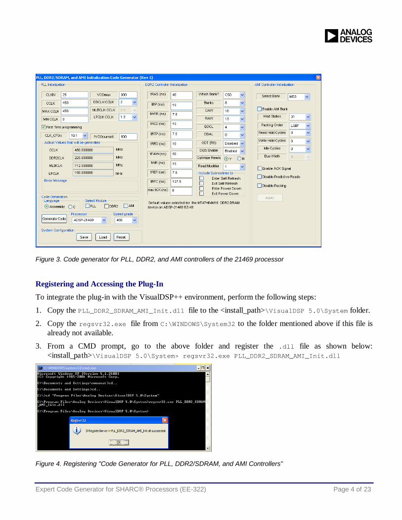
3. From a CMD prompt, go to the above folder and register the .dll file as shown below: <install_path>\VisualDSP 5.0\System> regsvr32.exe PLL_DDR2_SDRAM_AMI_Init.dll
Figure 4. Registering "Code Generator for PLL, DDR2/SDRAM, and AMI Controllers”
Expert Code Generator for SHARC® Processors (EE-322) Page 5 of 23
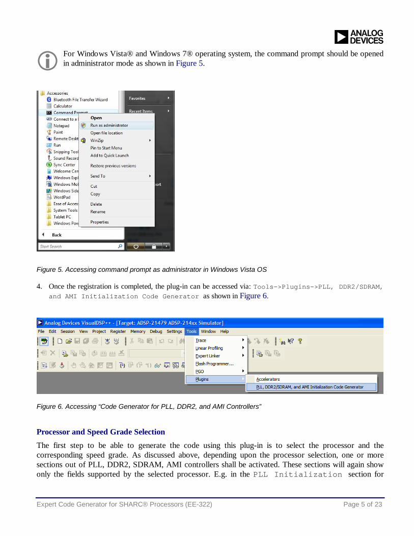
For Windows Vista® and Windows 7® operating system, the command prompt should be opened in administrator mode as shown in Figure 5.
Figure 5. Accessing command prompt as administrator in Windows Vista OS
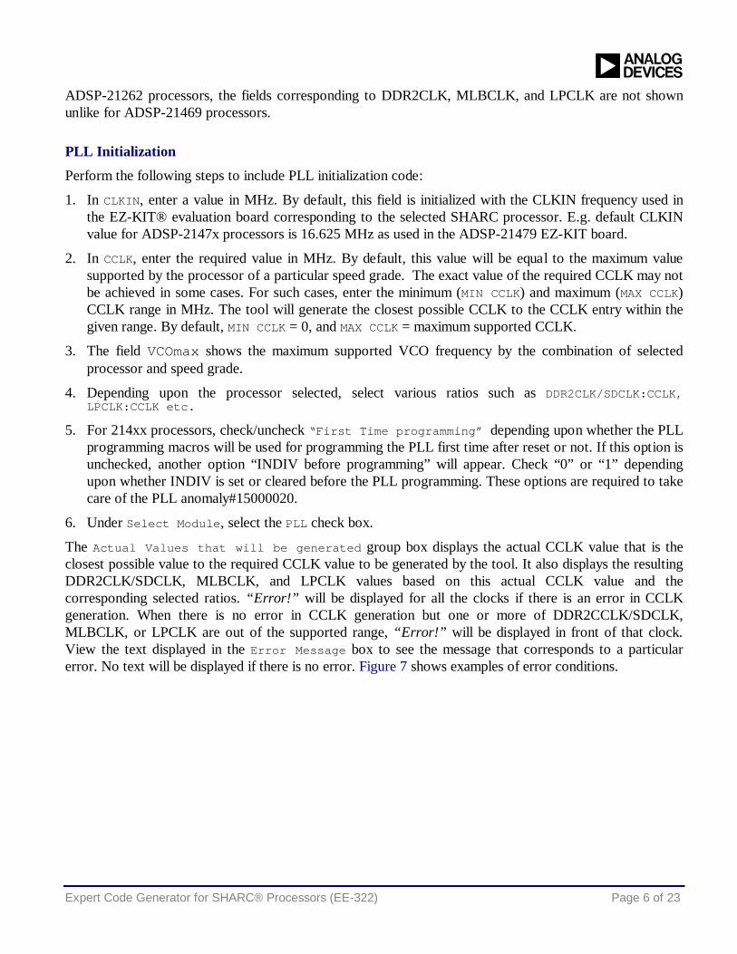
4. Once the registration is completed, the plug-in can be accessed via: Tools->Plugins->PLL, DDR2/SDRAM, and AMI Initialization Code Generator as shown in Figure 6.
Figure 6. Accessing “Code Generator for PLL, DDR2, and AMI Controllers”
Processor and Speed Grade Selection
The first step to be able to generate the code using this plug-in is to select the processor and the corresponding speed grade. As discussed above, depending upon the processor selection, one or more sections out of PLL, DDR2, SDRAM, AMI controllers shall be activated. These sections will again show only the fields supported by the selected processor. E.g. in the PLL Initialization section for
Expert Code Generator for SHARC® Processors (EE-322) Page 6 of 23
ADSP-21262 processors, the fields corresponding to DDR2CLK, MLBCLK, and LPCLK are not shown unlike for ADSP-21469 processors.
PLL Initialization
Perform the following steps to include PLL initialization code:
1. In CLKIN, enter a value in MHz. By default, this field is initialized with the CLKIN frequency used in the EZ-KIT® evaluation board corresponding to the selected SHARC processor. E.g. default CLKIN value for ADSP-2147x processors is 16.625 MHz as used in the ADSP-21479 EZ-KIT board.
2. In CCLK, enter the required value in MHz. By default, this value will be equal to the maximum value supported by the processor of a particular speed grade. The exact value of the required CCLK may not be achieved in some cases. For such cases, enter the minimum (MIN CCLK) and maximum (MAX CCLK) CCLK range in MHz. The tool will generate the closest possible CCLK to the CCLK entry within the given range. By default, MIN CCLK = 0, and MAX CCLK = maximum supported CCLK.
3. The field VCOmax shows the maximum supported VCO frequency by the combination of selected processor and speed grade.
4. Depending upon the processor selected, select various ratios such as DDR2CLK/SDCLK:CCLK, LPCLK:CCLK etc.
5. For 214xx processors, check/uncheck “First Time programming” depending upon whether the PLL programming macros will be used for programming the PLL first time after reset or not. If this option is unchecked, another option “INDIV before programming” will appear. Check “0” or “1” depending upon whether INDIV is set or cleared before the PLL programming. These options are required to take care of the PLL anomaly#15000020.
6. Under Select Module, select the PLL check box.
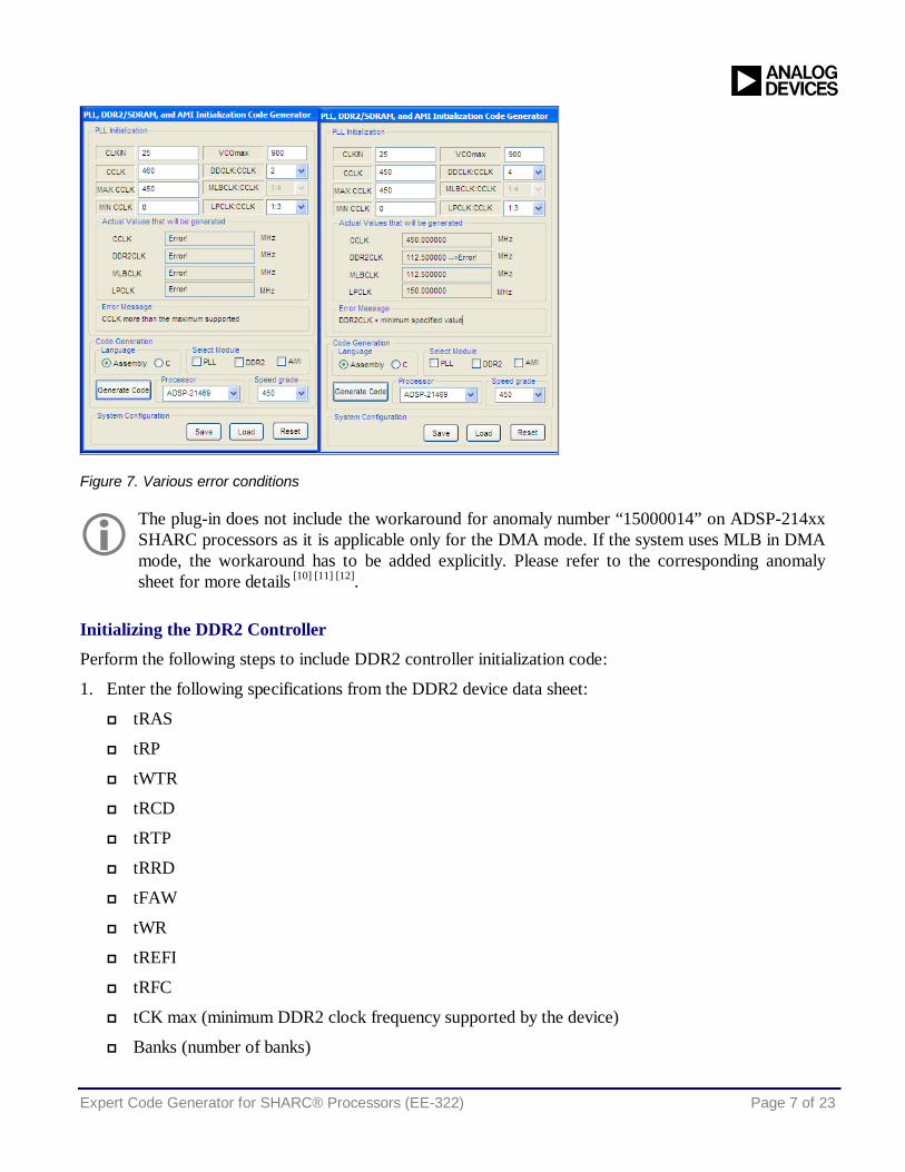
The Actual Values that will be generated group box displays the actual CCLK value that is the closest possible value to the required CCLK value to be generated by the tool. It also displays the resulting DDR2CLK/SDCLK, MLBCLK, and LPCLK values based on this actual CCLK value and the corresponding selected ratios. “Error!” will be displayed for all the clocks if there is an error in CCLK generation. When there is no error in CCLK generation but one or more of DDR2CCLK/SDCLK, MLBCLK, or LPCLK are out of the supported range, “Error!” will be displayed in front of that clock. View the text displayed in the Error Message box to see the message that corresponds to a particular error. No text will be displayed if there is no error. Figure 7 shows examples of error conditions.
Expert Code Generator for SHARC® Processors (EE-322) Page 7 of 23
Figure 7. Various error conditions
The plug-in does not include the workaround for anomaly number “15000014” on ADSP-214xx SHARC processors as it is applicable only for the DMA mode. If the system uses MLB in DMA mode, the workaround has to be added explicitly. Please refer to the corresponding anomaly sheet for more details [10] [11] [12].
Initializing the DDR2 Controller
Perform the following steps to include DDR2 controller initialization code:
1. Enter the following specifications from the DDR2 device data sheet:
tRAS
tRP
tWTR
tRCD
tRTP
tRRD
tFAW
tWR
tREFI
tRFC
tCK max (minimum DDR2 clock frequency supported by the device)
Banks (number of banks)
Expert Code Generator for SHARC® Processors (EE-322) Page 8 of 23
CAW (column address width)
RAW (row address width)
DDCL (CAS latency)
DDAL (additive latency)
2. In ODT (Rtt), Select Disabled to disable on-die termination, or select the corresponding value for Rtt.
3. In DQS Enable, select Enabled or Disabled according to the system’s requirements.
4. In Optimize Reads and Read Modifier, select Yes if predictive reads are needed, and select the corresponding modifier value.
5. In Which Bank, select the external port bank to which the DDR2 device should be mapped.
6. In Include Subroutines to, select options to generate separate subroutines for entering and exiting Self Refresh and Power Down modes. Corresponding options should be checked to generate these subroutines along with the PLL_DDR2_AMI subroutine.
7. Under Select Module, select the DDR2 check box.
Initializing the SDRAM Controller
1. Enter the following specifications from the SDRAM device data sheet:
tRAS
tRP
tWR
tRCD
tREF(SDRAM refresh period)
NRA (number of row addresses)
CAW (column address width)
RAW (row address width)
SDCL (CAS latency)
2. For ADSP-2137x, ADSP-2147x, and ADSP-2148x processors, select Yes for PGSZ 128 to set column width to 7 bits.
3. For ADSP-2137x processors, select Yes for Burst Stop Disable to disable burst stop.
4. In Optimize Reads and Read Modifier, select Yes if predictive reads are needed, and select the corresponding modifier value.
5. In Power Up Mode, select REF, MR Set for the power up mode “Precharge, mode reg set, 8CBR refresh cycles” else select MR Set, REF for the power up mode “Precharge, 8CBR refresh cycles, mode reg set”.
6. In Bus Width, select the bus width to be either 32 or 16 bits as per system requirements.
Expert Code Generator for SHARC® Processors (EE-322) Page 9 of 23
7. In Which Bank, select the external port bank to which the SDRAM should be mapped.
8. For ADSP-2147x and ADSP-2148x processors, in ADDRMODE, select the addressing mode to be page or bank interleaved.
9. In Include Subroutines to, select options to generate separate subroutines for entering and exiting Self Refresh mode.
10. Under Select Module, select the SDRAM check box.
Initializing the AMI Controller
The AMI Controller Initialization section of the GUI allows you to enable and configure one or more of the four AMI banks individually. To configure any AMI bank and include the AMI initialization code, perform the following steps:
1. In Select Bank, select the bank to be configured.
2. Select Enable AMI Bank, to enable this AMI bank.
3. Select the following parameters for this bank:
Wait States
Packing Order
Read Hold Cycles
Write Hold Cycles
Idle Cycles
Bus Width
Enable/Disable Packing
Enable/Disable Predictive Reads
Enable/Disable ACK Signal usage
4. Click Apply to save the settings for the current AMI bank selected.
5. Under Select Module, select the AMI check box.
Generating the Code
Once all the settings are entered and the required modules are selected, perform the following steps:
1. Under Language, select the Assembly button to generate the code in assembly, or select the C button to generate the code in C.
2. Click the Generate Code button to save the generated file in the required project folder. The default file name would be PLL_Init/PLL_SDRAM_AMI_Init/PLL_DDR2_AMI_Init.asm (or C) depending upon the processor selected.
Expert Code Generator for SHARC® Processors (EE-322) Page 10 of 23
Using the Generated Source File
Perform the following steps to use the generated source file in a VisualDSP++ project:
1. Add the generated file to the project.
2. In Assembly, declare the function _Init_PLL/_Init_PLL_DDR2_AMI/_Init_PLL_SDRAM_AMI.asm external using the .extern directive. Call the function whenever needed in the main code.
3. In C, declare the function Init_PLL()/Init_PLL_SDRAM_AMI()/Init_PLL_DDR2_AMI()external using the extern directive; Call the function whenever needed in the main code.
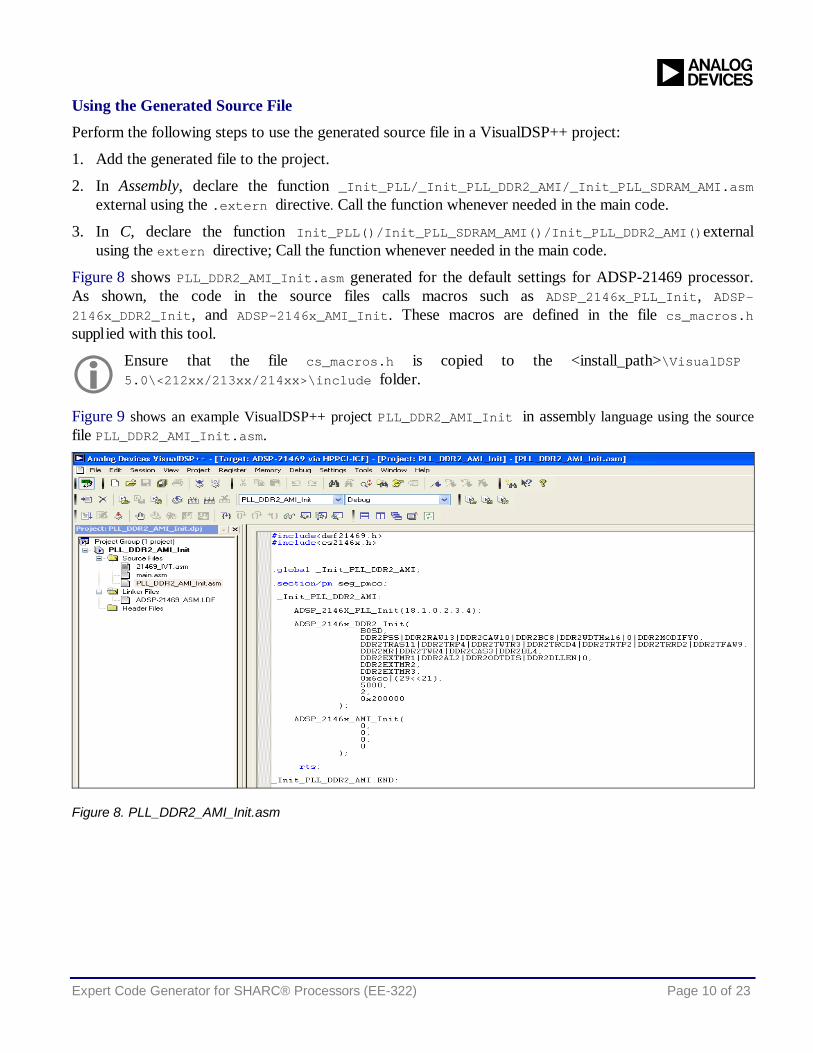
Figure 8 shows PLL_DDR2_AMI_Init.asm generated for the default settings for ADSP-21469 processor. As shown, the code in the source files calls macros such as ADSP_2146x_PLL_Init, ADSP-2146x_DDR2_Init, and ADSP-2146x_AMI_Init. These macros are defined in the file cs_macros.h supplied with this tool.
Ensure that the file cs_macros.h is copied to the <install_path>\VisualDSP 5.0\<212xx/213xx/214xx>\include folder.
Figure 9 shows an example VisualDSP++ project PLL_DDR2_AMI_Init in assembly language using the source file PLL_DDR2_AMI_Init.asm.
Figure 8. PLL_DDR2_AMI_Init.asm
Expert Code Generator for SHARC® Processors (EE-322) Page 11 of 23
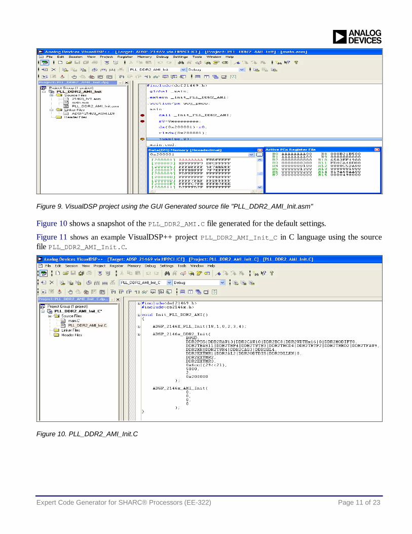
Figure 9. VisualDSP project using the GUI Generated source file "PLL_DDR2_AMI_Init.asm"
Figure 10 shows a snapshot of the PLL_DDR2_AMI.C file generated for the default settings.
Figure 11 shows an example VisualDSP++ project PLL_DDR2_AMI_Init_C in C language using the source file PLL_DDR2_AMI_Init.C.
Figure 10. PLL_DDR2_AMI_Init.C
Expert Code Generator for SHARC® Processors (EE-322) Page 12 of 23
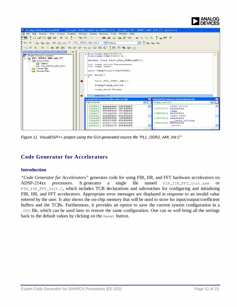
Figure 11. VisualDSP++ project using the GUI-generated source file "PLL_DDR2_AMI_Init.C"
Code Generator for Accelerators
Introduction
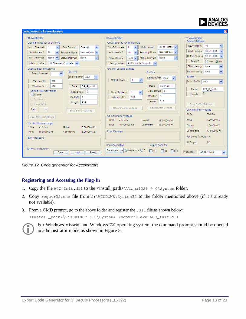
“Code Generator for Accelerators” generates code for using FIR, IIR, and FFT hardware accelerators on ADSP-214xx processors. It generates a single file named FIR_IIR_FFT_Init.asm or FIR_IIR_FFT_Init.C, which includes TCB declarations and subroutines for configuring and initializing FIR, IIR, and FFT accelerators. Appropriate error messages are displayed in response to an invalid value entered by the user. It also shows the on-chip memory that will be used to store for input/output/coefficient buffers and the TCBs. Furthermore, it provides an option to save the current system configuration in a .CFG file, which can be used later to restore the same configuration. One can as well bring all the settings back to the default values by clicking on the Reset button.
Expert Code Generator for SHARC® Processors (EE-322) Page 13 of 23
Figure 12. Code generator for Accelerators
Registering and Accessing the Plug-In
1. Copy the file ACC_Init.dll to the <install_path>\VisualDSP 5.0\System folder.
2. Copy regsvr32.exe file from C:\WINDOWS\System32 to the folder mentioned above (if it’s already not available).
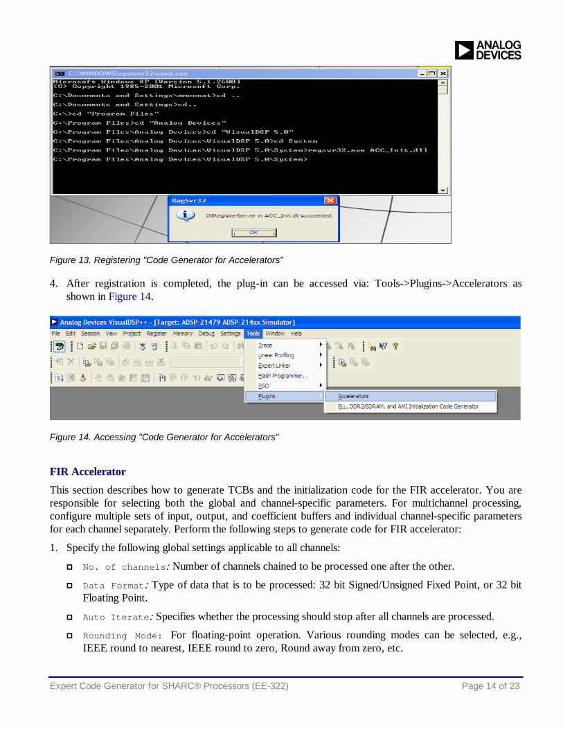
3. From a CMD prompt, go to the above folder and register the .dll file as shown below: <install_path>\VisualDSP 5.0\System> regsvr32.exe ACC_Init.dll
For Windows Vista® and Windows 7® operating system, the command prompt should be opened in administrator mode as shown in Figure 5.
Expert Code Generator for SHARC® Processors (EE-322) Page 14 of 23
Figure 13. Registering "Code Generator for Accelerators"
4. After registration is completed, the plug-in can be accessed via: Tools->Plugins->Accelerators as shown in Figure 14.
Figure 14. Accessing "Code Generator for Accelerators"
FIR Accelerator
This section describes how to generate TCBs and the initialization code for the FIR accelerator. You are responsible for selecting both the global and channel-specific parameters. For multichannel processing, configure multiple sets of input, output, and coefficient buffers and individual channel-specific parameters for each channel separately. Perform the following steps to generate code for FIR accelerator:
1. Specify the following global settings applicable to all channels:
No. of channels: Number of channels chained to be processed one after the other.
Data Format: Type of data that is to be processed: 32 bit Signed/Unsigned Fixed Point, or 32 bit Floating Point.
Auto Iterate: Specifies whether the processing should stop after all channels are processed.
Rounding Mode: For floating-point operation. Various rounding modes can be selected, e.g., IEEE round to nearest, IEEE round to zero, Round away from zero, etc.

Expert Code Generator for SHARC® Processors (EE-322) Page 15 of 23
Interrupt when: Interrupt can be generated either when processing of all channels or each channel is complete.
DMA Interrupt: “None” indicates that the DMA interrupt is not being used in the application. Select any of the 19 programmable interrupts from “P0I” to “P18I” to which this interrupt should be mapped.
Status Interrupt: “None” indicates that the DMA interrupt is not being used in the application. Select any of the 19 programmable interrupts from “P0I” to “P18I” to which this interrupt should be mapped.
2. Configure channel-specific settings:
Select Channel: Select the channel to be configured.
Tap Length: Enter the tap length for the FIR filter (<= 4096).
Window Size: Enter the number of output samples to be generated for one iteration (<= 1024).
Sample Rate Conversion: Select Enable if sample rate conversion is required.
Select whether Decimation or Interpolation is required.
Select the decimation/interpolation ratio.
3. Buffers: Configure following settings for the input/output/coefficient buffers:
Select Buffer: Select input/output/coefficient buffer for which setting is required.
Base: Default name is FIR_IP_Buffx/ FIR_OP_Buffx/ FIR_CF_Buffx (x = channel number). Enter a new name if the name of the buffer is different.
Index Offset: Enter the offset from where the processing needs to be started with regard to the base address.
Enter Modifier and Length.
Changing any field under Buffers enables the Save Buffer Settings button. Click this button to save the new settings. The button will be disabled automatically after it is clicked.
Changing any field under Channel Specific Settings (except Buffers) enables the Save Channel Settings button. Click this button to save the new settings. The button will be disabled automatically after it is clicked.
4. Under Include Code for, select the FIR check box.
Expert Code Generator for SHARC® Processors (EE-322) Page 16 of 23
IIR Accelerator
This section describes how to generate TCBs and the initialization code for the IIR accelerator. You are responsible for selecting both the global and channel-specific parameters. For multichannel processing, configure multiple sets of input, output, and coefficient buffers and individual channel-specific parameters for each channel separately. Perform the following steps to generate code for IIR accelerator:
1. Select following global settings applicable to all channels:
No. of channels: Number of channels chained to be processed one after the other.
Data Format: Type of data to be processed: 32/40 bit Floating Point.
Auto Iterate: Specifies whether the processing should stop after all channels are processed.
Rounding Mode: For floating-point operation. Various rounding modes can be selected, e.g., IEEE round to nearest, IEEE round to zero, Round away from zero, etc.
Interrupt when: Specifies whether an interrupt is generated when processing all channels or when each channel is complete.
DMA Interrupt: “None” indicates that the DMA interrupt is not being used in the application. Select any of the 19 programmable interrupts from “P0I” to “P18I” to which this interrupt should be mapped.
Status Interrupt: “None” indicates that the status interrupt is not being used in the application. Select any of the 19 programmable interrupts from “P0I” to “P18I” to which this interrupt should be mapped.
2. Configure channel-specific settings:
Select Channel: Specifies the channel to be configured. The total number of channels that needs to be configured will depend on the No. of channels value selected in the global settings. The total number of channels in the Select Channel option will be dynamically updated based on the No. of channels setting.
No of Biquads: Enter number of biquads for the IIR filter (<= 12).
Window Size: Enter the number of output samples to be generated for one iteration (<= 1024).
Buffers: Configure following settings for the input/output/coefficient buffers.
Select Buffer: Select Input/Output/Coefficient buffer for which setting is required.
Base: The default name is IIR_IP_Buffx/ IIR_OP_Buffx/ IIR_CF_Buffx (x = channel number). Enter a new name if the name of the buffer is different.
Index Offset: Enter the offset from where the processing needs to be started with regard to the base address.
Enter a Modifier and a Length.
Changing any field under Buffers enables the Save Buffer Settings button. Click this button to save the new settings. The button will be disabled automatically after it is clicked.
Expert Code Generator for SHARC® Processors (EE-322) Page 17 of 23
Changing any field under Channel Specific Settings (except Buffers) enables the Save Channel Settings button. Click this button to save the new settings. The button will be disabled automatically after it is clicked.
3. Under Include Code for, select the IIR check box.
FFT Accelerator
This section describes how to include TCBs and initialization code for FFT accelerator. Perform the following steps to include the FFT accelerator code:
1. General Settings:
No. of Points: Specify the number of FFT points required (2^k, 4<=k<=13).
Input Packing and Output Packing: Select the input and output packing format.
Select “R0, R1...I0 ,I1..” when input/output data is required in “first all real, then all imaginary” format.
Select “R0, I0, R1, I1..” when input/output data is required in “alternate real and imaginary” format.
NOTE: For FFT points>256, the packing format setting is ignored (i.e., input and output both use “alternate real and imaginary” format).
Repeat: Specify whether the processing needs to be repeated when done.
NOTE: You may have to add extra part of the code based on the application requirements when repeat mode is selected.
DMA Interrupt: Select “None” to indicate that the DMA interrupt is not being used in the application, or select any of the 19 programmable interrupts from “P0I” to “P18I” to which this interrupt should be mapped.
Status Interrupt: Select “None” to indicate that the status interrupt is not being used in the application, or select any of the 19 programmable interrupts from “P0I” to “P18I” to which this interrupt should be mapped.
2. Buffers:
Case 1: FFT Points (N) <=256: Following three buffers are required:
Input Buffer of size 2*N
Output Buffer of size 2*N
Coefficient Buffer of size 2*N
Case 2: FFT Points (N)>256: For points > 256, the FFT is calculated in three steps:
Compute V Point FFT. Store this result in an intermediate output buffer.
Multiply each of the elements of this output buffer with its corresponding special twiddle coefficients.
Compute H Point FFT of the resulting output buffer. This will give the final output buffer.
Expert Code Generator for SHARC® Processors (EE-322) Page 18 of 23
Because of this, following buffers are required:
i. Input Buffer of size 2*N.
ii. Output Buffer of size 2*N.
iii. Twiddle Coefficient Buffer for V Point FFT of size 2*V. (Value of V for a particular value of N will be displayed in the GUI itself.)
iv. Twiddle Coefficient Buffer for V Point FFT of size 2*H. (Value of V for a particular value of N will be displayed in the GUI itself.)
v. Intermediate output buffer to store the intermediate results of size 2*N.
vi. Special coefficient buffer of size 4*N.
Select Buffer: Select the buffer to be configured.
Name: Enter the name of the base of the buffer.
Length: The size of the buffers is fixed and not user-configurable. Thus, this field is read-only. You can view this field to see how much size to reserve for each buffer.
NOTE: To get the expected output, ensure that all the elements (2*N) of the input buffer are initialized.
Changing any field under Buffers enables the Save Buffer Settings button. Click this button to save the new settings. The button will be disabled automatically after it is clicked.
3. Under Include Code for, select the FFT check box.
Code Generation
Once all the settings are entered and the required modules are selected, perform the following steps to generate the code:
1. To generate the code in assembly, select the Assembly button under Language. To generate the code in C, select the C button under Language.
2. Click Generate Code button to save the generated file in the required project folder.
Using the Generated Source File
Perform the following steps to use the generated source file FIR_IIR_FFT_Init.asm or FIR_IIR_FFT_Init.C in a VisualDSP++ project:
1. Add the file FIR_IIR_FFT_Init.asm or FIR_IIR_FFT_Init.C to the project.
2. Assembly language
Declare the buffers to be used by the file FIR_IIR_FFT_Init.asm as global in the main source file, for example: global FIR_IP_buff1;
Declare the subroutine to be called from FIR_FFT_Init.asm as external, for example: .extern _Init_FIR;
Expert Code Generator for SHARC® Processors (EE-322) Page 19 of 23
Define and initialize all the buffers, and then call the _Init_FIR, _Init_IIR, or _Init_FFT function.
3. C language
Declare the buffers to be used by the file FIR_IIR_FFT_Init.C in global memory space in the main source file, for example: global FIR_IP_buff1[SIZE]={ #include “input.dat” };
Declare the subroutine to be called from FIR_FFT_Init.C as external, for example: .extern void_Init_FIR();
Once all the buffers are initialized, call the Init_FIR(), Init_IIR(), or Init_FFT() function.
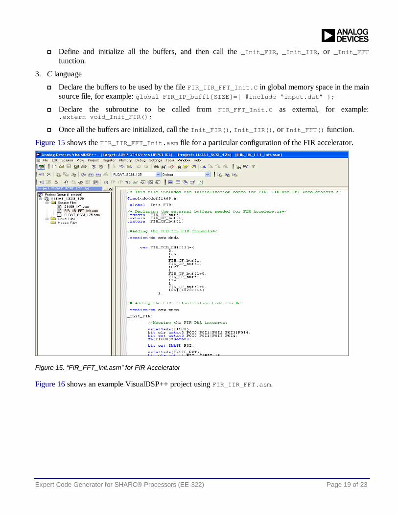
Figure 15 shows the FIR_IIR_FFT_Init.asm file for a particular configuration of the FIR accelerator.
Figure 15. “FIR_FFT_Init.asm” for FIR Accelerator
Figure 16 shows an example VisualDSP++ project using FIR_IIR_FFT.asm.
Expert Code Generator for SHARC® Processors (EE-322) Page 20 of 23
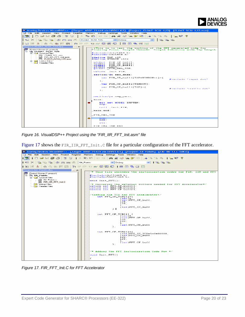
Figure 16. VisualDSP++ Project using the "FIR_IIR_FFT_Init.asm" file
Figure 17 shows the FIR_IIR_FFT_Init.C file for a particular configuration of the FFT accelerator.
Figure 17. FIR_FFT_Init.C for FFT Accelerator
Expert Code Generator for SHARC® Processors (EE-322) Page 21 of 23
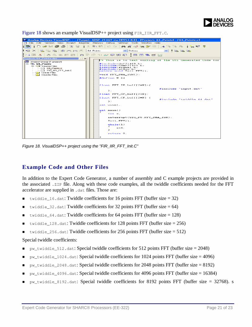
Figure 18 shows an example VisualDSP++ project using FIR_IIR_FFT.C.
Figure 18. VisualDSP++ project using the "FIR_IIR_FFT_Init.C"
Example Code and Other Files
In addition to the Expert Code Generator, a number of assembly and C example projects are provided in the associated .ZIP file. Along with these code examples, all the twiddle coefficients needed for the FFT accelerator are supplied in .dat files. Those are:
twiddle_16.dat: Twiddle coefficients for 16 points FFT (buffer size = 32)
twiddle_32.dat: Twiddle coefficients for 32 points FFT (buffer size = 64)
twiddle_64.dat: Twiddle coefficients for 64 points FFT (buffer size = 128)
twiddle_128.dat: Twiddle coefficients for 128 points FFT (buffer size = 256)
twiddle_256.dat: Twiddle coefficients for 256 points FFT (buffer size = 512)
Special twiddle coefficients:
pw_twiddle_512.dat: Special twiddle coefficients for 512 points FFT (buffer size = 2048)
pw_twiddle_1024.dat: Special twiddle coefficients for 1024 points FFT (buffer size = 4096)
pw_twiddle_2048.dat: Special twiddle coefficients for 2048 points FFT (buffer size = 8192)
pw_twiddle_4096.dat: Special twiddle coefficients for 4096 points FFT (buffer size = 16384)
pw_twiddle_8192.dat: Special twiddle coefficients for 8192 points FFT (buffer size = 32768). s
Expert Code Generator for SHARC® Processors (EE-322) Page 22 of 23
References [1] Managing the Core PLL on SHARC Processors (EE-290). Rev 4, November. Analog Devices, Inc.
[2] ADSP-2146x SHARC Processor Hardware Reference. Rev 0.3, July 2010. Analog Devices, Inc.
[3] ADSP-21261/ADSP-21262/ADSP-21266 SHARC Processor Data Sheet. Rev F, August 2009. Analog Devices, Inc.
[4] ADSP-21362/ADSP-21363/ADSP-21364/ADSP-21365/ADSP-21366 SHARC Processor data sheet. Rev G, March 2011. Analog Devices, Inc.
[5] ADSP-21367/ADSP-21368/ADSP-21369 SHARC Processors Data Sheet. Rev E, July 2009. Analog Devices, Inc.
[6] ADSP-21371/ADSP-21375 SHARC Processor Data Sheet. Rev C, September 2009. Analog Devices, Inc.
[7] ADSP-21467/ADSP-21469 SHARC Processor Data Sheet. Rev A, December, 2011. Analog Devices, Inc.
[8] ADSP-21478/ADSP-21479 SHARC Processor Data Sheet. Rev A, April 2011. Analog Devices, Inc.
[9] ADSP-21483/21486/21487/21488/21489 SHARC Processor Data Sheet. Rev 0, January 2011. Analog Devices, Inc.
[10] ADSP-21467/ADSP-21469 SHARC Anomaly List for Revisions 0.0. Rev F, November 2011. Analog Devices, Inc.
[11] ADSP-21478/ADSP-21479 SHARC Anomaly List for Revisions 0.0, 0.1, 0.2. Rev C, September 2011. Analog Devices, Inc.
[12] ADSP-21483/ADSP-21486/ADSP21487/ADSP-21488/ADSP-21489 SHARC Anomaly List for Revisions 0.1, 0.2. Rev F, September 2011. Analog Devices, Inc.
[13] MT48LC4M32B2 Data Sheet. Rev E, October, 2002. Micron Technology, Inc.
[14] MT48LC8M16A2 Data Sheet. Rev N, January 2009. Micron Technology, Inc.
[15] MT48LC16M16A2 Data Sheet. Rev N, January 2010. Micron Technology, Inc.
[16] MT47H64M16 Data Sheet. Rev P, January 2009, Micron Technology, Inc.
Expert Code Generator for SHARC® Processors (EE-322) Page 23 of 23
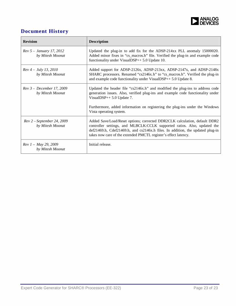
Document History
Revision Description
Rev 5 – January 17, 2012 by Mitesh Moonat
Updated the plug-in to add fix for the ADSP-214xx PLL anomaly 15000020. Added minor fixes in “cs_macros.h” file. Verified the plug-in and example code functionality under VisualDSP++ 5.0 Update 10.
Rev 4 – July 13, 2010 by Mitesh Moonat
Added support for ADSP-2126x, ADSP-213xx, ADSP-2147x, and ADSP-2148x SHARC processors. Renamed “cs2146x.h” to “cs_macros.h”. Verified the plug-in and example code functionality under VisualDSP++ 5.0 Update 8.
Rev 3 – December 17, 2009 by Mitesh Moonat
Updated the header file “cs2146x.h” and modified the plug-ins to address code generation issues. Also, verified plug-ins and example code functionality under VisualDSP++ 5.0 Update 7.
Furthermore, added information on registering the plug-ins under the Windows Vista operating system.
Rev 2 – September 24, 2009 by Mitesh Moonat
Added Save/Load/Reset options; corrected DDR2CLK calculation, default DDR2 controller settings, and MLBCLK:CCLK supported ratios. Also, updated the def21469.h, Cdef21469.h, and cs2146x.h files. In addition, the updated plug-in takes now care of the extended PMCTL register’s effect latency.
Rev 1 – May 29, 2009 by Mitesh Moonat
Initial release.
Related Documents