Experimenting with a Stellex YIG Oscillator Overview Stellex 6755-726 (Endwave MY01210) tunable mini-YIG oscillators are starting to show up on Ebay for around $20 to $40. Most of these YIGs cover the X-band frequency range, and without any tuning current are usually centered around 9 GHz. They are able to tune up or down approximately 1 GHz from this center frequency. YIG oscillators are just like regular Voltage Controlled Oscillators (VCO), except they require a constant tuning current rather than a constant voltage. This makes the YIG's driving circuit a little more complicated, but the final result will be a stable RF signal with low phase noise and around +12 dBm of output RF power. The driver circuit covered here will be a slightly altered version of the one shown in the RSGB's International Microwave Handbook. The concept of the YIG driver schematic is to convert a constant control voltage into a constant current that is running through one of the YIG's tuning connections. The Stellex 6755-726 YIG has a tuning sensitivity of around 5 MHz per milliamp of current flowing through its "tune" connection. Postive current flow increases the output frequency, while negative current flow reduces the output frequency. What this means, is that in order to tune a 9 GHz YIG up to the 10 GHz range, around 200 mA of positve current will need to flow through the YIG's tuning lines. The circuit to do this will need to be very stable (and low-noise) in order to maintain a clean and stable RF output. For this circuit, we'll be using LM627 (or OP27) low-noise op-amps to control a IRF510 MOSFET which is connected in series with the YIG's tuning lines. A simple feedback network will measure the voltage drop across a resistor and the op-amp's output will control the gate of the MOSFET which, in turn, regulates the current flowing through the YIG's tuning lines. Since the current limiting resistor used in this driver circuit is 10 ohms, the voltage drop across it will be 1 volt for every 100 mA of current flowing through the respective tuning line. As the voltage input to the op-amp's non-inverting pin increases, the current passed by the IRF510 will also increase. For example, say we measure 2 volts across the 10 ohm limiting resistor. This works out to that particular YIG line drawing 200 mA of current. This can be used as a test point to quickly check that the YIG's currents are at their proper settings. This model YIG also has the ability to be Frequency Modulated (FM) with a separate set of tuning lines. Modulating the YIG is basicaly the same as tuning the YIG, except the RF frequency range per milliamp of current is much smaller and the modulating signal will need to be on a DC offset when applied to the controlling op-amp. Bewere that the YIG's FM tuning lines can NOT handle alot of current flowing through them. You should try to keep the modulating current well under 200 mA. Note that using the FM driver with the YIG is optional if you just wish to have a CW RF source. Several versions of this YIG oscillator are available with an external PLL sythesizer for better frequency stability. John Miles, KE5FX, has some excellent documentation and PLL source code on his website at: www.thegleam.com/ke5fx/stellex.htm. It's a little more complicated than the free-running YIG driver shown here. 55

Welcome message from author
This document is posted to help you gain knowledge. Please leave a comment to let me know what you think about it! Share it to your friends and learn new things together.
Transcript
Experimenting with a Stellex YIG Oscillator
Overview
Stellex 6755−726 (Endwave MY01210) tunable mini−YIG oscillators are starting to show up onEbay for around $20 to $40. Most of these YIGs cover the X−band frequency range, and withoutany tuning current are usually centered around 9 GHz. They are able to tune up or downapproximately 1 GHz from this center frequency. YIG oscillators are just like regular VoltageControlled Oscillators (VCO), except they require a constant tuning current rather than a constantvoltage. This makes the YIG's driving circuit a little more complicated, but the final result will be astable RF signal with low phase noise and around +12 dBm of output RF power.
The driver circuit covered here will be a slightly altered version of the one shown in the RSGB'sInternational Microwave Handbook. The concept of the YIG driver schematic is to convert aconstant control voltage into a constant current that is running through one of the YIG's tuningconnections. The Stellex 6755−726 YIG has a tuning sensitivity of around 5 MHz per milliamp ofcurrent flowing through its "tune" connection. Postive current flow increases the output frequency,while negative current flow reduces the output frequency. What this means, is that in order to tunea 9 GHz YIG up to the 10 GHz range, around 200 mA of positve current will need to flow throughthe YIG's tuning lines. The circuit to do this will need to be very stable (and low−noise) in order tomaintain a clean and stable RF output. For this circuit, we'll be using LM627 (or OP27) low−noiseop−amps to control a IRF510 MOSFET which is connected in series with the YIG's tuning lines. Asimple feedback network will measure the voltage drop across a resistor and the op−amp's outputwill control the gate of the MOSFET which, in turn, regulates the current flowing through the YIG'stuning lines. Since the current limiting resistor used in this driver circuit is 10 ohms, the voltage dropacross it will be 1 volt for every 100 mA of current flowing through the respective tuning line. As thevoltage input to the op−amp's non−inverting pin increases, the current passed by the IRF510 willalso increase. For example, say we measure 2 volts across the 10 ohm limiting resistor. Thisworks out to that particular YIG line drawing 200 mA of current. This can be used as a test point toquickly check that the YIG's currents are at their proper settings.
This model YIG also has the ability to be Frequency Modulated (FM) with a separate set of tuninglines. Modulating the YIG is basicaly the same as tuning the YIG, except the RF frequency rangeper milliamp of current is much smaller and the modulating signal will need to be on a DC offsetwhen applied to the controlling op−amp. Bewere that the YIG's FM tuning lines can NOT handlealot of current flowing through them. You should try to keep the modulating current well under 200mA. Note that using the FM driver with the YIG is optional if you just wish to have a CW RF source.
Several versions of this YIG oscillator are available with an external PLL sythesizer for betterfrequency stability. John Miles, KE5FX, has some excellent documentation and PLL source codeon his website at: www.thegleam.com/ke5fx/stellex.htm. It's a little more complicated thanthe free−running YIG driver shown here.
55
Pictures & Construction Notes
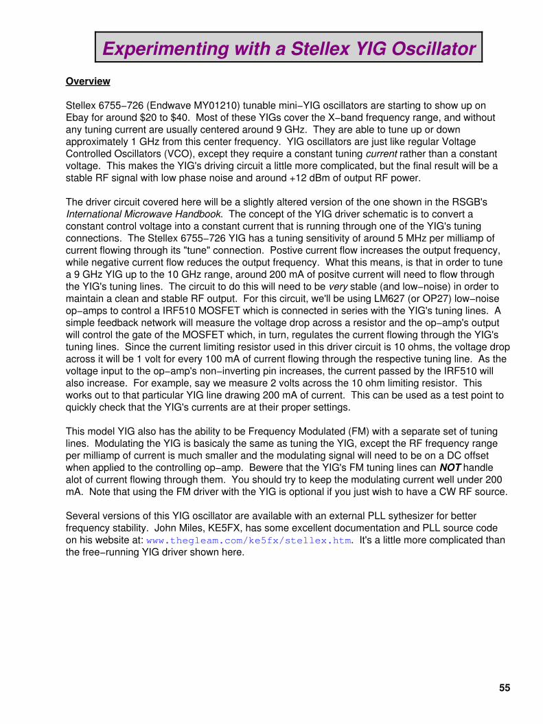
Mounting of the YIG and the tuning driver circuit board.
The YIG is mounted on a small piece of art foam to help avoid any microphonics fromvibrations. This stock Stellex 6755−726 YIG had a center frequency of 9.142 GHz with no tuningcurrent. Its RF output power was +11.6 dBm (14 mW).
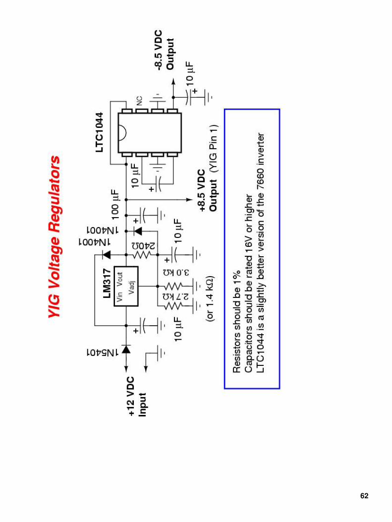
On the upper−right of the driver circuit board is a LM317 voltage regulator which provides a stable+8.5 VDC from the +12 VDC input. A LTC1044 negative voltage inverter generates the −8.5 VDCfor the negative rail on the op−amps. The tuning LM627 op−amp is on the lower portion of thecircuit board with a multiturn 5 kohm potentiometer for main frequency adjustment.
The Stellex 6755−726 YIG with this driver circuit could tune up to around 10.4 GHz. The YIG willget farily warm, so it's probably best not to run it at its full tuning current, so back it down to around10.0 to 10.1 GHz maximum.
Note that this driver and modulating circuit is still experimental and the first version broke intooscillation and required a little bit of tweaking to work properly. When I can get a chance to view theRF output on a spectrum analyzer, I'll be sure to document any necessary changes.
56
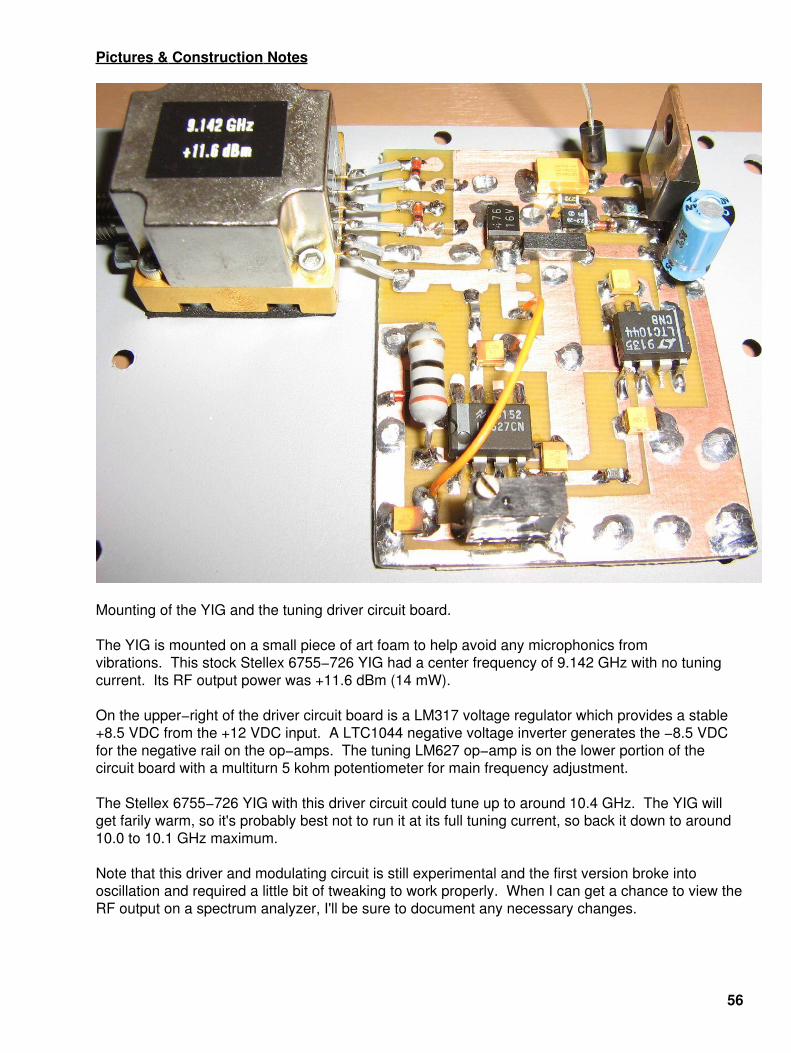
Alternate view.
The LM317 voltage regulator should have been mounted to a heatsink as it can get quite warm.
The pin−out on the Stellex 6755−726 YIG as shown, with pin 1 on the left:
Pin Function Wire Color1 +8.5 VDC Bias (120 mA) Red2 Ground Black3 Tune + Violet4 Tune − Orange5 FM + Yellow6 FM − Gray
The "Wire Color" refers to the hook−up wires attached to a stock Stellex YIG if you purchase themoff eBay.
Note that the violet wire (Tune +) has a series 15 ohm resistor.
57
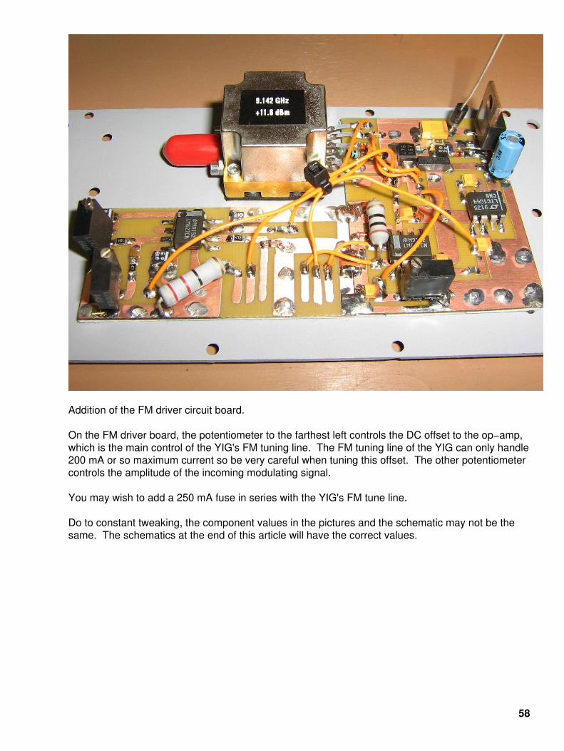
Addition of the FM driver circuit board.
On the FM driver board, the potentiometer to the farthest left controls the DC offset to the op−amp,which is the main control of the YIG's FM tuning line. The FM tuning line of the YIG can only handle200 mA or so maximum current so be very careful when tuning this offset. The other potentiometercontrols the amplitude of the incoming modulating signal.
You may wish to add a 250 mA fuse in series with the YIG's FM tune line.
Do to constant tweaking, the component values in the pictures and the schematic may not be thesame. The schematics at the end of this article will have the correct values.
58
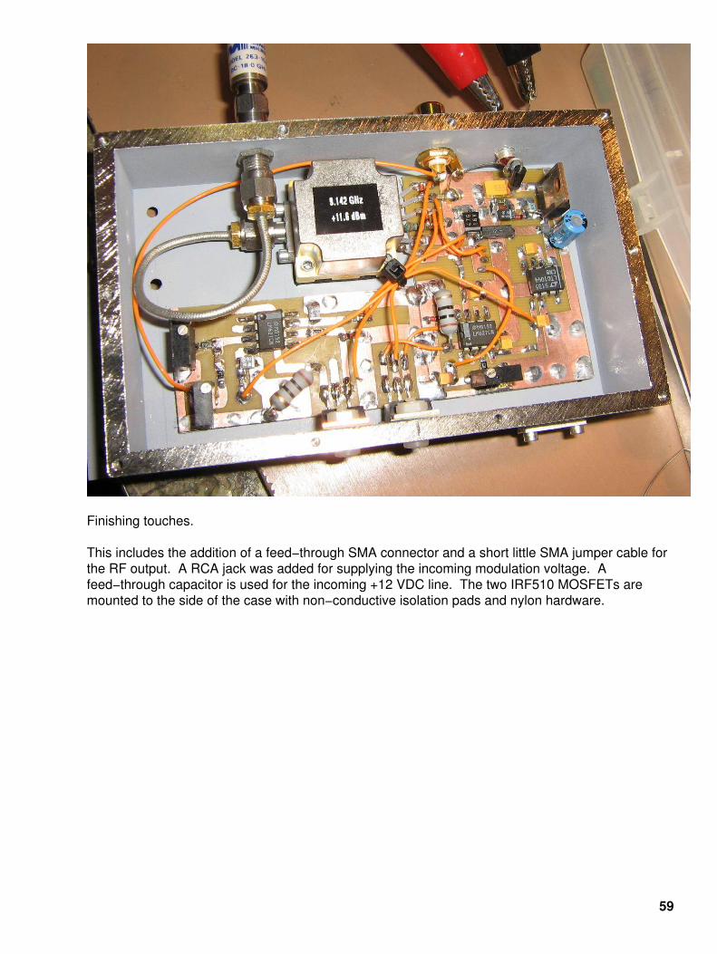
Finishing touches.
This includes the addition of a feed−through SMA connector and a short little SMA jumper cable forthe RF output. A RCA jack was added for supplying the incoming modulation voltage. Afeed−through capacitor is used for the incoming +12 VDC line. The two IRF510 MOSFETs aremounted to the side of the case with non−conductive isolation pads and nylon hardware.
59
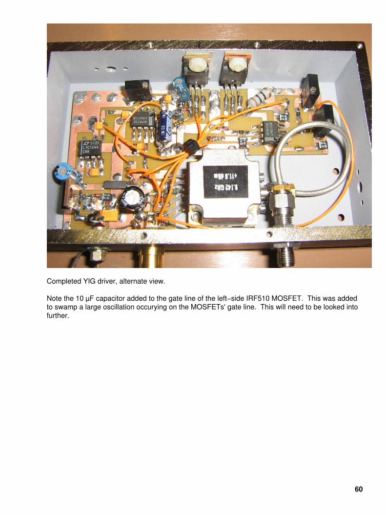
Completed YIG driver, alternate view.
Note the 10 µF capacitor added to the gate line of the left−side IRF510 MOSFET. This was addedto swamp a large oscillation occurying on the MOSFETs' gate line. This will need to be looked intofurther.
60

Completed case overview.
From left−to−right, +12 VDC input, modulating signal, and the RF output.
61
62

63

64
Related Documents