Purdue University Purdue e-Pubs International Refrigeration and Air Conditioning Conference School of Mechanical Engineering 2016 Experimental Study on Microchannel and Round Tube Plate Fin Evaporators in a Residential Air Conditioning System Huize Li University of Illinois at Urbana-Champaign, United States of America, [email protected] Pega Hrnjak [email protected] Follow this and additional works at: hp://docs.lib.purdue.edu/iracc is document has been made available through Purdue e-Pubs, a service of the Purdue University Libraries. Please contact [email protected] for additional information. Complete proceedings may be acquired in print and on CD-ROM directly from the Ray W. Herrick Laboratories at hps://engineering.purdue.edu/ Herrick/Events/orderlit.html Li, Huize and Hrnjak, Pega, "Experimental Study on Microchannel and Round Tube Plate Fin Evaporators in a Residential Air Conditioning System" (2016). International Reigeration and Air Conditioning Conference. Paper 1772. hp://docs.lib.purdue.edu/iracc/1772

Welcome message from author
This document is posted to help you gain knowledge. Please leave a comment to let me know what you think about it! Share it to your friends and learn new things together.
Transcript
Purdue UniversityPurdue e-PubsInternational Refrigeration and Air ConditioningConference School of Mechanical Engineering
2016
Experimental Study on Microchannel and RoundTube Plate Fin Evaporators in a Residential AirConditioning SystemHuize LiUniversity of Illinois at Urbana-Champaign, United States of America, [email protected]
Pega [email protected]
Follow this and additional works at: http://docs.lib.purdue.edu/iracc
This document has been made available through Purdue e-Pubs, a service of the Purdue University Libraries. Please contact [email protected] foradditional information.Complete proceedings may be acquired in print and on CD-ROM directly from the Ray W. Herrick Laboratories at https://engineering.purdue.edu/Herrick/Events/orderlit.html
Li, Huize and Hrnjak, Pega, "Experimental Study on Microchannel and Round Tube Plate Fin Evaporators in a Residential AirConditioning System" (2016). International Refrigeration and Air Conditioning Conference. Paper 1772.http://docs.lib.purdue.edu/iracc/1772
2472, Page 1
16th International Refrigeration and Air Conditioning Conference at Purdue, July 11-14, 2016
Experimental study on microchannel and round tube plate fin evaporators in a residential
air conditioning system
Huize LI1, Pega HRNJAK1,2*
1University of Illinois at Urbana-Champaign, Mechanical Science and Engineering,
Urbana, IL, USA
[email protected], [email protected]
2CTS, Creative Thermal Solutions, Urbana, IL, USA
* Corresponding Author
ABSTRACT
The performance of two evaporators (round tube plate fin and microchannel) and their effect on system
performances were experimentally investigated in R410A residential air conditioning systems. Both systems share
identical components except evaporators and system performance were measured under AHRI A, B and C
conditions. Under all test conditions, the system with the microchannel evaporator outperformed the baseline system
with the round tube plate fin evaporator. Up to 10.6% increase of capacity and 13.1% increase of COP were
achieved if both systems were operated under the same compressor speed. Up to 23.8% improvement of COP was
obtained if the cooling capacities of both systems were kept the same. The refrigerant charge was reduced by 13.4%
compared with the baseline system, due to the smaller internal volume of the microchannel evaporator. The air side
heat transfer area of microchannel evaporator was just ½ of the baseline round tube plate fin evaporator, and so was
the face area.
1. INTRODUCTION
In residential air conditioning systems, round tube plate fin (RTPF) heat exchangers are more widely used than
microchannel heat exchangers probably because of tradition and some say because of the cost advantage. Under
increasingly tighter regulation of energy efficiency, microchannel heat exchangers, as a potential solution for
efficiency improvement, start to draw more attention from the residential air conditioning industry. The major
advantages of microchannel heat exchangers over RTPF heat exchanger are compactness and enhancement of heat
transfer. These advantages can lead to reduction of refrigerant charge and material used in manufacturing. Some say
that the cost can be also lower due to design without currently very costly copper.
Park and Hrnjak (2008) used a microchannel condenser to replace the original RTPF condenser. The face area and
air-side heat transfer area of both heat exchangers are similar. The system with microchannel condenser had 13.1%
higher COP than the system with RTPF condenser under AHRI condition A. The system charge was also reduced by
9.2%. Qi et al,. (2009a) investigated the possibility of replacing a plate fin evaporator which is commonly used in
automotive air conditioning systems by a microchannel evaporator. The microchannel evaporator is 17.2% smaller
in volume and 2.8% lighter in weight. 4.3% higher heat transfer rate and more uniform air exit temperature
distribution was achieved by the microchannel heat exchanger, at the penalty of slightly higher refrigerant side and
air side pressure drop. Qi et al,. (2009b) replaced the plate fin evaporator and microchannel condenser in the
baseline system with a microchannel evaporator and a microchannel condenser with a designated subcooling path.
The microchannel evaporator and plate fin evaporator were the ones used in Qi et al., (2009a). Compared with the
baseline, the new condenser is 15.1% smaller and 14.9% lighter. Charge in the system was reduced by 4%. Cooling
capacity and COP was increased by 5% and 7.9% under 3000 rpm driving condition.
2472, Page 2
16th International Refrigeration and Air Conditioning Conference at Purdue, July 11-14, 2016
In this study, two evaporators (one is RTPF and the other is microchannel) with similar rated capacity were tested in
the same facility. The system performances were compared and the advantage of microchannel evaporator was
identified.
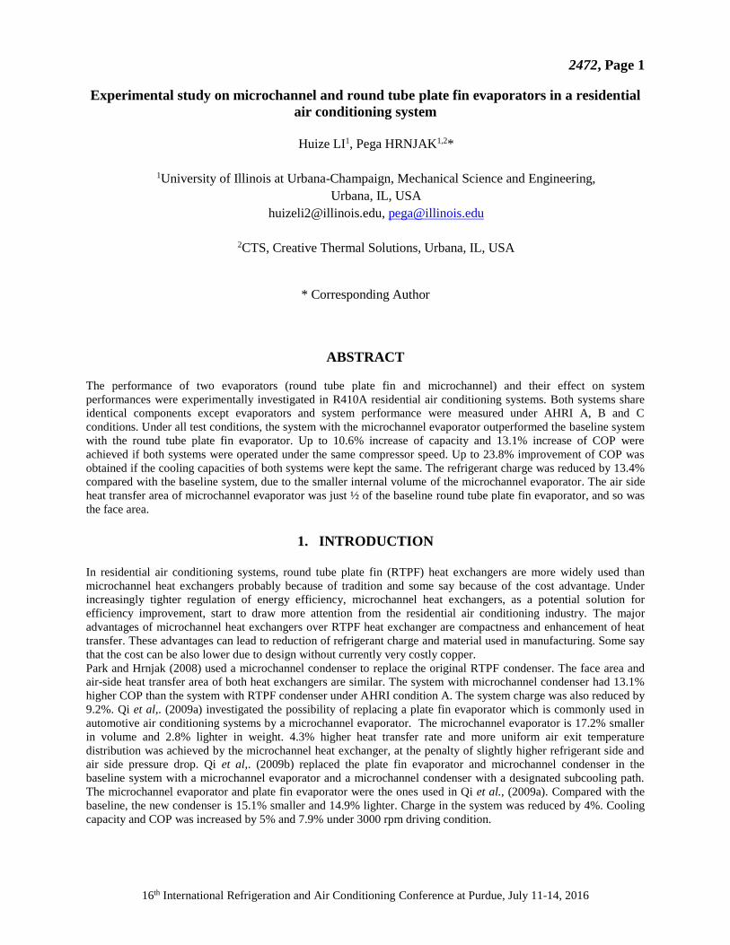
2. EXPERIMENTAL SETUP AND TEST CONDITIONS
The experimental setup consists of two environmental chambers which are used to simulate indoor and outdoor
conditions. One insulated wind tunnel is placed in each chamber, and each wind tunnel is equipped with a variable
speed blower to simulate different air flow rate conditions. Figure 1 shows the schematic of the experimental
facility. The uncertainties of measurements are summarized in Table 1. The uncertainties for capacity and COP are
calculated by the method proposed by Moffat (1988), which are ±3% (both refrigerant side and air side) and ±5%
respectively.
Table 1: Instruments and uncertainties of measurements
Measurement Unit Uncertainty
Temperature ℃ ±0.5
Refrigerant pressure kPa ±0.11%
Refrigerant pressure Drop kPa ±0.25%
Nozzle pressure drop Pa ±1%
Air-side HX pressure drop Pa ±1%
Refrigerant mass flow rate g/s ±0.5%
Compressor power kW ±0.2%
Figure 1: Schematic of experimental facility
The original system containing a RTPF evaporator is a high efficiency off the shelf residential system which can be
used for both AC and HP. It has a rated capacity of 7kW and up to 20.5 SEER cooling efficiency. The evaporator
unit has an A-shaped RTPF evaporator and an installed thermal expansion valve (TXV). The condenser unit has a
RTPF condenser, variable speed scroll compressor and an accumulator. The system was tested under three
2472, Page 3
16th International Refrigeration and Air Conditioning Conference at Purdue, July 11-14, 2016
conditions (A, B and C) from AHRI Standard (2008). The details of the conditions are summarized in Table 2.
Under AHRI conditions A and B, which are wet, dewpoint monitors were used to control humidifiers to achieve the
required humidity in the indoor chamber.
Table 2. Test conditions for the systems of interest
Test Description Air entering indoor unit temperature (℃) Air entering outdoor unit temperature (℃)
Dry-Bulb Wet-Bulb Dry-Bulb Wet-Bulb
A 26.7 19.4 35 (b)
B 26.7 19.4 27.8 (b)
C 26.7 (a) 27.8 (b)
(a) Wet-bulb temperature is low enough that there is no condensation on the indoor coil.
(b) The wet-bulb temperature is not required if the unit does not reject condensate to the outdoor coil.
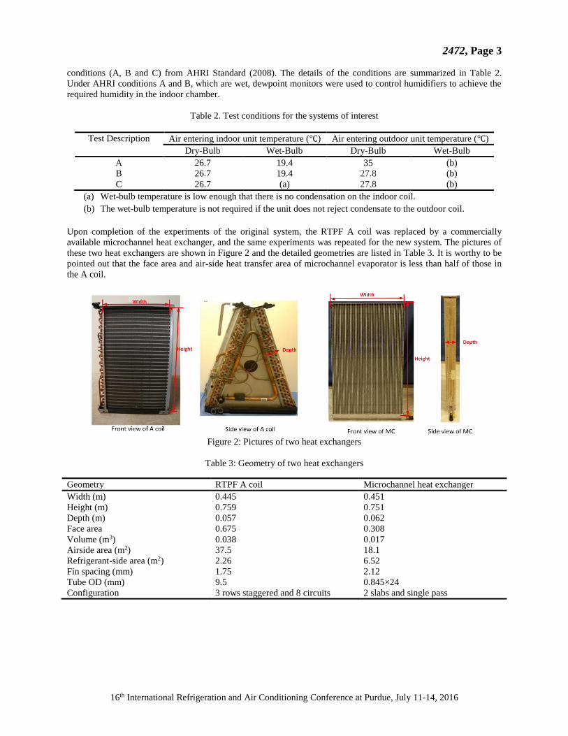
Upon completion of the experiments of the original system, the RTPF A coil was replaced by a commercially
available microchannel heat exchanger, and the same experiments was repeated for the new system. The pictures of
these two heat exchangers are shown in Figure 2 and the detailed geometries are listed in Table 3. It is worthy to be
pointed out that the face area and air-side heat transfer area of microchannel evaporator is less than half of those in
the A coil.
Figure 2: Pictures of two heat exchangers
Table 3: Geometry of two heat exchangers
Geometry RTPF A coil Microchannel heat exchanger
Width (m) 0.445 0.451
Height (m) 0.759 0.751
Depth (m) 0.057 0.062
Face area 0.675 0.308
Volume (m3) 0.038 0.017
Airside area (m2) 37.5 18.1
Refrigerant-side area (m2) 2.26 6.52
Fin spacing (mm) 1.75 2.12
Tube OD (mm) 9.5 0.845×24
Configuration 3 rows staggered and 8 circuits 2 slabs and single pass
2472, Page 4
16th International Refrigeration and Air Conditioning Conference at Purdue, July 11-14, 2016
3. EXPERIMENTAL RESULTS
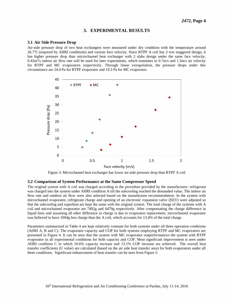
3.1 Air Side Pressure Drop
Air-side pressure drop of two heat exchangers were measured under dry condition with the temperature around
26.7℃ (required by AHRI conditions) and various face velocity. Since RTPF A coil has 3 row staggered design, it
has higher pressure drop than microchannel heat exchanger with 2 slabs design under the same face velocity.
0.42m3/s indoor air flow rate will be used for later experiments, which translates to 0.7m/s and 1.3m/s air velocity
for RTPF and MC evaporators respectively. Through linear extrapolation, the pressure drops under this
circumstance are 24.4 Pa for RTPF evaporator and 19.3 Pa for MC evaporator.
Figure 3: Microchannel heat exchanger has lower air-side pressure drop than RTPF A coil
3.2 Comparison of System Performance at the Same Compressor Speed
The original system with A coil was charged according to the procedure provided by the manufacturer: refrigerant
was charged into the system under AHRI condition A till the subcooling reached the demanded value. The indoor air
flow rate and outdoor air flow were also selected based on the manufacture recommendation. In the system with
microchannel evaporator, refrigerant charge and opening of an electronic expansion valve (EEV) were adjusted so
that the subcooling and superheat are kept the same with the original system. The total charge of the systems with A
coil and microchannel evaporator are 7492g and 6479g respectively. After compensating the charge difference in
liquid lines and assuming all other difference in charge is due to evaporator replacement, microchannel evaporator
was believed to have 1004g less charge than the A coil, which accounts for 13.4% of the total charge.
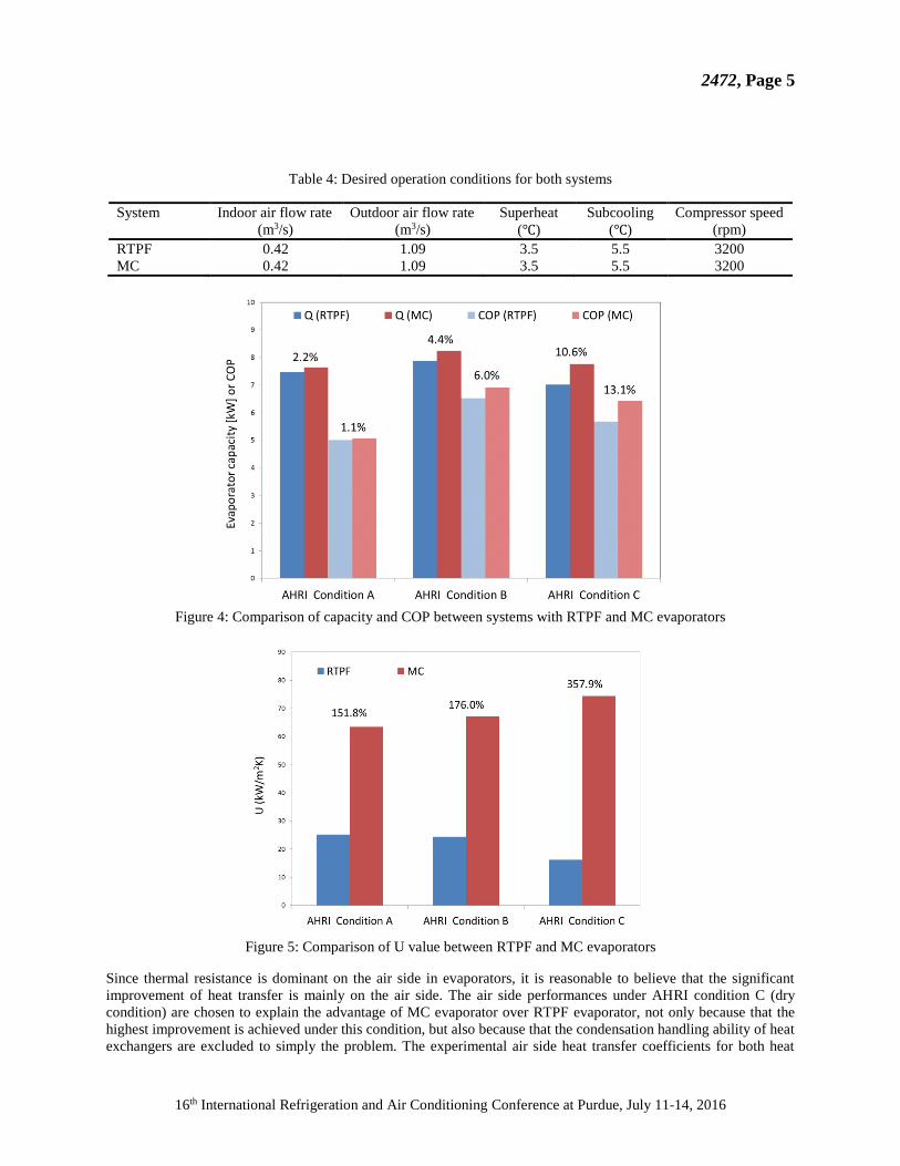
Parameters summarized in Table 4 are kept relatively constant for both systems under all three operation conditions
(AHRI A, B and C). The evaporator capacity and COP for both systems employing RTPF and MC evaporators are
presented in Figure 4. It can be seen that the system with MC evaporator outperformances the system with RTPF
evaporator in all experimental conditions for both capacity and COP. Most significant improvement is seen under
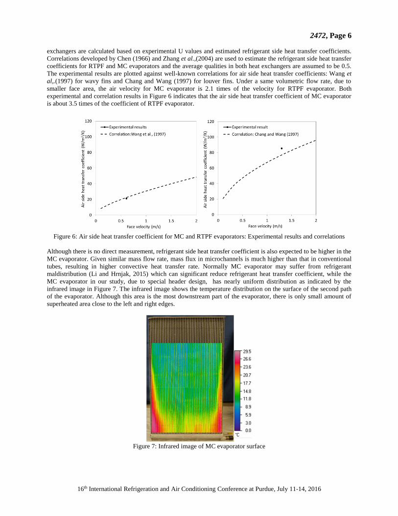
AHRI condition C in which 10.6% capacity increase and 13.1% COP increase are achieved. The overall heat
transfer coefficients (U value) are calculated (based on the air side heat transfer area) for both evaporators under all
three conditions. Significant enhancement of heat transfer can be seen from Figure 5.
2472, Page 5
16th International Refrigeration and Air Conditioning Conference at Purdue, July 11-14, 2016
Table 4: Desired operation conditions for both systems
System Indoor air flow rate
(m3/s)
Outdoor air flow rate
(m3/s)
Superheat
(℃)
Subcooling
(℃)
Compressor speed
(rpm)
RTPF 0.42 1.09 3.5 5.5 3200
MC 0.42 1.09 3.5 5.5 3200
Figure 4: Comparison of capacity and COP between systems with RTPF and MC evaporators
Figure 5: Comparison of U value between RTPF and MC evaporators
Since thermal resistance is dominant on the air side in evaporators, it is reasonable to believe that the significant
improvement of heat transfer is mainly on the air side. The air side performances under AHRI condition C (dry
condition) are chosen to explain the advantage of MC evaporator over RTPF evaporator, not only because that the
highest improvement is achieved under this condition, but also because that the condensation handling ability of heat
exchangers are excluded to simply the problem. The experimental air side heat transfer coefficients for both heat
2472, Page 6
16th International Refrigeration and Air Conditioning Conference at Purdue, July 11-14, 2016
exchangers are calculated based on experimental U values and estimated refrigerant side heat transfer coefficients.
Correlations developed by Chen (1966) and Zhang et al.,(2004) are used to estimate the refrigerant side heat transfer
coefficients for RTPF and MC evaporators and the average qualities in both heat exchangers are assumed to be 0.5.
The experimental results are plotted against well-known correlations for air side heat transfer coefficients: Wang et
al,.(1997) for wavy fins and Chang and Wang (1997) for louver fins. Under a same volumetric flow rate, due to
smaller face area, the air velocity for MC evaporator is 2.1 times of the velocity for RTPF evaporator. Both
experimental and correlation results in Figure 6 indicates that the air side heat transfer coefficient of MC evaporator
is about 3.5 times of the coefficient of RTPF evaporator.
Figure 6: Air side heat transfer coefficient for MC and RTPF evaporators: Experimental results and correlations
Although there is no direct measurement, refrigerant side heat transfer coefficient is also expected to be higher in the
MC evaporator. Given similar mass flow rate, mass flux in microchannels is much higher than that in conventional
tubes, resulting in higher convective heat transfer rate. Normally MC evaporator may suffer from refrigerant
maldistribution (Li and Hrnjak, 2015) which can significant reduce refrigerant heat transfer coefficient, while the
MC evaporator in our study, due to special header design, has nearly uniform distribution as indicated by the
infrared image in Figure 7. The infrared image shows the temperature distribution on the surface of the second path
of the evaporator. Although this area is the most downstream part of the evaporator, there is only small amount of
superheated area close to the left and right edges.
Figure 7: Infrared image of MC evaporator surface
2472, Page 7
16th International Refrigeration and Air Conditioning Conference at Purdue, July 11-14, 2016
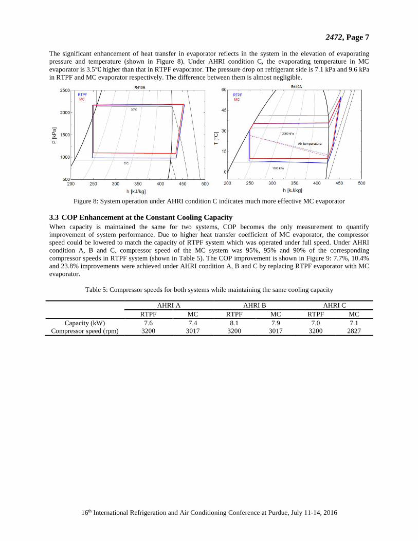
The significant enhancement of heat transfer in evaporator reflects in the system in the elevation of evaporating
pressure and temperature (shown in Figure 8). Under AHRI condition C, the evaporating temperature in MC
evaporator is 3.5℃ higher than that in RTPF evaporator. The pressure drop on refrigerant side is 7.1 kPa and 9.6 kPa
in RTPF and MC evaporator respectively. The difference between them is almost negligible.
Figure 8: System operation under AHRI condition C indicates much more effective MC evaporator
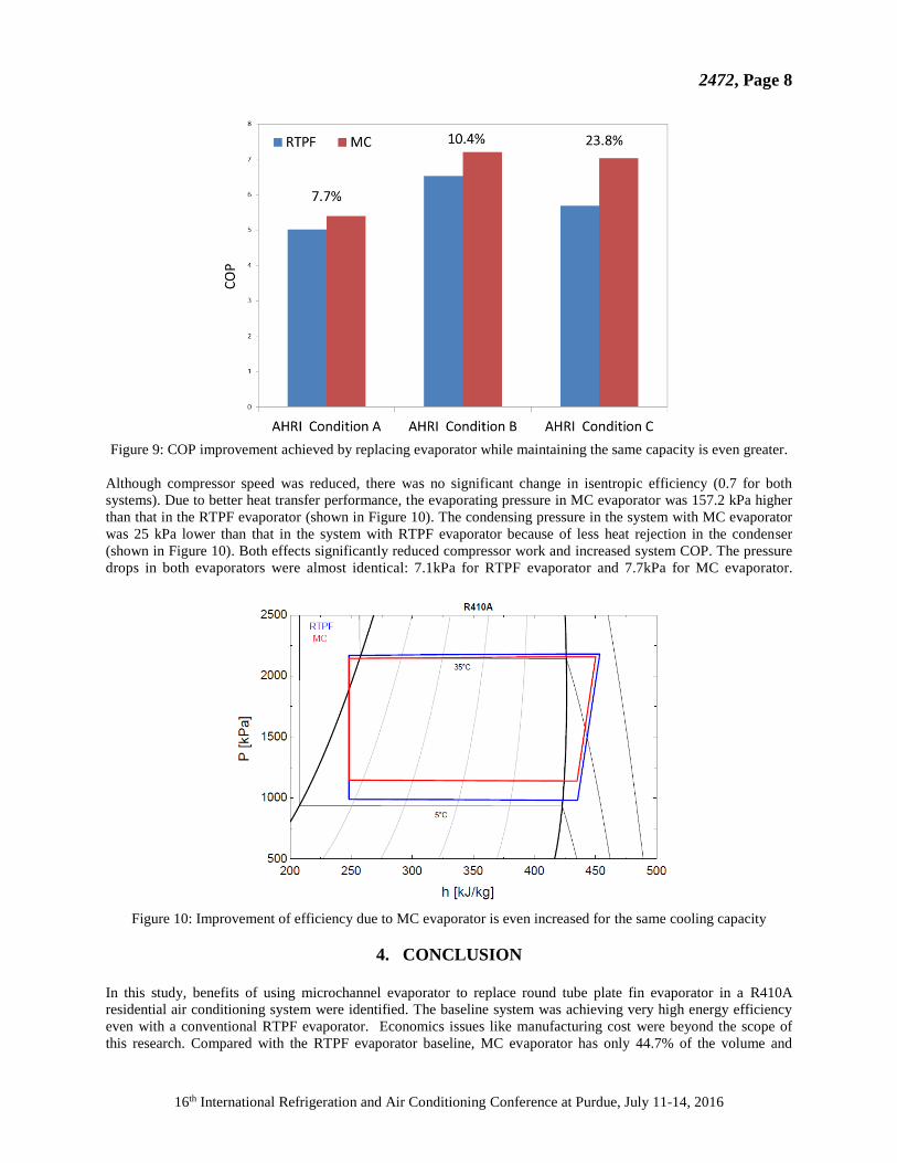
3.3 COP Enhancement at the Constant Cooling Capacity
When capacity is maintained the same for two systems, COP becomes the only measurement to quantify
improvement of system performance. Due to higher heat transfer coefficient of MC evaporator, the compressor
speed could be lowered to match the capacity of RTPF system which was operated under full speed. Under AHRI
condition A, B and C, compressor speed of the MC system was 95%, 95% and 90% of the corresponding
compressor speeds in RTPF system (shown in Table 5). The COP improvement is shown in Figure 9: 7.7%, 10.4%
and 23.8% improvements were achieved under AHRI condition A, B and C by replacing RTPF evaporator with MC
evaporator.
Table 5: Compressor speeds for both systems while maintaining the same cooling capacity
AHRI A AHRI B AHRI C
RTPF MC RTPF MC RTPF MC
Capacity (kW) 7.6 7.4 8.1 7.9 7.0 7.1
Compressor speed (rpm) 3200 3017 3200 3017 3200 2827
2472, Page 8
16th International Refrigeration and Air Conditioning Conference at Purdue, July 11-14, 2016
Figure 9: COP improvement achieved by replacing evaporator while maintaining the same capacity is even greater.
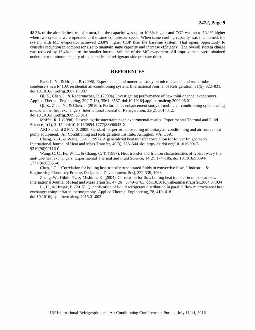
Although compressor speed was reduced, there was no significant change in isentropic efficiency (0.7 for both
systems). Due to better heat transfer performance, the evaporating pressure in MC evaporator was 157.2 kPa higher
than that in the RTPF evaporator (shown in Figure 10). The condensing pressure in the system with MC evaporator
was 25 kPa lower than that in the system with RTPF evaporator because of less heat rejection in the condenser
(shown in Figure 10). Both effects significantly reduced compressor work and increased system COP. The pressure
drops in both evaporators were almost identical: 7.1kPa for RTPF evaporator and 7.7kPa for MC evaporator.
Figure 10: Improvement of efficiency due to MC evaporator is even increased for the same cooling capacity
4. CONCLUSION
In this study, benefits of using microchannel evaporator to replace round tube plate fin evaporator in a R410A
residential air conditioning system were identified. The baseline system was achieving very high energy efficiency
even with a conventional RTPF evaporator. Economics issues like manufacturing cost were beyond the scope of
this research. Compared with the RTPF evaporator baseline, MC evaporator has only 44.7% of the volume and
2472, Page 9
16th International Refrigeration and Air Conditioning Conference at Purdue, July 11-14, 2016
48.3% of the air side heat transfer area, but the capacity was up to 10.6% higher and COP was up to 13.1% higher
when two systems were operated at the same compressor speed. When same cooling capacity was maintained, the
system with MC evaporator achieved 23.8% higher COP than the baseline system. That opens opportunity to
consider reduction in compressor size to maintain same capacity and increase efficiency. The overall system charge
was reduced by 13.4% due to the smaller internal volume of the MC evaporator. All improvement were obtained
under no or minimum penalty of the air side and refrigerant side pressure drop.
REFERENCES
Park, C. Y., & Hrnjak, P. (2008). Experimental and numerical study on microchannel and round-tube
condensers in a R410A residential air-conditioning system. International Journal of Refrigeration, 31(5), 822–831.
doi:10.1016/j.ijrefrig.2007.10.007
Qi, Z., Chen, J., & Radermacher, R. (2009a). Investigating performance of new mini-channel evaporators.
Applied Thermal Engineering, 29(17-18), 3561–3567. doi:10.1016/j.applthermaleng.2009.06.011
Qi, Z., Zhao, Y., & Chen, J. (2010b). Performance enhancement study of mobile air conditioning system using
microchannel heat exchangers. International Journal of Refrigeration, 33(2), 301–312.
doi:10.1016/j.ijrefrig.2009.08.014
Moffat, R. J. (1988). Describing the uncertainties in experimental results. Experimental Thermal and Fluid
Science, 1(1), 3–17. doi:10.1016/0894-1777(88)90043-X
ARI Standard 210/240, 2008. Standard for performance rating of unitary air conditioning and air source heat
pump equipment. Air Conditioning and Refrigeration Institute, Arlington, VA, USA.
Chang, Y.-J., & Wang, C.-C. (1997). A generalized heat transfer correlation for Iouver fin geometry.
International Journal of Heat and Mass Transfer, 40(3), 533–544. doi:http://dx.doi.org/10.1016/0017-
9310(96)00116-0
Wang, C. C., Fu, W. L., & Chang, C. T. (1997). Heat transfer and friction characteristics of typical wavy fin-
and-tube heat exchangers. Experimental Thermal and Fluid Science, 14(2), 174–186. doi:10.1016/S0894-
1777(96)00056-8
Chen, J.C., "Correlation for boiling heat transfer to saturated fluids in convective flow, " Industrial &
Engineering Chemistry Process Design and Development. 5(3), 322-339, 1966.
Zhang, W., Hibiki, T., & Mishima, K. (2004). Correlation for flow boiling heat transfer in mini-channels.
International Journal of Heat and Mass Transfer, 47(26), 5749–5763. doi:10.1016/j.ijheatmasstransfer.2004.07.034
Li, H., & Hrnjak, P. (2015). Quantification of liquid refrigerant distribution in parallel flow microchannel heat
exchanger using infrared thermography. Applied Thermal Engineering, 78, 410–418.
doi:10.1016/j.applthermaleng.2015.01.003
Related Documents