ICSV14 Cairns • Australia 9-12 July, 2007 EXPERIMENTAL STUDY OF THE FLAME CONE KINEMATICS OF ACOUSTICALLY PERTURBED PREMIXED LAMINAR BUNSEN FLAMES V. N. Kornilov, K.R.A.M. Schreel and L. P. H. de Goey Eindhoven University of Technology faculty of Mechanical Engineering, group of Combustion Technology PO Box 513, WH 2.144, 5600 MB Eindhoven, The Netherlands [email protected] Abstract The results of a spatially and temporally resolved experimental study of the conical flame front kinematics of acoustically excited flames are presented. The basic assumptions which are widely used in theoretical flame kinematics considerations are verified experimentally. The propagation velocity and spatial evolution of the flame front disturbances are measured. Special attention is paid to the character of the flame end point motion. An elliptical path of the flame end point displacement is measured. The correspondence between the flame area and heat release rate oscillation is confirmed for a frequency range 10-300Hz. The effect of the flame curvature on the burning rate is examined and is found to be insignificant. 1. INTRODUCTION The problem of acoustic instability of burners where the combustion is organized in the form of laminar Bunsen type premixed flames hampers the application of lean (low NO x ) burners in the practice of domestic and district heating boilers. One of the methods of the theoretical study of premixed flame response to the acoustic flow perturbation is based on the flame front tracking (flame kinematics) approach [1-5]. This approach typically presumes a direct correspondence between the flame area and heat release rate as well as the flame anchoring on the burner rim. The main result of the analytical or numerical modelling of the flame kinematics is the evolution of the flame interface (in the 2D case) in time and space. Both the presumptions and results of the flame front tracking approach need to be verified experimentally. This task requires the measurement of spatially and temporally resolved flame front location and appropriate analysis of data. This is the subject of the present study. 1.1 Acoustically perturbed flame cone kinematics. Overview of experimental results Probably the first clear phase resolved pictures of an excited Bunsen flame were published by Markstein [6] and later by Blackshear [7]. In modern time the acoustically excited flame cone kinematics was studied elaborately in EM2c laboratory (see reviews [8, 9]

Welcome message from author
This document is posted to help you gain knowledge. Please leave a comment to let me know what you think about it! Share it to your friends and learn new things together.
Transcript
ICSV14 Cairns • Australia
9-12 July, 2007
EXPERIMENTAL STUDY OF THE FLAME CONE KINEMATICS
OF ACOUSTICALLY PERTURBED PREMIXED LAMINAR
BUNSEN FLAMES
V. N. Kornilov, K.R.A.M. Schreel and L. P. H. de Goey
Eindhoven University of Technology
faculty of Mechanical Engineering, group of Combustion Technology
PO Box 513, WH 2.144, 5600 MB Eindhoven, The Netherlands
Abstract
The results of a spatially and temporally resolved experimental study of the conical flame
front kinematics of acoustically excited flames are presented. The basic assumptions which
are widely used in theoretical flame kinematics considerations are verified experimentally.
The propagation velocity and spatial evolution of the flame front disturbances are measured.
Special attention is paid to the character of the flame end point motion. An elliptical path of
the flame end point displacement is measured. The correspondence between the flame area
and heat release rate oscillation is confirmed for a frequency range 10-300Hz. The effect of
the flame curvature on the burning rate is examined and is found to be insignificant.
1. INTRODUCTION
The problem of acoustic instability of burners where the combustion is organized in the form
of laminar Bunsen type premixed flames hampers the application of lean (low NOx) burners
in the practice of domestic and district heating boilers. One of the methods of the theoretical
study of premixed flame response to the acoustic flow perturbation is based on the flame front
tracking (flame kinematics) approach [1-5]. This approach typically presumes a direct
correspondence between the flame area and heat release rate as well as the flame anchoring on
the burner rim. The main result of the analytical or numerical modelling of the flame
kinematics is the evolution of the flame interface (in the 2D case) in time and space. Both the
presumptions and results of the flame front tracking approach need to be verified
experimentally. This task requires the measurement of spatially and temporally resolved
flame front location and appropriate analysis of data. This is the subject of the present study.
1.1 Acoustically perturbed flame cone kinematics. Overview of experimental results
Probably the first clear phase resolved pictures of an excited Bunsen flame were
published by Markstein [6] and later by Blackshear [7]. In modern time the acoustically
excited flame cone kinematics was studied elaborately in EM2c laboratory (see reviews [8, 9]

ICSV14 • 9-12 July 2007 • Cairns • Australia
for further citations). Summarising the achieved knowledge the observations which are
confirmed in all experiments can be outlined. For the case of a weakly perturbed flame these
observations are:
- the flame subjected to a weak flow perturbation oscillates around a mean position
which is close to the position of the unperturbed flame. (The mean form of the flame
subjected to a high level of excitation can be affected by the perturbation.)
- flame form disturbances are generated with the frequency of excitation. Accordingly
the flame height, length of the flame cone section, area of the flame surface are periodical
functions of time with a period equal to the period of the acoustic perturbation.
- the form of the flame front disturbances depends on the excitation frequency (and
amplitude) and varies from a near quasi-stationary oscillation of the cone (in the range of low
frequencies) towards a sinusoidal form (in the range of moderate frequency). Finally, (in the
range of high frequency) flame form wrinkles are only evident at the flame base and are
“damped” with the disturbance propagation towards the flame tip.
An attempt to examine the correlation between the flame surface area and the heat
release rate (OH*) was made in [10]. A premixed methane/air flame inserted in a Rijke tube
combustor becomes naturally unstable with frequency of oscillation ~230Hz. The phase delay
between the OH* and the flame area oscillation (restored on the basis of the flame front video
recording) was measured. It is noted that depending on the flow rate and equivalence ratio the
phase difference between the OH* and the flame area oscillation varies from +140 to -240
degrees. In other words the results contradict the widely used assumption that the flame area
determines the instantaneous heat release rate. In contrast in recent work [11] a good
agreement between the phase and amplitude of OH* and flame area oscillation is observed for
bluff-body stabilised premixed flames subjected to an acoustic excitation of 160Hz.
1.2 Objectives of study
The main stimulus of our experimental study of the oscillating flame kinematics is the
examination of the assumptions which are underlying the theory of flame front tracking,
namely: i) flame end point attachment (immobility) and ii) flame surface area and heat release
rate correlation (proportionality). Another task is to check experimentally the outcome of
theory which is the time evolution of the flame front. Depending on the assumptions made the
theory predicts either that the front disturbance propagates along the flame without a change
of its amplitude [1, 12] or the disturbance attenuated along the flame [13]. In [14] the effect of
the flame disturbance growth during its propagation from the flame base towards the tip is
measured and incorporated into the model. Therefore different types of the flame front
wrinkling evolution are measured and predicted in literature. This question requires an
explanation.
2. EXPERIMENTAL METHOD
To organize a Bunsen-type flame submerged in the flow with a flat mean velocity profile a
burner with convergent nozzle of appropriate form is used. The burner vessel height is
~15cm and its diameter is 7cm. A porous brass plate, honeycomb and several fine mesh flow
straighteners are installed in the burner chamber.
In all experiments, a methane-air mixture has been used. The gas flow rate V0 and the
gas composition equivalence ratio Φ were operated by Mass Flow Controllers (MFC)
installed far enough from the burner to allow a perfect mixing and to avoid a possible acoustic

ICSV14 • 9-12 July 2007 • Cairns • Australia
influence on Φ and/or V0 mean values. To impose a flow velocity perturbation a loudspeaker
operated by a pure tone generator was installed upstream in the mixture supply tube.
2.1 Visualization of flame front motion
It is known, that the position of the radicals chemiluminescence matches closely with
the HCO radical concentration which is a good marker of the combustion heat release rate.
Therefore the image of the flame spontaneous emission contains information about the flame
front position. It is natural to assume that the radial position of the flame front is positioned at
the points where the radial chemiluminescence distribution is maximal.
Each pixel of the raw image contains a value proportional to the line of sight integrated
value of the flame light emission. The flame front position can be restored as the manifold of
points where the value of the brightness distributions along the image lines has its maximum.
In principle, the inverse Abel transformation is necessary to restore the radial distribution of
light radiation intensity, but for thin flame zone this procedure does not lead to a better
accuracy of the flame front position reconstruction.
The typical flame size (height) is ~30mm. Accordingly the spatial resolution which can
be reached with a camera equipped with a CCD matrix of 1008x1018 pixels is around 0.04-
0.05mm per pixel. Owing to the good repeatability of the periodic flame motion phase-locked
and/or stroboscopic filming allows the use of a camera with a relatively low frame rate (~30
frames per second). The minimal exposure time of the camera used is ~0.15ms. When the
desired oscillation phase resolution is 20 degrees then the maximal oscillation frequency
which can be resolved without overlapping phase intervals is ~330Hz. Besides of this
instrumental limitation the level of the picture signal to noise ratio limits the exposure time.
Specific for flame visualization the compromise between the temporal and spatial resolution
and the signal to noise ratio is a matter of choice.
Figure 1. Illustration to the flame tip and end points
recognition procedure as well as the flame front
parameters reconstruction.
Figure 2. Instant images of excited flame cone
for different perturbation frequencies. The
flame is situated on the burner with the rim
diameter 1cm, flat mean velocity profile with
V0=100cm/s and equivalence ratio Φ=1.2. (fuel
rich flame). Excitation amplitude ~20cm/s.
ICSV14 • 9-12 July 2007 • Cairns • Australia
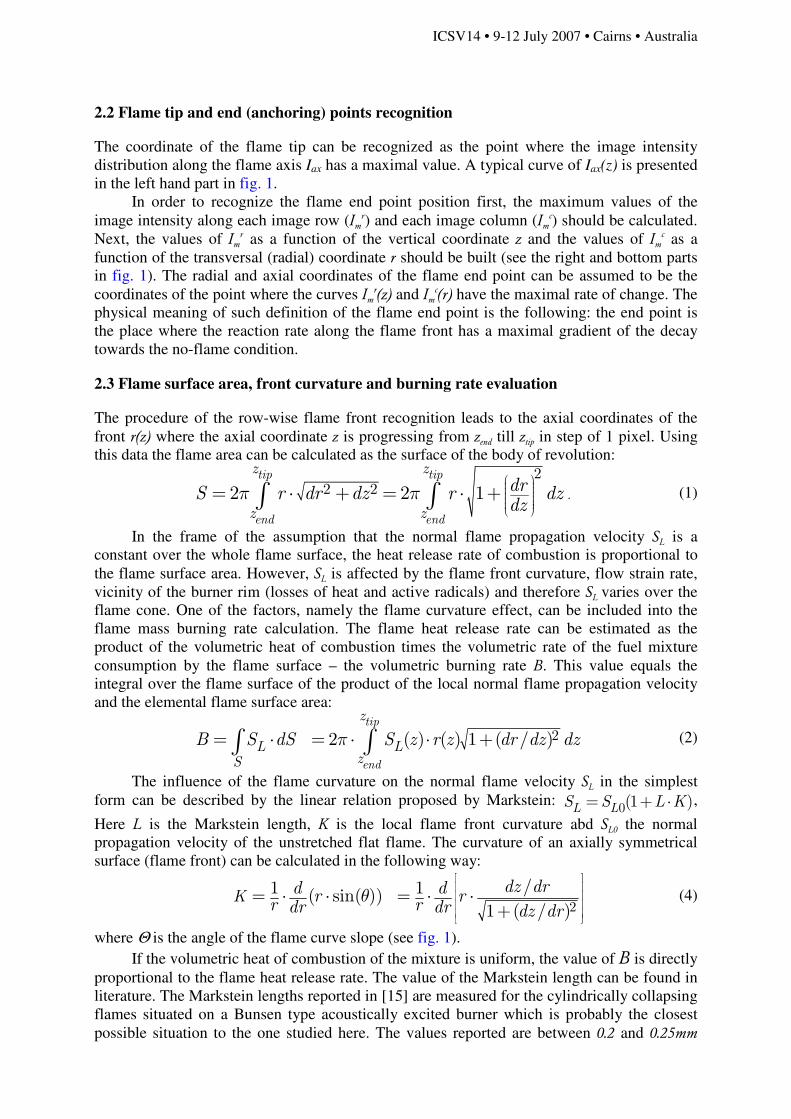
2.2 Flame tip and end (anchoring) points recognition
The coordinate of the flame tip can be recognized as the point where the image intensity
distribution along the flame axis Iax has a maximal value. A typical curve of Iax(z) is presented
in the left hand part in fig. 1.
In order to recognize the flame end point position first, the maximum values of the
image intensity along each image row (Imr) and each image column (Im
c) should be calculated.
Next, the values of Imr as a function of the vertical coordinate z and the values of Im
c as a
function of the transversal (radial) coordinate r should be built (see the right and bottom parts
in fig. 1). The radial and axial coordinates of the flame end point can be assumed to be the
coordinates of the point where the curves Imr(z) and Im
c(r) have the maximal rate of change. The
physical meaning of such definition of the flame end point is the following: the end point is
the place where the reaction rate along the flame front has a maximal gradient of the decay
towards the no-flame condition.
2.3 Flame surface area, front curvature and burning rate evaluation
The procedure of the row-wise flame front recognition leads to the axial coordinates of the
front r(z) where the axial coordinate z is progressing from zend till ztip in step of 1 pixel. Using
this data the flame area can be calculated as the surface of the body of revolution:
.
22 22 2 1
tip tip
end end
z z
z z
drS r dr dz r dzdz
π π
= ⋅ + = ⋅ +∫ ∫ (1)
In the frame of the assumption that the normal flame propagation velocity SL is a
constant over the whole flame surface, the heat release rate of combustion is proportional to
the flame surface area. However, SL is affected by the flame front curvature, flow strain rate,
vicinity of the burner rim (losses of heat and active radicals) and therefore SL varies over the
flame cone. One of the factors, namely the flame curvature effect, can be included into the
flame mass burning rate calculation. The flame heat release rate can be estimated as the
product of the volumetric heat of combustion times the volumetric rate of the fuel mixture
consumption by the flame surface – the volumetric burning rate B. This value equals the
integral over the flame surface of the product of the local normal flame propagation velocity
and the elemental flame surface area:
22 ( ) ( ) 1 ( / )tip
end
z
L LzS
B S dS S z r z dr dz dzπ= ⋅ = ⋅ ⋅ +∫ ∫ (2)
The influence of the flame curvature on the normal flame velocity SL in the simplest
form can be described by the linear relation proposed by Markstein: 0(1 )L LS S L K= + ⋅ ,
Here L is the Markstein length, K is the local flame front curvature abd SL0 the normal
propagation velocity of the unstretched flat flame. The curvature of an axially symmetrical
surface (flame front) can be calculated in the following way:
2
/1 1( sin( ))1 ( / )
Kdz drd dr r
r rdr dr dz drθ
= ⋅ ⋅ = ⋅ ⋅+
(4)
where Θ is the angle of the flame curve slope (see fig. 1).
If the volumetric heat of combustion of the mixture is uniform, the value of B is directly
proportional to the flame heat release rate. The value of the Markstein length can be found in
literature. The Markstein lengths reported in [15] are measured for the cylindrically collapsing
flames situated on a Bunsen type acoustically excited burner which is probably the closest
possible situation to the one studied here. The values reported are between 0.2 and 0.25mm

ICSV14 • 9-12 July 2007 • Cairns • Australia
and weakly depend on the mixture equivalence ratio. In the same article it is shown that in the
flame configuration similar to the one studied here the effect of flow strain rate on the normal
flame velocity SL is minor and can be neglected.
To study the correlation between the flame surface area (burning rate) and the flame
heat release rate (OH*) oscillation, synchronised flame visualization and OH* radiation
measurement was conducted using a photomultiplier equipped with appropriate UV filter. The
flow velocity oscillation was measured via a hot-wire anemometer probe placed upstream of
the flame and close to the burner rim. Further details can be found in [16].
3. OSCILLATING FLAME KINEMATICS
3.1 The flame end and tip points motion
In order to give an estimate how the excited flame cone looks like, several instantaneous
photos with arbitrary oscillation phase are presented in fig. 2. The relatively low amplitude of
the flow velocity excitation provides no cusps formation. The flame wrinkling is smooth and
close to sinusoidal.
To get more insight in the flame front kinematics the flame end point motions should be
first resolved. The flame end point recognition procedure described above delivers the radial
(rend) and axial (zend) coordinates of the end point. The oscillation phase resolved curves r(φ) and z(φ) typically have a close to harmonic form of the excitation frequency – see fig.3a.
Accordingly in the (r, z) plane, the perturbed flame end point path is an elliptical curve – see
fig.3b. The ellipse is elongated in the burner radial direction and slightly tilted (the amplitude
of rend is typically 2-3 times larger than the amplitude of zend). Figure 4 presents the frequency dependency of the rend , zend and ztip amplitudes. These
magnitudes are restored as the amplitudes of fitting the phase resolved measurements with a
harmonic function. Both rend and zend initially grow with the frequency, reach some maximum
and next decay smoothly.
In some frequency ranges the flame tip time evolution can be nonlinear (non-harmonic),
even in the case of the moderate amplitude of perturbation. For example, in fig. 3a the flame
tip moves smoothly up and sharply down. The amplitude of the flame tip oscillation as a
function of the excitation frequency has the distinct maximum –see fig 4.The tip motion
nonlinearity is especially pronounced in the frequency range around this maximum. Together
with the flame form disturbance propagation velocity (see below) this frequency corresponds
to a wavelength approximately equal to the flame height.
Figure 3. (a) Phase resolved disturbance of the flame end point radial and axial position as well as
flame tip perturbation. (b) Flame end point path; the ellipse represents the path after the sinusoidal
fitting of the phase resolved rend and zend. The flame is situated on the burner with flat velocity profile,
V0=100cm/s, Φ=1.2. Excitation frequency is 190Hz, amplitude is 20cm/s.

ICSV14 • 9-12 July 2007 • Cairns • Australia
3.2 Phase resolved flame form motion
To analyse the flame form disturbance kinematics, the front position should be recognised and
the deviation between the phase resolved front position and the one averaged over the
oscillation cycle should be calculated. Figure 5 presents an example of such calculation.
The disturbances propagation velocity can be calculated either as the distance between
two specific points (for instance the zero crossing points) of the two curves with a known time
interval in between or as the curve wavelength which, together with a known excitation
frequency, yields the propagation velocity. During disturbance propagation the wavelength
slightly changes (becomes ~10-20% shorter). However, the mean propagation velocity can be
estimated. The curve in fig 5 is fitted by a harmonic function and the mean wavelength λ
gives the propagation rate Vi=λf . The error of this estimation is at least not less than the drift
of the wavelength, namely ~15%.
The measurement of the disturbance propagation rate (projection of this velocity on the
vertical axis) shows that in the range [100-250Hz] the velocity is independent of the
frequency (in the frame of the estimation inaccuracy) and approximately 1.3 times larger that
the bulk gas velocity of the jet.
3.3 Relation between the flame surface area and heat release rate oscillation
Two important aspects of the flame area measurement should be mentioned. First of all, the
accurate recognition of the flame end point is crucially important for the correct examination
of the flame surface area kinematics. The procedures like to truncate the flame cone at some
Figure 4. Frequency dependence of the flame tip and end point radial and axial disturbance.
The flame is situated on the burner with flat velocity profile, V0=100cm/s, Φ=1.2. Velocity excitation
amplitude is ~20cm/s.
Figure 5. Instantaneous flame front radial displacements over
the relative height above the burner rim (H is the stationary
flame height). The phase interval between two lines is 90 degrees. The flame is situated on the burner with flat velocity
profile, V0=100cm/s, Φ=1.2. Excitation frequency is 210Hz.
Figure 6. Phase resolved oscillation of
flow velocity (1), flame heat release
rate /OH* – (2); flame surface area (3);
flame tip point (4). The same flame as
in fig. 5; excitation frequency 150Hz.

ICSV14 • 9-12 July 2007 • Cairns • Australia
level above the burner, or to extrapolate the front to the level of the burner rim lead to an
unacceptable error of measurement of the flame area temporal evolution.
The second aspect is related to the limitation of the measurement accuracy. The
estimation of the relative amplitude of the flame area oscillation gives a typical value in
between 0.7 and 2 percents from the mean value. It means that the relative accuracy of the
flame front surface area measurement should not be worse than 0.1-0.2% which is a
challenging task. This explains why the results presented are very noise sensitive.
Flame surface area and heat release rate correlation
Fig. 6 presents an example of the simultaneous measurement of the oscillation of several
flame kinematics and dynamics parameters. The close correlation of the flame area (S`) and
heat release rate (Q`) is evident. The frequency dependence of this correlation is presented in
fig. 7 where the ratio of the area oscillation amplitude to the amplitude of OH* signal and the
phase delay between these quantities are drawn versus the frequency. The measurement
inaccuracy is significant, however, the data points are randomly scattered around 1 and there
is no evident trend of the amplitude ratio.
The phase difference between Q`(t) and S`(t) as the function of frequency is also
randomly scattered around zero. Some remarkable phase difference can be measured in the
frequency range where the flame surface area response has a minimum (around 120Hz). This
frequency range is especially difficult for a precise measurement and inaccuracy can be
significant. However, the measured phase difference hardly exceeds 60 degrees.
Figure 7. (a) - Ratio of the amplitudes of the flame heat release rate and surface area (squares) or flame
burning rate (circles). (b) - Phase difference between the heat release rate and surface area or burning
rate oscillation.
Flame curvature effect
The flame front curvature affects the flame surface kinematics in two ways [13]. On one hand
because of the normal flame propagation velocity dependence on the front curvature the flame
wrinkles should smooth out. On the other hand the flame heat release rate is sensitive to the
normal flame propagation speed.
The last effect can be examined via a comparison of the heat release rate correlation
with the flame area (which is equivalent to the assumption SL=const) and with the flame
burning rate (surface integral of the curvature dependent SL). The results presented in fig. 7
signify that this effect seems to have a weak impact. Only for an excitation frequency range
(in fig. 7 this range is around f~120Hz) when the part of the flame close to the tip oscillates
with maximal amplitude the incorporation of the curvature dependence into SL slightly
improves the correlation between the burning rate and measured heat release rate.
The influence of the disturbance smoothing can’t be evaluated certainly on the basis of a
flame kinematics experiment because the disturbance kinematics is also conditioned by the
fresh gas flow pattern.

ICSV14 • 9-12 July 2007 • Cairns • Australia
4. CONCLUSIONS
The results of this experimental assessment of the assumptions routinely used in several
theoretical analyses of the perturbed flame indicate that:
- the flame anchoring point is not motionless. The flame end point moves predominantly in
the radial direction and the magnitude of the flame foot motion is frequency dependent.
- the oscillation of the flame surface area correlates (is in-phase) with the heat release rate.
The results reported in [10] are probably affected by the difficulties of the correct recognition
of the flame end point.
- the assumption of a constant flame propagation rate does not lead to significant deviation of
the flame heat release rate associated with the flame area in comparison with the burning rate
calculation where the curvature effect is included in SL.
Experiments confirm some of the theoretical results about the flame cone kinematics:
- the flame front radial displacement has a shape of a travelling wave which originates in the
flame base zone and propagates along the flame cone towards the flame tip with a velocity
somewhat larger than the mean flow velocity.
REFERENCES
1. Fleifil, M., et al., Response of a laminar premixed flame to flow oscillations: A kinematic model and
thermoacoustic instability results Combustion and Flame, 1996. 106(4): p. 487-510.
2. Schuller, T., et al., Modeling tools for the prediction of premixed flame transfer functions. Proc.
Combust. Inst., 2002. 29: p. 107-113.
3. Schuller, T., D. Durox, and S. Candel, A unified model for the prediction of laminar flame transfer
functions: comparisons between conical and V-flame dynamics Combustion and Flame, 2003. 134(1-
2): p. 21-34.
4. Lee, D.H. and T.C. Lieuwen, Premixed Flame Kinematics in a Longitudinal Acoustic Field. Journal of
Propulsion and Power, 2003. 19(5): p. 837-846.
5. Ducruix, S., D. Durox, and S. Candel, Theoretical and experimental determination of the transfer
function of laminar premixed flame. Processing of Combustion Institute, 2000. 28: p. 765 - 773.
6. Markstein, G.H., Interaction of Flame Propagation and Flow Disturbances. Proc. Combust. Inst,
1948(3): p. 162-167.
7. Blackshear, P.L.J., Driving Standing Waves by Heat Addition Proc. Combust. Inst., 1953(4): p. 553-
566.
8. Candel, S., Combustion Dynamics and control: progress and challenges. Proc. Combust. Inst., 2002.
29: p. 1-28.
9. Lieuwen, T.C., Modeling premixed combustion-acoustic wave interaction: A review. Journal of
Propulsion and Power, 2003. 19(5): p. 765-781.
10. Ferguson, D., et al. Effect of surface area variation on heat release rates in premixed flames. in 2-nd
Join Meeting of the U.S. Sections of the Combustion Institute. 2001. Oakland, CA USA.
11. Balachandran, R., et al., Experimental investigation of the nonlinear response of turbulent premixed
flames to imposed inlet velocity oscillations Combustion and Flame, 2006. 143(1-2): p. 37-55.
12. Boyer, L. and J. Quinard, On the dynamics of anchored flames. Combustion and Flame, 1990. 82(1): p.
51-65.
13. Preetham, T.S. Kumar, and T.C. Lieuwen. Response of Premixed Flames to Flow Oscillation: Unstaedy
Curvature Effects. in 44-th AIAA Aerospace Sciences Meeting and Exhibit. 2006. Reno, Navada: AIAA
2006-0960.
14. Sugimoto, T. and Y. Matsui, An experimental study of the dynamic behavior of premixed laminar
flames. Proc. Combust. Inst., 1982. 19: p. 245-250.
15. Durox, D., S. Ducruix, and S. Candel, Experiments on collapsing cylindrical flames. Combustion and
Flame, 2001. 125(1-2): p. 982-1000.
16. Kornilov, V.N., Experimental Research of Acoustically Perturbed Bunsen Flames, PhD thesis, 2006,
TU/e: Eindhoven. p. 134.
Related Documents