Experimental performance evaluation and comparative analyses of heat pipe and direct flow augmented solar collectors Dan Nchelatebe Nkwetta a, * , Mervyn Smyth b , Fariborz Haghighat a , Aggelos Zacharopoulos b , Trevor Hyde b a Department of Building, Civil and Environmental Engineering, Concordia University, Montreal, Quebec H3G 1M8, Canada b Centre for Sustainable Technologies, School of the Built Environment, Faculty of Arts, Design and Built Environment, University of Ulster at Jordanstown, UK highlights Performance evaluation of internal concentrator augmented solar collectors is presented. Two different heat extraction methods were used and experimental collection efficiency provided. To reduce heat loss, augmented concentrators were evacuated. Heat pipe augmented concentrators proves better than to direct flow augmented concentrators. article info Article history: Received 15 February 2013 Accepted 30 June 2013 Available online 11 July 2013 Keywords: Heat pipe augmented collectors Direct flow augmented collectors Internal concentrators Collection efficiency Heat loss coefficient and temperature differential abstract Experimental performance evaluation and comparative analyses of two different types of internal concentrator augmented solar collectors; the evacuated tube heat pipe solar collector array with either an evacuated or non-evacuated direct flow or heat pipe internal concentrator augmented collectors based on heat extraction methods are presented in this paper. To effectively analysis and compare these systems under similar operating conditions, experimental results are presented in the form of temper- ature response (inlet and outlet temperature increase, outlet and inlet temperature differential, mean temperature differential at the start and end of the experimental test periods), heat flow rates and collection efficiency plotted against experimental test time. This analytical method shows the merits and demerits of each solar collector operating under variable conditions and indicates the best application area for each system. The evacuated and non-evacuated heat pipe augmented concentrators proved to be better options for medium temperature applications due to higher temperature response, lower heat losses and higher collection efficiencies. Ó 2013 Elsevier Ltd. All rights reserved. 1. Introduction Non-concentrated evacuated tube heat pipe solar collectors have been reported to show higher fluid temperatures with improved thermal performance (higher efficiency) only at low temperature range due to better value of zero loss efficiency but suffer higher heat losses at medium to higher temperature range which reduces their efficiency compared to concentrated evacuated tube heat pipe solar collectors [10]. External and single concen- trating collectors are not only uneconomical due to the large sizes of the reflectors and collectors but are also less efficient especially at medium to higher temperature range due to greater reflector loss compared to internal concentrating augmented solar collectors [5,6,12]. Liquid solar collectors for domestic heating and cooling appli- cations commonly in used are the flat plate and evacuated tube solar collectors. Evacuated tube solar collectors are either concen- trated or non-concentrated and involve either the use of a heat pipe or direct flow absorber to extract heat. The Commission of Euro- pean Communities (2006) [1] reported that world energy demand and CO 2 emissions are expected to rise by some 60% by 2030 and EU energy import dependency is forecasted to increase to about 70% by 2030. Energy demand for cooling is expected to increase rapidly over the century due to global warming with 1.1 Ce6.4 C rise in surface temperatures if emissions are not curbed [2]. As such, solar air conditioning systems will play a significant role in meeting the demand since there is good load matching of the available peak solar radiation with maximum cooling load. * Corresponding author. Tel.: þ1 514 848 2424x7016. E-mail address: [email protected] (D.N. Nkwetta). Contents lists available at SciVerse ScienceDirect Applied Thermal Engineering journal homepage: www.elsevier.com/locate/apthermeng 1359-4311/$ e see front matter Ó 2013 Elsevier Ltd. All rights reserved. http://dx.doi.org/10.1016/j.applthermaleng.2013.06.059 Applied Thermal Engineering 60 (2013) 225e233

Welcome message from author
This document is posted to help you gain knowledge. Please leave a comment to let me know what you think about it! Share it to your friends and learn new things together.
Transcript
at SciVerse ScienceDirect
Applied Thermal Engineering 60 (2013) 225e233
Contents lists available
Applied Thermal Engineering
journal homepage: www.elsevier .com/locate/apthermeng
Experimental performance evaluation and comparative analysesof heat pipe and direct flow augmented solar collectors
Dan Nchelatebe Nkwetta a,*, Mervyn Smyth b, Fariborz Haghighat a,Aggelos Zacharopoulos b, Trevor Hyde b
aDepartment of Building, Civil and Environmental Engineering, Concordia University, Montreal, Quebec H3G 1M8, CanadabCentre for Sustainable Technologies, School of the Built Environment, Faculty of Arts, Design and Built Environment, University of Ulster at Jordanstown, UK
h i g h l i g h t s
� Performance evaluation of internal concentrator augmented solar collectors is presented.� Two different heat extraction methods were used and experimental collection efficiency provided.� To reduce heat loss, augmented concentrators were evacuated.� Heat pipe augmented concentrators proves better than to direct flow augmented concentrators.
a r t i c l e i n f o
Article history:Received 15 February 2013Accepted 30 June 2013Available online 11 July 2013
Keywords:Heat pipe augmented collectorsDirect flow augmented collectorsInternal concentratorsCollection efficiencyHeat loss coefficient and temperaturedifferential
* Corresponding author. Tel.: þ1 514 848 2424x701E-mail address: [email protected] (D.N. Nkw
1359-4311/$ e see front matter � 2013 Elsevier Ltd.http://dx.doi.org/10.1016/j.applthermaleng.2013.06.05
a b s t r a c t
Experimental performance evaluation and comparative analyses of two different types of internalconcentrator augmented solar collectors; the evacuated tube heat pipe solar collector array with eitheran evacuated or non-evacuated direct flow or heat pipe internal concentrator augmented collectorsbased on heat extraction methods are presented in this paper. To effectively analysis and compare thesesystems under similar operating conditions, experimental results are presented in the form of temper-ature response (inlet and outlet temperature increase, outlet and inlet temperature differential, meantemperature differential at the start and end of the experimental test periods), heat flow rates andcollection efficiency plotted against experimental test time. This analytical method shows the merits anddemerits of each solar collector operating under variable conditions and indicates the best applicationarea for each system. The evacuated and non-evacuated heat pipe augmented concentrators proved to bebetter options for medium temperature applications due to higher temperature response, lower heatlosses and higher collection efficiencies.
� 2013 Elsevier Ltd. All rights reserved.
1. Introduction
Non-concentrated evacuated tube heat pipe solar collectorshave been reported to show higher fluid temperatures withimproved thermal performance (higher efficiency) only at lowtemperature range due to better value of zero loss efficiency butsuffer higher heat losses at medium to higher temperature rangewhich reduces their efficiency compared to concentrated evacuatedtube heat pipe solar collectors [10]. External and single concen-trating collectors are not only uneconomical due to the large sizesof the reflectors and collectors but are also less efficient especiallyat medium to higher temperature range due to greater reflector loss
6.etta).
All rights reserved.9
compared to internal concentrating augmented solar collectors[5,6,12].
Liquid solar collectors for domestic heating and cooling appli-cations commonly in used are the flat plate and evacuated tubesolar collectors. Evacuated tube solar collectors are either concen-trated or non-concentrated and involve either the use of a heat pipeor direct flow absorber to extract heat. The Commission of Euro-pean Communities (2006) [1] reported that world energy demandand CO2 emissions are expected to rise by some 60% by 2030 and EUenergy import dependency is forecasted to increase to about 70% by2030. Energy demand for cooling is expected to increase rapidlyover the century due to global warming with 1.1 �Ce6.4 �C rise insurface temperatures if emissions are not curbed [2]. As such, solarair conditioning systems will play a significant role in meeting thedemand since there is good load matching of the available peaksolar radiation with maximum cooling load.
Nomenclature and abbreviations
Aap aperture area (m2)Qcollected thermal energy collected (MJ)Qincident incident solar radiation (W/m2)Gave average solar insolation (W/m2)_m mass flow rate (kg/s)Toutlet outlet water temperature (�C)Tinlet inlet water temperature (�C)Tave average water temperature (�C)cp specific heat constant of water (J/(kg K)DTinc outlet and inlet temperature increase (�C)hcollector collector efficiency (%)Tamb ambient temperature (�C)Tm mean fluid temperature (�C)Tinc mean fluid temperature differential at the end and
start of the test period (�C)Tm,end mean fluid temperature at the end of the test period
(�C)Tm,start mean fluid temperature at the start of the test
period (�C)ASHRAE American Society of Heating and Refrigeration and
Air Conditioning EngineersCPC compound parabolic concentratorIPCC Intergovernmental Panel on Climate Change
D.N. Nkwetta et al. / Applied Thermal Engineering 60 (2013) 225e233226
However, solar air conditioning systems are in need of a mini-mum generator input temperature of 75e90 �C for a single-effectabsorption refrigeration system and 90e120 �C for a double-effect absorption refrigeration system [3,4], needing more effi-cient collecting systems with minimal heat losses. Evacuated tubesolar collectors have low convectional and conduction heat lossescompared to convectional flat plate collectors due to the vacuumenvelope around the absorber surface and a combination of inter-nal concentrators and evacuated tube solar collectors known asconcentrator augmented solar collectors have the potential tofurther reduce these losses. The choice of an optimal collector de-pends on the temperature requirement of the specific applicationand on the climatic conditions where the solar system is installed.The solar systems have to be optimized to provide cost effectiveenergy savings as well as a reduce payback period and thusimperative to choose, design and experimentally characterized theright collectors for the right applications.
Evacuated tube heat pipe solar collector operates by transferringthermal energy from the absorber fins to the heat transfer fluid(HTF) with only a small temperature differential existing betweenthe fin absorber and the condenser with configuration acting as athermal diode (preventing reverse flow of heat) during non-operational periods [5e7]. Freezing of the heat pipe is unusualand is generally not destructive. The heat pipe system operatesindependently of gravity, is silent with no moving parts and thusneeds minimal servicing [8]. The collectors were designed at theUniversity of Ulster, UK such that the HTF in the internal compoundparabolic concentrator with direct flow absorber (ICPC-DFA) entersthe solar collector via the inner tube and flows down into the baseof the larger outer tube through the opening at the base of the innertube [9e13]. The HFT then flows upwards in direct contact with theouter-coated absorbing surface exposed to solar radiation, thustransferring the solar gain to the HTF. With the internal compoundparabolic concentrator with heat pipe absorber (ICPC-HPA), thecoated heat pipe attached to the back of the absorber plate con-taining a small volume of working HTF (evaporator) causes thetemperature of the HTF in the heat pipe to rise once exposed to
incident solar radiation. The rising temperature results in the HTFof the heat pipe undergoing an evaporatingecondensing cycletransferring heat to the condenser located in the manifold,condensing and releasing the latent heat to heat up the HTF (water)as it flow through the manifold. Experimental demonstrationproved that increasing the inlet fluid temperature of a solar airconditioning system increases the coefficient of performance (COP)[4], necessitating the use of internal concentrating augmented solarcollectors compared to external concentrating solar collectors withadditional reflector sizes with greater reflector losses and cost[9,12]. The use of internal concentrating augmented solar collectorswith either a heat pipe or direct flow absorber is advantageouscompared to external concentrating augmented solar collectorswith reflector fabrication and size reduction, higher operatingtemperature differential due to reduced reflector losses with sub-stantial improvement in thermal performance existing at mediumto high temperature range and huge economic potential [9e13].This paper looked at the performance of a solar collector composedof an array of three evacuated heat pipes and an ICPC-HP (heatpipe) or an ICPC-DF (direct flow) tube under control laboratoryconditions.
These collectors are new concepts introduced by the authors tolook at the possibilities of combining both evacuated tube heatpipe solar collector and concentrator to reduce experimentalheating time needed to attained medium temperatures, size ofsolar collector array and associated cost. Furthermore, the potentialto reduce manifold losses resulting from reduction in number ofevacuated tube heat pipe and size of manifold while attaininghigher temperatures over shorter time scale especially at plus orminus 2 h of solar noon is investigated and critical for solar coolingneeds occurring during that time scale. The effect of evacuatingheat pipe and direct flow concentrator augmented solar collectorswas investigated due to their potential to further reduce heatlosses. A comparative analysis showed 1.39 W m�2 K�1 (36.01%)and 2.11 W m�2 K�1 (35.17%) lower heat loss coefficients realisedby the EICPC-HPA and the NEICPC-HPA solar collectors, comparedto the EICPC-DFA and the NEICPC-DFA solar collectors, respectively.In addition, heat pipe augmented solar collectors had better ther-mal response resulting in higher temperatures with larger tem-perature differential compared to direct flow augmented solarcollectors.
2. Experimental design, fabrication and assembly
The evacuated tube with an internal compound parabolicconcentrating (EICPC) reflector fabricated to be used as a concen-trator augmented collector utilised two different absorber modes toextract heat from the cusp CPC profile; the evacuated internal CPCwith heat pipe absorber (EICPC-HP) and evacuated internal CPCwith direct flow absorber (EICPC-DF) collectors. The EICPC solarcollector design has an effective tubular absorber diameter of15 mm with an aperture width of 91 mm and total length of1500 mm. The EICPC solar collector was enclosed using a borosili-cate evacuated glass tube with 100 mm and 93mm outer and innerdiameter respectively and 3.5 mm wall thickness. The full EICPCsolar collector had an acceptance half-angle of 20� with a concen-tration ratio of 2.92. The cusp reflector profile was truncated to aconcentration ratio of 1.95 to permit enclosurewith the borosilicateevacuated glass tube.
The coordinates of the cusp reflector, the borosilicate glass tubeand the tubular absorber were generated via Tecplot and trans-ferred to an ‘AUTOCAD’ format to draw the profiles in a ‘dxf’ formatand the ‘AUTOCAD’ generated profile for the EICPC is illustrated inFig. 1. This enabled the structural profile to be machined in thelaboratory at the University of Ulster using a CNC machine to
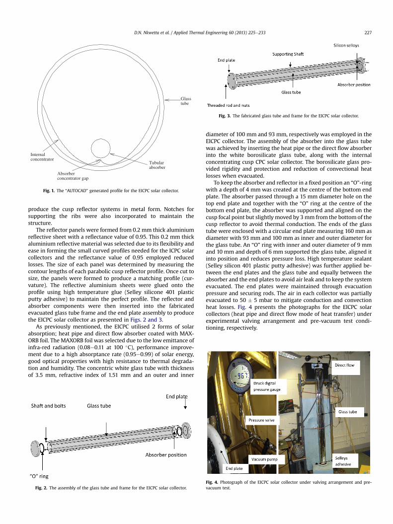
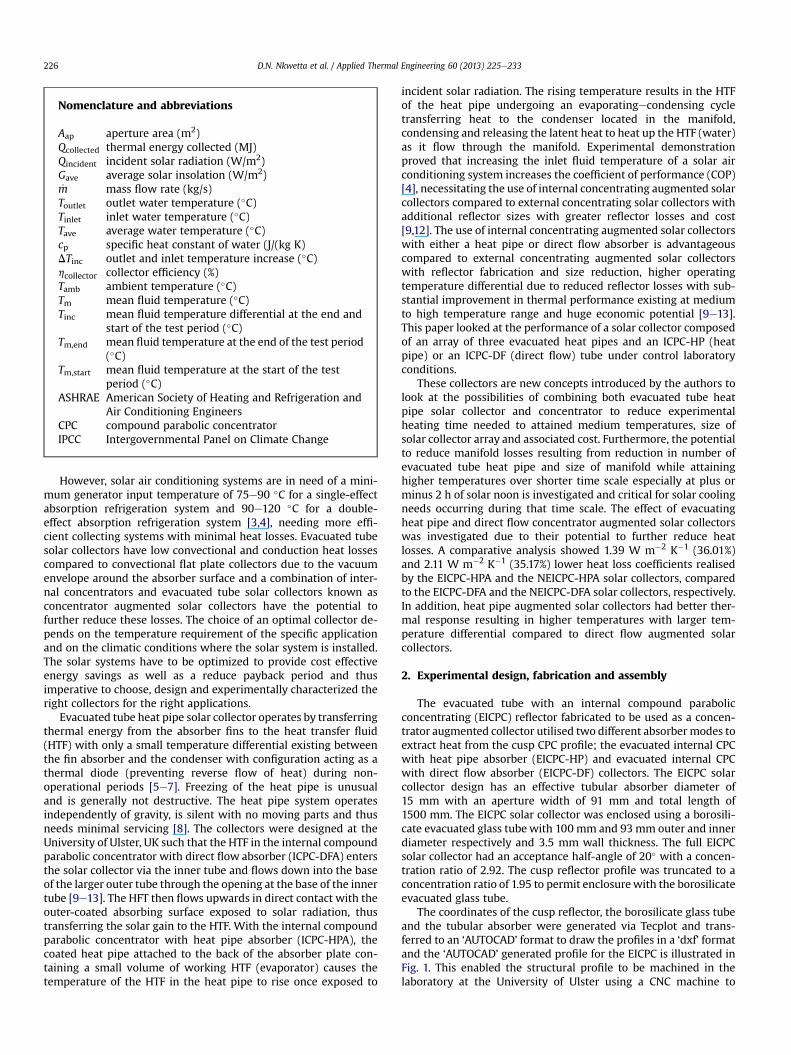
Fig. 3. The fabricated glass tube and frame for the EICPC solar collector.
Glasstube
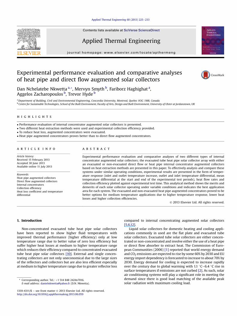
Internalconcentrator
Absorberconcentrator gap
Tubularabsorber
Fig. 1. The “AUTOCAD” generated profile for the EICPC solar collector.
D.N. Nkwetta et al. / Applied Thermal Engineering 60 (2013) 225e233 227
produce the cusp reflector systems in metal form. Notches forsupporting the ribs were also incorporated to maintain thestructure.
The reflector panels were formed from 0.2 mm thick aluminiumreflective sheet with a reflectance value of 0.95. This 0.2 mm thickaluminium reflective material was selected due to its flexibility andease in forming the small curved profiles needed for the ICPC solarcollectors and the reflectance value of 0.95 employed reducedlosses. The size of each panel was determined by measuring thecontour lengths of each parabolic cusp reflector profile. Once cut tosize, the panels were formed to produce a matching profile (cur-vature). The reflective aluminium sheets were glued onto theprofile using high temperature glue (Selley silicone 401 plasticputty adhesive) to maintain the perfect profile. The reflector andabsorber components were then inserted into the fabricatedevacuated glass tube frame and the end plate assembly to producethe EICPC solar collector as presented in Figs. 2 and 3.
As previously mentioned, the EICPC utilised 2 forms of solarabsorption; heat pipe and direct flow absorber coated with MAX-ORB foil. The MAXORB foil was selected due to the low emittance ofinfra-red radiation (0.08e0.11 at 100 �C), performance improve-ment due to a high absorptance rate (0.95e0.99) of solar energy,good optical properties with high resistance to thermal degrada-tion and humidity. The concentric white glass tube with thicknessof 3.5 mm, refractive index of 1.51 mm and an outer and inner
Fig. 2. The assembly of the glass tube and frame for the EICPC solar collector.
diameter of 100 mm and 93 mm, respectively was employed in theEICPC collector. The assembly of the absorber into the glass tubewas achieved by inserting the heat pipe or the direct flow absorberinto the white borosilicate glass tube, along with the internalconcentrating cusp CPC solar collector. The borosilicate glass pro-vided rigidity and protection and reduction of convectional heatlosses when evacuated.
To keep the absorber and reflector in a fixed position an “O”-ringwith a depth of 4 mm was created at the centre of the bottom endplate. The absorber passed through a 15 mm diameter hole on thetop end plate and together with the “O” ring at the centre of thebottom end plate, the absorber was supported and aligned on thecusp focal point but slightly moved by 3mm from the bottom of thecusp reflector to avoid thermal conduction. The ends of the glasstube were enclosed with a circular end plate measuring 160 mm asdiameter with 93 mm and 100 mm as inner and outer diameter forthe glass tube. An “O” ring with inner and outer diameter of 9 mmand 10 mm and depth of 6 mm supported the glass tube, aligned itinto position and reduces pressure loss. High temperature sealant(Selley silicon 401 plastic putty adhesive) was further applied be-tween the end plates and the glass tube and equally between theabsorber and the end plates to avoid air leak and to keep the systemevacuated. The end plates were maintained through evacuationpressure and securing rods. The air in each collector was partiallyevacuated to 50 � 5 mbar to mitigate conduction and convectionheat losses. Fig. 4 presents the photographs for the EICPC solarcollectors (heat pipe and direct flow mode of heat transfer) underexperimental valving arrangement and pre-vacuum test condi-tioning, respectively.
Fig. 4. Photograph of the EICPC solar collector under valving arrangement and pre-vacuum test.
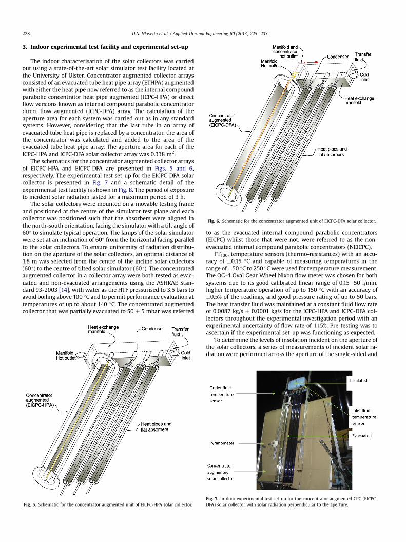
Fig. 6. Schematic for the concentrator augmented unit of EICPC-DFA solar collector.
D.N. Nkwetta et al. / Applied Thermal Engineering 60 (2013) 225e233228
3. Indoor experimental test facility and experimental set-up
The indoor characterisation of the solar collectors was carriedout using a state-of-the-art solar simulator test facility located atthe University of Ulster. Concentrator augmented collector arraysconsisted of an evacuated tube heat pipe array (ETHPA) augmentedwith either the heat pipe now referred to as the internal compoundparabolic concentrator heat pipe augmented (ICPC-HPA) or directflow versions known as internal compound parabolic concentratordirect flow augmented (ICPC-DFA) array. The calculation of theaperture area for each system was carried out as in any standardsystems. However, considering that the last tube in an array ofevacuated tube heat pipe is replaced by a concentrator, the area ofthe concentrator was calculated and added to the area of theevacuated tube heat pipe array. The aperture area for each of theICPC-HPA and ICPC-DFA solar collector array was 0.338 m2.
The schematics for the concentrator augmented collector arraysof EICPC-HPA and EICPC-DFA are presented in Figs. 5 and 6,respectively. The experimental test set-up for the EICPC-DFA solarcollector is presented in Fig. 7 and a schematic detail of theexperimental test facility is shown in Fig. 8. The period of exposureto incident solar radiation lasted for a maximum period of 3 h.
The solar collectors were mounted on a movable testing frameand positioned at the centre of the simulator test plane and eachcollector was positioned such that the absorbers were aligned inthe north-south orientation, facing the simulator with a tilt angle of60� to simulate typical operation. The lamps of the solar simulatorwere set at an inclination of 60� from the horizontal facing parallelto the solar collectors. To ensure uniformity of radiation distribu-tion on the aperture of the solar collectors, an optimal distance of1.8 m was selected from the centre of the incline solar collectors(60�) to the centre of tilted solar simulator (60�). The concentratedaugmented collector in a collector array were both tested as evac-uated and non-evacuated arrangements using the ASHRAE Stan-dard 93-2003 [14], with water as the HTF pressurised to 3.5 bars toavoid boiling above 100 �C and to permit performance evaluation attemperatures of up to about 140 �C. The concentrated augmentedcollector that was partially evacuated to 50 � 5 mbar was referred
Fig. 5. Schematic for the concentrator augmented unit of EICPC-HPA solar collector.
to as the evacuated internal compound parabolic concentrators(EICPC) whilst those that were not, were referred to as the non-evacuated internal compound parabolic concentrators (NEICPC).
PT100, temperature sensors (thermo-resistances) with an accu-racy of �0.15 �C and capable of measuring temperatures in therange of�50 �C to 250 �Cwere used for temperature measurement.The OG-4 Oval Gear Wheel Nixon flow meter was chosen for bothsystems due to its good calibrated linear range of 0.15e50 l/min,higher temperature operation of up to 150 �C with an accuracy of�0.5% of the readings, and good pressure rating of up to 50 bars.The heat transfer fluid was maintained at a constant fluid flow rateof 0.0087 kg/s � 0.0001 kg/s for the ICPC-HPA and ICPC-DFA col-lectors throughout the experimental investigation period with anexperimental uncertainty of flow rate of 1.15%. Pre-testing was toascertain if the experimental set-up was functioning as expected.
To determine the levels of insolation incident on the aperture ofthe solar collectors, a series of measurements of incident solar ra-diationwere performed across the aperture of the single-sided and
Fig. 7. In-door experimental test set-up for the concentrator augmented CPC (EICPC-DFA) solar collector with solar radiation perpendicular to the aperture.
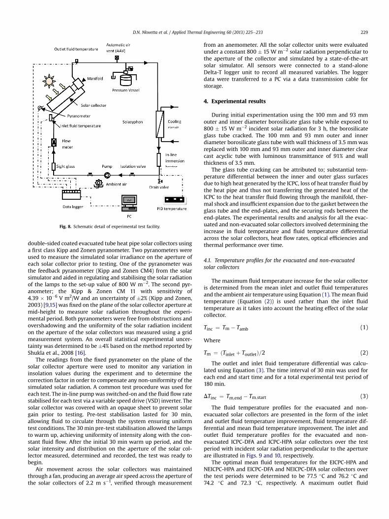
Fig. 8. Schematic detail of experimental test facility.
D.N. Nkwetta et al. / Applied Thermal Engineering 60 (2013) 225e233 229
double-sided coated evacuated tube heat pipe solar collectors usinga first class Kipp and Zonen pyranometer. Two pyranometers wereused to measure the simulated solar irradiance on the aperture ofeach solar collector prior to testing. One of the pyranometer wasthe feedback pyranometer (Kipp and Zonen CM4) from the solarsimulator and aided in regulating and stabilising the solar radiationof the lamps to the set-up value of 800 W m�2. The second pyr-anometer; the Kipp & Zonen CM 11 with sensitivity of4.39 � 10�6 V m2/W and an uncertainty of �2% (Kipp and Zonen,2003) [9,15] was fixed on the plane of the solar collector aperture atmid-height to measure solar radiation throughout the experi-mental period. Both pyranometers were free from obstructions andovershadowing and the uniformity of the solar radiation incidenton the aperture of the solar collectors was measured using a gridmeasurement system. An overall statistical experimental uncer-tainty was determined to be �4% based on the method reported byShukla et al., 2008 [16].
The readings from the fixed pyranometer on the plane of thesolar collector aperture were used to monitor any variation ininsolation values during the experiment and to determine thecorrection factor in order to compensate any non-uniformity of thesimulated solar radiation. A common test procedure was used foreach test. The in-line pumpwas switched-on and the fluid flow ratestabilised for each test via a variable speed drive (VSD) inverter. Thesolar collector was covered with an opaque sheet to prevent solargain prior to testing. Pre-test stabilisation lasted for 30 min,allowing fluid to circulate through the system ensuring uniformtest conditions. The 30 min pre-test stabilisation allowed the lampsto warm up, achieving uniformity of intensity along with the con-stant fluid flow. After the initial 30 min warm up period, and thesolar intensity and distribution on the aperture of the solar col-lector measured, determined and recorded, the test was ready tobegin.
Air movement across the solar collectors was maintainedthrough a fan, producing an average air speed across the aperture ofthe solar collectors of 2.2 m s�1, verified through measurement
from an anemometer. All the solar collector units were evaluatedunder a constant 800 � 15 W m�2 solar radiation perpendicular tothe aperture of the collector and simulated by a state-of-the-artsolar simulator. All sensors were connected to a stand-aloneDelta-T logger unit to record all measured variables. The loggerdata were transferred to a PC via a data transmission cable forstorage.
4. Experimental results
During initial experimentation using the 100 mm and 93 mmouter and inner diameter borosilicate glass tube while exposed to800 � 15 W m�2 incident solar radiation for 3 h, the borosilicateglass tube cracked. The 100 mm and 93 mm outer and innerdiameter borosilicate glass tube with wall thickness of 3.5 mmwasreplaced with 100 mm and 93 mm outer and inner diameter clearcast acyclic tube with luminous transmittance of 91% and wallthickness of 3.5 mm.
The glass tube cracking can be attributed to; substantial tem-perature differential between the inner and outer glass surfacesdue to high heat generated by the ICPC, loss of heat transfer fluid bythe heat pipe and thus not transferring the generated heat of theICPC to the heat transfer fluid flowing through the manifold, ther-mal shock and insufficient expansion due to the gasket between theglass tube and the end-plates, and the securing rods between theend-plates. The experimental results and analysis for all the evac-uated and non-evacuated solar collectors involved determining theincrease in fluid temperature and fluid temperature differentialacross the solar collectors, heat flow rates, optical efficiencies andthermal performance over time.
4.1. Temperature profiles for the evacuated and non-evacuatedsolar collectors
The maximum fluid temperature increase for the solar collectoris determined from the mean inlet and outlet fluid temperaturesand the ambient air temperature using Equation (1). Themean fluidtemperature (Equation (2)) is used rather than the inlet fluidtemperature as it takes into account the heating effect of the solarcollector.
Tinc ¼ Tm � Tamb (1)
Where
Tm ¼ ðTinlet þ ToutletÞ=2 (2)
The outlet and inlet fluid temperature differential was calcu-lated using Equation (3). The time interval of 30 min was used foreach end and start time and for a total experimental test period of180 min.
DTinc ¼ Tm;end � Tm;start (3)
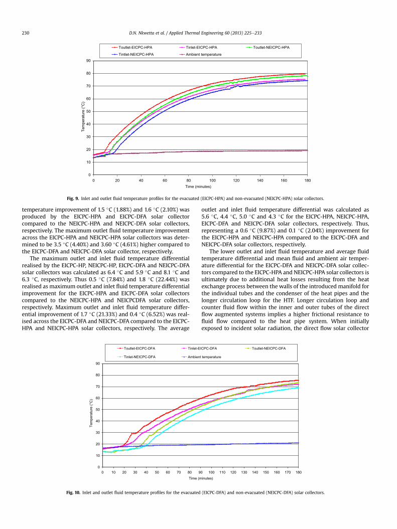
The fluid temperature profiles for the evacuated and non-evacuated solar collectors are presented in the form of the inletand outlet fluid temperature improvement, fluid temperature dif-ferential and mean fluid temperature improvement. The inlet andoutlet fluid temperature profiles for the evacuated and non-evacuated ICPC-DFA and ICPC-HPA solar collectors over the testperiod with incident solar radiation perpendicular to the apertureare illustrated in Figs. 9 and 10, respectively.
The optimal mean fluid temperatures for the EICPC-HPA andNEICPC-HPA and EICPC-DFA and NEICPC-DFA solar collectors overthe test periods were determined to be 77.5 �C and 76.2 �C and74.2 �C and 72.3 �C, respectively. A maximum outlet fluid
0
10
20
30
40
50
60
70
80
90
0 20 40 60 80 100 120 140 160 180Time (minutes)
Tem
pera
ture
(°C
)
Toutlet-EICPC-HPA Tinlet-EICPC-HPA Toutlet-NEICPC-HPA
Tintlet-NEICPC-HPA Ambient temperature
Fig. 9. Inlet and outlet fluid temperature profiles for the evacuated (EICPC-HPA) and non-evacuated (NEICPC-HPA) solar collectors.
D.N. Nkwetta et al. / Applied Thermal Engineering 60 (2013) 225e233230
temperature improvement of 1.5 �C (1.88%) and 1.6 �C (2.10%) wasproduced by the EICPC-HPA and EICPC-DFA solar collectorcompared to the NEICPC-HPA and NEICPC-DFA solar collectors,respectively. The maximum outlet fluid temperature improvementacross the EICPC-HPA and NEICPC-HPA solar collectors was deter-mined to be 3.5 �C (4.40%) and 3.60 �C (4.61%) higher compared tothe EICPC-DFA and NEICPC-DFA solar collector, respectively.
The maximum outlet and inlet fluid temperature differentialrealised by the EICPC-HP, NEICPC-HP, EICPC-DFA and NEICPC-DFAsolar collectors was calculated as 6.4 �C and 5.9 �C and 8.1 �C and6.3 �C, respectively. Thus 0.5 �C (7.84%) and 1.8 �C (22.44%) wasrealised as maximum outlet and inlet fluid temperature differentialimprovement for the EICPC-HPA and EICPC-DFA solar collectorscompared to the NEICPC-HPA and NEICPCDFA solar collectors,respectively. Maximum outlet and inlet fluid temperature differ-ential improvement of 1.7 �C (21.33%) and 0.4 �C (6.52%) was real-ised across the EICPC-DFA and NEICPC-DFA compared to the EICPC-HPA and NEICPC-HPA solar collectors, respectively. The average
0
10
20
30
40
50
60
70
80
90
0 10 20 30 40 50 60 70 80 9Time (m
Tem
pera
ture
(°C
)
Toutlet-EICPC-DFA Tinlet-E
Tinlet-NEICPC-DFA Ambien
Fig. 10. Inlet and outlet fluid temperature profiles for the evacuated
outlet and inlet fluid temperature differential was calculated as5.6 �C, 4.4 �C, 5.0 �C and 4.3 �C for the EICPC-HPA, NEICPC-HPA,EICPC-DFA and NEICPC-DFA solar collectors, respectively. Thus,representing a 0.6 �C (9.87%) and 0.1 �C (2.04%) improvement forthe EICPC-HPA and NEICPC-HPA compared to the EICPC-DFA andNEICPC-DFA solar collectors, respectively.
The lower outlet and inlet fluid temperature and average fluidtemperature differential and mean fluid and ambient air temper-ature differential for the EICPC-DFA and NEICPC-DFA solar collec-tors compared to the EICPC-HPA and NEICPC-HPA solar collectors isultimately due to additional heat losses resulting from the heatexchange process between the walls of the introduced manifold forthe individual tubes and the condenser of the heat pipes and thelonger circulation loop for the HTF. Longer circulation loop andcounter fluid flow within the inner and outer tubes of the directflow augmented systems implies a higher frictional resistance tofluid flow compared to the heat pipe system. When initiallyexposed to incident solar radiation, the direct flow solar collector
0 100 110 120 130 140 150 160 170 180inutes)
ICPC-DFA Toutlet-NEICPC-DFA
t temperature
(EICPC-DFA) and non-evacuated (NEICPC-DFA) solar collectors.

D.N. Nkwetta et al. / Applied Thermal Engineering 60 (2013) 225e233 231
units had amore rapid thermal response compared to the heat pipeunits, due to the thermal inertia of refrigerant in the heat pipe. Inthe heat pipe system, the liquid in the heat pipes is initially heated,then it evaporates and boils and transfers the heat to the HTF, thoseindirect transfer of heat and resultant lesser thermal responsewhereas the HTF in the direct flow system is directly heated onexposure to the incident solar radiation.
4.2. Heat flow rate for the evacuated and the non-evacuatedcollectors
The amount of simulated radiation incident on the aperture areaof all the solar collectors over each test period was calculated usingEquation (4). The heat flow rate involved calculating the energycollected using Equation (6), at 30 min time interval. The totalenergy collected involved summing-up the energy collected overthe entire experimental test period of 180 min at 30 min end andstart time interval. Fig. 11 show the heat flow rate for EICPCHPA,NEICPC-HPA, EICPC-DFA and NEICPC-DFA solar collectors. Table 1details the total energy collected for the EICPC-HPA, NEICPC-HPA,EICPCDFA and NEICPC-DFA solar collectors with the solar radiationperpendicular to aperture.
Qincident ¼ GaveAap (4)
Where
Gave ¼
0B@
Ztend
tstart
GðtÞdt
1CA
Dt(5)
Qcollected ¼ _mcpðToutlet � TinletÞ (6)
As expected, the optimal heat flow rate for all evacuated andnon-evacuated solar collectors were higher than the instantaneousheat flow rate at the end of the test period and the average dailyheat flow rates due to heat losses. The EICPC-HPA and NEICPC-HPAsolar collectors (Fig. 11) recorded a decreasing heat flow rateranging from 213.3 W to 166 W and 205.4 We124.1 W at the startand end of the test periods with an average energy collection of191 W and 162.3 W, respectively. This represents a 3.68% and15.04% improvement in optimal and average heat flow rates,
40
60
80
100
120
140
160
180
200
220
240
10 20 30 40 50 60 70 80 90Time (m
Hea
t flo
w ra
te (W
)
NEICPC-HPA EICPC-HPA
Linear (NEICPC-HPA ) Linear (EICPC-HPA )
Fig. 11. Average heat flow rate for the EICPC-HPA and NEICPC-HPA and EI
respectively for the EICPC-HPA solar collector compared to theNEICPC-HPA solar collector. The total energy collected by the EICPC-HPA and NEICPC-HPA solar collectors was determined to be 3.58 MJand 3.02 MJ, respectively as shown in Table 1, representing a 15.64%improvement for the EICPC-HPA compared to the NEICPC-HPA so-lar collector.
The EICPC-DFA and NEICPC-DFA solar collectors had adecreasing heat flow rate dropping from 214 W to 137.6 W and206.8We86.1Wover the test periodwith an average heat flow rateof 174.2 W and 136.5 W, respectively. This represents a 3.36% and21.63% improvement in maximum and average heat flow rates,respectively for the EICPC-DFA solar collector compared to theNEICPC-DFA solar collector. The total energy collected by the EICPC-DFA and NEICPC-DFA solar collectors was calculated by summingthe average energy collected over the entire experimental period tobe 3.01 MJ and 2.73 MJ (Table 1), respectively representing a 9.30%improvement for the EICPC-HPA compared to the NEICPC-HPA so-lar collector.
The EICPC-HPA and NEICPC-HPA solar collectors showed areduction of 22.16% and 39.60% in maximum and minimum heatflow rates compared to 35.69% and 58.40% for the EICPC-DFA andNEICPC-DFA solar collectors, respectively. This represented 13.53%and 18.80% reduction in the differential maximum and minimumheat flow rates for the EICPC-DFA solar collector compared to theEICPC-HPA solar collector. The EICPC-HPA and NEICPC-HPA solarcollectors showed an improvement of 8.80% and 15.88% and 13.41%and 9.60% in terms of the average and total heat flow ratescompared to the EICPC-DFA and NEICPC-DFA solar collectors,respectively.
Temperature variation and heat flow rates for all evacuated andthe non-evacuated ICPC solar collectors with solar radiationperpendicular to aperture are shown in Table 2.
4.3. Collection efficiencies
The experimental system efficiencies and thermal performanceswere determined using the test experimental data to generate ef-ficiency curves obtained by calculating the instantaneous effi-ciencies from solar inputs, fluid flow rates, ambient airtemperatures and outlet and inlet fluid temperatures. Equation (7)permitted the determination of the collection efficiencies for all theevacuated and the non-evacuated solar collectors over the testperiod. The performance of the EICPC-HPA, NEICPC-HPA, EICPC-
100 110 120 130 140 150 160 170 180inutes)
NEICPC-DFA EICPC-DFA
Linear (NEICPC-DFA ) Linear (EICPC-DFA )
CPC-DFA and NEICPC-DFA solar collectors at a transverse angle of 0� .

Table 1Total energy collected for the ICPC solar collectors at a transverse angle of 0� overthe test period with water as the HTF.
Type of solar collector Total energy collected (MJ)
EICPC-HPA 3.579NEICPC-HPA 3.012EICPC-DFA 3.013NEICPC-DFA 2.730
Table 2Temperature variation and heat flow rates for all the evacuated and non-evacuatedICPC solar collectors with solar radiation perpendicular to aperture of the solarcollectors.
Solar collector
ICPC-HPA ICPC-DFA
NEICPC-HPA EICPC-HPA NEICPC-DFA EICPC-DFA
Maximum outlet fluidtemperature (�C)
78.1 79.6 74.5 76.1
Maximum outlet andinlet fluid temperaturedifferential (�C)
5.9 6.4 6.3 8.1
Minimum outlet and inletfluid temperaturedifferential (�C)
3.3 3.9 3 3.4
Average outlet and inletfluid temperaturedifferential (�C)
4.4 5.6 4.3 5
Maximum heat flowrate (W)
205.4 213.2 206.8 214
Minimum heat flowrate (W)
124.1 166 86.1 137.6
Average heat flowrate (W)
162.3 191.1 136.5 174.2
Total energycollected (MJ)
3.012 3.579 2.730 3.013
D.N. Nkwetta et al. / Applied Thermal Engineering 60 (2013) 225e233232
DFA and NEICPC-DFA solar collectors are rated using a graph ofefficiency against ((Tm � Tamb)/Gave) as shown in Fig. 12.
hcollector ¼ _mcpðToutlet � TinletÞGaveAap
[7]
Table 3 details the characteristic representation (optical effi-ciencies and heat loss coefficients) for all the evacuated and thenon-evacuated single concentrators and concentrator augmented
Fig. 12. Collection efficiency plots and best fit linear characterisation for EICPC-HPA, NE
solar collectors based on the aperture area over the test periodswith incident solar radiation perpendicular to the collectoraperture.
Optical efficiencies of 73.8% and 71.2% and 75.1% and 73.9% werecalculated for the EICPC-HPA, NEICPC-HPA, EICPC-DFA and NEICPC-DFA solar collectors respectively. This represented only a 1.3% and2.7% lower optical efficiencies for the EICPC-HPA and NEICPC-HPAcollectors compared to the EICPC-DFA and NEICPC-DFA solar col-lectors respectively.
The closeness in optical efficiencies is due to the proximity ofsimilar concentrators whilst the difference in optical efficienciesresulted from different absorber configurations and 20%e15% non-collimation effect from the lamps of the solar simulator.
4.4. Conclusions
The evacuated and non-evacuated augmented heat pipe anddirect flow absorber solar collectors showed higher optical effi-ciencies and better thermal performance compared to the evacu-ated and non-evacuated single collector units due to better optics ofthe tubes in relation to energy collection and better collimationeffect from the lamps of the solar simulator as a result of largeraperture areas.
A comparison of the collection efficiencies for the EICPC-HPA,NEICPC-HPA, EICPC-DFA and NEICPC-DFA solar collectors (Fig. 12)show that with (Tm � Tamb)/Gave (abscissa) values ranging from 0.0to 0.07 K m2 W�1, the EICPC-HPA and EICPC-DFA solar collectorshad only 2.57% and 1.19% higher optical efficiencies compared tothe NEICPC-HPA and NEICPC-DFA solar collectors, respectively.There is cross over in efficiencies at abscissa values of0.010 Km2W�1 and 0.015 Km2W�1 in favour of the EICPC-HPA andNEICPC-HPA solar collectors, respectively.
Lower thermal efficiencies realised by the EICPC-DFA andNEICPC-DFA solar collectors are ultimately due to additional heatlosses between the condenser of the individual heat pipes andwallsof the manifold and longer circulation loop with higher frictionalresistance and counter fluid flow compared to the EICPC-HPA andNEICPC-HPA solar collectors.
Heat loss coefficients of 3.89 W m�2 K�1 and 2.47 W m�2 K�1
were realised by the NEICPC-HPA and EICPC-HPA solar collectorscompared to 6.00 W m�2 K�1 and 3.86 W m�2 K�1 for the NEICPC-
ICPC-HPA, EICPC-DFA and NEICPC-DFA solar collectors at a transverse angle of 0� .
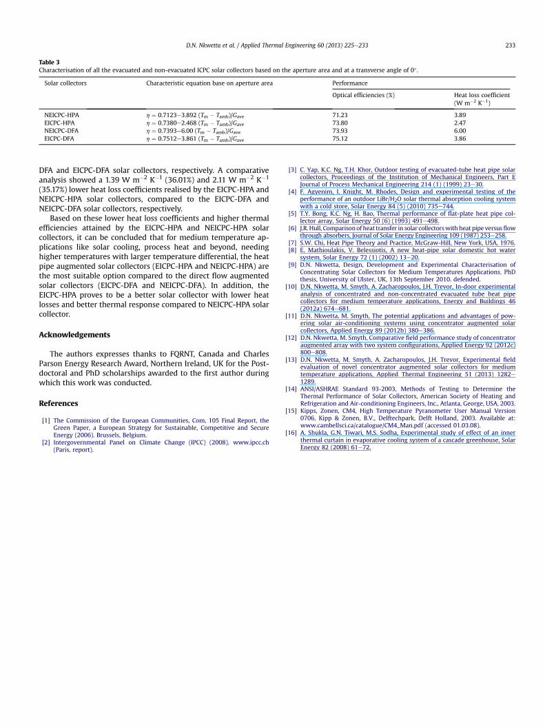
Table 3Characterisation of all the evacuated and non-evacuated ICPC solar collectors based on the aperture area and at a transverse angle of 0� .
Solar collectors Characteristic equation base on aperture area Performance
Optical efficiencies (%) Heat loss coefficient(W m�2 K�1)
NEICPC-HPA h ¼ 0.7123e3.892 (Tm � Tamb)/Gave 71.23 3.89EICPC-HPA h ¼ 0.7380e2.468 (Tm � Tamb)/Gave 73.80 2.47NEICPC-DFA h ¼ 0.7393e6.00 (Tm � Tamb)/Gave 73.93 6.00EICPC-DFA h ¼ 0.7512e3.861 (Tm � Tamb)/Gave 75.12 3.86
D.N. Nkwetta et al. / Applied Thermal Engineering 60 (2013) 225e233 233
DFA and EICPC-DFA solar collectors, respectively. A comparativeanalysis showed a 1.39 W m�2 K�1 (36.01%) and 2.11 W m�2 K�1
(35.17%) lower heat loss coefficients realised by the EICPC-HPA andNEICPC-HPA solar collectors, compared to the EICPC-DFA andNEICPC-DFA solar collectors, respectively.
Based on these lower heat loss coefficients and higher thermalefficiencies attained by the EICPC-HPA and NEICPC-HPA solarcollectors, it can be concluded that for medium temperature ap-plications like solar cooling, process heat and beyond, needinghigher temperatures with larger temperature differential, the heatpipe augmented solar collectors (EICPC-HPA and NEICPC-HPA) arethe most suitable option compared to the direct flow augmentedsolar collectors (EICPC-DFA and NEICPC-DFA). In addition, theEICPC-HPA proves to be a better solar collector with lower heatlosses and better thermal response compared to NEICPC-HPA solarcollector.
Acknowledgements
The authors expresses thanks to FQRNT, Canada and CharlesParson Energy Research Award, Northern Ireland, UK for the Post-doctoral and PhD scholarships awarded to the first author duringwhich this work was conducted.
References
[1] The Commission of the European Communities, Com, 105 Final Report, theGreen Paper, a European Strategy for Sustainable, Competitive and SecureEnergy (2006). Brussels, Belgium.
[2] Intergovernmental Panel on Climate Change (IPCC) (2008). www.ipcc.ch(Paris, report).
[3] C. Yap, K.C. Ng, T.H. Khor, Outdoor testing of evacuated-tube heat pipe solarcollectors, Proceedings of the Institution of Mechanical Engineers, Part EJournal of Process Mechanical Engineering 214 (1) (1999) 23e30.
[4] F. Agyenim, I. Knight, M. Rhodes, Design and experimental testing of theperformance of an outdoor LiBr/H2O solar thermal absorption cooling systemwith a cold store, Solar Energy 84 (5) (2010) 735e744.
[5] T.Y. Bong, K.C. Ng, H. Bao, Thermal performance of flat-plate heat pipe col-lector array, Solar Energy 50 (6) (1993) 491e498.
[6] J.R. Hull, Comparisonof heat transfer in solar collectorswith heat pipe versusflowthrough absorbers, Journal of Solar Energy Engineering 109 (1987) 253e258.
[7] S.W. Chi, Heat Pipe Theory and Practice, McGraw-Hill, New York, USA, 1976.[8] E. Mathioulakis, V. Belessiotis, A new heat-pipe solar domestic hot water
system, Solar Energy 72 (1) (2002) 13e20.[9] D.N. Nkwetta, Design, Development and Experimental Characterisation of
Concentrating Solar Collectors for Medium Temperatures Applications. PhDthesis, University of Ulster, UK, 13th September 2010. defended.
[10] D.N. Nkwetta, M. Smyth, A. Zacharopoulos, J.H. Trevor, In-door experimentalanalysis of concentrated and non-concentrated evacuated tube heat pipecollectors for medium temperature applications, Energy and Buildings 46(2012a) 674e681.
[11] D.N. Nkwetta, M. Smyth, The potential applications and advantages of pow-ering solar air-conditioning systems using concentrator augmented solarcollectors, Applied Energy 89 (2012b) 380e386.
[12] D.N. Nkwetta, M. Smyth, Comparative field performance study of concentratoraugmented array with two system configurations, Applied Energy 92 (2012c)800e808.
[13] D.N. Nkwetta, M. Smyth, A. Zacharopoulos, J.H. Trevor, Experimental fieldevaluation of novel concentrator augmented solar collectors for mediumtemperature applications, Applied Thermal Engineering 51 (2013) 1282e1289.
[14] ANSI/ASHRAE Standard 93-2003, Methods of Testing to Determine theThermal Performance of Solar Collectors, American Society of Heating andRefrigeration and Air-conditioning Engineers, Inc., Atlanta, George, USA, 2003.
[15] Kipps, Zonen, CM4, High Temperature Pyranometer User Manual Version0706, Kipp & Zonen, B.V., Delftechpark, Delft Holland, 2003. Available at:www.cambellsci.ca/catalogue/CM4_Man.pdf (accessed 01.03.08).
[16] A. Shukla, G.N. Tiwari, M.S. Sodha, Experimental study of effect of an innerthermal curtain in evaporative cooling system of a cascade greenhouse, SolarEnergy 82 (2008) 61e72.
Related Documents