Experimental investigations on scaled-up methane hydrate production with surfactant promotion: Energy considerations Lucia Brinchi a,n , Beatrice Castellani b , Federico Rossi a,b , Franco Cotana a , Elena Morini a , Andrea Nicolini a,b , Mirko Filipponi a,b a CIRIAF, Interuniversity Research Center on Pollution Control and Enviromental Protection “Mauro Felli”, University of Perugia, Industrial Engineering Department, Via G. Duranti 67, 06125 Perugia, Italy b Consorzio IPASS Scarl, Via G. Guerra 23, 06127 Perugia, Italy article info Article history: Received 31 October 2013 Accepted 15 June 2014 Available online 23 June 2014 Keywords: methane hydrate surfactant scale-up water spraying hydrate formation energy cost abstract An investigation about methane hydrate formation in a water spraying reactor with an inner volume of 25 L was carried out. In particular, the effects of changes in operational parameters were studied, in order to gain a deeper understanding of factors that play major roles on the energy cost of the whole process. Parameters changed include surfactant addition, spraying time, gas pressure, water amount loaded, and differential pressure on gas nozzles. Rapid methane hydrate formation is achieved only with sodium dodecyl sulfate surfactant promotion in all conditions tested, with reaction times in the range of few tens of minutes. Analysis of the energy cost for various steps of the process shows how reaction time (in the range used) and gas cooling work have quite negligible contribution, whereas gas compression work gives by far the main energy cost. & 2014 Elsevier B.V. All rights reserved. 1. Introduction Gas hydrates are nanostructured crystalline materials in which small hydrophobic guest molecules are trapped inside cages of host water molecules (Sloan, 1998; Sloan and Koh, 2008). Growing interest has been focused in the last few years upon methane hydrate, due to the numerous possible applications in the broad area of energy and climate effects (Sloan, 2003; Sloan and Koh, 2008). Objects of specific investigations include: Flow assurance: oil and gas pipelines in cold regions/deep seas tend to form methane hydrates which eventually block the pipeline (Sloan, 2003; Di Profio et al. 2007). Research currently focuses on the search of hydrate inhibitors, especially low- dosage hydrate inhibitors (Masoudi and Tohidi, 2010; Seo and Kang, 2012). Unconventional energy source: the amount of energy stored in methane hydrate form in subcontinental margins and perma- frost regions is estimated to at least equal to the overall amount of the other fossil fuels combined, and the research about locat- ing resources and methane production from hydrate bearing sediments is increasing every year (Fitzgerald et al., 2012). Furthermore, methane, after its release, may be used in low environmental impact energy production devices such as molten carbonate fuel cells (Rossi and Nicolini, 2011). Global climate issues: methane is a much stronger green-house gas than carbon dioxide: a global warming of 4–8 1C in the geological past has been ascribed to an abrupt methane release from submarine hydrates (Kennett et al., 2003). Separation of CO 2 from mixed gas in a form of gas hydrate: it is expected to be an alternative method for capturing carbon at the extensive emission sites, or for purifying biogas or syngas (Li et al., 2010; Rufford et al., 2012); moreover simultaneous CO 2 sequestration and CH 4 production has also been recently considered (Bi et al., 2013). Storage and transportation: GH technology may be applied to the safe storage and transportation of natural gas in general. In particular, storing and transporting natural gas as hydrate medium, especially from remote gas fields, is one of the most promising applications of gas hydrates. It is estimated that 70% of the total gas reserve is either too far from an existing pipeline or too small to justify a liquefaction facility (Sloan, 2003). Gudmundsson et al. (1992) and Gudmundsson and Børrehaug (1996) of Norwegian University of Science and Technology sug- gested that natural gas hydrates (NGH) are expected to become a new medium for energy storage and transport, and they also published a feasibility study showing a cost saving of 24% for the Contents lists available at ScienceDirect journal homepage: www.elsevier.com/locate/petrol Journal of Petroleum Science and Engineering http://dx.doi.org/10.1016/j.petrol.2014.06.015 0920-4105/& 2014 Elsevier B.V. All rights reserved. n Corresponding author. Tel.: þ39 075 585 3914. E-mail addresses: [email protected] (B. Lucia), [email protected] (B. Castellani), [email protected] (F. Rossi), [email protected] (F. Cotana), [email protected] (E. Morini), [email protected] (A. Nicolini), fi[email protected] (M. Filipponi). Journal of Petroleum Science and Engineering 120 (2014) 187–193

Welcome message from author
This document is posted to help you gain knowledge. Please leave a comment to let me know what you think about it! Share it to your friends and learn new things together.
Transcript
Experimental investigations on scaled-up methane hydrate productionwith surfactant promotion: Energy considerations
Lucia Brinchia,n, Beatrice Castellani b, Federico Rossi a,b, Franco Cotana a, Elena Morini a,Andrea Nicolini a,b, Mirko Filipponi a,b
a CIRIAF, Interuniversity Research Center on Pollution Control and Enviromental Protection “Mauro Felli”, University of Perugia,Industrial Engineering Department, Via G. Duranti 67, 06125 Perugia, Italyb Consorzio IPASS Scarl, Via G. Guerra 23, 06127 Perugia, Italy
a r t i c l e i n f o
Article history:Received 31 October 2013Accepted 15 June 2014Available online 23 June 2014
Keywords:methane hydratesurfactantscale-upwater sprayinghydrate formationenergy cost
a b s t r a c t
An investigation about methane hydrate formation in a water spraying reactor with an inner volume of25 L was carried out. In particular, the effects of changes in operational parameters were studied, inorder to gain a deeper understanding of factors that play major roles on the energy cost of the wholeprocess. Parameters changed include surfactant addition, spraying time, gas pressure, water amountloaded, and differential pressure on gas nozzles. Rapid methane hydrate formation is achieved only withsodium dodecyl sulfate surfactant promotion in all conditions tested, with reaction times in the range offew tens of minutes. Analysis of the energy cost for various steps of the process shows how reaction time(in the range used) and gas cooling work have quite negligible contribution, whereas gas compressionwork gives by far the main energy cost.
& 2014 Elsevier B.V. All rights reserved.
1. Introduction
Gas hydrates are nanostructured crystalline materials in whichsmall hydrophobic guest molecules are trapped inside cages ofhost water molecules (Sloan, 1998; Sloan and Koh, 2008). Growinginterest has been focused in the last few years upon methanehydrate, due to the numerous possible applications in the broadarea of energy and climate effects (Sloan, 2003; Sloan and Koh,2008). Objects of specific investigations include:
� Flow assurance: oil and gas pipelines in cold regions/deep seastend to form methane hydrates which eventually block thepipeline (Sloan, 2003; Di Profio et al. 2007). Research currentlyfocuses on the search of hydrate inhibitors, especially low-dosage hydrate inhibitors (Masoudi and Tohidi, 2010; Seo andKang, 2012).
� Unconventional energy source: the amount of energy stored inmethane hydrate form in subcontinental margins and perma-frost regions is estimated to at least equal to the overall amountof the other fossil fuels combined, and the research about locat-ing resources and methane production from hydrate bearing
sediments is increasing every year (Fitzgerald et al., 2012).Furthermore, methane, after its release, may be used in lowenvironmental impact energy production devices such asmolten carbonate fuel cells (Rossi and Nicolini, 2011).
� Global climate issues: methane is a much stronger green-housegas than carbon dioxide: a global warming of 4–8 1C in thegeological past has been ascribed to an abrupt methane releasefrom submarine hydrates (Kennett et al., 2003).
� Separation of CO2 from mixed gas in a form of gas hydrate: it isexpected to be an alternative method for capturing carbon atthe extensive emission sites, or for purifying biogas or syngas(Li et al., 2010; Rufford et al., 2012); moreover simultaneousCO2 sequestration and CH4 production has also been recentlyconsidered (Bi et al., 2013).
� Storage and transportation: GH technology may be applied tothe safe storage and transportation of natural gas in general.
In particular, storing and transporting natural gas as hydratemedium, especially from remote gas fields, is one of the mostpromising applications of gas hydrates. It is estimated that 70% ofthe total gas reserve is either too far from an existing pipeline ortoo small to justify a liquefaction facility (Sloan, 2003).Gudmundsson et al. (1992) and Gudmundsson and Børrehaug(1996) of Norwegian University of Science and Technology sug-gested that natural gas hydrates (NGH) are expected to become anew medium for energy storage and transport, and they alsopublished a feasibility study showing a cost saving of 24% for the
Contents lists available at ScienceDirect
journal homepage: www.elsevier.com/locate/petrol
Journal of Petroleum Science and Engineering
http://dx.doi.org/10.1016/j.petrol.2014.06.0150920-4105/& 2014 Elsevier B.V. All rights reserved.
n Corresponding author. Tel.: þ39 075 585 3914.E-mail addresses: [email protected] (B. Lucia),
[email protected] (B. Castellani), [email protected] (F. Rossi),[email protected] (F. Cotana), [email protected] (E. Morini),[email protected] (A. Nicolini), [email protected] (M. Filipponi).
Journal of Petroleum Science and Engineering 120 (2014) 187–193

transport of natural gas in hydrates form compared to liquefiednatural gas (LNG). The storage and transportation of gas as NGH isappealing for industrial utilization also because of its high safetyfor both human beings and the environment. In fact NGH do notexplode in the event of a fire or tank rupture, but burn or releaseits contents slowly; NGH do not request heavy-duty containers forstoring due to a much lower vapor pressure compared withnormal pressure of loading of a pressurized tank; finally, NGHuse water as storage medium, which has a “zero” environmentalimpact (Di Profio et al., 2007).
Despite mentioned advantages, the feasibility of using clathratehydrates for industrial purposes has long been an intriguingsubject of engineering studies (Lang et al., 2010; Okutani et al.,2008). Also the Japanese company Mitsui Engineering & Shipbuild-ing, which demonstrated operation of large scale plant and hasbeen working on the improving the economics of transportationsince 2001, is still searching to improve the GH production, and iscurrently focusing on development of methods for increasing theenergy density improving pellet formation (Muruyama et al.,2011). Generally speaking, the main issues include the slowformation rates, unreacted interstitial water as a large percentageof the hydrate mass, economy of process scale-up (Lang et al.,2010). The lack of a technology that allows the production ofhydrate in a continuous manner suitable for scale-up to industrialsettings has hindered the utilization of gas hydrates in the possibleapplications. Hydrate formation is always the first process in anyof these yet-to-be established technologies. Some authors pro-posed that the reduction of power consumption is of primaryimportance for the implementation of the NGH transport process,with more than 70% of power consumption attributable to hydrateformation in the absence of surfactants (Daimaru et al., 2007).Thus, how to efficiently form hydrates is a technical task researchof rather wide interest (Lang et al., 2010).
Among the solutions to increase the hydrate formation rate andstorage capacity, development and improvement of reactors havebeen carried out, with the aim of increasing mass transferprocesses. Stirring reactors, and bubble towers have been tested,with some problems (Lang et al., 2010). Spraying reactor is a typeof reactor for gas–liquid reactant systems, whose application formethane hydrate formation has been studied by Mori et al., whodesigned and modified spraying reactors (Ohmura et al., 2002;Tsuji et al., 2004). This kind of reactor has to be considered thebest for applications to scaled-up systems, and a scaled-up spray-ing reactor for hydrate production was designed (Brinchi et al.,
2011; Rossi et al., 2012) and improved (Castellani et al., 2013) inCIRIAF lab.
In this work, this spraying reactor – already used in CIRIAF labfor CO2 capture (Castellani et al., 2013) – was used to investigatemethane hydrate production. The reactor is a scaled-up sprayingreactor, with inner volume of 25 L, and 6 nozzles. The mainobjective of experimentation is to have a deeper understandingof the various contributions to the total energy cost necessary forthe whole process of GH production, with the final aim of loweringenergy costs of hydrate formation. The use of surfactants promo-tion is used. Their effects on chemical reaction rates and equilibriahave been studied for many years, with special attention to roomtemperature conditions in aqueous media (Fendler, 1982). Cur-rently, investigations of surfactant effects have enlarged to a widebroader temperature range also to exploit various applications (DiMichele et al., 2011, 2013; Weerasooriya et al., 2011). The previousstudies reported that addition of surfactant to liquid water causesa drastic promotion on the rate of formation and occupancy of gashydrates, and decreases the induction time, even in unstirredreactors (Zhong and Rogers, 2000; Di Profio et al., 2007, 2011;Ganji et al., 2007; Okutani et al., 2008; Lang et al., 2010; Ando etal., 2012; Lo et al., 2012). In particular, a recent investigationabout a great number of surfactants (both commercial and not) ofvarious charge type, various hydrophobic/hydrophilic balance,various chemical nature of the polar head group showed hownegatively charged compounds are strong methane hydrate pro-moters (Di Profio et al., 2011). In the present work, anionicsurfactant sodium dodecyl sulfate, SDS, was used which seemsthe best commercially available surfactant for improvement ofmethane hydrate formation (Di Profio et al., 2011).
2. Materials and method
2.1. The reactor
The general design of the present experiments followed that ofprevious tests performed in CIRIAF lab, in which CO2 was used asguest gas (Castellani et al., 2013). Fig. 1 schematically shows theexperimental setup used in the current investigation.
The main feature of the apparatus used for gas hydrateformation is a large volume: 25 L. Most laboratory reactors foundin literature have a volume of about few hundreds mL, up to 1 L(Lang et al., 2010). A bigger size results in scale effects to be
Fig. 1. Scheme of the reactor for gas hydrate production.
B. Lucia et al. / Journal of Petroleum Science and Engineering 120 (2014) 187–193188
investigated for future industrial scale-up. It is a spraying reactorwhich also allows for recirculation of the pressurized aqueoussolution through a recirculation pump. It is possible to control thegas pressure, the differential pressure on the nozzles, and to setthe recirculation time wanted. The system can be set to stoprecirculation of water when it is no longer present in the liquidstate. The reactor is provided with pressure transducers, tempera-ture sensors and data acquisition system.
2.2. Procedure for production of gas hydrates
The reactor was used to produce methane hydrates throughspraying aqueous solution into the gas phase. The establishedamount of aqueous solution is firstly uploaded and the reactor isthen evacuated to about 1 mbar with the vacuum pump, filledwith gas from gas bottles until the internal pressure equals theexperimental pressure and then cooled. Gas is bubbled into theliquid phase through five check valves.
The temperature is controlled in order to achieve relativelyuniform values inside the reactor. When the experimental condi-tions are reached, aqueous solution is flowed by the recirculationpump through the nozzles. Since the flow rate of aqueous solutionthrough the nozzles depends on the differential pressure onnozzles themselves, the water spraying is continued for severalminutes until the established total amount of aqueous solution isatomized. Sometimes, water recirculation is continued until thetotal amount of water uploaded is converted into hydrates. Eachexperiment is carried out with a constant internal pressure. Whenthe internal pressure decreases because of hydrate formation, gasis injected into the reactor to re-establish the correct pressurevalue. When the pressure exceeds the set value, gas is vented out.Investigations were carried out in batch conditions. Therefore, atthe end of each experiment, gas is vented out from gas outlet port.After reducing internal pressure to barometric level, a flange isopened both for visual observations and for taking hydratesamples out for characterization.
2.3. Evaluation of gas content in the hydrates
At the end of each experiment, gas is vented out from gasinjection port through a three-way valve. The reactor is opened totake hydrate samples out for characterization in terms of gascontent. Pressure reduction to barometric level allows to achievean internal temperature range from 255 to 270 K. Within thisrange very low hydrate dissociation rates are observed thanks tothe so-called ‘self-preservation effect’ (Yakushev and Istomin,1992). Therefore, storage capacity values may be only slightlyunderestimated. Hydrate storage capacity was reported in wt%(weight percentage) of gas contained in the hydrate sample.Hydrate storage capacity is determined by putting hydrate sam-ples inside a custom built dissociation vessel, whose character-istics are reported in Rossi et al. (2012). After sealing the vessel,dissociation starts and gas pressure and temperature after dis-sociation are measured. To calculate the gas weight, the pressureand temperature values are used to determine the value of den-sity by using the equation of state reported in NIST ChemistryWebBook (Lemmon et al., 2013).
2.4. Materials
Given the potential industrial applications, the experimentswere carried out by using materials with a proper balancebetween purity and cost. Nitrogen (99.999% purity) and methane(99% purity) were supplied by Air Liquide Italia Service. Followingthe results by Pang et al. (2007) about the use of tap water inmethane hydrate formation in scaled-up system, the tap water
was used to prepare solutions instead of the more expensivedistilled water. SDS (purity498%) was from Sigma Aldrich.
3. Calculation
The total energy involved in the technology from compressionto the removal of reaction heat was calculated for each experi-mental run. The total energy has been calculated, following themethodology already used for hydrogen hydrates (Di Profio et al.,2009), as the sum of several contributions: (i) energy spent tobring methane to formation conditions (compression and coolingenergy), (ii) energy spent to remove reaction heat, (iii) energyspent for recirculation of aqueous solution. Release processes fromhydrates require a very low energy. Hydrate dissociation can beobtained by simply providing enthalpy of dissociation; being thesystem at quite low temperatures, even heat at ambient tempera-ture can be used, thus resulting in dissociation costs equal to zero.Energy costs are calculated in Wh spent in each experimental runand in kWh/kg of stored methane. Some hypotheses on processesand gas properties were assumed. To calculate the work of com-pression, 3-stage adiabatic compressions with inter-cooling until293 K are considered, with a compression efficiency ηcompr of 85%.The cooling down process to the experimental temperature iscarried out by a chiller. The coefficient of performance (COP) wasconsidered equal to 3. The cooling energy is calculated for both thegas and the liquid water. Hydrate formation is an exothermicprocess. To ensure a constant temperature during the entireprocess, the released heat must be removed. The coefficient ofperformance was considered equal to 3. The enthalpy of formationfor CH4 hydrates is 52.9 kJ/mol (Anderson, 2004). The energy costsfor recirculation of the aqueous solution are due to pump work,proportional to the reaction time and differential pressure onspraying nozzles. The efficiency is assumed to be 0.85.
4. Results and discussion
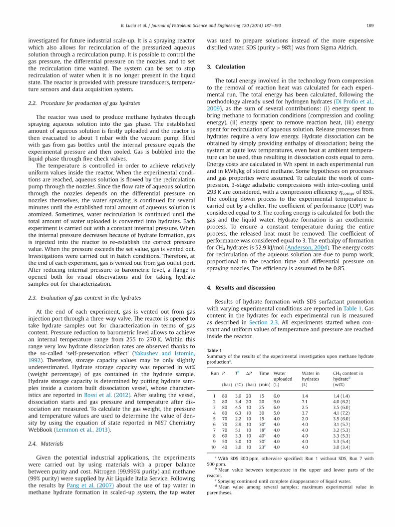
Results of hydrate formation with SDS surfactant promotionwith varying experimental conditions are reported in Table 1. Gascontent in the hydrates for each experimental run is measuredas described in Section 2.3. All experiments started when con-stant and uniform values of temperature and pressure are reachedinside the reactor.
Table 1Summary of the results of the experimental investigation upon methane hydrateproductiona.
Run P Tb ΔP Time Wateruploaded
Water inhydrates
CH4 content inhydrated
(bar) (1C) (bar) (min) (L) (L) (wt%)
1 80 3.0 20 15 6.0 1.4 1.4 (1.4)2 80 3.4 20 20 9.0 7.1 4.0 (6.2)3 80 4.5 10 25 6.0 2.5 3.5 (6.0)4 80 6.3 10 30 5.0 3.7 4.1 (7.2)5 70 2.2 10 15 4.0 2.0 3.5 (6.0)6 70 2.9 10 30c 4.0 4.0 3.1 (5.7)7 70 5.1 10 18c 4.0 4.0 3.2 (5.3)8 60 3.3 10 40c 4.0 4.0 3.3 (5.3)9 50 3.0 10 30c 4.0 4.0 3.3 (5.4)
10 40 3.0 10 23c 4.0 4.0 3.0 (3.4)
a With SDS 300 ppm, otherwise specified: Run 1 without SDS, Run 7 with500 ppm.
b Mean value between temperature in the upper and lower parts of thereactor.
c Spraying continued until complete disappearance of liquid water.d Mean value among several samples; maximum experimental value in
parentheses.
B. Lucia et al. / Journal of Petroleum Science and Engineering 120 (2014) 187–193 189

During the experiments, pressure and temperature data arecollected every 5 s. Figs. 2 and 3 represent typical profiles of valuesof pressure and temperature vs. time; data reported in this figureare for experimental runs 1 and 2 in Table 1. The pressure is thetotal pressure inside the reactor, and the temperature values aretwo, because two different positions inside the reactor are mon-itored (see Fig. 1). Water spraying starts at t¼1 min.
As already pointed out, without promoter, the pressure profile(Fig. 2) is constant since there is no gas consumption due tohydrate formation. There are also no important temperaturevariations, as consistent with absence of reaction heat release.The sudden temperature decrease at t¼16 min is due to gas vent.
In Fig. 3, the variation of values of pressure and temperaturesvs. time for methane hydrate formation in SDS 300 ppm (Run 2 inTable 1) clearly shows a rapid methane hydrate formation, evidentfrom the temperature increase and pressure decrease. It is impor-tant to underline that in this case hydrates form within the firstminute with negligible induction time. The temperature increaseis important within the first 8 min. After that, the cooling systembrought back temperature to suitable values and temperaturevariations were kept within 2–3 1C. It is noteworthy that, asregards temperature values, the efforts in the reactor design were
devoted to obtain a high level of temperature control. Dealing withtemperature control is one of the important factors deciding theperformance of the hydrate formation for at least two reasons:subcooling and heat removal. In fact, subcooling is generallyrequired for hydrate formation so that it is often considered adriving force for the process (Sloan, 1998; Sloan and Koh, 2008).Furthermore, during the hydrate formation temperature increasesas a result of the exothermic process, and it is of no help in hydrateformation, so that an efficient system for reaction heat removal isnecessary. Moreover, in a scaled-up system there is the furtherproblem of temperature uniformity inside the volume of thereactor. Temperature profiles reported in Fig. 3 show how thesystem for temperature control was able to maintain a relativelyconstant and uniform value of temperature in the reactor duringhydrate formation. As far as pressure profile is concerned, differ-ently from Run 1, pressure is not constant but there are severaldecreases followed by quite regular adjustments to the nominalvalues.
In order to consider hydrate formation from an energy costpoint of view, the total energy involved in each run was calcu-lated with varying experimental conditions. In such a way theenergy cost of various experimental parameters may be evaluated.
Fig. 2. Pressure and temperature profiles for experimental Run 1.
Fig. 3. Pressure and temperature profiles for experimental Run 2.
B. Lucia et al. / Journal of Petroleum Science and Engineering 120 (2014) 187–193190
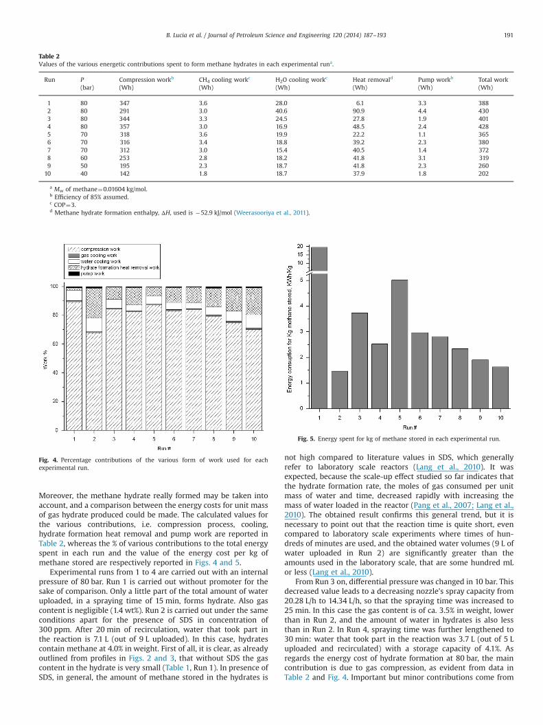
Moreover, the methane hydrate really formed may be taken intoaccount, and a comparison between the energy costs for unit massof gas hydrate produced could be made. The calculated values forthe various contributions, i.e. compression process, cooling,hydrate formation heat removal and pump work are reported inTable 2, whereas the % of various contributions to the total energyspent in each run and the value of the energy cost per kg ofmethane stored are respectively reported in Figs. 4 and 5.
Experimental runs from 1 to 4 are carried out with an internalpressure of 80 bar. Run 1 is carried out without promoter for thesake of comparison. Only a little part of the total amount of wateruploaded, in a spraying time of 15 min, forms hydrate. Also gascontent is negligible (1.4 wt%). Run 2 is carried out under the sameconditions apart for the presence of SDS in concentration of300 ppm. After 20 min of recirculation, water that took part inthe reaction is 7.1 L (out of 9 L uploaded). In this case, hydratescontain methane at 4.0% in weight. First of all, it is clear, as alreadyoutlined from profiles in Figs. 2 and 3, that without SDS the gascontent in the hydrate is very small (Table 1, Run 1). In presence ofSDS, in general, the amount of methane stored in the hydrates is
not high compared to literature values in SDS, which generallyrefer to laboratory scale reactors (Lang et al., 2010). It wasexpected, because the scale-up effect studied so far indicates thatthe hydrate formation rate, the moles of gas consumed per unitmass of water and time, decreased rapidly with increasing themass of water loaded in the reactor (Pang et al., 2007; Lang et al.,2010). The obtained result confirms this general trend, but it isnecessary to point out that the reaction time is quite short, evencompared to laboratory scale experiments where times of hun-dreds of minutes are used, and the obtained water volumes (9 L ofwater uploaded in Run 2) are significantly greater than theamounts used in the laboratory scale, that are some hundred mLor less (Lang et al., 2010).
From Run 3 on, differential pressure was changed in 10 bar. Thisdecreased value leads to a decreasing nozzle's spray capacity from20.28 L/h to 14.34 L/h, so that the spraying time was increased to25 min. In this case the gas content is of ca. 3.5% in weight, lowerthan in Run 2, and the amount of water in hydrates is also lessthan in Run 2. In Run 4, spraying time was further lengthened to30 min: water that took part in the reaction was 3.7 L (out of 5 Luploaded and recirculated) with a storage capacity of 4.1%. Asregards the energy cost of hydrate formation at 80 bar, the maincontribution is due to gas compression, as evident from data inTable 2 and Fig. 4. Important but minor contributions come from
Table 2Values of the various energetic contributions spent to form methane hydrates in each experimental runa.
Run P Compression workb CH4 cooling workc H2O cooling workc Heat removald Pump workb Total work(bar) (Wh) (Wh) (Wh) (Wh) (Wh) (Wh)
1 80 347 3.6 28.0 6.1 3.3 3882 80 291 3.0 40.6 90.9 4.4 4303 80 344 3.3 24.5 27.8 1.9 4014 80 357 3.0 16.9 48.5 2.4 4285 70 318 3.6 19.9 22.2 1.1 3656 70 316 3.4 18.8 39.2 2.3 3807 70 312 3.0 15.4 40.5 1.4 3728 60 253 2.8 18.2 41.8 3.1 3199 50 195 2.3 18.7 41.8 2.3 260
10 40 142 1.8 18.7 37.9 1.8 202
a Mw of methane¼0.01604 kg/mol.b Efficiency of 85% assumed.c COP¼3.d Methane hydrate formation enthalpy, ΔH, used is �52.9 kJ/mol (Weerasooriya et al., 2011).
Fig. 4. Percentage contributions of the various form of work used for eachexperimental run.
Fig. 5. Energy spent for kg of methane stored in each experimental run.
B. Lucia et al. / Journal of Petroleum Science and Engineering 120 (2014) 187–193 191
water cooling and heat removal, whereas pump work and gascooling give negligible contributions. Comparing Runs 2 and 4, theenergy spent for the experimental run is similar, although differ-ently distributed (see Fig. 4) due to the different amounts of gasand water loaded. The methane content in hydrates is also similar,but the amount of hydrates formed are greater in Run 2, whichleads to a much more favorable value of the ratio energy spent/kgof methane stored, as shown in Fig. 5.
In order to investigate less energy-demanding conditions formethane hydrate formation, the pressure was systematicallydecreased. Therefore, Run 5 was carried out with an operatingpressure of 70 bar and a spraying time of 15 min. The uploadedwater amount was 4 L, of which only 2 L formed hydrates. Gascontent was 3.5% in weight. Gas content did not change signifi-cantly in Run 6, carried out in the same conditions as Run 5, withthe only difference that recirculation lasted until there was nomore water left and took 30 min. The lengthening of spraying timeleads to an increase of pump work (it is doubled) which anywaystill give a negligible contribution (Table 2, Runs 5 and 6), but theamount of hydrates is by far greater, which leads to a significantlybetter value of the ratio energy cost/kg methane stored (Fig. 5).Therefore, the following experiments were all carried out with thesystem set to stop recirculation of water when it is no longerpresent in the liquid state. In Run 7, SDS concentration waschanged to 500 ppm. In this case, gas content was quite the samethan that in Run 6 (3.2%) but spraying time was 18 min, shorterthan in Run 6. The total energy cost for the experimental run andthe value of the ratio energy cost/kg methane stored are quitesimilar, so that there is no obvious reason to use an increasedamount of surfactant in the following experiments.
Runs 8–10 were carried out with further decreasing theoperating pressure, respectively to 60 bar, 50 bar and 40 bar. Forthese experiments, spraying times were longer than in theexperiments at higher pressures, and 40, 30 and 23 min werenecessary until disappearance of liquid water at 60, 50 and 40 barrespectively. As already pointed out this increases the contributionof the pump work, which remains anyway negligible. Gas contentin the hydrates does not change significantly with decreasing thepressure, and its value ranges between 3.0 and 3.5 wt%, withpressure changing within 70 to 40 bar; moreover the quantity ofhydrates is always 4 L. Comparing runs 6, 8, 9, 10, the energy costof hydrate formation is regularly decreasing with decreasingpressure, considering the parameters of total energy cost, andthe ratio energy cost/kg methane stored, and the compressionwork is the main energy contribution (Figs. 4 and 5).
Therefore, from an energy point of view the use of lowerpressures (40 bar) seems quite useful, due to the decreasedcompression work, which is the main contribution in all theprocesses investigated for methane hydrate formation. In fact,the use of a pressure of 40 bar does not lead to decreased methanecontent in the hydrates nor to significantly lengthened sprayingtimes. Although probably counterintuitive with the importantcontribution of compression work, the use of high pressure(80 bar) is rather energy effective, and the value of energy cost/kg methane stored is the best one for Run 2. In fact, in this case abig quantity of gas hydrates forms, and the quality (i.e. methanecontent) is rather good.
5. Conclusions
In conclusion, for the 25 L reactor developed and in the experi-mental conditions used, rapid methane hydrate formation isachieved with SDS promotion in all conditions tested, withreaction times in the range of few tens of minutes instead ofhundreds of minutes used in the literature also in the lab scale.
Improvement of the GH production is achieved if water spraying iscontinued, with recirculation of water, until disappearance ofliquid water. The amount of water loaded was up to 9 L, with upto 7 L of hydrates formed. Energy considerations about the variouscontributions to total energy necessary in each experimental runshow how the reaction time (in the range used) and the gascooling work have negligible energy cost, whereas the compres-sion work gives by far the main contribution to the energy cost ofthe whole process, so that the pressure conditions are a keyparameter to take into account. The best conditions found formethane hydrate production are: 80 bar, SDS 300 ppm, tempera-ture of 3.4 1C, 9 L water upoloaded, which lead to an energy cost of1.47 kWh/kg methane stored. The second best condition is: 40 bar,SDS 300 ppm, temperature of 3.0 1C, 4 L water uploaded, with anenergy cost of 1.91 kWh/kg methane stored.
On the basis of the carried out analysis, a further improvementin the energy cost of methane hydrate production is necessary, andmay come from improving the gas content in hydrate, which is notgenerally high, since maximum value obtained is far from thetheoretical, which is 13.4% (Sloan, 1998). This would lead to anenergy cost decrease up to a factor of 3 or even 4 at lowerpressures. In this regard, the main problem arises from the scaling-up, because good methane content is achieved in the literaturewith SDS promotion, but with lab scale reactors (Lang et al., 2010).
Other variations in the experimental conditions are plannedand new promoters are under development. In particular, asregards promoters, in order to develop a more environmentalbenign process, the design of new anionic surfactants synthesizedstarting from renewable feedstock is currently going on. The directuse of naturally occurring bio-surfactants is also planned, such asthe recently investigated potato starch, which has led to goodresults in the lab scale (Fakharian et al., 2012).
References
Anderson, G.K., 2004. Enthalpy of dissociation and hydration number of methanehydrate from the Clapeyron equation. J. Chem. Thermodyn. 36, 1119–1127.
Ando, N., Kuwabara, Y., Mori, Y.H., 2012. Surfactant effects on hydrate formation inan unstirred gas/liquid system: an experimental study using methane andmicelle-forming surfactants. Chem. Eng. Sci. 73, 79–85.
Bi, Y., Yang, T., Guo, K.H., 2013. Determination of the upper-quadrupole-phaseequilibrium region for carbon dioxide and methane mixed gas hydrates. J. Pet.Sci. Eng. 101, 62–67.
Brinchi, L., Castellani, B., Cotana, F., Filipponi, M., Rossi, F., Savelli, G., 2011.Investigation on a novel reactor for gas hydrate production. In: Proceedingsof the 7th International Conference on Gas Hydrates, Edinburgh.
Castellani, B., Filipponi, M., Nicolini, A., Cotana, F., Rossi, F., 2013. Carbon dioxidecapture using gas hydrate technology. J. Energy Power Eng. 7, 883–890.
Daimaru, T., Yamasaki, A., Yanagisawa, Y., 2007. Effect of surfactant carbon chainlength on hydrate formation kinetics. J. Pet. Sci. Eng. 56, 89–96.
Di Michele, A., Brinchi, L., Di Profio, P., Germani, R., Savelli, G., Onori, G., 2011. Effectof head group size, temperature, and counterion specificity on cationic micelles.J. Colloid Interface Sci. 358, 160–166.
Di Michele, A., Germani, R., Pastori, G., Spreti, N., Brinchi, L., 2013. Effects oftemperature on micellar-assisted bimolecular reaction of methylnaphthalene-2-sulfonate with bromide and chloride ions. J. Colloid Interface Sci. 402,165–172.
Di Profio, P., Arca, S., Germani, R., Savelli, G., 2007. Novel nanostructured media forgas storage and transport: clathrate hydrates of methane and hydrogen. J. FuelCell Sci. Technol. 4, 49–55.
Di Profio, P., Arca, S., Rossi, F., Filipponi, M., 2009. Comparison of hydrogen hydrateswith existing hydrogen storage technologies: energy and economic evaluations.Int. J. Hydrog. Energy 34, 9173–9180.
Di Profio, P., Marvulli, F., Germani, R., Savelli, G., Cruciani, G., Brinchi, L., 2011. Novellow-concentration amphiphilic inhibitors and thier application to flow assur-ance. X Congresso Nazionale di Chimica Supramolecolare, Perugia.
Fakharian, H., Ganji, H., Naderi Far, A., Kameli, M., 2012. Potato starch as methanehydrate promoter. Fuel 94, 356–360.
Fendler, J.H., 1982. Membrane Mimetic Chemistry. Wiley, New York.Fitzgerald, G.C., Castaldi, M.J., Zhou, Y., 2012. Large scale reactor details and results
for the formation and decomposition of methane hydrates via thermalstimulation dissociation. J. Pet. Sci. Eng. 94–95, 19–27.
Ganji, H., Manteghian, M., Sadaghiani Zadeh, K., Omidkhah, M.R., Rahimi Mofrad,H., 2007. Effect of different surfactants on methane hydrate formation rate,stability and storage capacity. Fuel 86, 434–441.
B. Lucia et al. / Journal of Petroleum Science and Engineering 120 (2014) 187–193192

Gudmundsson, J.S., Børrehaug, A., 1996. Frozen hydrate for transport of natural gas.In: 2nd International Conference on Natural Gas Hydrates Proceedings, Tou-louse, France.
Gudmundsson, J.S., Parlaktuna, M., Khokhar, P., 1992. Storage of natural gas asfrozen hydrate. In: Proceedings of SPE 67th Annual Technical Conference andExhibition, SPE Paper 24924, Washington DC. October 4–7.
Kennett, J.P., Cannariato, G., Hendy, I.L., Behl, R.J., 2003. Methane Hydrates inQuaternary Climate Change: The Clathrate Gun Hypothesis. American Geophy-sics Union, Washington DC.
Lang, X., Fan, S., Wang, Y., 2010. Intensification of methane and hydrogen storage inclathrate hydrate and future prospect. J. Nat. Gas Chem. 19, 203–209.
Lemmon, E.W., McLinden, M.O., Friend, D.G. Thermophysical properties of fluidsystems. In: Linstrom, P.J., Mallard, W.G. (Eds.), NIST Chemistry WebBook, NISTStandard Reference Database Number 69. National Institute of Standards andTechnology, Gaithersburg, MD 20899. ⟨http://webbook.nist.gov⟩ (retrieved05.09.2013).
Li, X.S., Xia, Z.M., Chen, Z.Y., Yan, K.F., Li, G., Wu, H.J., 2010. Gas hydrate formationprocess for capture of carbon dioxide from fuel gas mixture. Ind. Eng. Chem.Res. 49, 11614–11619.
Lo, C., Zhang, J., Somasundaran, P., Lee, J.W., 2012. Investigations of surfactantseffects on gas hydrate formation via infrared spectroscopy. J. Colloid InterfaceSci. 376, 173–176.
Masoudi, R., Tohidi, B., 2010. On modelling gas hydrate inhibition by salts andorganic inhibitors. J. Pet. Sci. Eng. 74, 132–137.
Muruyama, T., Iwabuchi, W., Ito, M., Takahashi, M., 2011. Effects of guest gas onpelletizing performance of natural gas hydrate (NGH) pellets. In: Proceedings ofthe 7th International Conference on Gas Hydrates, Edinburgh.
Ohmura, R., Kashiwazaki, S., Shiota, S., Tsuji, H., Mori, Y.H., 2002. Strucure-I andstructure-H hydrate formation using water spraying. Energy Fuel 16,1141–1147.
Okutani, K., Kuwabara, Y., Mori, Y.H., 2008. Surfactant effects on hydrate formationin an unstirred gas/liquid system: an experimental study using methane andsodium alkyl sulfates. Chem. Eng. Sci. 63, 183–194.
Pang, W.X., Chen, G.J., Dandekar, A., Sun, C.Y., Zhang, C.L., 2007. Experimental studyon the scale-up effect of gas storage in the form of hydrate in a quiescentreactor. Chem. Eng. Sci. 62, 2198–2208.
Rossi, F., Filipponi, M., Castellani, B., 2012. Investigation on a novel reactor for gashydrate production. Appl. Energy 99, 167–172.
Rossi, F., Nicolini, A., 2011. Experimental investigation on a novel electrolyteconfiguration for cylindrical molten carbonate fuel cells. J. Fuel Cell Sci. Technol.8, 1–9.
Rufford, T.E., Smart, S., Watson, G.C.Y., Graham, B.F., Boxall, J., da Costa, J.C.D., May, E.F., 2012. The removal of CO2 and N2 from natural gas: a review of conventionaland emerging process technologies. J. Pet. Sci. Eng. 94–95, 123–154.
Seo, Y., Kang, S.P., 2012. Inhibition of methane hydrate re-formation in offshorepipelines with a kinetic hydrate inhibitor. J. Pet. Sci. Eng. 88–89, 61–66.
Sloan, E.D., Koh, C., 2008. Clathrate Hydrates of Natural Gases, 3rd ed. CRC Press,Boca Raton.
Sloan, E.D., 1998. Clathrate Hydrates of Natural Gases. Marcel Dekker, New York.Sloan, E.D., 2003. Fundamental principles and applications of natural gas hydrates.
Nature 426, 353–359.Tsuji, H., Ohmura, R., Mori, Y.H., 2004. Forming structure-H hydrates using water
spraying in methane gas: effect of chemical species of large-molecule guestsubstances. Energy Fuel 18, 418–424.
Weerasooriya, U.P., Pope, G.A., Nguyen, Q.P., 2011. Composition and methods forcontrolling the stability of ether sulfate surfactants at elevated temperatures.U.S. Patent Application Publication US 20110059872.
Yakushev, V.S., Istomin, V.A., 1992. Gas hydrates self-preservation effect, Physicsand Chemistry of Ice. Hokkaido University Press, Sapporo.
Zhong, Y., Rogers, R.E., 2000. Surfactant effects on gas hydrate formation. Chem.Eng. Sci. 55, 4175–4187.
B. Lucia et al. / Journal of Petroleum Science and Engineering 120 (2014) 187–193 193
Related Documents