Journal of the Mechanics and Physics of Solids 54 (2006) 1568–1603 Experimental investigation on macroscopic domain formation and evolution in polycrystalline NiTi microtubing under mechanical force P. Feng, Q.P. Sun Department of Mechanical Engineering, The Hong Kong University of Science and Technology, Clear Water Bay, Kowloon, Hong Kong SAR, China Received 11 March 2005; accepted 28 February 2006 Abstract This paper reports the experimental results on macroscopic deformation instability and domain morphology evolution during stress-induced austenite - martensite (A-M) phase transformation in superelastic NiTi polycrystalline shape memory alloy microtubes. High-speed data and image acquisition techniques were used to investigate the dynamic and quasi-static events which took place in a displacement-controlled quasi-static tensile loading/unloading process of the tube. These events include dynamic formation, self-merging, topology transition, convoluted front motion and front instability of a macroscopic deformation domain. The reported phenomena brought up several fundamental issues regarding the roles of macroscopic domain wall energy and kinetics as well as their interplay with the bulk strain energy of the tube in the observed morphology instability and pattern evolution under a mechanical force. These issues are believed to be essential elements in the theoretical modeling of macroscopic deformation patterns in polycrystals and need systematic examination in the future. r 2006 Elsevier Ltd. All rights reserved. Keywords: NiTi polycrystal; Superelastic shape memory alloy; Phase transformation; Deformation domain and pattern evolution; Macroscopic domain wall energy ARTICLE IN PRESS www.elsevier.com/locate/jmps 0022-5096/$ - see front matter r 2006 Elsevier Ltd. All rights reserved. doi:10.1016/j.jmps.2006.02.005 Corresponding author. Tel.: +852 2358 8655; fax: +852 2358 1543. E-mail address: [email protected] (Q.P. Sun).

Welcome message from author
This document is posted to help you gain knowledge. Please leave a comment to let me know what you think about it! Share it to your friends and learn new things together.
Transcript
ARTICLE IN PRESS
Journal of the Mechanics and Physics of Solids
54 (2006) 1568–1603
0022-5096/$ -
doi:10.1016/j
�CorrespoE-mail ad
www.elsevier.com/locate/jmps
Experimental investigation on macroscopic domainformation and evolution in polycrystalline NiTi
microtubing under mechanical force
P. Feng, Q.P. Sun�
Department of Mechanical Engineering, The Hong Kong University of Science and Technology,
Clear Water Bay, Kowloon, Hong Kong SAR, China
Received 11 March 2005; accepted 28 February 2006
Abstract
This paper reports the experimental results on macroscopic deformation instability and domain
morphology evolution during stress-induced austenite - martensite (A-M) phase transformation
in superelastic NiTi polycrystalline shape memory alloy microtubes. High-speed data and image
acquisition techniques were used to investigate the dynamic and quasi-static events which took place
in a displacement-controlled quasi-static tensile loading/unloading process of the tube. These events
include dynamic formation, self-merging, topology transition, convoluted front motion and front
instability of a macroscopic deformation domain. The reported phenomena brought up several
fundamental issues regarding the roles of macroscopic domain wall energy and kinetics as well as
their interplay with the bulk strain energy of the tube in the observed morphology instability and
pattern evolution under a mechanical force. These issues are believed to be essential elements in the
theoretical modeling of macroscopic deformation patterns in polycrystals and need systematic
examination in the future.
r 2006 Elsevier Ltd. All rights reserved.
Keywords: NiTi polycrystal; Superelastic shape memory alloy; Phase transformation; Deformation domain and
pattern evolution; Macroscopic domain wall energy
see front matter r 2006 Elsevier Ltd. All rights reserved.
.jmps.2006.02.005
nding author. Tel.: +852 2358 8655; fax: +852 2358 1543.
dress: [email protected] (Q.P. Sun).
ARTICLE IN PRESSP. Feng, Q.P. Sun / J. Mech. Phys. Solids 54 (2006) 1568–1603 1569
1. Introduction
Considerable effort and advances, both theoretical and experimental, have beenwitnessed in the past decades on the investigation of mechanical behaviors of NiTi shapememory alloys. However, in the aspect of deformation instability and the resulted domainpattern evolution of the material during phase transition, for both single crystalsand polycrystals, more experimental efforts are clearly needed. Much of the previousexperimental research on deformation instability in polycrystalline NiTi during phasetransition (see Miyazaki et al., 1981; Leo et al., 1993; Shaw and Kyriakides, 1995,1997; Brinson et al., 2004 and the references therein) were focused on strip and wiresamples under isothermal and/or non-isothermal phase transitions. It is known that thephase transition in NiTi polycrystals is first order in nature and involves intrinsicinstability and domain evolution at microscopic level. Thus complicated microstructureinteraction and evolution inside the polycrystal are inherent in the transformationprocess. Under certain conditions, they may even percolate up to the macroscopic level,leading to macroscopic scale domain formation and evolution, as demonstrated throughmechanical response and surface morphology. However, exact and detailed observationson pattern evolution in structures like thin walled tubes have not been available inthe literature.
Experimental research on deformation instability of NiTi in microtube configurationstarted only in recent years (Berg, 1997; Li and Sun, 2000, 2002; Sun and Li, 2002). It ismotivated by the successful application of microtubes in human implants and surgeryinstruments. In addition to the facilitation of biaxial loading, the advantage ofusing the tube configuration is that an isolated high strain domain (martensite phase)can survive in the tube after its nucleation from the austenite matrix and thatdeformation patterns associated with the domain evolution during the loadingprocess can be produced and observed. The microtubes are usually polycrystalline andnano-grained, with an outer diameter ranging from the smallest of 0.06to several millimetres and length of a few meters. They are manufactured by colddrawing, therefore the texture of the tubes could be very strong which will givesignificant anisotropy in both elastic and transformation properties. Previous preliminarystudy by the authors showed that the transformation process in such a nano-grained polycrystal involves both micro- and macroscopic instabilities and is multi-scalein nature (see Bhattacharye, 2003; Bhattacharye, et al., 2004 and the referencestherein) and that macroscopic deformation instability under tension manifested itselfnot only through sharp stress jumps in the nominal stress–strain curves of the tube but alsothrough the various evolving deformation patterns as revealed by careful tube surfaceobservations.
This paper reports some of the key results from the authors’ recent experimentalinvestigation on macroscopic domain formation and evolution in the superelasticpolycrystalline NiTi microtubing under uniaxial tensile force. The purpose of the researchis to obtain quantitative information on the spatiotemporal evolution of the deformationpatterns through systematic measurement and eventually to provide critical data for futuretheoretical development of this type of material. The material properties and testprocedures are described in Section 2. Section 3 gives a detailed description of theexperimental results. Discussions of the results are given in Section 4 and the conclusionsare given in Section 5.
ARTICLE IN PRESSP. Feng, Q.P. Sun / J. Mech. Phys. Solids 54 (2006) 1568–16031570
2. Materials and experimental procedures
2.1. Material characterization and sample preparation
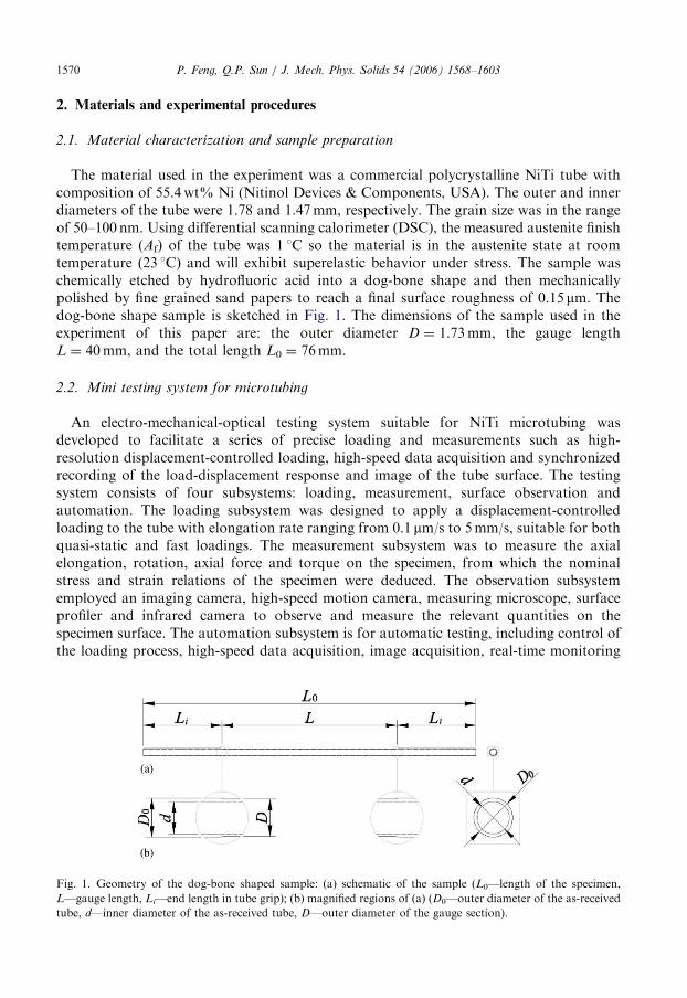
The material used in the experiment was a commercial polycrystalline NiTi tube withcomposition of 55.4wt% Ni (Nitinol Devices & Components, USA). The outer and innerdiameters of the tube were 1.78 and 1.47mm, respectively. The grain size was in the rangeof 50–100 nm. Using differential scanning calorimeter (DSC), the measured austenite finishtemperature (Af) of the tube was 1 1C so the material is in the austenite state at roomtemperature (23 1C) and will exhibit superelastic behavior under stress. The sample waschemically etched by hydrofluoric acid into a dog-bone shape and then mechanicallypolished by fine grained sand papers to reach a final surface roughness of 0.15 mm. Thedog-bone shape sample is sketched in Fig. 1. The dimensions of the sample used in theexperiment of this paper are: the outer diameter D ¼ 1.73mm, the gauge lengthL ¼ 40mm, and the total length L0 ¼ 76mm.
2.2. Mini testing system for microtubing
An electro-mechanical-optical testing system suitable for NiTi microtubing wasdeveloped to facilitate a series of precise loading and measurements such as high-resolution displacement-controlled loading, high-speed data acquisition and synchronizedrecording of the load-displacement response and image of the tube surface. The testingsystem consists of four subsystems: loading, measurement, surface observation andautomation. The loading subsystem was designed to apply a displacement-controlledloading to the tube with elongation rate ranging from 0.1 mm/s to 5mm/s, suitable for bothquasi-static and fast loadings. The measurement subsystem was to measure the axialelongation, rotation, axial force and torque on the specimen, from which the nominalstress and strain relations of the specimen were deduced. The observation subsystememployed an imaging camera, high-speed motion camera, measuring microscope, surfaceprofiler and infrared camera to observe and measure the relevant quantities on thespecimen surface. The automation subsystem is for automatic testing, including control ofthe loading process, high-speed data acquisition, image acquisition, real-time monitoring
Fig. 1. Geometry of the dog-bone shaped sample: (a) schematic of the sample (L0—length of the specimen,
L—gauge length, Li—end length in tube grip); (b) magnified regions of (a) (D0—outer diameter of the as-received
tube, d—inner diameter of the as-received tube, D—outer diameter of the gauge section).
ARTICLE IN PRESSP. Feng, Q.P. Sun / J. Mech. Phys. Solids 54 (2006) 1568–1603 1571
and synchronizing of the measured data and images. A detailed description of eachsubsystem can be found in the work of Feng (2005). The four subsystems were assembledand tested with a standard specimen. The stress–strain curves obtained by the developedsystems were compared with those by a commercial universal testing machine so that thereliability and accuracy of the systems were assured. The system is able to performtension–torsion combined loading, cooling and heating. In this paper it was only used foraxial loading of tube at room temperature (23 1C).
2.3. Experimental setup
The austenite to martensite (A-M) phase transition of the tube was induced by a quasi-static displacement-controlled uniaxial tension at room temperature on the manufacturedtesting system (see Fig. A.1 in Appendix A). In order to minimize the self-heating effectcaused by the transformation latent heat, all tests were performed at a very low elongationrate of 1.2 mm/s which gave a nominal strain rate of 3� 10�5 s�1. The loading frame wasprecisely manufactured and the axis of the tube and the loading direction were carefullyaligned to achieve a negligible bending moment caused by off-axis tension. The specialtubing grips transferred the tensile force to a uniformly distributed tube surface shear stressat the two end portions of the tube, which effectively avoided stress concentration andproduced a uniform tensile stress in the tube cross section over the 40mm middle portion(gauge section) of the tube.
Deformation domain morphology of the tube surface during loading were obtained bydifferent apparatus such as imaging camera, surface profiler, microscope and high-speedcamera so that comparison between the measured results were possible. An infra-redcamera was used to record the tube surface temperature evolution. The control of theloading process, data acquisition and the synchronized display of the stress–strain curvesand surface morphology on screen, etc., were all facilitated by customized software.
3. Experimental results
The experimental observations reported in this section were repeatable in the tests of thesame specimen for more than 50 loading–unloading cycles with time intervals ranging fromseveral hours to several weeks, though the cyclic effect made the stress drop value smallerand domain fronts less clear. The observed deformation instability and domain evolutionwere also repeatable in the tests on other specimens whose gauge length ranges from 30 to110mm. Even for the specimens directly cut from the as-received tube with a uniform crosssection, similar phenomena were observed.
We will first outline the main deformation features of the tube during tensile loading/unloading in Section 3.1. A detailed description of the deformation and domainmorphology evolution during forward (A-M) and reverse (M-A) transformations willbe given in Sections 3.2–3.6. Section 3.7 describes the path dependence of domainmorphology.
3.1. Main deformation features of NiTi tube during quasi-static loading/unloading
The typical measured macroscopic nominal stress–nominal strain (S–S) curve of the tubeduring loading and unloading is shown in Fig. 2(a) (throughout this paper, the nominal
ARTICLE IN PRESS
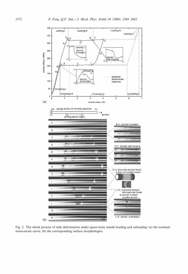
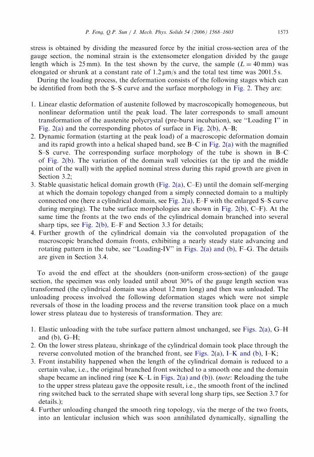
Fig. 2. The whole process of tube deformation under quasi-static tensile loading and unloading: (a) the nominal
stress-strain curve; (b) the corresponding surface morphologies.
P. Feng, Q.P. Sun / J. Mech. Phys. Solids 54 (2006) 1568–16031572
ARTICLE IN PRESSP. Feng, Q.P. Sun / J. Mech. Phys. Solids 54 (2006) 1568–1603 1573
stress is obtained by dividing the measured force by the initial cross-section area of thegauge section, the nominal strain is the extensometer elongation divided by the gaugelength which is 25mm). In the test shown by the curve, the sample (L ¼ 40mm) waselongated or shrunk at a constant rate of 1.2 mm/s and the total test time was 2001.5 s.
During the loading process, the deformation consists of the following stages which canbe identified from both the S–S curve and the surface morphology in Fig. 2. They are:
1.
Linear elastic deformation of austenite followed by macroscopically homogeneous, butnonlinear deformation until the peak load. The later corresponds to small amounttransformation of the austenite polycrystal (pre-burst incubation), see ‘‘Loading I’’ inFig. 2(a) and the corresponding photos of surface in Fig. 2(b), A–B;2.
Dynamic formation (starting at the peak load) of a macroscopic deformation domainand its rapid growth into a helical shaped band, see B–C in Fig. 2(a) with the magnifiedS–S curve. The corresponding surface morphology of the tube is shown in B–Cof Fig. 2(b). The variation of the domain wall velocities (at the tip and the middlepoint of the wall) with the applied nominal stress during this rapid growth are given inSection 3.2;3.
Stable quasistatic helical domain growth (Fig. 2(a), C–E) until the domain self-mergingat which the domain topology changed from a simply connected domain to a multiplyconnected one (here a cylindrical domain, see Fig. 2(a), E–F with the enlarged S–S curveduring merging). The tube surface morphologies are shown in Fig. 2(b), C–F). At thesame time the fronts at the two ends of the cylindrical domain branched into severalsharp tips, see Fig. 2(b), E–F and Section 3.3 for details;4.
Further growth of the cylindrical domain via the convoluted propagation of themacroscopic branched domain fronts, exhibiting a nearly steady state advancing androtating pattern in the tube, see ‘‘Loading-IV’’ in Figs. 2(a) and (b), F–G. The detailsare given in Section 3.4.To avoid the end effect at the shoulders (non-uniform cross-section) of the gaugesection, the specimen was only loaded until about 30% of the gauge length section wastransformed (the cylindrical domain was about 12mm long) and then was unloaded. Theunloading process involved the following deformation stages which were not simplereversals of those in the loading process and the reverse transition took place on a muchlower stress plateau due to hysteresis of transformation. They are:
1.
Elastic unloading with the tube surface pattern almost unchanged, see Figs. 2(a), G–Hand (b), G–H;2.
On the lower stress plateau, shrinkage of the cylindrical domain took place through thereverse convoluted motion of the branched front, see Figs. 2(a), I–K and (b), I–K;3.
Front instability happened when the length of the cylindrical domain is reduced to acertain value, i.e., the original branched front switched to a smooth one and the domainshape became an inclined ring (see K–L in Figs. 2(a) and (b)). (note: Reloading the tubeto the upper stress plateau gave the opposite result, i.e., the smooth front of the inclinedring switched back to the serrated shape with several long sharp tips, see Section 3.7 fordetails.);4.
Further unloading changed the smooth ring topology, via the merge of the two fronts,into an lenticular inclusion which was soon annihilated dynamically, signalling the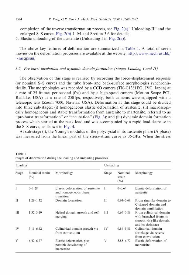
ARTICLE IN PRESS
Tab
Sta
Lo
Sta
I
II
III
IV
V
P. Feng, Q.P. Sun / J. Mech. Phys. Solids 54 (2006) 1568–16031574
completion of the reverse transformation process, see Fig. 2(a) ‘‘Unloading-II’’ and theenlarged S–S curve, Fig. 2(b) L–M and Section 3.6 for details;
5.
Elastic unloading of the austenite (Unloading-I in Fig. 2(a)).The above key features of deformation are summarized in Table 1. A total of sevenmovies on the deformation processes are available at the website: http://www-mech.ust.hk/�meqpsun/
3.2. Pre-burst incubation and dynamic domain formation (stages Loading-I and II)
The observation of this stage is realized by recording the force–displacement response(or nominal S–S curve) and the tube front- and back-surface morphologies synchronis-tically. The morphologies was recorded by a CCD camera (TK-C1381EG, JVC, Japan) ata rate of 25 frames per second (fps) and by a high-speed camera (Motion Scope PCI,Redlake, USA) at a rate of 250 fps, respectively, both cameras were equipped with atelescopic lens (Zoom 7000, Navitar, USA). Deformation at this stage could be dividedinto three sub-stages: (i) homogeneous elastic deformation of austenite; (ii) macroscopi-cally homogeneous and stable transformation from austenite to martensite, referred to as‘‘pre-burst transformation’’ or ‘‘incubation’’ (Fig. 3); and (iii) dynamic domain formationprocess which started at the peak load and was accompanied by a rapid load decrease inthe S–S curve, as shown in Fig. 4.At sub-stage (i), the Young’s modulus of the polycrystal in its austenite phase (A phase)
was measured from the linear part of the stress-strain curve as 35GPa. When the stress
le 1
ges of deformation during the loading and unloading processes
ading Unloading
ge Nominal strain
(%)
Morphology Stage Nominal
strain
(%)
Morphology
0–1.28 Elastic deformation of austenite
and homogeneous phase
transition
I 0–0.64 Elastic deformation of
austenite
1.28–1.32 Domain formation II 0.64–0.69 From ring-like domain to
C-shaped domain and
domain annihilation
1.32–3.19 Helical domain growth and self-
merging
III 0.69–0.86 From cylindrical domain
with branched fronts to
smooth ring-like domain
and its shrinkage
3.19–6.42 Cylindrical domain growth via
front convolution
IV 0.86–5.85 Cylindrical domain
shrinkage via reverse
front convolution
6.42–6.77 Elastic deformation plus
possible detwinning of
martensite
V 5.85–6.77 Elastic deformation of
martensite
ARTICLE IN PRESS
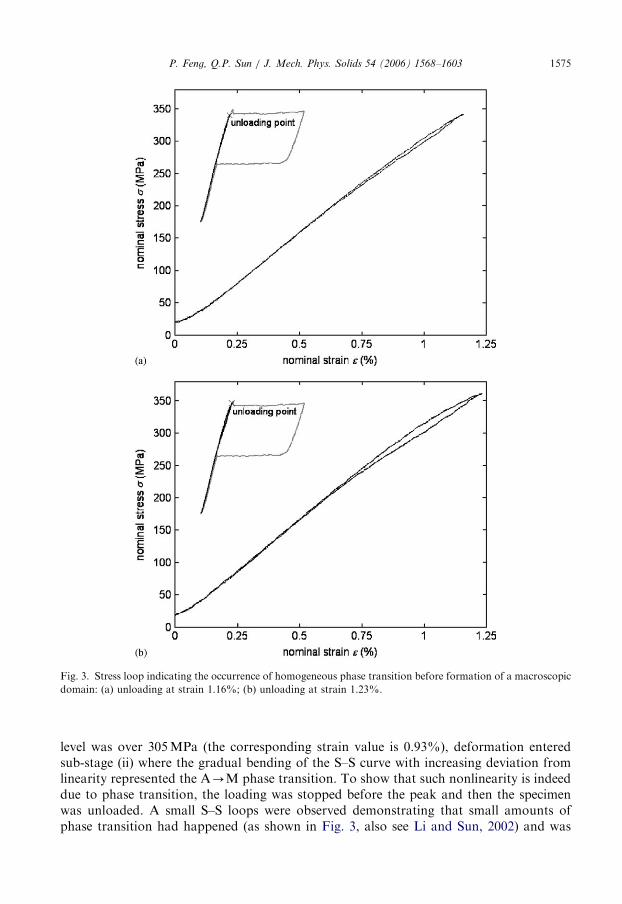
Fig. 3. Stress loop indicating the occurrence of homogeneous phase transition before formation of a macroscopic
domain: (a) unloading at strain 1.16%; (b) unloading at strain 1.23%.
P. Feng, Q.P. Sun / J. Mech. Phys. Solids 54 (2006) 1568–1603 1575
level was over 305MPa (the corresponding strain value is 0.93%), deformation enteredsub-stage (ii) where the gradual bending of the S–S curve with increasing deviation fromlinearity represented the A-M phase transition. To show that such nonlinearity is indeeddue to phase transition, the loading was stopped before the peak and then the specimenwas unloaded. A small S–S loops were observed demonstrating that small amounts ofphase transition had happened (as shown in Fig. 3, also see Li and Sun, 2002) and was
ARTICLE IN PRESS
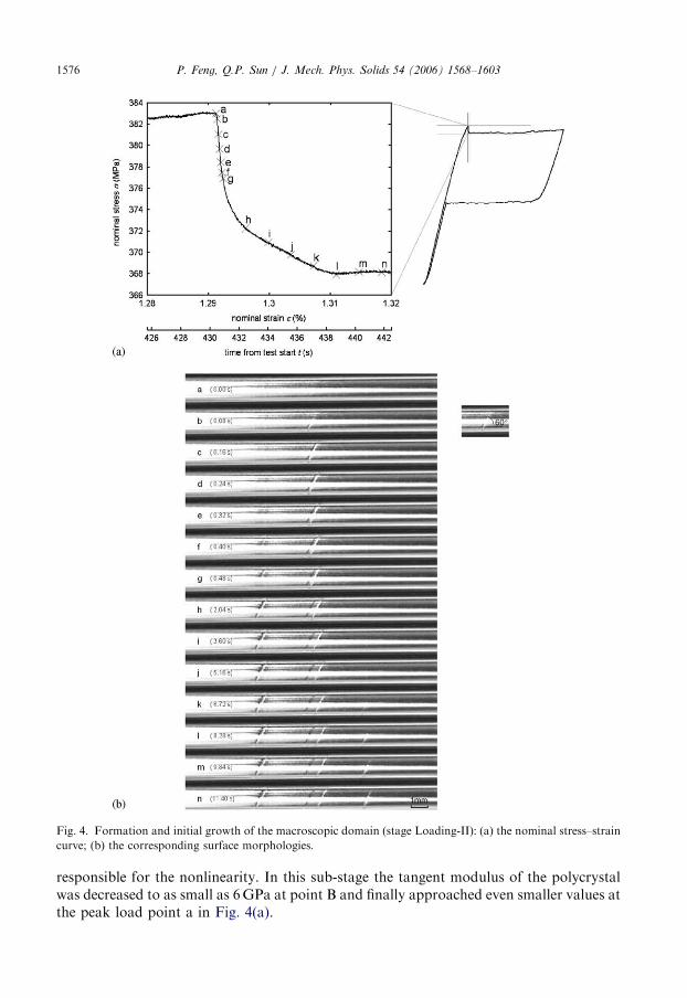
Fig. 4. Formation and initial growth of the macroscopic domain (stage Loading-II): (a) the nominal stress–strain
curve; (b) the corresponding surface morphologies.
P. Feng, Q.P. Sun / J. Mech. Phys. Solids 54 (2006) 1568–16031576
responsible for the nonlinearity. In this sub-stage the tangent modulus of the polycrystalwas decreased to as small as 6GPa at point B and finally approached even smaller values atthe peak load point a in Fig. 4(a).
ARTICLE IN PRESSP. Feng, Q.P. Sun / J. Mech. Phys. Solids 54 (2006) 1568–1603 1577
At sub-stage (iii), soon after the stress reached the peak value at point a (about383MPa), the deformation became inhomogeneous and uncontrollable through thedynamic formation (in the sense that it occurred very rapidly, see the time coordinates inFig. 4(a)) of a macroscopic deformation domain with a concomitant rapid nominal stressdecrease (from 383 to 367MPa) as shown in the sequences a–n in Fig. 4(a). The domain isactually the most transformed high strain region (martensite) of the tube and wasseparated from the almost untransformed austenite (matrix) by a distinct domainboundary (or front region) across which the strain changed rapidly. The domain couldoriginate at any location of the measurement section depending on the defects of thematerial (here it was at the middle portion of the tube). Fig. 4(b) shows the correspondingtube surface images chosen from a sequence of photos taken at 0.08 and 1.56 s timeintervals, respectively. The whole time period during which the load decreased can beclearly divided into two stages. The first stage lasted only about 0.48 s during whichthe load decreased very rapidly (points a–g). In the second stage (which lasted about 7.80 s)the load decreased much more slowly (see points g–l). After this the load reached a stableplateau value and the corresponding domain became a helical band with two spike-liketips. The aspect ratio (length to width) of the band was about 14 as shown in n of Fig. 4(b)(also see Fig. 7(a)).
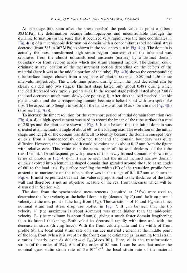
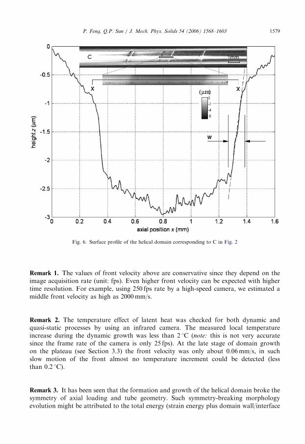
To increase the time resolution for the very short period of initial domain formation (seeFig. 4, a–d), a high-speed camera was used to record the image of the tube surface at a rateof 250 fps and the photos are shown in Fig. 5. It can be seen that the initial domain wasoriented at an inclination angle of about 601 to the loading axis. The evolution of the initialshape and length of the domain was difficult to identify because the domain emerged veryquickly from a homogeneously deformed tube and the domain boundary was quitediffusive. However, the domain width could be estimated as about 0.12mm from the figurewith relative ease. This value is in the same order of the wall thickness of the tube(E0.13mm). The subsequent growth process of this newly formed domain is shown in aseries of photos in Fig. 4, d–n. It can be seen that the initial inclined narrow domainquickly evolved into a lenticular shaped domain that spiraled around the tube at an angleof 601 to the load axis. By surface profiling the width (W) of the transition profile fromaustenite to martensite on the tube surface was in the range of 0.1–0.2mm as shown inFig. 6. It must be pointed out that this value is proportional to the thickness of the tubewall and therefore is not an objective measure of the real front thickness which will bediscussed in Section 4.2.
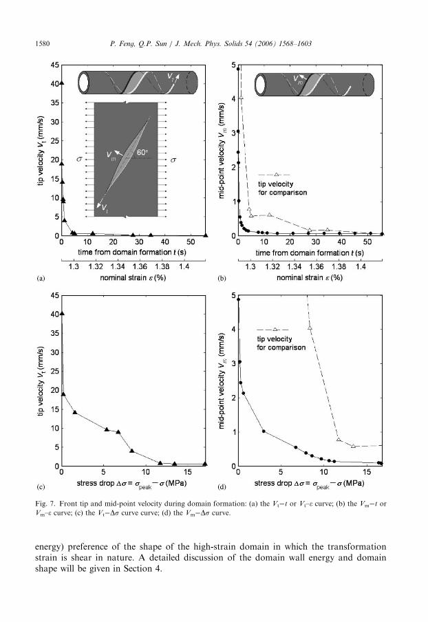
The data from the synchronized measurements (acquired at 25 fps) were used todetermine the front velocity at the helical domain tip (denoted by Vt) and the front normalvelocity at the mid-point of the long front (Vm). The variations of Vt and Vm with time,nominal strain and stress drop are plotted in Fig. 7. It can be seen that the tipvelocity Vt (the maximum is about 40mm/s) was much higher than the mid-pointvelocity Vm (the maximum is about 5mm/s), giving a much faster domain lengtheningthan its lateral thickening. Both velocities decreased rapidly with time and with thedecrease in stress (driving force). With the front velocity data and the width of frontprofile (d), the local axial strain rate of a surface material element at the middle pointof the long front (when it is swept by the front) can be estimated as (assuming total straine varies linearly over d) dðeÞ=dt ¼ eTVm=ðd cos 30�Þ: Here, eT is the transformationstrain (of the order of 5%), d is of the order of 0.1mm. It can be seen that under thenominal quasi-static strain rate of 3� 10�5 s�1 the local strain rate of the material
ARTICLE IN PRESS
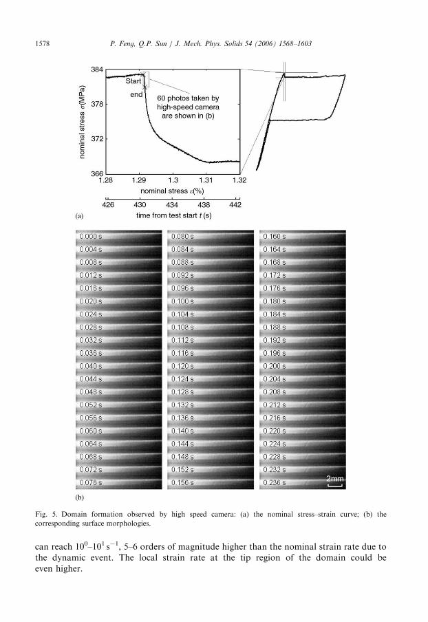
Fig. 5. Domain formation observed by high speed camera: (a) the nominal stress–strain curve; (b) the
corresponding surface morphologies.
P. Feng, Q.P. Sun / J. Mech. Phys. Solids 54 (2006) 1568–16031578
can reach 100–101 s�1, 5–6 orders of magnitude higher than the nominal strain rate due tothe dynamic event. The local strain rate at the tip region of the domain could beeven higher.
ARTICLE IN PRESS
Fig. 6. Surface profile of the helical domain corresponding to C in Fig. 2
P. Feng, Q.P. Sun / J. Mech. Phys. Solids 54 (2006) 1568–1603 1579
Remark 1. The values of front velocity above are conservative since they depend on theimage acquisition rate (unit: fps). Even higher front velocity can be expected with highertime resolution. For example, using 250 fps rate by a high-speed camera, we estimated amiddle front velocity as high as 2000mm/s.
Remark 2. The temperature effect of latent heat was checked for both dynamic andquasi-static processes by using an infrared camera. The measured local temperatureincrease during the dynamic growth was less than 2 1C (note: this is not very accuratesince the frame rate of the camera is only 25 fps). At the late stage of domain growthon the plateau (see Section 3.3) the front velocity was only about 0.06mm/s, in suchslow motion of the front almost no temperature increment could be detected (lessthan 0.2 1C).
Remark 3. It has been seen that the formation and growth of the helical domain broke thesymmetry of axial loading and tube geometry. Such symmetry-breaking morphologyevolution might be attributed to the total energy (strain energy plus domain wall/interface
ARTICLE IN PRESS
Fig. 7. Front tip and mid-point velocity during domain formation: (a) the Vt�t or Vt–e curve; (b) the Vm�t or
Vm–e curve; (c) the Vt�Ds curve curve; (d) the Vm�Ds curve.
P. Feng, Q.P. Sun / J. Mech. Phys. Solids 54 (2006) 1568–16031580
energy) preference of the shape of the high-strain domain in which the transformationstrain is shear in nature. A detailed discussion of the domain wall energy and domainshape will be given in Section 4.
ARTICLE IN PRESSP. Feng, Q.P. Sun / J. Mech. Phys. Solids 54 (2006) 1568–1603 1581
3.3. Quasi-static helical domain growth, self-merging and front branching
(stage Loading-III)
The dynamic domain formation completed as the force dropped to the plateau. The tubethen consisted of a simply connected helical domain and the surrounding austenite matrixas shown by photo n in Fig. 4(b). Further elongation of the tube led to the growth of thismacroscopic helical domain by lengthening and thickening, which proceeded in a stableand controlled manner via visible quasi-static movement of the domain front. Thecorresponding load was kept roughly unchanged on the stress plateau (Fig. 2(a)).
With further loading the low-strain matrix sandwiched in the growing high-straindomain became more and more narrow. Eventually the nearest parts of the two frontsstarted getting touched each other, indicating the self-merging of the domain (see Fig. 8).The merge is again an unstable and dynamic process in the sense that it occurred inan uncontrollable and swift manner as shown by the load drop in the enlarged S–S curvein Fig. 8(a) with time coordinates. The corresponding tube surface images are shown inFigs. 8(b) (the photos), (c) and (d) (3D and plane views, respectively). If we borrow theterminology from material science and presume that front energy (interfacial energy) existsin the polycrystal studied here, the driving force for such a dynamic merge could be fromthe reduction of the system’s total front energy, which caused the two closely paralleledfronts to ‘‘attract’’ each other and led to the speeding-up of the merging process. At thesame time, the merge disconnected the original narrow matrix region in the middle portionof the domain into two regions (left and right portions with long tips in a beak-to-beakmanner as shown in Fig. 8(d)). The process that followed the merge was a gradual stableretreat of the two tips of the austenite phase back to the left and right matrix (see Figs. 8(c)and (d)). Thus the helical domain turned into a cylinder-like one.
Remark 1. The self-merging process changed the domain topology from the originalsimply connected helix to a multiply connected cylinder. Topological transitionscommonly existed in the transformation process of materials such as particle mergingduring the coarsening (e.g. Leo et al., 1998). The deformation domain of the tube wouldexperience several topology transitions in the loading and unloading process as we will seein the following sections.
Remark 2. It was also observed in the present experiment that if the sample were unloaded
prior to the domain self-merging, the domain pattern would evolve reversibly once the loadwas reduced to reach the lower force plateau. The retreat of the domain front caused thehelical domain to shrink almost along its original path and eventually the domain vanisheddynamically (we will be back to this issue in Section 3.7).Remark 3. The fronts at the two ends of the cylindrical domain were not smooth (even a
macroscopic smooth straight front was very rough microscopically). Instead, they weremacroscopically branched with several tips. The formation of the branched shape duringself-merging is still under investigation. The in situ movie of the tube surface morphologyclearly showed that branching took place even before the merge started (see photos a–d inFig. 8(b)). One simple presumption in explaining the branching is that it helps to reduce thestrain energy of the domain (especially near the otherwise smooth front) at the expense ofincreasing the total front length and therefore the total interfacial energy of the front. As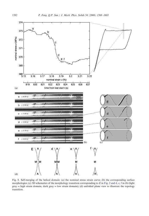
ARTICLE IN PRESS
Fig. 8. Self-merging of the helical domain: (a) the nominal stress–strain curve; (b) the corresponding surface
morphologies; (c) 3D schematics of the morphology transition corresponding to E in Fig. 2 and d, e, f in (b) (light
gray ¼ high strain domain, dark gray ¼ low strain domain); (d) unfolded plane view to illustrate the topology
transition.
P. Feng, Q.P. Sun / J. Mech. Phys. Solids 54 (2006) 1568–16031582
ARTICLE IN PRESS
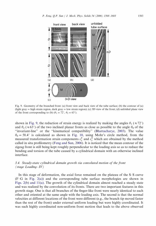
Fig. 9. Geometry of the branched front: (a) front view and back view of the tube surface; (b) the contour of (a)
(light gray ¼ high strain region, dark gray ¼ low strain region); (c) 3D view of the front; (d) unfolded plane view
of the front corresponding to (b) (y1 ¼ 721, y2 ¼ 631).
P. Feng, Q.P. Sun / J. Mech. Phys. Solids 54 (2006) 1568–1603 1583
shown in Fig. 9, the reduction of strain energy is realized by making the angles y1 (E721)and y2 (E631) of the two inclined planar fronts as close as possible to the angle y0 of the‘‘invariant-line’’ or the ‘‘kinematical compatibility’’ (Bhattacharye, 2003). The valuey0 ¼ 58.41 is calculated as shown in Fig. 10, using Mohr’s circle method, from themeasured transformation strain components eTx and eTy which are obtained by the methodcalled in situ profilometry (Feng and Sun, 2006). It is noticed that the mean contour of thezigzag front is still being kept roughly perpendicular to the loading axis so as to reduce thebending and torsion of the tube caused by a cylindrical domain with an otherwise inclinedinterface.
3.4. Steady-state cylindrical domain growth via convoluted motion of the front
(stage Loading– IV)
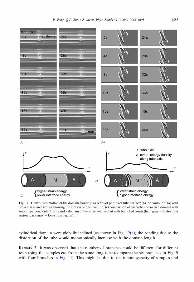
In this stage of deformation, the axial force remained on the plateau of the S–S curve(F–G in Fig. 2(a)) and the corresponding tube surface morphologies are shown inFigs. 2(b) and 11(a). The growth of the cylindrical domain almost reached a steady stateand was realized by the convolution of its fronts. There are two important features in thisgrowth stage. One is that all branches of the finger-like front were nearly identical to eachother and oriented at the same angle with the loading axis. The second is that the normalvelocities at different locations of the front were different (e.g., the branch tip moved fasterthan the rest of the front) under external uniform loading but were highly coordinated. Itwas such highly coordinated non-uniform front motion that leads to the above observed
ARTICLE IN PRESS
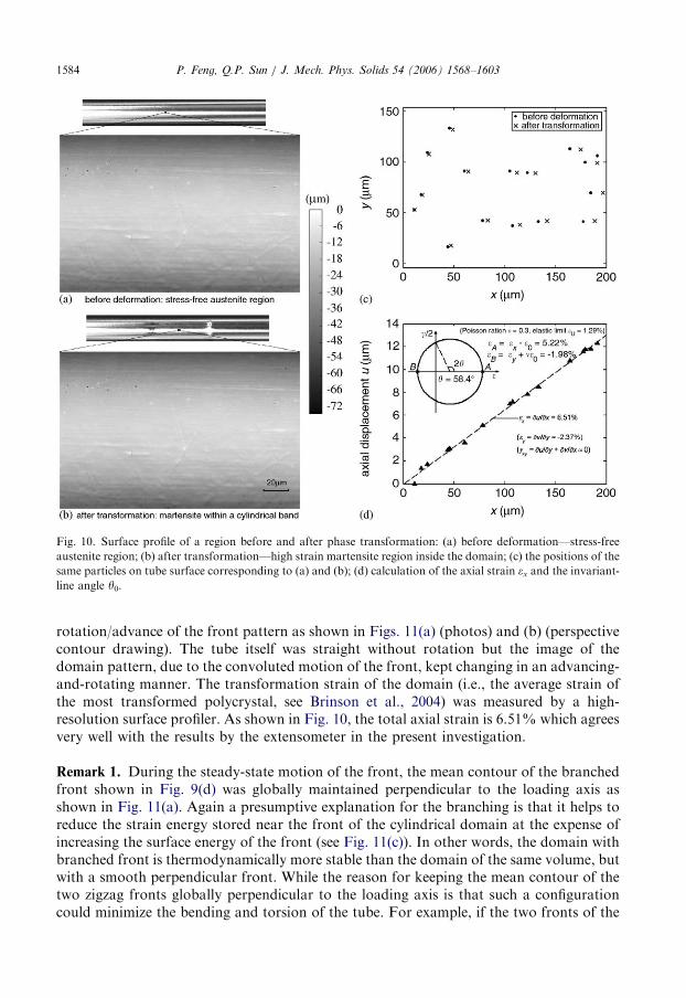
Fig. 10. Surface profile of a region before and after phase transformation: (a) before deformation—stress-free
austenite region; (b) after transformation—high strain martensite region inside the domain; (c) the positions of the
same particles on tube surface corresponding to (a) and (b); (d) calculation of the axial strain ex and the invariant-
line angle y0.
P. Feng, Q.P. Sun / J. Mech. Phys. Solids 54 (2006) 1568–16031584
rotation/advance of the front pattern as shown in Figs. 11(a) (photos) and (b) (perspectivecontour drawing). The tube itself was straight without rotation but the image of thedomain pattern, due to the convoluted motion of the front, kept changing in an advancing-and-rotating manner. The transformation strain of the domain (i.e., the average strain ofthe most transformed polycrystal, see Brinson et al., 2004) was measured by a high-resolution surface profiler. As shown in Fig. 10, the total axial strain is 6.51% which agreesvery well with the results by the extensometer in the present investigation.
Remark 1. During the steady-state motion of the front, the mean contour of the branchedfront shown in Fig. 9(d) was globally maintained perpendicular to the loading axis asshown in Fig. 11(a). Again a presumptive explanation for the branching is that it helps toreduce the strain energy stored near the front of the cylindrical domain at the expense ofincreasing the surface energy of the front (see Fig. 11(c)). In other words, the domain withbranched front is thermodynamically more stable than the domain of the same volume, butwith a smooth perpendicular front. While the reason for keeping the mean contour of thetwo zigzag fronts globally perpendicular to the loading axis is that such a configurationcould minimize the bending and torsion of the tube. For example, if the two fronts of the
ARTICLE IN PRESS
Fig. 11. Convoluted motion of the domain fronts: (a) a series of photos of tube surface; (b) the contour of (a) with
cross marks and arrows showing the motion of one front tip; (c) comparison of energetics between a domain with
smooth perpendicular fronts and a domain of the same volume, but with branched fronts (light gray ¼ high-strain
region, dark gray ¼ low-strain region).
P. Feng, Q.P. Sun / J. Mech. Phys. Solids 54 (2006) 1568–1603 1585
cylindrical domain were globally inclined (as shown in Fig. 12(a)) the bending due to thedistortion of the tube would monotonically increase with the domain length.
Remark 2. It was observed that the number of branches could be different for differenttests using the samples cut from the same long tube (compare the six branches in Fig. 9
with four branches in Fig. 11). This might be due to the inhomogeneity of samples and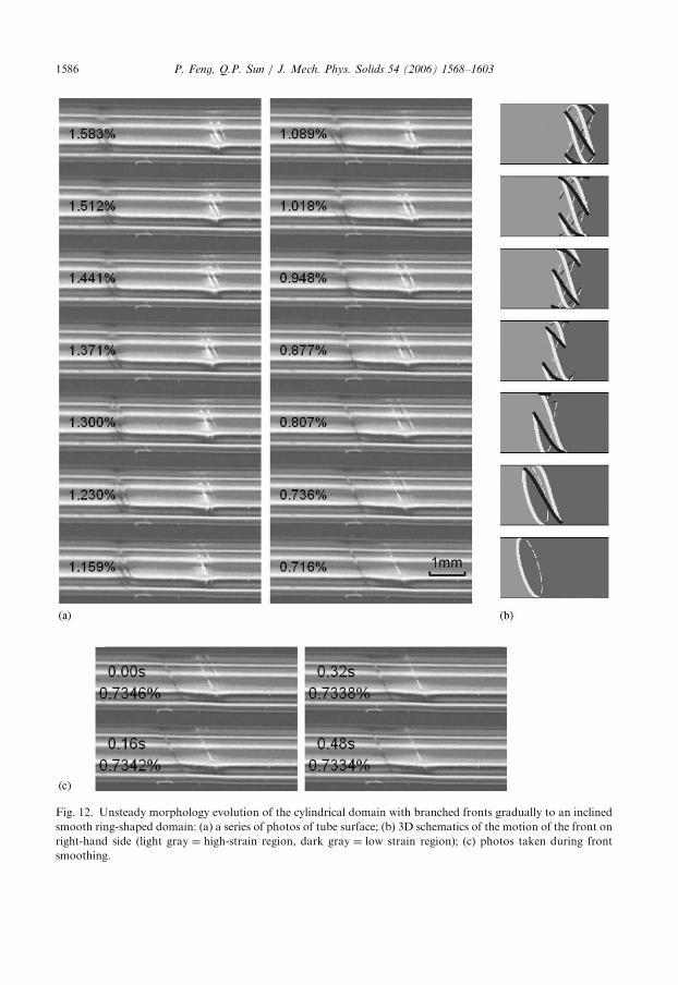
ARTICLE IN PRESS
Fig. 12. Unsteady morphology evolution of the cylindrical domain with branched fronts gradually to an inclined
smooth ring-shaped domain: (a) a series of photos of tube surface; (b) 3D schematics of the motion of the front on
right-hand side (light gray ¼ high-strain region, dark gray ¼ low strain region); (c) photos taken during front
smoothing.
P. Feng, Q.P. Sun / J. Mech. Phys. Solids 54 (2006) 1568–16031586
ARTICLE IN PRESSP. Feng, Q.P. Sun / J. Mech. Phys. Solids 54 (2006) 1568–1603 1587
needs to be clarified in future studies. Except the number of branches, all other aspects ofthe observed phenomena for different samples are the same.
Remark 3. Up to now, the domain morphology evolution during the loading process canbe summarized as the sequence of from the formation of helical domain with a smoothfront to its growth and front branching, then to the self-merging and formation of acylindrical domain by topology transition, and finally to the steady state growth of thecylinder-like domain by convoluted motion of the branched front while the mean contourof which is remained perpendicular to the loading axis. However, as will be shown below,the pattern evolution during unloading is not a simple reversal of those in the loadingprocess but exhibits a rather strong loading history dependence.
3.5. Reverse transition during unloading—reverse convolution and switching from branched
front to smooth front (Unloading-IV and III)
The unloading first led to an almost linear elastic response of the tube until the forcereached the lower stress plateau where reverse transition proceeded through the reverseconvolution of the front. The shrinkage of the domain was a gradual and stable processunder quasi-static unloading and took place at the lower stress plateau (about 205MPa).For the stage of Unloading-IV (I–K of Figs. 2(a) and (b)) the shrinkage was basically asimple reversal of that in loading. However, at the stage of Unloading-III two events wereobserved: one is the gradual inclination of the front followed by the front switching from abranched to a smooth one at a critical domain length; the other is the breaking of smoothring-like domain and dynamic domain vanishing which will be shown in Section 3.6.
Before the branched front switched to a smooth one, the branched front of thecylindrical domain had gradually become inclined during unloading (as shown in Fig.12(a)). When the domain length (i.e., the length along axial direction) was reduced toabout 1.10mm, the inclined branched front became unstable and switched to a smooth onedynamically through the fast retreat of the tips at a speed of the order of 10mm/s (see thelast two pictures in Figs. 12(a) and (c) of a higher time resolution). A series of schematicdrawings based on our observations on the evolution of a branched front into a smoothone are shown in Fig. 12(b). When in the form of a smooth inclined ring, the domaincontinued to shrink for a while during further unloading with its two fronts almostremaining parallel.
Remark 1. One mechanism responsible for the gradual inclination of the original globallyperpendicular front into a globally inclined one is the competition between the strainenergy and the energy due to the self-bending and self-torsion of the tube. As thecylindrical domain shrank and the domain length became shorter, the self-bending energydue to the inclined front was much reduced and the strain energy of the domain becameimportant and dominated the domain orientation, which made the branched front becomeglobally inclined. Both the strain energy and surface energy of the domain would besmaller than those of a domain with the same length but with branched and globallyperpendicular fronts.
Remark 2. The front switching could be explained as follows: as the axial length of theinclined cylinder-like domain became short (i.e. an inclined ring), the ratio of the surfaceenergy over the strain energy became large so that the surface energy dominated the
ARTICLE IN PRESSP. Feng, Q.P. Sun / J. Mech. Phys. Solids 54 (2006) 1568–16031588
morphology. This made the branched front switch to a smooth one so as to reduce thesurface energy.
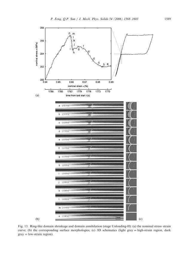
3.6. Ring-like domain breaking and dynamic annihilation (stages Unloading-I and II)
Further unloading led the reverse transformation process to completion through twosub-stages: the breaking of the smooth ring-like domain into a C-shaped inclusionby topology transition and dynamic annihilation of this C-shaped domain, as shown inFig. 13.The first sub-stage ring-like domain shrinkage was accompanied by a gradual load
increase until the domain was ‘‘broken’’ into a C-shaped inclusion (see b–f of Fig. 13). Thedeformation of this stage was stable and can be controlled. It was noticed that the frontorientation varied along the ring-like domain front and the domain shrank non-uniformly.For the given elongation (unloading) rate, when the domain length was reduced to below0.71mm (see point b) its shrinkage was accelerated, and this caused a small but obviousstress increase (see b–f in Figs. 13(a)). It seemed that, like the attraction in self-mergingduring loading, an attraction force emerged on the two fronts when the distance betweenthe two fronts reached a certain value. It was this attractive force that caused theaccelerated shrinkage. This eventually led to the topology transition changing the ring-likedomain into a C-shaped inclusion with an aspect ratio of about 20 (5.4mm length/0.26mmwidth, see f in Figs. 13(b) and (c)) (refer to the movie on the website http://www-mech.ust.hk/�meqpsun/).In the second sub-stage the C-shaped domain further shortened and thinned with load
fluctuations for a short period (f–h in Fig. 13(a)), then shrank dynamically by fast frontretreat and eventually vanished as shown by both the very steep load rise (see h–n inFig. 13(a) and the surface images in (b) and (c)). After the domain annihilation, the matrix(austenite phase) deformed linearly for the rest of the unloading process and the S–S curvealmost coincided with that of the loading process.
Remark 1. It was found that the magnified S–S curve during the domain breaking andvanishing is similar but opposite to that of domain nucleation in Fig. 2 during loadingexcept that the former is on a much lower stress level. The typical domain size and loadjump are also much less distinct (a smaller jump of 3MPa in nominal stress during domainannihilation compared with a large drop of 15MPa during nucleation). Again, thecompetition between the domain front energy and strain energy played an important rolein the domain morphology evolution of this stage.
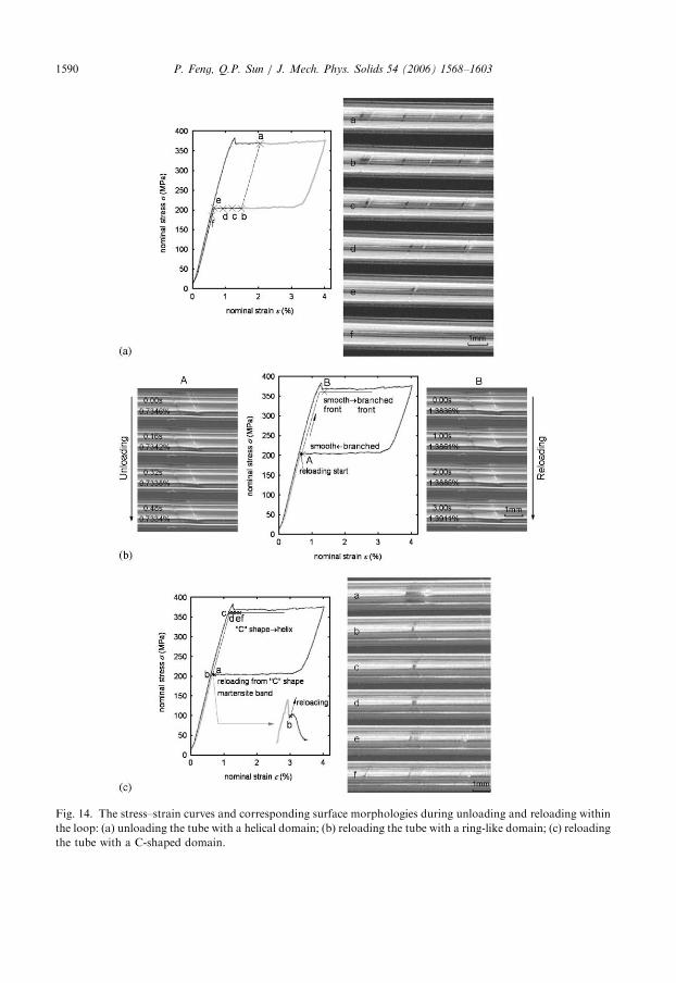
3.7. Path dependence of patterns during unloading and reloading within the loop
It is worth checking the morphology and response of the tube for the unloading andreloading processes within the loop. Strong loading path dependence of the tubemorphology was found and they are only briefly summarized as follows.If the tube was unloaded before the domain growth reached its steady state where the
mean contour of the branched front became perpendicular to the loading axis, the domainmorphology was found to be reversible, i.e. the domain would evolve back to a helix ratherthan to a ring (Fig. 14(a)).
ARTICLE IN PRESS
Fig. 13. Ring-like domain shrinkage and domain annihilation (stage Unloading-II): (a) the nominal stress–strain
curve; (b) the corresponding surface morphologies; (c) 3D schematics (light gray ¼ high-strain region, dark
gray ¼ low-strain region).
P. Feng, Q.P. Sun / J. Mech. Phys. Solids 54 (2006) 1568–1603 1589
ARTICLE IN PRESS
Fig. 14. The stress–strain curves and corresponding surface morphologies during unloading and reloading within
the loop: (a) unloading the tube with a helical domain; (b) reloading the tube with a ring-like domain; (c) reloading
the tube with a C-shaped domain.
P. Feng, Q.P. Sun / J. Mech. Phys. Solids 54 (2006) 1568–16031590
ARTICLE IN PRESSP. Feng, Q.P. Sun / J. Mech. Phys. Solids 54 (2006) 1568–1603 1591
If the tube was unloaded after the domain growth reached its steady state, it can be seenclearly in Section 3.5 that during unloading the cylindrical domain would not reversiblyevolve back to the helical domain, instead, it would evolve to the inclined smooth ring-likedomain (also see Figs. 12 and 13). If the tube with such a ring-like domain was reloaded tothe upper stress plateau, the domain would first grow in a stable manner and then itssmooth front branched macroscopically at the length of 1.20mm which was a little largerthan that for unloading (E1.10mm), see Fig. 14(b).
If the tube with a C-shaped domain (see h–m of Fig. 13) was reloaded to the upper stressplateau, the C shape would not heal up to its original ring. Instead, it would grow into ahelical domain along one of its more favored tip direction at an orientation of about 601 asshown in Fig. 14(c), while the other energetically less favored tip would serve as a kind ofdefect which basically does not influence the helical growth and would eventually beengulfed by the helical domain.
We would like to end this section by emphasizing the important influence ofstructure–material coupling in the above domain evolution. Such coupling, in the formof the created torsion and bending in the tube, is unavoidable during the tube elongation.For example, the asymmetric domain patterns either at the initial domain formation or atthe subsequent domain growth will lead to an asymmetric torsion and bending in the tube,which in turn will influence the domain pattern and evolution. Though the whole process isstill dominated by tension for the thin-walled long tube, transformation under axialstretching would simultaneously produce torque and a bending moment in the tube. Bothare expected to vary with domain growth and be detected. In the present research specialattention was paid to the torque response during stretching. However, the measurement ofsuch a small torque has not been successful in the experiment because of the considerablylow-torsion rigidity of the thin-walled long microtubing. This data gap will be filled bycontinued effort in the future.
4. Discussions of the experimental results
From the results of Section 3, we can see that there are basically two types of instabilityevents which took place during the transformation process of the tube. One is theinstability of a homogeneous deformation, which leads to the phenomenon of domainnucleation and vice versa, domain annihilation (see Figs. 4 and 13, h–n). The otheris the instability of the existing domain wall, which leads to interface branching anddomain morphology transition (see Figs. (8), (9), (12) and (13), a–g). Both events aredynamic (i.e. in an uncontrollable manner) even under extremely small nominal strain rateand they both occupy distinctly much shorter time spans than that of the stablepropagation of the front (notice the time coordinates in the figures mentioned above). If weexamine further the stable propagation of the macroscopic front with even higher spatialand time resolutions, it would again contain numerous distinct and successive micro-instabilities associated with the nucleation, annihilation and switching of microscaledomains inside individual grains in the narrow frontal zone. Such multi-scalespatiotemporal scenario of the deformation process reflects the intrinsic discrete naturesof the material hierarchy of the polycrystal. Therefore the above processes are alldissipative and are governed by different kinetics of the material. They will be discussed inthe following.
ARTICLE IN PRESSP. Feng, Q.P. Sun / J. Mech. Phys. Solids 54 (2006) 1568–16031592
4.1. Physical origin of the macroscopic deformation instability in polycrystals
For the first type of instability (instability of the homogeneous deformation), it is seenfrom Fig. 2 that before the macroscopic domain nucleation the loading curve exhibitedsmall nonlinearity due to the formation of many microscopic martensite bands in thepolycrystal, but the macroscopic deformation is still homogeneous. Such small scaletransformation is evidenced by both the small hysteresis loop upon unloading (see Fig. 3)before the peak load and the uniform temperature increase of about 0.2 1C at the samplesurface. This homogeneous deformation (here termed as pre-burst incubation) persisteduntil the peak load that marks the beginning of macroscopic burst transformation. Thepre-burst (macroscopically stable) and burst-like (autocatalytic) transformations (asdescribed in sub-stages (i)–(iii) in detail in Section 3.2) are typical of fine grained NiTipolycrystals in tension (see Li and Sun, 2002, Sun and Li, 2002 for microtubes; Shaw andKyriakides, 1995, 1997 and Sun et al., 2001 for strips and wires). They were also observedin the transformation of other systems (see Nishyama, 1978; Reyes-Morel and Chen, 1988;Rose and Swain, 1988 for ceramics; and Yu and Clapp, 1989 for metals, among others).They were discussed in the literature using various terminologies such as autocatalyticeffect, burst, avalanche, chain reaction, percolation, etc.There are two explanations for the possible physical mechanisms of the macroscopic
deformation instability shown in Fig. 2. One speculated mechanism is the autocatalyticnucleation and coalescence of many micro-martensite bands or variants inside very smallgrains of the NiTi polycrystal. The autocatalytic transformation happened because theinteraction among the local stress fields of these micro-domains formed in the pre-burststage become increasingly strong with loading and eventually these micro-events percolateup to the macroscopic level and lead to the strain softening of a macroscopic representativematerial element until it is fully transformed. The phenomenon of autocatalysis, wherein aregion of elastic phase transformation creates stresses sufficient to drive alone furthertransformations, was identified long time ago in the material systems mentioned above. Inreal polycrystals there is always a competition between the softening mechanism and thehardening mechanism (e.g. due to grain orientation) in the overall behavior. It is stronglyinfluenced by the detailed microstructure (e.g. texture and grain size distribution) and thestress state (e.g. tension, shear or compression). In terms of elasticity, the softeningstress–strain relation corresponds to a macroscopic non-convex strain energy function ofthe material during phase transition. Another possible mechanism leading to themacroscopic band formation, without invoking the intrinsic material softening, is thegeometric instability due to the finite transformation strain. This is similar to the neckformation observed in some polymers where the material’s true stress–strain relation is stillstable. The investigation on this type of localized deformation has been well documented inthe literature (see review articles by Needleman and Tvergaard, 1992; Nguyen, 1994;Tomita, 1994; Petryk, 1997 and the large number of references therein). Either geometricinstability (for NiTi, see Orgeas and Favier, 1998; Favier et al., 2001; Sittner et al., 2005) ormaterial instability (Falk, 1980, 1982, 1983; Barsch and Krumhansl, 1988; Abeyaratne etal., 2002), it is usually not straight forward from the measured nominal S–S curve to seeimmediately which one is dominant for the domain formation in the NiTi polycrystal.According to some micromechanical models (Roitburd, 1973; Sun et al., 1991; Sun and
Hwang, 1993; Bruno et al., 1995; Smyshlyaev and Willis, 1998) the elastic energy of atransforming polycrystal can be non-convex (softening stress–strain relation) for certain
ARTICLE IN PRESSP. Feng, Q.P. Sun / J. Mech. Phys. Solids 54 (2006) 1568–1603 1593
types of microstructures. One of the simplest form of non-convex energy is the Af(1– f)type, where A is a constant, f is the volume fraction of a cluster of small spherical (circularin 2D) martensite variant for fine grained polycrystal. The material used in this paper isindeed extra-fine grained polycrystal (grain size of 50–100 nm). Another argumentsupporting the strain softening in tension is the measured value of load drop duringmacroscopic domain formation. It has been shown (Shaw and Kyriakides, 1998) thatgeometric instability alone (due to the finite 5% transformation strain of the domain) canonly cause a relatively small load drop. Using the values of modulus and strains from thetube, the maximum allowable load drop due to geometric instability (with stable tri-linearstress–strain relation) is only about 23.4MPa, which is much less than the experimentalobservation of 42–90MPa (Tse and Sun, 2000; Li, 2002). The non-convexity of strainenergy function for the polycrystal is also supported by recent finite element simulation(He and Sun, 2005) on domain morphology in NiTi tube. The results indicated that onlygeometry effect is not sufficient to quantify the experimental observation and that materialinstability dominates the observed helical domain formation.
There have been notable theoretical efforts in recent years to model the nucleation peak,propagation plateau and hysteresis phenomena, emphasizing the discreteness andnonlocality of the phase transition process (see Abeyaratne et al., 1996; James, 1996;Ortin and Delaey, 2002; Triantafyllidis and Bardenhagen, 1993; Truskinovsky andVainchtein, 2004 and the references therein). The present observations appear to beconsistent to such a picture that microscopic instability developed at the macroscopichomogeneous deformation stage and continues after the macroscopic system becomesunstable. More detailed systematic measurement and quantitative modeling for realpolycrystals along this line of thought remain to be conducted in the future.
4.2. Macroscopic domain wall energy and its role in morphology evolution
For the second type of instability (instability of the domain wall), it is basicallyattributed to the differences in the total energy (bulk strain energy and interfacial energy)among the possible states of domains in tube system. Such difference leads to morphologytransition. It bares lots of similarities with the morphological instabilities in other solidsystems (for example, see Srolovitz, 1989; Suo, 1997). Here, the existence of macroscopicdomain wall energy (interfacial or front energy) and its role in the formation and evolutionof domains are strongly indicated by the present research. Although the idea of energyassociated with the macroscopic transformation front is not new, it is almost completelyomitted in the previous research on instability of polycrystalline NiTi. For the purpose ofsimplicity, we purposely treat the domain structure as the minimizer of free energy of theactually dissipative. According to such equilibrium frame work the domain formation andevolution in the tube configuration can be understood as follows.
First, it is seen that the formation and growth of the helical domain broke the symmetryof axial loading and axial symmetric tube geometry. This symmetry-breaking morphology
and its subsequent evolution could be attributed to the energy preference among ‘‘possibleequilibrium shapes’’ of a domain inside which the transformation strain is shear in nature.The difference in the dependence on domain size of bulk energy (such as elastic strainenergy) and the domain wall energy will make the equilibrium domain shape also size-dependent (Johnson and Cahn, 1984; Jog et al., 2000; Voorhees and Johnson, 2004).For example, during the nucleation of the macroscopic helical domain the energy of the
ARTICLE IN PRESSP. Feng, Q.P. Sun / J. Mech. Phys. Solids 54 (2006) 1568–16031594
domain wall played an important role for the finite aspect ratio of the domain, otherwiseits shape would be unrealistically long and narrow. The domain self-merging duringloading and annihilation during unloading could also be understood according to suchinterplay between the two energies. When the two fronts come close enough the drivingforce from the rapid reduction in the interfacial energy of the system accelerated the frontmerge, producing an obvious load change in the S–S curve. The role of front energymanifested again during the formation of the branched front and front smoothing.Second, the competition between bulk and interfacial energies during unloading/
reloading can lead to branched ring 2 smooth ring and smooth ring 2 inclusiontopology transitions. It is noticed that the helix (a lenticular inclusion once flattened) andring (inclined narrow cylinder) are the two basic, but topologically different forms of thedomain in the tube configuration. The ring-like domain is sandwiched by the two separatedaustenite (lower strain phase) while the helical band is a single inclusion embedded in theaustenite. Compared with the cylindrical domain of the same volume, the helix hasrelatively larger interface area, but has much less elastic strain energy. Therefore, tominimize the total energy, a helical domain is preferred to form when the interfacial energydensity is relatively small, while a ring domain is preferred to form when the interfacialenergy density is relatively large (see Ng and Sun, 2006). From thermodynamics point ofview, the reported topology transition and its loading path dependence reflect themultiplicity of metastable domains in the tube configuration.Third, regarding the physical nature of the macroscopic scale domain wall energy in
polycrystal, it is very similar to the energy of the interface (habit plane) between austeniteand twinned martensite in single crystal due to local incompatibility (Fig. 15(a)) (amongmany literatures, see Khachaturyan, 1983; Roitburd, 1998 and recently Maciejewski et al.,2005). One of the key complexities in quantifying this energy is the hierarchy of themacroscopic domain wall in polycrystal as shown in Fig 15(b). It is seen that amacroscopically compatible ‘‘sharp’’ front, after zoom in, is in fact a very incompatiblezone containing many differently oriented grains and micro-domains. The local stress fieldof this interfacial zone is highly non-uniform. It is also seen that for the nano-grainedpolycrystal of this paper, the domain wall thickness lp should be much smaller than thevalue measured by surface profiler in Fig. 6. Experimental study to quantify the value of lpis currently under way. For a pure phenomenological purpose, the front energy could beestimated by fitting the morphology data with the calculation using the nonlocal andnonconvex framework (Cahn and Hilliard, 1958; Falk, 1983).We should finally emphasize that the interaction between material and structure
geometry always exists and sometimes even strongly influences the observed phenomena ofmorphology evolution in the tube system through the created torque and bending moment.A quantitative account of this aspect will rely on future modeling and simulation.
4.3. Mobility of the front and heat effect during domain pattern evolution
In the present tube configuration a single helical domain could survive and grow afternucleation so that a nominal stress and front velocity relationship could be obtained. Thismeasured relationship captured the macroscopic effect of those micro-thermomechanicalevents which facilitated the macroscopic front motion in polycrystals (Abeyaratne andKnowles, 1990, 1997). Usually a front kinetics expressed as V ¼ V(F), relating the frontvelocity V and the thermodynamic driving force F at the front, is supposed to exist and is

ARTICLE IN PRESS
Fig. 15. Multi-scale structure of the austenite–martensite interface (front zone) and the material hierarchy therein
(a) interface and interface energy in single crystal; (b) domain and domain energy in polycrystal tube (light
gray ¼ high-strain region, dark gray ¼ low-strain region).
P. Feng, Q.P. Sun / J. Mech. Phys. Solids 54 (2006) 1568–1603 1595
proposed as an intrinsic constitutive function of the material. Under an externally appliedstress the driving force of the front can be calculated. In tube configuration the fastergrowth of the initial domain at the tip than that in transverse direction turned the domaininto a helical shape. In extracting the isothermal front kinetics V ¼ V(F) from themeasured data the heat effect which results from generation, conduction and convection oflatent heat must be carefully taken into account.
It is known that the latent heat generated as the front propagates during A-Mtransition will reduce the chemical driving force, so the front velocity is limited by heattransfer. At the same time, as the domain grows, the resulted load drop will also reduce the
ARTICLE IN PRESSP. Feng, Q.P. Sun / J. Mech. Phys. Solids 54 (2006) 1568–16031596
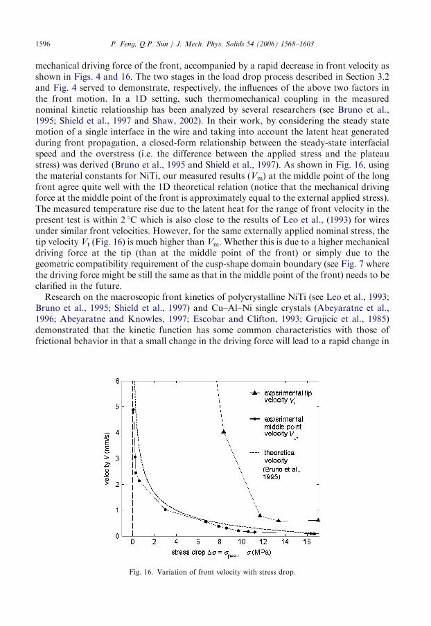
mechanical driving force of the front, accompanied by a rapid decrease in front velocity asshown in Figs. 4 and 16. The two stages in the load drop process described in Section 3.2and Fig. 4 served to demonstrate, respectively, the influences of the above two factors inthe front motion. In a 1D setting, such thermomechanical coupling in the measurednominal kinetic relationship has been analyzed by several researchers (see Bruno et al.,1995; Shield et al., 1997 and Shaw, 2002). In their work, by considering the steady statemotion of a single interface in the wire and taking into account the latent heat generatedduring front propagation, a closed-form relationship between the steady-state interfacialspeed and the overstress (i.e. the difference between the applied stress and the plateaustress) was derived (Bruno et al., 1995 and Shield et al., 1997). As shown in Fig. 16, usingthe material constants for NiTi, our measured results (Vm) at the middle point of the longfront agree quite well with the 1D theoretical relation (notice that the mechanical drivingforce at the middle point of the front is approximately equal to the external applied stress).The measured temperature rise due to the latent heat for the range of front velocity in thepresent test is within 2 1C which is also close to the results of Leo et al., (1993) for wiresunder similar front velocities. However, for the same externally applied nominal stress, thetip velocity Vt (Fig. 16) is much higher than Vm. Whether this is due to a higher mechanicaldriving force at the tip (than at the middle point of the front) or simply due to thegeometric compatibility requirement of the cusp-shape domain boundary (see Fig. 7 wherethe driving force might be still the same as that in the middle point of the front) needs to beclarified in the future.Research on the macroscopic front kinetics of polycrystalline NiTi (see Leo et al., 1993;
Bruno et al., 1995; Shield et al., 1997) and Cu–Al–Ni single crystals (Abeyaratne et al.,1996; Abeyaratne and Knowles, 1997; Escobar and Clifton, 1993; Grujicic et al., 1985)demonstrated that the kinetic function has some common characteristics with those offrictional behavior in that a small change in the driving force will lead to a rapid change in
Fig. 16. Variation of front velocity with stress drop.
ARTICLE IN PRESS
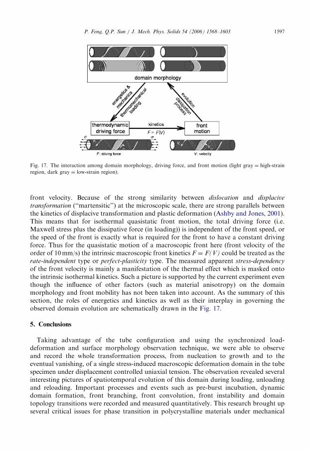
Fig. 17. The interaction among domain morphology, driving force, and front motion (light gray ¼ high-strain
region, dark gray ¼ low-strain region).
P. Feng, Q.P. Sun / J. Mech. Phys. Solids 54 (2006) 1568–1603 1597
front velocity. Because of the strong similarity between dislocation and displacive
transformation (‘‘martensitic’’) at the microscopic scale, there are strong parallels betweenthe kinetics of displacive transformation and plastic deformation (Ashby and Jones, 2001).This means that for isothermal quasistatic front motion, the total driving force (i.e.Maxwell stress plus the dissipative force (in loading)) is independent of the front speed, orthe speed of the front is exactly what is required for the front to have a constant drivingforce. Thus for the quasistatic motion of a macroscopic front here (front velocity of theorder of 10mm/s) the intrinsic macroscopic front kinetics F ¼ F(V) could be treated as therate-independent type or perfect-plasticity type. The measured apparent stress-dependency
of the front velocity is mainly a manifestation of the thermal effect which is masked ontothe intrinsic isothermal kinetics. Such a picture is supported by the current experiment eventhough the influence of other factors (such as material anisotropy) on the domainmorphology and front mobility has not been taken into account. As the summary of thissection, the roles of energetics and kinetics as well as their interplay in governing theobserved domain evolution are schematically drawn in the Fig. 17.
5. Conclusions
Taking advantage of the tube configuration and using the synchronized load-deformation and surface morphology observation technique, we were able to observeand record the whole transformation process, from nucleation to growth and to theeventual vanishing, of a single stress-induced macroscopic deformation domain in the tubespecimen under displacement controlled uniaxial tension. The observation revealed severalinteresting pictures of spatiotemporal evolution of this domain during loading, unloadingand reloading. Important processes and events such as pre-burst incubation, dynamicdomain formation, front branching, front convolution, front instability and domaintopology transitions were recorded and measured quantitatively. This research brought upseveral critical issues for phase transition in polycrystalline materials under mechanical
ARTICLE IN PRESSP. Feng, Q.P. Sun / J. Mech. Phys. Solids 54 (2006) 1568–16031598
forces. The underlying physical mechanisms and the related modeling aspects have beendiscussed. Some of them can be understood readily but others are still quite vague orspeculative and need further investigation. The conclusions of the paper are listed asfollows:
�
The domain morphology evolution during the loading process can be summarized asthe sequence of from the dynamic formation of the helical domain to its further growthand its front branching, then to the self-merging and topology transition into acylindrical domain, and finally to the stable growth of the cylinder-like domain by theconvoluted motion of its branched front. � The domain pattern evolution during unloading is not a simple reversal of that in theloading process but exhibits rather strong loading history dependence. For monotonicunloading the pattern evolution is basically via the sequence of from the reverseconvolution of the branched front to the switching into smooth front, and then todomain breaking and eventually to dynamic domain annihilation.
� Even under the extremely small nominal strain rate, the phase transition process stillinvolves both macroscopic static (such as stable growth of domain with very slow frontmotion) and macroscopic dynamic events (such as front branching/smoothing anddomain formation/merging/annihilation). The whole deformation period is divided intotwo distinct macroscopic time spans associated with the stable propagation andunstable macroscopic front propagation, respectively. The latter is much shorter thanthe former. The former, if looked with even higher resolution, would be again realizedthrough the numerous successive microscale nucleations, growth and switching insidethe macroscopic frontal zone. The macroscopic part of this multi-scale process in thepolycrystalline material is observed in the present experiment.
� The analysis of the observed phenomena in tube configuration clearly reveals that thecompetition between the macroscopic domain wall energy and the bulk energy playedan important role in domain morphology evolution. The origin of the domain wallenergy is attributed to the intrinsic heterostructures of the polycrystal. The domain wallthickness and the effective wall energy are expected to be proportional to thecharacteristic length of the heterostructures. Quantifying this energy term inpolycrystalline materials remain open for future investigation.
� The velocity of the front during dynamic domain formation is measured directly in theexperiment. The obtained nominal overstress and front speed relationship supports theisothermal rate-independent or perfect-plasticity type kinetics for the quasistatic frontmotion. Such relationship also agrees with the previous theoretical model predictionwhich is based on a one-dimensional setting taking the heat transfer effect intoconsideration. It is the combined effort of kinetic law and energetic preference thatgoverns the various observed aspects of domain formation and evolution.
Acknowledgments
The authors are grateful for the financial support from the Research Grants Council ofthe Hong Kong SAR, China (through Projects HKUST 6234/01E, HKUST 6245/02E andHKUST 6156/04E). QPS is grateful to the French Ministry of Education for financing avisit at LMT (CNRS) of Ecole Normale Superieure de Cachan in Paris hosted by Prof.Han Zhao. He also would like to thank Prof. K. Bhattacharya of the California Institute of
ARTICLE IN PRESSP. Feng, Q.P. Sun / J. Mech. Phys. Solids 54 (2006) 1568–1603 1599
Technology, Prof. S. Kyriakides of the University of Texas at Austin and Prof. H. Petrykof IPPT of the Polish Academy of Science for the stimulating discussions on the results ofthis paper.
Appendix A. Four subsystems of the developed testing system
The testing of microtubing requires a series of careful and precise operations, such asmeasurement under a large twist up to 7201, microscopy and profilometry to quantifysurface morphology, high-speed data acquisition for the dynamic domain formation, andsynchronized recording of load response and surface images, etc. These operations are notsupported by the existing universal testing machine system, so it is necessary to develop atesting system suitable for NiTi microtubing. The testing system is mainly made up of foursubsystems: the loading subsystem, measurement subsystem, surface observationsubsystem and automation subsystem.
The loading subsystem is designed to apply a controlled loading to the tubing specimen.A stepping motor (HS2221, MAE, Italy) is installed to drive the system. Controlled by amicrostepping drive (IM804, IMS, USA), the motor can run with a rotary angle resolutionas small as 0.0071. The speed can be as slow as 0.001 rpm, corresponding to an elongationrate of 5 mm/min of the specimen when a ball screw with 5mm lead (RNFTL1405A2.5Sand RS1405A5, NSK, Japan) is used to transform the rotation into linear motion. This isideal for quasi-static loading. The drive is connected to a computer with a motion controlcard (DMC1000, Leisai, China) which makes automatic and programmable loadingpossible. Thus, the motor can provide a smooth load in a controlled and quasi-static way.Tube grips are used to fix the two ends of the specimen. The friction between the grip andthe specimen is large enough to guarantee that there is no sliding between them.
The measurement subsystem is to measure the nominal strains and stresses of thespecimen. A combined sensor was designed by the authors and manufactured by acompany (TML, Japan). In the alternative solution, a load cell (445N, 2308-01A, PCB,USA) and a torque sensor (0.57N/m, 1538-01A, PCB, USA) are employed. There are twostrain measurement configurations (see Feng, 2005). In the single-sided configuration, onegrip is fixed; the axial motion of the other grip is measured by a cantilever sensor (CE-5,TML, Japan) whose tip is in contact with the bottom of the grip; the rotary motion ismeasured by a dial sensor (DDP-30A, TML, Japan) whose tip is in contact with the wingplate fixed on the side of the grip. In the double-sided configuration, one grip isconstrained against axial motion but free to rotate and the other is constrained againstrotation but free to conduct axial motion; the installation of the sensors is similar.
The surface observation subsystem is to observe the surface of specimens. An imagingcamera (TK-C1381EG, JVC, Japan with telescopic lens Zoom 7000, Navitar, USA) isemployed to directly observe the surface morphology (such as high-strain domain shapeand orientation, etc.) of the tube during loading and unloading. A microscope (zoomstereo, SZH-10, Olympus, Japan with digital camera Coolpix 4500, Nikon, Japan) isemployed to obtain more detail of the surface morphology. A high speed motion camera(8000 fps max., Motion Scope PCI, Redlake, USA) is used to capture the moment ofdomain formation. It should be emphasized that lighting is essential to obtain high qualityimages. A profiler (vertical resolutiono0.3 nm, NT3300, Wyko, USA) is used to quantifythe in-plane and out-of-plane surface displacement and therefore the correspondingstrains. An infra-red camera (PM695, FLIR, USA) is employed to evaluate the
ARTICLE IN PRESSP. Feng, Q.P. Sun / J. Mech. Phys. Solids 54 (2006) 1568–16031600
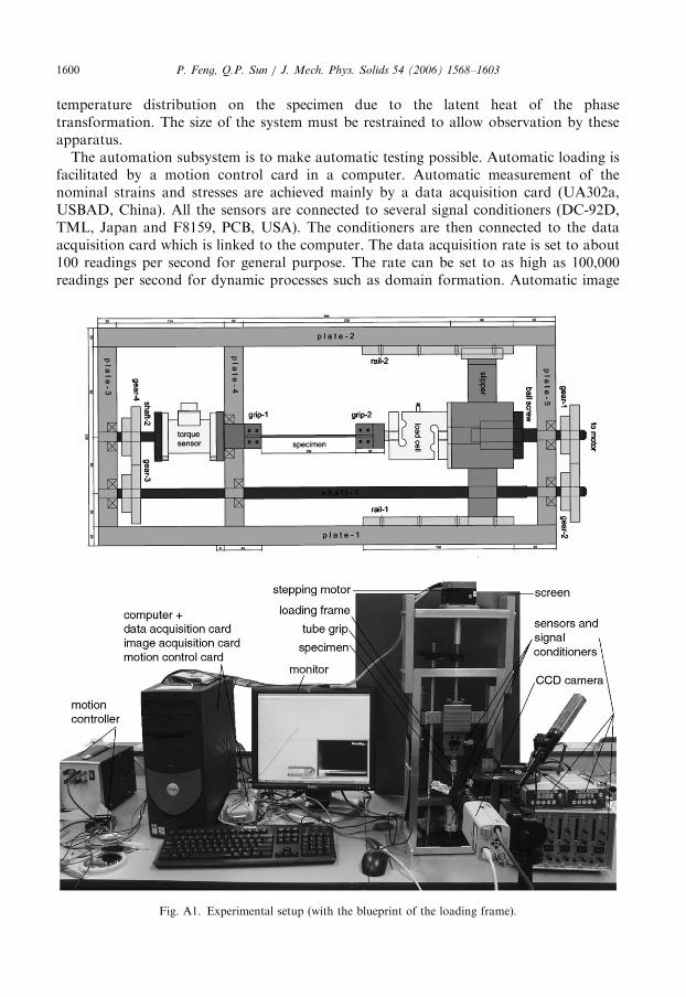
temperature distribution on the specimen due to the latent heat of the phasetransformation. The size of the system must be restrained to allow observation by theseapparatus.The automation subsystem is to make automatic testing possible. Automatic loading is
facilitated by a motion control card in a computer. Automatic measurement of thenominal strains and stresses are achieved mainly by a data acquisition card (UA302a,USBAD, China). All the sensors are connected to several signal conditioners (DC-92D,TML, Japan and F8159, PCB, USA). The conditioners are then connected to the dataacquisition card which is linked to the computer. The data acquisition rate is set to about100 readings per second for general purpose. The rate can be set to as high as 100,000readings per second for dynamic processes such as domain formation. Automatic image
Fig. A1. Experimental setup (with the blueprint of the loading frame).
ARTICLE IN PRESSP. Feng, Q.P. Sun / J. Mech. Phys. Solids 54 (2006) 1568–1603 1601
acquisition from the imaging device of the observation subsystem is realized by a multi-function display card (Winfast A310 TD VIVO, Leadtek, Taiwan) in the computer.Software is written by the authors to define the loading process, to display the stress-straincurve and the morphology in real time, to synchronize data and image acquisition, todefine data acquisition process, etc. A complete system is shown in Fig. A.1.
References
Abeyaratne, R., Knowles, J.K., 1990. On the driving traction acting on a surface of discontinuity in a continuum.
J. Mech. Phys. Solids 40, 345–360.
Abeyaratne, R., Knowles, J.K., 1997. On the kinetics of an austenite-martensite phase transformation induced
by impact in a Cu–Al–Ni shape-memory alloy. Acta Mater. 45, 1671–1683.
Abeyaratne, R., Chu, C., James, R.D., 1996. Kinetics of materials with wiggly energies: theory and application to
the evolution of twinning microstructures in a Cu–Al–Ni shape memory alloy. Philos. Mag. A 73, 457–497.
Abeyaratne, R., Bhattacharya, K., Knowles, J.K., 2002. In: Fu, Y., Ogeden, R.W. (Eds.), Nonlinear Elasticity:
Theory and applications. Cambridge University Press, Cambridge, pp. 433–490.
Ashby, M.F., Jones, D.R.H., 2001. Engineering Materials 2, second ed. Butterworths, Heinemann, London.
Barsch, G.R., Krumhansl, J.A., 1988. Nonlinear and nonlocal continuum model of transformation precursors in
martensites. Metall. Trans. A 19, 761–775.
Bhattacharye, K., 2003. Microstructure of Martensite. Oxford University Press, Oxford.
Bhattacharye, K., Conti, S., Zanzotto, G., Zimmer, J., 2004. Crystal symmetry and the reversibility of martensitic
transformations. Nature 428, 55–59.
Berg, B., 1997. Twist and Stretch: Combined Loading of Pseudoelastic NiTi Tubing. In: Pelton, A.R., Hodgson,
D.E., Russell, M., Duerig, T.W. (Eds.), Proceedings of the Shape Memory and Superelastic Technologies
1997, pp. 443–448.
Brinson, L.C., Schmidt, I., Lammering, R., 2004. Stress-induced transformation behavior of a polycrystalline
NiTi shape memory alloy: micro and macromechanical investigations via in situ optical microscopy. J. Mech.
Phys. Solids 52, 1549–1571.
Bruno, O.P., Leo, P.H., Reitich, F., 1995. Free boundary conditions at austenite–martensite interfaces. Phys. Rev.
Lett. 74, 746–749.
Cahn, J.W., Hilliard, J.E., 1958. Free energy of a nonuniform system I. Interfacial energy. J. Chem. Phys. 28 (2),
258–267.
Escobar, J.C., Clifton, R.J., 1993. On pressure-shear plate impact for studying the kinetics of stress-induced phase
transformations. Mater. Sci. Eng. A 170, 125–142.
Falk, F., 1980. Model free-energy, mechanics and thermodynamics of shape memory alloys. Acta Metall. 28,
1773–1780.
Falk, F., 1982. Landau theory of martensitic phase transitions. J. Phys. IV, C4 43, 3–15.
Falk, F., 1983. Ginzburg–Landau theory of static domain-walls in shape-memory alloys. Z. Phys B—Condens.
Matter 51, 177–185.
Favier, D., Liu, Y., Orgeas, L., Rio, R., 2001. In: Sun, Q.P. (Ed.), Solid Mechanics and Its Applications, vol. 101.
Kluwer Academic Publisher, New York, pp. 205–212.
Feng, P., 2005. Ph.D. Thesis, Hong Kong University of Science and Technology, Hong Kong.
Feng, P., Sun, Q.P., 2006. Identification and measurement of the domain strain in NiTi microtubing under biaxial
loading. Smart Mater. Struct., in press.
Gruijicic, M., Olson, B.B., Owen, W.S., 1985. Mobility of the b1-g10 martensite interface in Cu–Al–Ni: Part I.
experimental measurements. Metall. Trans. A 16, 1723–1734.
He, Y.J., Sun, Q.P., 2005. Proceedings of the International Conference on Solid–Solid Phase Transformations in
Inorganic Materials, May 29–June 3, 2005. Phoenix, Arizona, USA.
James, R.D., 1996. Wiggly Energies. The Symposium in honor of J.L. Ericksen, June 12–14. Maryland, USA.
Jog, C.S., Sankarasubramanian, R., Abinandanan, T.A., 2000. Symmetry-breaking transitions in equilibrium
shapes of coherent precipitates. J. Mech. Phys. Solids 48, 2362–2389.
Johnson, W.C., Cahn, J.W., 1984. Elastically induced shape bifurcations of inclusions. Acta Metall. 32,
1925–1933.
Khachaturyan, A.G., 1983. Theory of Structure Transformation in Solids. Wiley, New York.
ARTICLE IN PRESSP. Feng, Q.P. Sun / J. Mech. Phys. Solids 54 (2006) 1568–16031602
Leo, P.H., Shield, T.W., Bruno, O.P., 1993. Transient heat transfer effects on the pseudoelastic behavior of shape-
memory wires. Acta Metall. Mater. 41, 2477–2485.
Leo, P.H., Lowengrub, J.S., Jou, H.J., 1998. A diffuse interface model for microstructural evolution in elastically
stressed solids. Acta Mater. 46, 2113–2130.
Li, Z.Q., 2002. Ph.D. Thesis, the Hong Kong University of Science and Techology.
Li, Z.Q., Sun, Q.P., 2000. Superelastic NiTi memory alloy micro-tube under tension—nucleation and propagation
of martensite band. Key Eng. Mater. 177–180, 461–466.
Li, Z.Q., Sun, Q.P., 2002. The initiation and growth of macroscopic martensite band in nano-grained NiTi
microtubes under Tension. Int. J. Plasticity 18, 1481–1498.
Maciejewski, G., Stupkiewicz, S., Petryk, H., 2005. Elastic micro-strain energy at the austenite-twinned martensite
interface. Arch. Mech. 57, 277–299.
Miyazaki, S., Imai, T., Otsuka, K., Suzuki, Y., 1981. Luders-like deformation observed in the transformation
pseudoelasticity of a NiTi alloy. Scr. Metall. 15, 853–856.
Needleman, A., Tvergaard, V., 1992. Analysis of plastic flow localization in metals. Appl. Mech. Rev. 45, S3–S18.
Nguyen, Q.S., 1994. Bifurcation and stability in dissipative media (plasticity, friction, fracture). Appl. Mech. Rev.
47, 1–31.
Ng, K.L., Sun, Q.P., 2006. Stress-induced phase transformation and detwinning in NiTi tubes. Mech. Mater. 38,
41–56.
Nishiyama, Z., 1978. Martensitic Transformation. Academic Press, New York.
Orgeas, L., Favier, D., 1998. Stress-induced martensitic transformation of a NiTi alloy in isothermal shear,
tension and compression. Acta Mater. 46, 5579–5591.
Ortin, J., Delaey, L., 2002. Hysteresis in shape memory alloys. Int. J. Nonlinear Mech. 37, 1275–1281.
Petryk, H., 1997. Plastic instability: Criteria and computational approaches. Arch. Comp. Mech. Eng. 4, 111–151.
Reyes-Morel, P.E., Chen, I.W., 1988. Transformation plasticity of ceria-stabilized tetragonal zirconia
polycrystals: I, stress assistance and autocatalysis. J. Am. Ceram. Soc. 72, 343–353.
Roitburd, A.L., 1973. Domain structure caused by internal stresses in heterophase solids. Phys. Stat. Sol. (a) 16,
329–339.
Roitburd, A.L., 1998. Thermodynamics of polydomain heterostructures, I and II. J. Appl. Phys. 83, 228–245.
Rose, L.R.F., Swain, M.V., 1988. Transformation zone shape in ceria-partially stabilized zirconia. Acta Metall.
36, 955–962.
Shaw, J.A., Kyriakides, S., 1995. Thermomechanical aspects of NiTi. J. Mech. Phys. Solids 43, 1243–1281.
Shaw, J.A., Kyriakides, S., 1997. On the nucleation and propagation of phase transformation fronts in a NiTi
alloy. Acta Mater. 45, 683–700.
Shaw, J.A., Kyriakides, S., 1998. Initiation and propagation of localized deformation in elasto-plastic strips under
uniaxial tension. Int. J. Plasticity 13, 837–871.
Shaw, J.A., 2002. A thermomechanical model for a 1-D shape memory alloy wire with propagating instabilities.
Int. J. Solids Struct. 39, 1275–1305.
Shield, T.W., Leo, P.H., Grebner, W.C.C., 1997. Quasi-static extension of shape memory wires under constant
load. Acta Mater. 45, 67–74.
Sittner, P., Liu, Y., Novak, V., 2005. On the origin of Luders-like deformation of NiTi shape memory alloys.
J. Mech. Phys. Solids 53, 1719–1746.
Smyshlyaev, V.P., Willis, J.R., 1998. A non-local variational approach to the elastic energy minimization of
martensitic polycrystals. Proc. R. Soc. Lond. A 454, 1573–1613.
Srolovitz, D.J., 1989. On the stability of surfaces of stressed solids. Acta Metall. 37, 621–625.
Sun, Q.P., Hwang, K.C., Yu, S.W., 1991. A micromechanics constitutive model of transformation plasticity with
shear and dilatation effect. J. Mech. Phys. Solids 39, 507–524.
Sun, Q.P., Hwang, K.C., 1993. Micromechanics modeling for the constitutive behavior of polycrystalline shape
memory alloys I. derivation of general relations. J. Mech. Phys. Solids 41, 1–17.
Sun, Q.P., Li, Z.Q., 2002. Phase transformation in superelastic NiTi polycrystalline micro-tubes under tension and
torsion—from localization to homogenous deformation. Int. J. Solids Struct. 39, 3797–3809.
Sun, Q.P., Li, Z.Q., Tse, K.K., 2001. On superelastic deformation of NiTi shape memory alloy microtubes and
wires—band nucleation and propagation. In: Gabbert, U., Tzou, H.S. (Eds.), Proceedings of IUTAM
Symposium on Smart Structures and Structronic Systems, Kluwer Academic Publishers, Dordrecht, pp.
113–120.
Suo, Z., 1997. Motion of microscopic surfaces in materials. Adv. Appl. Mech. 33, 193–294 (Academic Press).
Tomita, Y., 1994. Simulation of plastic instabilities in solid mechanics. Appl. Mech. Rev. 47, 171–205.
ARTICLE IN PRESSP. Feng, Q.P. Sun / J. Mech. Phys. Solids 54 (2006) 1568–1603 1603
Truskinovsky, L., Vainchtein, A., 2004. The origin of nucleation peak in transformational plasticity. J. Mech.
Phys. Solids 52, 1421–1446.
Triantafyllidis, N., Bardenhagen, S., 1993. On higher order gradient continuum theories in 1-D nonlinear
elasticity: derivation from and comparison to the corresponding discrete models. J. Elasticity 33, 259–293.
Tse, K.K., Sun, Q.P., 2000. Some deformation features of polycrystalline superelastic NiTi Shape memory alloy
thin strips and wires under tension. Key Eng. Mater. 177–180, 455–460.
Voorhees, P.W., Johnson, W.C., 2004. The thermodynamics of elastically stressed crystals. Solid State Phys. 59,
1–201.
Yu, Z.Z., Clapp, P.C., 1989. Growth dynamics study of the martensitic transformation in Fe-30 Pct Ni alloys:
Part I. Quantitative measurement of growth velocity. Metal. Trans. A 20, 1601–1615.
Further reading
Abeyaratne, R., Knowles, J.K., 1993. A continuum model of a thermoelastic solid capable of undergoing phase
transitions. J. Mech. Phys. Solids 41, 541–571.
Planes, A., Manosa, L., 2001. Vibrational properties of shape-memory alloys. Solid State Phys. 55, 159–267.
Sun, Q.P., Hwang, K.C., 1994. Micromechanics constitutive description of thermoelastic martensitic
transformations. In: Hutchinson, J.W., Wu, T.Y. (Ed.), Advances in Applied Mechanics, vol. 31. Academic
Press, New York, pp. 249–298.
Related Documents