Experimental investigation on heat pipe cooling for Hybrid Electric Vehicle and Electric Vehicle lithium-ion battery Thanh-Ha Tran a, b, c, * , Souad Harmand a, b , Bernard Sahut c a Université Lille Nord de France, 59000 Lille, France b UVHC, TEMPO, 59313 Valenciennes, France c PSA Peugeot Citroen, France highlights A heat pipe cooling system was designed and a full size prototype was built. Experimental investigation was performed under 3 input power levels. Several cooling conditions were experimented to minimize the power consumption. The system’s performance was evaluated under different grade road conditions. article info Article history: Received 20 September 2013 Received in revised form 16 April 2014 Accepted 25 April 2014 Available online 9 May 2014 Keywords: Heat pipe Transient input power Cooling system Lithium-ion battery Hybrid electric and electric vehicle abstract In this work, we explored the use of heat pipe as cooling device for a specific HEV lithium-ion battery module. The evaporator blocks of heat pipe modules were fixed to a copper plate which played the role of the battery cooling wall. A flat heater was glued to the other surface of the copper plate and repro- duced heat generated by the battery. The temperature at the cooper plate/heater interface corresponds to that of the battery module wall. An AMESim model of the battery was developed to estimate the cells’ temperature within the battery. In inclined positions, a very slender evolution of the cooper plate/heater interface temperature was noticed, which means heat pipe works efficiently under different grade road conditions. Even though natural convection and chimney effect are not enough, coupling heat pipes with a confined ventilation structure is an efficient way to keep cells’ temperature within its optimal range with an even temperature distribution. Furthermore, only low rate ventilation is necessary, which helps avoid parasitic power consumption and noise level in the vehicle. Ó 2014 Elsevier B.V. All rights reserved. 1. Introduction Lithium-ion batteries possess a high energy density compared with other secondary batteries; consequently, they are highly rec- ommended as power sources for hybrid and electric vehicles (HEV/ EV) to provide longer driving range and faster acceleration. How- ever, lithium-ion batteries are extremely sensitive to low and high temperatures. As the temperature falls to below 10 C, the per- formance of lithium-ion batteries deteriorates drastically [1,2]. At high temperature, lithium-ion batteries are extremely prone to thermal runaway [3]. For security reasons, a battery thermal management system (BTMS) always includes an internal switch which is opened if the battery is operated outside of its operating temperature range. This can prevent fire or explosion risks but the battery would be temporarily unavailable. Fuel economy of HEV and the driving range of EV are consequently affected. Furthermore, a number of works have elucidated that lithium-ion batteries cal- endar life [4,5] and cycle life [6e8] degrade quickly if kept or used at high temperature. The goal of a cooling system is to keep the cells within its optimal temperature range, which offers the best balance between performance and ageing. The temperature distribution within the pack should be even because temperature gradient could lead to different ageing levels between cells and therefore, different charge/discharge behaviours for each cell [9,10]. For a Li-ion bat- tery, the cells’ temperature should not exceed 50 C, the optimal temperature range is between 35 and 40 C and the temperature gradient should be less than 5 C [11,12]. In addition, the cooling system has to meet the requirements of the vehicle such as: * Corresponding author. UVHC, TEMPO, 59313 Valenciennes, France. E-mail address: [email protected] (T.-H. Tran). Contents lists available at ScienceDirect Journal of Power Sources journal homepage: www.elsevier.com/locate/jpowsour http://dx.doi.org/10.1016/j.jpowsour.2014.04.130 0378-7753/Ó 2014 Elsevier B.V. All rights reserved. Journal of Power Sources 265 (2014) 262e272

Welcome message from author
This document is posted to help you gain knowledge. Please leave a comment to let me know what you think about it! Share it to your friends and learn new things together.
Transcript
lable at ScienceDirect
Journal of Power Sources 265 (2014) 262e272
Contents lists avai
Journal of Power Sources
journal homepage: www.elsevier .com/locate/ jpowsour
Experimental investigation on heat pipe cooling for Hybrid ElectricVehicle and Electric Vehicle lithium-ion battery
Thanh-Ha Tran a,b,c,*, Souad Harmand a,b, Bernard Sahut c
aUniversité Lille Nord de France, 59000 Lille, FrancebUVHC, TEMPO, 59313 Valenciennes, Francec PSA Peugeot Citroen, France
h i g h l i g h t s
� A heat pipe cooling system was designed and a full size prototype was built.� Experimental investigation was performed under 3 input power levels.� Several cooling conditions were experimented to minimize the power consumption.� The system’s performance was evaluated under different grade road conditions.
a r t i c l e i n f o
Article history:Received 20 September 2013Received in revised form16 April 2014Accepted 25 April 2014Available online 9 May 2014
Keywords:Heat pipeTransient input powerCooling systemLithium-ion batteryHybrid electric and electric vehicle
* Corresponding author. UVHC, TEMPO, 59313 ValeE-mail address: [email protected] (T.-H. Tr
http://dx.doi.org/10.1016/j.jpowsour.2014.04.1300378-7753/� 2014 Elsevier B.V. All rights reserved.
a b s t r a c t
In this work, we explored the use of heat pipe as cooling device for a specific HEV lithium-ion batterymodule. The evaporator blocks of heat pipe modules were fixed to a copper plate which played the roleof the battery cooling wall. A flat heater was glued to the other surface of the copper plate and repro-duced heat generated by the battery. The temperature at the cooper plate/heater interface corresponds tothat of the battery module wall. An AMESim model of the battery was developed to estimate the cells’temperature within the battery. In inclined positions, a very slender evolution of the cooper plate/heaterinterface temperature was noticed, which means heat pipe works efficiently under different grade roadconditions. Even though natural convection and chimney effect are not enough, coupling heat pipes witha confined ventilation structure is an efficient way to keep cells’ temperature within its optimal rangewith an even temperature distribution. Furthermore, only low rate ventilation is necessary, which helpsavoid parasitic power consumption and noise level in the vehicle.
� 2014 Elsevier B.V. All rights reserved.
1. Introduction
Lithium-ion batteries possess a high energy density comparedwith other secondary batteries; consequently, they are highly rec-ommended as power sources for hybrid and electric vehicles (HEV/EV) to provide longer driving range and faster acceleration. How-ever, lithium-ion batteries are extremely sensitive to low and hightemperatures. As the temperature falls to below �10 �C, the per-formance of lithium-ion batteries deteriorates drastically [1,2]. Athigh temperature, lithium-ion batteries are extremely prone tothermal runaway [3]. For security reasons, a battery thermalmanagement system (BTMS) always includes an internal switchwhich is opened if the battery is operated outside of its operating
nciennes, France.an).
temperature range. This can prevent fire or explosion risks but thebattery would be temporarily unavailable. Fuel economy of HEVand the driving range of EV are consequently affected. Furthermore,a number of works have elucidated that lithium-ion batteries cal-endar life [4,5] and cycle life [6e8] degrade quickly if kept or usedat high temperature.
The goal of a cooling system is to keep the cells within itsoptimal temperature range, which offers the best balance betweenperformance and ageing. The temperature distribution within thepack should be even because temperature gradient could lead todifferent ageing levels between cells and therefore, differentcharge/discharge behaviours for each cell [9,10]. For a Li-ion bat-tery, the cells’ temperature should not exceed 50 �C, the optimaltemperature range is between 35 and 40 �C and the temperaturegradient should be less than 5 �C [11,12]. In addition, the coolingsystem has to meet the requirements of the vehicle such as:
Nomenclature
A cooling wall area [m2]Cp specific heat capacity [kJ kg�1 K�1]dUo/dT entropy coefficient [V K�1]dt time step [s]h overall heat transfer coefficient [W m�2 K�1]i number of the surrounding nodes [�]I cell current intensity [A]m mass [kg]q heat exchanged [W]R thermal resistance [�C W�1]T temperature [K]Uo open-circuit potential [V]U measured cell potential [V]V velocity [m s�1]P heat produced by heater [W]
Indicesa,b resin nodesamb ambientair aircell cellcondenser fin blockequi related to the heat pipes cooling systemevaporator copper plate/heater interfacei related to the surrounding nodesmax maximal valueresin resin matrixwall battery module wall
Greek symbolsl thermal conductivity [W m�1 K�1]F heat generated by cell [W]
T.-H. Tran et al. / Journal of Power Sources 265 (2014) 262e272 263
reliable, compact, lightweight, easily accessible for maintenance,low cost, and low power consumption.
Up to now, battery cooling systems may use air, liquid (water/oil/refrigerant), phase change materials (PCM), or a combination ofthese methods. Each solution has its advantages and weaknesses.Air cooling solution can be passive (i.e., only the ambient envi-ronment is used) or active (i.e., a built-in source provides heatingand/or cooling) [13]. The obvious benefit of air-cooled systems isthe elimination of on-board chiller unit and coolant pump; leadingto savings in energy consumption and weight. However, air con-vection can’t be sufficient for heat dissipation from battery understressful and abuse conditions. Consequently, the non-uniformdistribution of temperature within battery pack becomes inevi-table [14,15]. Compared with air cooling, liquid cooling offershigher cooling capacity at similar parasitic pump/fan power [13]but is heavier, and costlier due to the use of pump, tank, heatexchanger . Maintenance and repair of liquid cooling systems arealso complicated and costly. PCM systems have high thermal en-ergy storage capacity thanks to the use of latent heat and thereforecan maintain the battery temperature relatively constant and nearto the melting point during operation [16e18]. However, the weakpoint that has limited widespread use of PCM system is its insuf-ficient long term thermal stability.
It is well known that heat pipe has very high thermal conduc-tivity and can maintain homogeneously the evaporator surface atnearly constant temperature. Moreover, this device has flexiblegeometry which can fit variable area spaces. These attractivecharacteristics make heat pipe a promising candidate for HEV/EVbattery cooling. Up to now, the only concern that has limited thelarge use of heat pipe system is its high cost due to the complicatedfabrication process and the use of copper, an expensive metal, aswick and wall material. However, recent researches on aluminiumheat pipe manufacturing [19,20] have revealed efficient and reli-able way to decrease the heat pipe cost. Furthermore, the use ofaluminium also helps reduce the weight of the cooling system,which is highly appreciable in HEV/EV application.
Previously, Mahefkey et al. [21] and Zhang et al. [22] havejudged heat pipe to be suitable to mitigate the temperature of NieCd and the NieMH battery respectively. Concerning Li-ion battery,Wu et al. [23] have reported that the cell temperature could besignificantly reduced using heat pipe with aluminium fin on thecondenser section, especially with the help of a cooling fan at thecondenser section. More recently, Rao et al. [24] have investigatedexperimentally the cooling performance of tube heat pipes with
condenser sections cooled by a water module. The batterymaximum temperature has been controlled below 50 �C when theheat generation rate was lower than 50 W. Coupled with thedesired battery temperature gradient, the heat generation rateshould not exceed 30 W. In other words, with well-designed heatpipes, the temperature rise and temperature difference of powerbatteries can be effectively controlled within desired range.
In this work, we explored the use of tube heat pipe as coolingdevice for a specific HEV lithium-ion battery module. The thermalbehaviour of the heat pipe cooling system was evaluated undervarious inclined positions corresponding to different grade roadconditions. Natural cooling and chimney cooling at condensersection were also experimented. In addition, to enhance heatevacuation at the heat pipe condenser, two different air forcedconvection configurations were considered and compared. Finally,we investigated the thermal performance of the heat pipe systemunder a wide range of evaporator input power, corresponding toheat generated by the battery under different HEV power demands.
2. Experimental set-up
2.1. The battery module description
The battery module was made of 14 cylindrical cells (6.5 Ah ofcapacity, 38 mm in diameter, 142 mm in height). Cells wereimplemented in a thermally conductive and electrically insulatingresin matrix which helped keep cells in place and increase themechanical rigidity of the module. Moreover, the matrix enhancedthe heat transfer between the cells and the aluminium modulewalls, as well as the electric insulation between the cells.
During charge and discharge, heat generated by cells can beconsidered to be the sum of the resistive heat and the entropic heat[25e29]. Consequently, the global heat generated can be deter-mined by:
f ¼ ðUo � UÞ � ITdUo
dT(1)
In order tomaintain the cells within their optimum temperaturerange, heat generated needed to be evacuated through the modulewalls. The two walls corresponding to the two ends of the cellscould not be used for cooling purpose. Indeed, one of the two wallswas intended for bus bars and electric module installation and theother was used for degassing system implement. Among the four
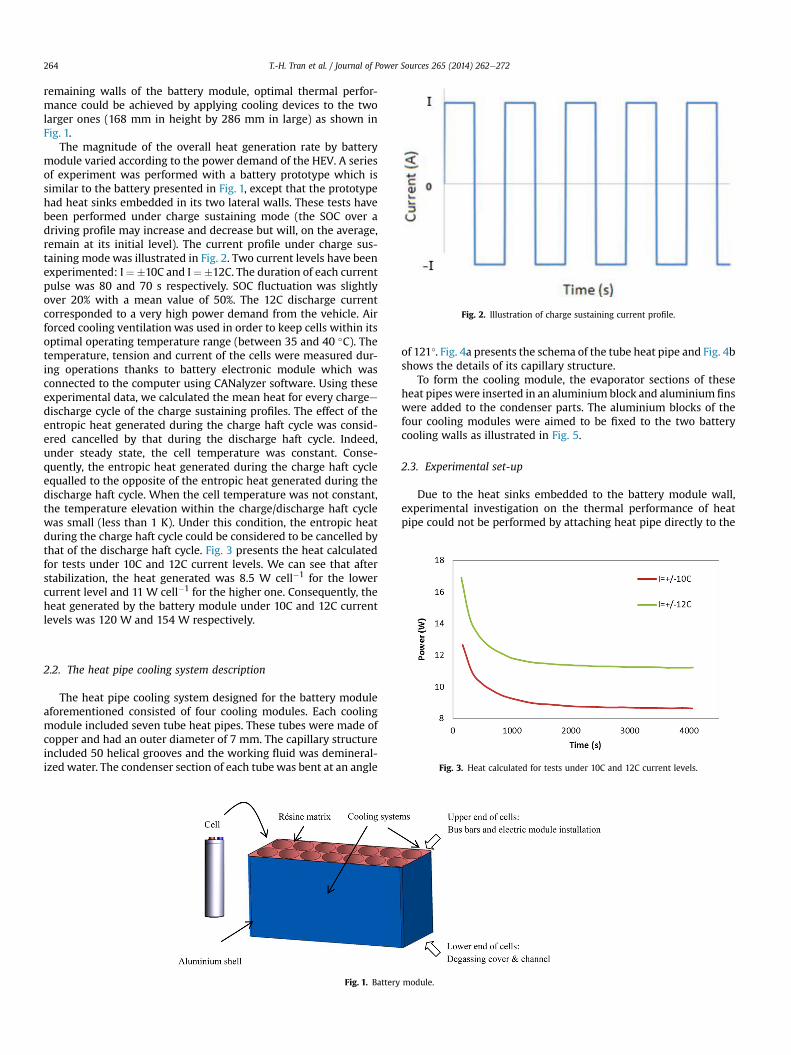
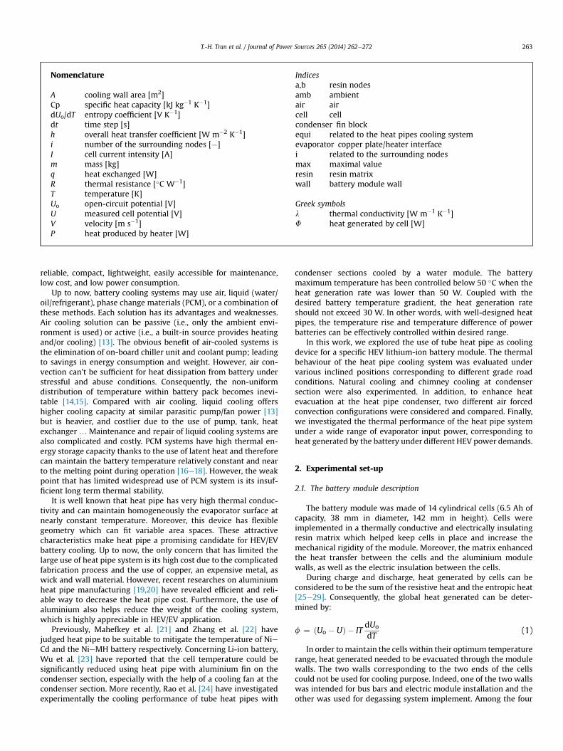
Fig. 2. Illustration of charge sustaining current profile.
T.-H. Tran et al. / Journal of Power Sources 265 (2014) 262e272264
remaining walls of the battery module, optimal thermal perfor-mance could be achieved by applying cooling devices to the twolarger ones (168 mm in height by 286 mm in large) as shown inFig. 1.
The magnitude of the overall heat generation rate by batterymodule varied according to the power demand of the HEV. A seriesof experiment was performed with a battery prototype which issimilar to the battery presented in Fig. 1, except that the prototypehad heat sinks embedded in its two lateral walls. These tests havebeen performed under charge sustaining mode (the SOC over adriving profile may increase and decrease but will, on the average,remain at its initial level). The current profile under charge sus-taining mode was illustrated in Fig. 2. Two current levels have beenexperimented: I¼�10C and I¼�12C. The duration of each currentpulse was 80 and 70 s respectively. SOC fluctuation was slightlyover 20% with a mean value of 50%. The 12C discharge currentcorresponded to a very high power demand from the vehicle. Airforced cooling ventilation was used in order to keep cells within itsoptimal operating temperature range (between 35 and 40 �C). Thetemperature, tension and current of the cells were measured dur-ing operations thanks to battery electronic module which wasconnected to the computer using CANalyzer software. Using theseexperimental data, we calculated the mean heat for every chargeedischarge cycle of the charge sustaining profiles. The effect of theentropic heat generated during the charge haft cycle was consid-ered cancelled by that during the discharge haft cycle. Indeed,under steady state, the cell temperature was constant. Conse-quently, the entropic heat generated during the charge haft cycleequalled to the opposite of the entropic heat generated during thedischarge haft cycle. When the cell temperature was not constant,the temperature elevation within the charge/discharge haft cyclewas small (less than 1 K). Under this condition, the entropic heatduring the charge haft cycle could be considered to be cancelled bythat of the discharge haft cycle. Fig. 3 presents the heat calculatedfor tests under 10C and 12C current levels. We can see that afterstabilization, the heat generated was 8.5 W cell�1 for the lowercurrent level and 11 W cell�1 for the higher one. Consequently, theheat generated by the battery module under 10C and 12C currentlevels was 120 W and 154 W respectively.
Fig. 3. Heat calculated for tests under 10C and 12C current levels.
2.2. The heat pipe cooling system description
The heat pipe cooling system designed for the battery moduleaforementioned consisted of four cooling modules. Each coolingmodule included seven tube heat pipes. These tubes were made ofcopper and had an outer diameter of 7 mm. The capillary structureincluded 50 helical grooves and the working fluid was demineral-ized water. The condenser section of each tubewas bent at an angle
Fig. 1. Battery
of 121�. Fig. 4a presents the schema of the tube heat pipe and Fig. 4bshows the details of its capillary structure.
To form the cooling module, the evaporator sections of theseheat pipes were inserted in an aluminium block and aluminium finswere added to the condenser parts. The aluminium blocks of thefour cooling modules were aimed to be fixed to the two batterycooling walls as illustrated in Fig. 5.
2.3. Experimental set-up
Due to the heat sinks embedded to the battery module wall,experimental investigation on the thermal performance of heatpipe could not be performed by attaching heat pipe directly to the
module.
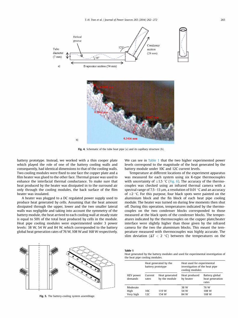
Fig. 4. Schematic of the tube heat pipe (a) and its capillary structure (b).
T.-H. Tran et al. / Journal of Power Sources 265 (2014) 262e272 265
battery prototype. Instead, we worked with a thin cooper platewhich played the role of one of the battery cooling walls andconsequently, had identical dimensions to that of the cooling walls.Two cooling modules were fixed to one face the copper plate and afilm heater was glued to the other face. Thermal grease was used toenhance the interfacial thermal conductance. To make sure thatheat produced by the heater was dissipated in to the surround aironly through the cooling modules, the back surface of the filmheater was insulated.
A heater was plugged to a DC regulated power supply used toproduce heat generated by cells. Assuming that the heat amountdissipated through the upper, lower and the two smaller lateralwalls was negligible and taking into account the symmetry of thebatterymodule, the heat arrived to each cooling wall at steady stateis equal to 50% of the total heat produced by cells in the module.Heat pipe cooling modules were experimented under 3 powerlevels: 38 W, 54 W and 84 W, which corresponded to the batteryglobal heat generation rates of 76W,108Wand 168W respectively.
Fig. 5. The battery-cooling system assemblage.
We can see in Table 1 that the two higher experimented powerlevels correspond to the magnitude of the heat generated by thebattery module under 10C and 12C current levels.
Temperature at different locations of the experiment apparatuswas measured for each system using six K-type thermocoupleswith uncertainty of �1.5 �C (Fig. 6). The accuracy of the thermo-couples was checked using an infrared thermal camera with aspectral range of 7.5e13 mm, a resolution of 0.01 �C and an accuracyof �2 �C. For this purpose, four black spots were painted on thealuminium block and the fin block of each heat pipe coolingmodule. The heater was turned on during few moments then shutoff. During this operation, temperatures indicated by the thermo-couples on the two condenser blocks corresponded to thosemeasured at the black spots of the condenser blocks. The temper-atures indicated by the thermocouples on the copper plate/heaterinterface were slightly higher than those given by the infraredcamera for the two the aluminium blocks. This meant the tem-perature measured with thermocouples was highly accurate. Theslim deviation (DT < 2 �C) between the temperatures on the
Table 1Heat generated by the battery modules and used for experimental investigation ofthe heat pipe cooling modules.
Heat generated by thebattery prototype
Heat used for experimentalinvestigation of the heat pipecooling modules
HEV powerdemands
Currentrates
Heat generatedby the module
Heat producedby heater
Battery globalheat generationrates
Moderate 38 W 76 WHigh 10C 119 W 54 W 108 WVery high 12C 154 W 84 W 168 W
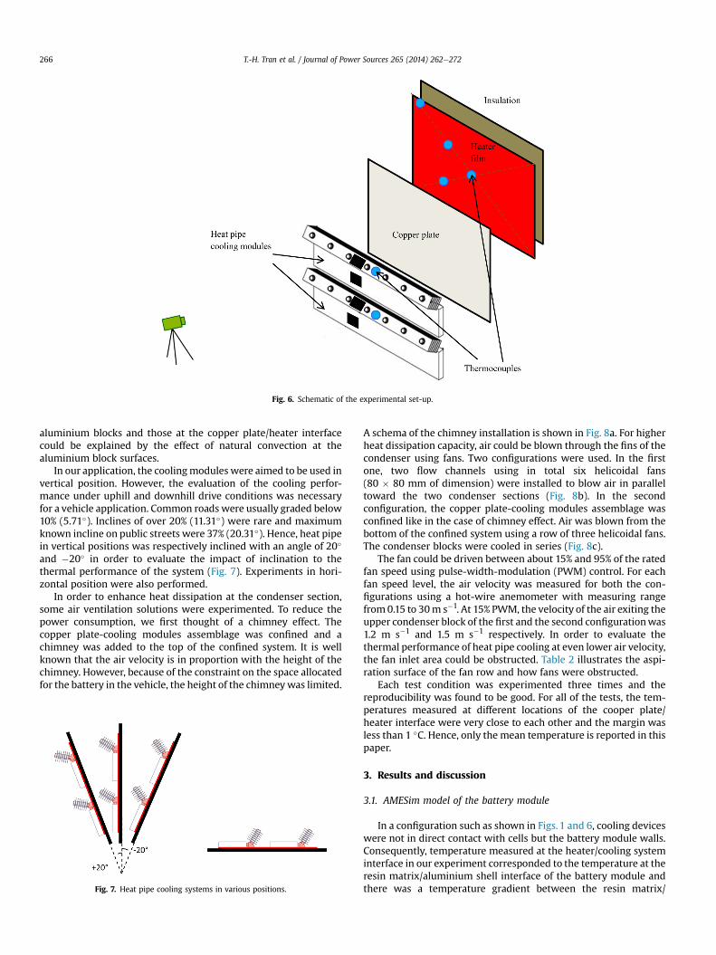
Fig. 6. Schematic of the experimental set-up.
T.-H. Tran et al. / Journal of Power Sources 265 (2014) 262e272266
aluminium blocks and those at the copper plate/heater interfacecould be explained by the effect of natural convection at thealuminium block surfaces.
In our application, the coolingmodules were aimed to be used invertical position. However, the evaluation of the cooling perfor-mance under uphill and downhill drive conditions was necessaryfor a vehicle application. Common roads were usually graded below10% (5.71�). Inclines of over 20% (11.31�) were rare and maximumknown incline on public streets were 37% (20.31�). Hence, heat pipein vertical positions was respectively inclined with an angle of 20�
and �20� in order to evaluate the impact of inclination to thethermal performance of the system (Fig. 7). Experiments in hori-zontal position were also performed.
In order to enhance heat dissipation at the condenser section,some air ventilation solutions were experimented. To reduce thepower consumption, we first thought of a chimney effect. Thecopper plate-cooling modules assemblage was confined and achimney was added to the top of the confined system. It is wellknown that the air velocity is in proportion with the height of thechimney. However, because of the constraint on the space allocatedfor the battery in the vehicle, the height of the chimneywas limited.
Fig. 7. Heat pipe cooling systems in various positions.
A schema of the chimney installation is shown in Fig. 8a. For higherheat dissipation capacity, air could be blown through the fins of thecondenser using fans. Two configurations were used. In the firstone, two flow channels using in total six helicoidal fans(80 � 80 mm of dimension) were installed to blow air in paralleltoward the two condenser sections (Fig. 8b). In the secondconfiguration, the copper plate-cooling modules assemblage wasconfined like in the case of chimney effect. Air was blown from thebottom of the confined system using a row of three helicoidal fans.The condenser blocks were cooled in series (Fig. 8c).
The fan could be driven between about 15% and 95% of the ratedfan speed using pulse-width-modulation (PWM) control. For eachfan speed level, the air velocity was measured for both the con-figurations using a hot-wire anemometer with measuring rangefrom0.15 to 30m s�1. At 15% PWM, the velocity of the air exiting theupper condenser block of the first and the second configurationwas1.2 m s�1 and 1.5 m s�1 respectively. In order to evaluate thethermal performance of heat pipe cooling at even lower air velocity,the fan inlet area could be obstructed. Table 2 illustrates the aspi-ration surface of the fan row and how fans were obstructed.
Each test condition was experimented three times and thereproducibility was found to be good. For all of the tests, the tem-peratures measured at different locations of the cooper plate/heater interface were very close to each other and the margin wasless than 1 �C. Hence, only the mean temperature is reported in thispaper.
3. Results and discussion
3.1. AMESim model of the battery module
In a configuration such as shown in Figs. 1 and 6, cooling deviceswere not in direct contact with cells but the battery module walls.Consequently, temperature measured at the heater/cooling systeminterface in our experiment corresponded to the temperature at theresin matrix/aluminium shell interface of the battery module andthere was a temperature gradient between the resin matrix/
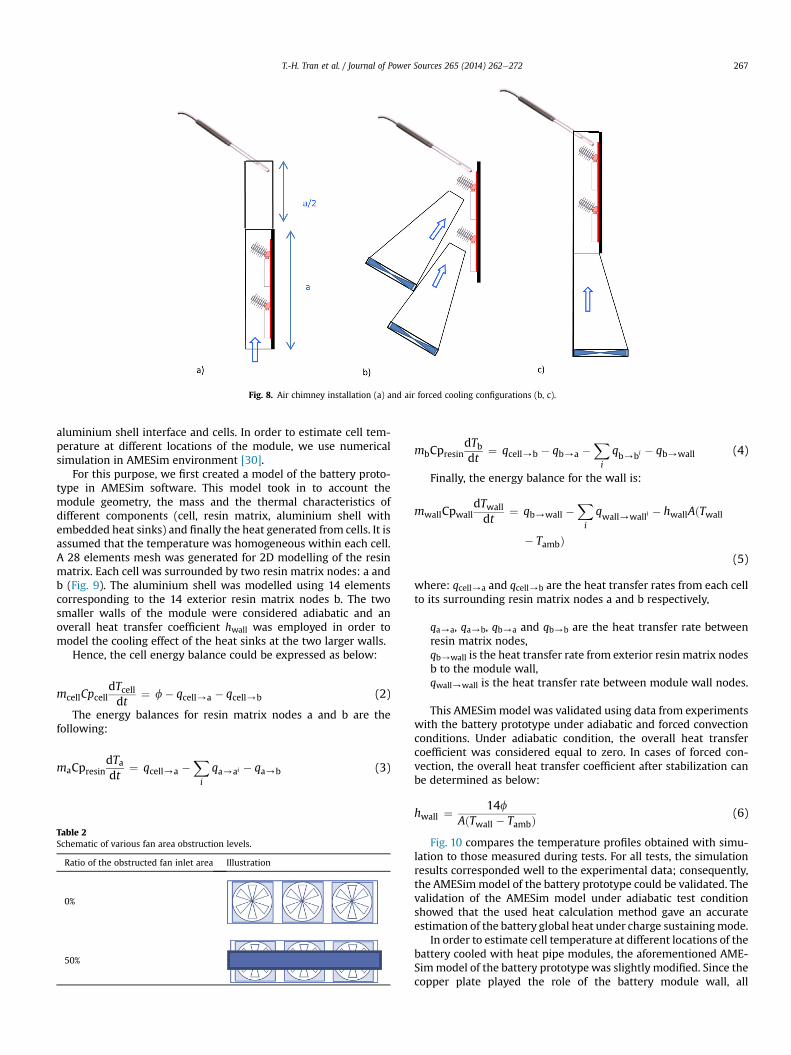
Fig. 8. Air chimney installation (a) and air forced cooling configurations (b, c).
T.-H. Tran et al. / Journal of Power Sources 265 (2014) 262e272 267
aluminium shell interface and cells. In order to estimate cell tem-perature at different locations of the module, we use numericalsimulation in AMESim environment [30].
For this purpose, we first created a model of the battery proto-type in AMESim software. This model took in to account themodule geometry, the mass and the thermal characteristics ofdifferent components (cell, resin matrix, aluminium shell withembedded heat sinks) and finally the heat generated from cells. It isassumed that the temperature was homogeneous within each cell.A 28 elements mesh was generated for 2D modelling of the resinmatrix. Each cell was surrounded by two resin matrix nodes: a andb (Fig. 9). The aluminium shell was modelled using 14 elementscorresponding to the 14 exterior resin matrix nodes b. The twosmaller walls of the module were considered adiabatic and anoverall heat transfer coefficient hwall was employed in order tomodel the cooling effect of the heat sinks at the two larger walls.
Hence, the cell energy balance could be expressed as below:
mcellCpcelldTcelldt
¼ f� qcell/a � qcell/b (2)
The energy balances for resin matrix nodes a and b are thefollowing:
maCpresindTadt
¼ qcell/a �X
i
qa/ai � qa/b (3)
Table 2Schematic of various fan area obstruction levels.
Ratio of the obstructed fan inlet area Illustration
0%
50%
mbCpresindTbdt
¼ qcell/b � qb/a �X
i
qb/bi � qb/wall (4)
Finally, the energy balance for the wall is:
mwallCpwalldTwalldt
¼ qb/wall �X
i
qwall/walli � hwallAðTwall
� TambÞ(5)
where: qcell/a and qcell/b are the heat transfer rates from each cellto its surrounding resin matrix nodes a and b respectively,
qa/a, qa/b, qb/a and qb/b are the heat transfer rate betweenresin matrix nodes,qb/wall is the heat transfer rate from exterior resin matrix nodesb to the module wall,qwall/wall is the heat transfer rate between module wall nodes.
This AMESimmodel was validated using data from experimentswith the battery prototype under adiabatic and forced convectionconditions. Under adiabatic condition, the overall heat transfercoefficient was considered equal to zero. In cases of forced con-vection, the overall heat transfer coefficient after stabilization canbe determined as below:
hwall ¼14f
AðTwall � TambÞ(6)
Fig. 10 compares the temperature profiles obtained with simu-lation to those measured during tests. For all tests, the simulationresults corresponded well to the experimental data; consequently,the AMESimmodel of the battery prototype could be validated. Thevalidation of the AMESim model under adiabatic test conditionshowed that the used heat calculation method gave an accurateestimation of the battery global heat under charge sustainingmode.
In order to estimate cell temperature at different locations of thebattery cooled with heat pipe modules, the aforementioned AME-Simmodel of the battery prototype was slightly modified. Since thecopper plate played the role of the battery module wall, all
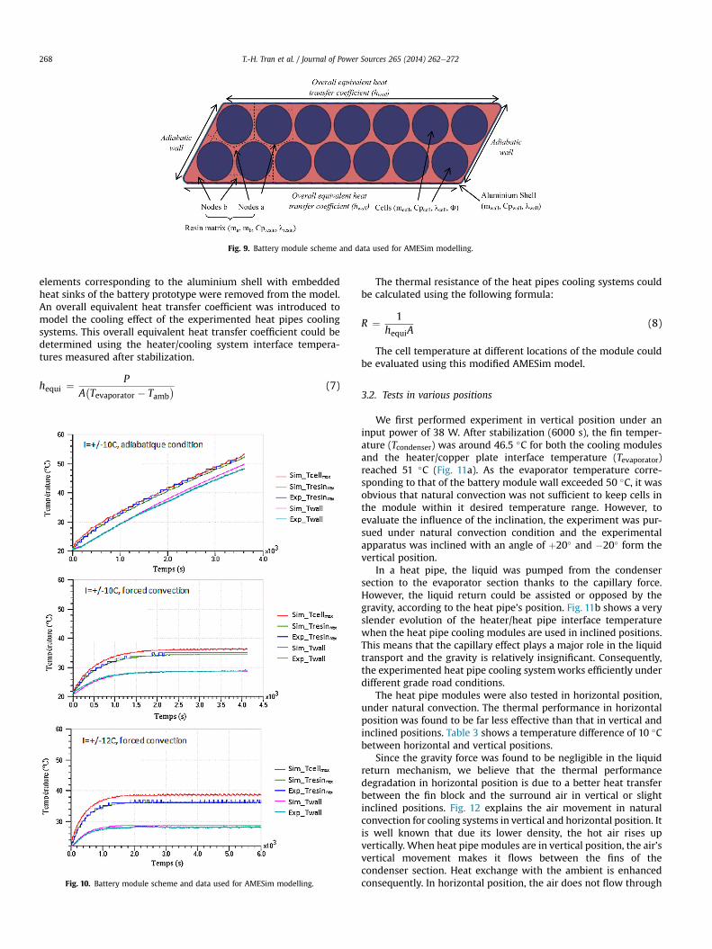
Fig. 9. Battery module scheme and data used for AMESim modelling.
T.-H. Tran et al. / Journal of Power Sources 265 (2014) 262e272268
elements corresponding to the aluminium shell with embeddedheat sinks of the battery prototype were removed from the model.An overall equivalent heat transfer coefficient was introduced tomodel the cooling effect of the experimented heat pipes coolingsystems. This overall equivalent heat transfer coefficient could bedetermined using the heater/cooling system interface tempera-tures measured after stabilization.
hequi ¼P
A�Tevaporator � Tamb
� (7)
Fig. 10. Battery module scheme and data used for AMESim modelling.
The thermal resistance of the heat pipes cooling systems couldbe calculated using the following formula:
R ¼ 1hequiA
(8)
The cell temperature at different locations of the module couldbe evaluated using this modified AMESim model.
3.2. Tests in various positions
We first performed experiment in vertical position under aninput power of 38 W. After stabilization (6000 s), the fin temper-ature (Tcondenser) was around 46.5 �C for both the cooling modulesand the heater/copper plate interface temperature (Tevaporator)reached 51 �C (Fig. 11a). As the evaporator temperature corre-sponding to that of the battery module wall exceeded 50 �C, it wasobvious that natural convection was not sufficient to keep cells inthe module within it desired temperature range. However, toevaluate the influence of the inclination, the experiment was pur-sued under natural convection condition and the experimentalapparatus was inclined with an angle of þ20� and �20� form thevertical position.
In a heat pipe, the liquid was pumped from the condensersection to the evaporator section thanks to the capillary force.However, the liquid return could be assisted or opposed by thegravity, according to the heat pipe’s position. Fig. 11b shows a veryslender evolution of the heater/heat pipe interface temperaturewhen the heat pipe cooling modules are used in inclined positions.This means that the capillary effect plays a major role in the liquidtransport and the gravity is relatively insignificant. Consequently,the experimented heat pipe cooling systemworks efficiently underdifferent grade road conditions.
The heat pipe modules were also tested in horizontal position,under natural convection. The thermal performance in horizontalposition was found to be far less effective than that in vertical andinclined positions. Table 3 shows a temperature difference of 10 �Cbetween horizontal and vertical positions.
Since the gravity force was found to be negligible in the liquidreturn mechanism, we believe that the thermal performancedegradation in horizontal position is due to a better heat transferbetween the fin block and the surround air in vertical or slightinclined positions. Fig. 12 explains the air movement in naturalconvection for cooling systems in vertical and horizontal position. Itis well known that due its lower density, the hot air rises upvertically. When heat pipe modules are in vertical position, the air’svertical movement makes it flows between the fins of thecondenser section. Heat exchange with the ambient is enhancedconsequently. In horizontal position, the air does not flow through
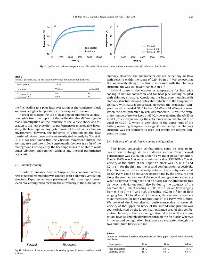
Fig. 11. (a) Vertical position: temperature profile under 38 W input power and natural convection. (b) Influence of inclination.
Table 3Thermal performance of the system in vertical and horizontal positions.
Input power 38 W
Heat pipe Vertical Horizontal
Tevaporator (�C) 51 61Tcondenser (�C) 46.5 56
T.-H. Tran et al. / Journal of Power Sources 265 (2014) 262e272 269
the fins leading to a poor heat evacuation at the condenser blockand thus, a higher temperature at the evaporator section.
In order to validate the use of heat pipe in automotive applica-tion, aside from the impact of the inclination due different graderoads, investigation on the influence of the vehicle shock and vi-bration to the heat pipe thermal performance is unavoidable. In ourstudy, the heat pipe cooling system was not tested under vibrationenvironment; however, the influence of vibration on the heattransfer of microgroove has been investigated recently by Guo et al.[31]. It has been found that the vibration movement enlarge thewetting area and intensified consequently the heat transfer of themicrogroove. Consequently, the heat pipe seems to be able to workunder vibration environment without any thermal performancedegradation.
3.3. Chimney cooling
In order to enhance heat exchange at the condenser section,heat pipe cooling modules was coupled with a chimney ventilationstructure. Experiments were performed under three input powerlevels. We attempted to measure the air velocity at the outlet of the
Fig. 12. Schematic of the air movement for cooling system in vertical and horizontalposition.
chimney. However, the anemometer did not detect any air flowwith velocity within the range of 0.15e30 m s�1. We believe thatthe air velocity though the fins is increased with the chimneystructure but was still lower than 0.15 m s�1.
Table 4 presents the evaporator temperature for heat pipecooling in natural convection and for heat pipe cooling coupledwith chimney structure. Associating the heat pipe modules withchimney structure showed noticeable reduction of the temperaturecompare with natural convection. However, the evaporator tem-perature still exceeded 50 �C for both 54Wand 84W input powers.When the heat generated by cell was moderate (38 W), the evap-orator temperature was keep at 46 �C. However, using the AMESimmodel presented previously, the cells temperature was found to beequal to 49.70 �C, which is very close to the upper limit of thebattery operating temperature range. Consequently, the chimneystructure was not sufficient to keep cell within the desired tem-perature range.
3.4. Influence of the air forced cooling configuration
Two forced convection configurations could be used to in-crease heat exchange at the condenser section. Their thermalperformance was evaluated under 54 W input power condition.The fan PWMwas first set at its minimal value (15% PWM). The airvelocity at the outlet of the upper fin block was 1.5 m s�1 and1.2 m s�1 for the first and the second configuration respectively.The difference of the air velocity between two configurations atiso fan PWM could be explained on one hand by the pressure dropalong the confined section of the second configuration, especiallywhen air flowed through the first fin block. On the other hand, thisair velocity deviation could also be due to the accuracy of theanemometer (�3% of reading þ 0.05 m s�1 for air flow rangingfrom 0.15 to 3 m s�1 and �3% of reading þ0.2 m s�1 for air flowranging from 3.1 to 30 m s�1). However, the evaporator temper-ature measured for both configurations at 15% PWM was similar.We believed the lower thermal performance due to lower airvelocity at the upper fin block of the second configuration wascounterbalanced by the larger heat exchange area of this config-uration. Indeed, in the first configuration, due to air flows orien-tation, heat was mainly dissipated through the fin blocks whereasin the second configuration, heat was also evacuated though thetwo aluminium blocks surface.
Table 4Copper plate/heater interface temperature for heat pipe coupled with chimneyventilation.
Input power 38 W 54 W 84 W
Free convection 51 �C 58 �C 71 �CChimney effect 46 �C 53 �C 66 �C
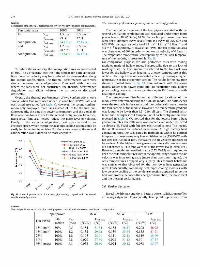
Table 5Comparison of the thermal performance between two air ventilation configurations.
T.-H. Tran et al. / Journal of Power Sources 265 (2014) 262e272270
To reduce the air velocity, the fan aspiration areawas obstructedof 50%. The air velocity was this time similar for both configura-tions. Lower air velocity may have reduced the pressure drop alongthe second configuration. The thermal performances were verysimilar between two configurations. Compared with the casewhere the fans were not obstructed, the thermal performancedegradation was slight whereas the air velocity decreaseddrastically.
Overall, the thermal performances of two configurations weresimilar when fans were used under iso conditions (PWM rate andobstructed area ratio) (see Table 5). However, the second configu-ration only employed three fans instead of six for the first one.Consequently, the parasitic power consumption and the global airflow were two times lower for the second configuration. Moreover,using fewer fans also helped reduce the noise level of vehicles.Finally, in the second configuration, heat pipes worked in anenclosed space, whichmeant the heat pipe cooling system could beeasily implemented in vehicles. For the above reasons, the secondconfiguration was judged to be more adequate.
Fig. 13. Thermal performance of the heat pipe cooling coupled with the secondventilation configuration.
Table 6Thermal performance of heat pipe cooling system coupled with the second ventilation c
3.5. Thermal performance panel of the second configuration
The thermal performance of the heat pipes associated with thesecond ventilation configuration was evaluated under three inputpower levels: 38 W, 54 W, 84 W. For each input power, the fanswere set at different PWM levels from 15% PWM to 25%, 50% and95% PWM, giving an air velocity of 1.2m s�1,1.8m s�1, 2.8 m s�1 and4.3 m s�1 respectively. At lowest fan PWM, the fan aspiration areawas obstructed of 50% in order to get low air velocity of 0.5 m s�1.The evaporator temperature, corresponding to the wall tempera-ture of the module, is presented in Fig. 13.For comparison purpose, we also performed tests with coolingmodules made of hollow tubes. Theoretically, due to the lack ofworking fluid, the heat amount transferred to the fin block waslower for the hollow tube, leading to a lower temperature at thissection. Heat input was not evacuated efficiently causing a highertemperature at the evaporator section. The results for hollow tubeshown in dotted lines in Fig. 13 were coherent with the abovetheory. Under high power input and low ventilation rate, hollowpipes cooling degraded the temperature up to 10 �C compare withheat pipes cooling.
The temperature distribution at different locations of themodulewas determined using the AMESimmodel. The hottest cellswere the two cells in the centre and the coolest cells were those inthe four corners of the module. However, the temperature gradientwas found to be lower than 1.5 �C for all tests. The thermal resis-tance and the highest cell temperature of each configuration werereported in Table 6. We noticed that for the lowest battery heatgeneration rates, the cells were over-cooled even under restrictedair flows (15% PWM with fan area obstructed or not). This meansthe air flow could be reduced even more. At high battery heatgeneration rates, the cells could be maintained within its optimaltemperature range using very low ventilation rates (15% PWMwithfan area obstructed or not). Increasing the air velocity appeared tobe useless. At the highest heat generation rate, cells temperaturesdid not exceed 50 �C if fans were set at the lowest PWM level (15%).However, a moderate ventilation rate (25% PWM) was required tokeep the cells temperatures within the optimal range. When the airvelocity was increased greatly (more than two times higher), thecells temperatures dropped very slightly. This thermal behaviourwas similar to that observed for the two lower heat generationrates. Consequently, combining heat pipes cooling modules withlow velocity cooling at the condenser section appeared to be thebest compromise between the energy consumption, the noise leveland the thermal performance.
3.6. Further discussion
In real life driving conditions, battery power solicitation profilesare always dynamic. Consequently, heat profiles generated from
onfiguration.
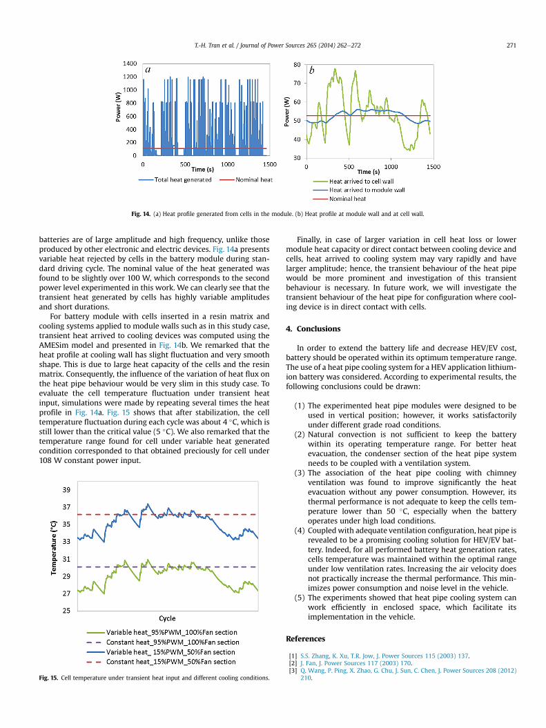
Fig. 14. (a) Heat profile generated from cells in the module. (b) Heat profile at module wall and at cell wall.
T.-H. Tran et al. / Journal of Power Sources 265 (2014) 262e272 271
batteries are of large amplitude and high frequency, unlike thoseproduced by other electronic and electric devices. Fig. 14a presentsvariable heat rejected by cells in the battery module during stan-dard driving cycle. The nominal value of the heat generated wasfound to be slightly over 100 W, which corresponds to the secondpower level experimented in this work. We can clearly see that thetransient heat generated by cells has highly variable amplitudesand short durations.
For battery module with cells inserted in a resin matrix andcooling systems applied to module walls such as in this study case,transient heat arrived to cooling devices was computed using theAMESim model and presented in Fig. 14b. We remarked that theheat profile at cooling wall has slight fluctuation and very smoothshape. This is due to large heat capacity of the cells and the resinmatrix. Consequently, the influence of the variation of heat flux onthe heat pipe behaviour would be very slim in this study case. Toevaluate the cell temperature fluctuation under transient heatinput, simulations were made by repeating several times the heatprofile in Fig. 14a. Fig. 15 shows that after stabilization, the celltemperature fluctuation during each cycle was about 4 �C, which isstill lower than the critical value (5 �C). We also remarked that thetemperature range found for cell under variable heat generatedcondition corresponded to that obtained preciously for cell under108 W constant power input.
Fig. 15. Cell temperature under transient heat input and different cooling conditions.
Finally, in case of larger variation in cell heat loss or lowermodule heat capacity or direct contact between cooling device andcells, heat arrived to cooling system may vary rapidly and havelarger amplitude; hence, the transient behaviour of the heat pipewould be more prominent and investigation of this transientbehaviour is necessary. In future work, we will investigate thetransient behaviour of the heat pipe for configuration where cool-ing device is in direct contact with cells.
4. Conclusions
In order to extend the battery life and decrease HEV/EV cost,battery should be operated within its optimum temperature range.The use of a heat pipe cooling system for a HEV application lithium-ion battery was considered. According to experimental results, thefollowing conclusions could be drawn:
(1) The experimented heat pipe modules were designed to beused in vertical position; however, it works satisfactorilyunder different grade road conditions.
(2) Natural convection is not sufficient to keep the batterywithin its operating temperature range. For better heatevacuation, the condenser section of the heat pipe systemneeds to be coupled with a ventilation system.
(3) The association of the heat pipe cooling with chimneyventilation was found to improve significantly the heatevacuation without any power consumption. However, itsthermal performance is not adequate to keep the cells tem-perature lower than 50 �C, especially when the batteryoperates under high load conditions.
(4) Coupledwith adequate ventilation configuration, heat pipe isrevealed to be a promising cooling solution for HEV/EV bat-tery. Indeed, for all performed battery heat generation rates,cells temperature was maintained within the optimal rangeunder low ventilation rates. Increasing the air velocity doesnot practically increase the thermal performance. This min-imizes power consumption and noise level in the vehicle.
(5) The experiments showed that heat pipe cooling system canwork efficiently in enclosed space, which facilitate itsimplementation in the vehicle.
References
[1] S.S. Zhang, K. Xu, T.R. Jow, J. Power Sources 115 (2003) 137.[2] J. Fan, J. Power Sources 117 (2003) 170.[3] Q. Wang, P. Ping, X. Zhao, G. Chu, J. Sun, C. Chen, J. Power Sources 208 (2012)
210.

T.-H. Tran et al. / Journal of Power Sources 265 (2014) 262e272272
[4] M. Broussely, S. Herreyre, P. Biensan, P. Kasztejna, K. Nechev, R.J. Staniewicz,J. Power Sources 97-98 (2001) 130.
[5] M.S. Wu, P.C.J. Chiang, Electrochim. Acta 52 (2007) 3719.[6] P. Ramadass, B. Haran, R. White, B.N. Popov, J. Power Sources 112 (2002) 614.[7] J. Shim, R. Kostecki, T. Richardson, X. Song, K.A. Striebeln, J. Power Sources 112
(2002) 222.[8] G. Sarre, P. Blanchard, M. Broussely, J. Power Sources 127 (2004) 65.[9] M. Fleckensteina, O. Bohlena, M.A. Roscherb, B. Bäkerc, J. Power Sources 196
(2011) 4769.[10] Y. Troxler, B. Wu, M. Marinescu, V. Yufit, Y. Patel, A.J. Marquis, N.P. Brandon,
G.J. Offer, J. Power Sources (2013).[11] A.A. Pesaran, J. Power Sources 110 (2002) 377.[12] C.W. Park, A.K. Jaura, SAE Tech. Pap. (2003).[13] A.A. Pesaran, Advanced Automotive Battery Conference, 2001.[14] A.A. Pesaran, in: Fourth Vehicle Thermal Management Systems Conference
and Exhibition London, 1999.[15] H. Park, J. Power Sources 239 (2013) 30.[16] R. Kizilel, R. Sabbaha, J.R. Selmana, S. AlHallaj, J. Power Sources 194 (2009)
1105.
[17] R. Sabbah, R. Kizilel, J.R. Selman, S. Al-Hallaj, J. Power Sources 182 (2008) 630.[18] G.H. Kim, J. Gonder, J. Lustbader, A. Pesaran, World Electr. Veh. J. 2 (2008) 46.[19] Y.T. Chen, S.W. Kang, Y.H. Hung, C.H. Huang, K.C. Chien, Appl. Therm. Eng. 51
(2013) 864.[20] M. Ameli, B. Agnewa, P.S. Leung, B. Ng, C.J. Sutcliffe, J. Singh, R. McGlen, Appl.
Therm. Eng. 52 (2013) 498.[21] E.T. Mahefkey, M.M. Kreitman, J. Electrochem. Soc. 118 (1971) 1383.[22] G. Zhang, Z. Wu, Z. Rao, L. Fu, Chem. Ind. Eng. Prog. 28 (2009) 1165 (in
Chinese).[23] M.S. Wu, K.H. Liu, Y.Y. Wang, C.C. Wan, J. Power Sources 109 (2002) 160.[24] Z. Rao, S. Wang, M. Wu, Z. Lin, F. Li, Energy Convers. Manag. 65 (2013) 92.[25] D. Bernardi, E. Pawlikowski, J. Newman, J. Electrochem. Soc. 132 (1985) 5e12.[26] L. Rao, J. Newman, J. Electrochem. Soc. 144 (1997) 2697.[27] Y. Saito, K. Kanari, K. Takano, J. Power Sources 68 (1997) 451.[28] K.E. Thomas, J. Newman, J. Power Sources 844 (2003) 119e121.[29] T.H. Tran, S. Harmand, B. Desmet, F. Pailhoux, J. Electrochem. Soc. 160 (2013)
775e780.[30] http://www.lmsintl.com/LMS-Imagine-Lab-AMESim.[31] C. Guo, X. Hu, W. Cao, D. Xu, D. Tang, Appl. Therm. Eng. 52 (2013) 385.
Related Documents