Contents lists available at ScienceDirect Journal of Manufacturing Processes journal homepage: www.elsevier.com/locate/manpro Experimental investigation of phase change materials fabricated using selective laser sintering additive manufacturing Malek Nofal a , Said Al-Hallaj b , Yayue Pan a, ⁎ a University of Illinois at Chicago, 842 W Taylor Street, Chicago, IL, 60607, United States b AllCell Technologies, 2321 W 41 st Street, Chicago, IL, 60609, United States ARTICLE INFO Keywords: 3D printing Selective laser sintering Phase change material Paraffin-graphite composite Self bonding ABSTRACT The increased demand for phase-change-materials-enabled energy storage systems exposed the limitations of established manufacturing methods in terms of material properties, fabrication speed, material waste, and shape- form flexibility. Phase change materials have unique merits in latent heat thermal energy storage, due to its capability of providing high-energy density storage by solidifying/melting at a constant temperature. In this research, a phase change composite was developed by mixing paraffin wax with a thermal conductive expanded graphite. Using a layer-by-layer laser sintering method, these two materials were combined at a micro-scale, forming a phase change composite that possesses good thermal conductivity, superior latent heat, and good mechanical strength. This work investigated the key parameters for successful production of paraffin wax/ex- panded graphite composite using laser sintering technique. In particular, the paraffin wax is melted and then impregnated into the inter-particle pores of expanded graphite through capillaries. It serves as a binder that bonds the expanded graphite molecules together into a solid form-stable object during the laser sintering pro- cess. To validate the developed sintering process, samples with a various number of layers were fabricated and tested. Results showed good structural integrity and functionality of the printed samples. The thermal con- ductivity was in the range of 0.83–0.92 W m -1 K -1 . The latent heat was in the range of 150–156 kJ kg -1 . Modulus of elasticity was between 808–880 MPa while the tensile strength in the range of 2.2–3.3 MPa. The electrical resistivity ranged between 8 and 28 Ohm m. These experimental results verified that the developed laser sintering process could be used as an effective nontraditional manufacturing technique for fabricating phase change materials for thermal energy storage applications. 1. Introduction 1.1. Background Lithium-ion batteries energy density has doubled in the last decade. This allows for more compact and efficient battery-powered goods such as electric vehicles, drones, portable electronics, and renewable energy storage. However, the high-energy density comes with a price of properly maintaining a safe operation of such batteries. The heat gen- erated during charging and discharging might lead to life cycle de- gradation and severe thermal runaway. Therefore, integrating lithium- ion batteries with a mean of cooling mechanism has been a common practice in high power applications. Passive cooling mechanisms which can be achieved by using phase change materials (PCM) has gotten a lot of attention lately. Phase change materials have become game changers in modern thermal energy application. Due to the phenomenon of state change in phase, i.e. solid-liquid or liquid-gas phase change, thermal energy can be stored and extracted in the form of latent heat. The liquid-gas phase change provides a huge amount of latent heat [1]. However, the major drawback of such phase change scheme is the massive volume required to contain the gaseous phase. Therefore, the solid-liquid phase change has been considered a better approach and investigated in many lit- eratures. The key benefit of solid-liquid phase change materials is the high latent heat to sensible heat ratio, where the thermal energy can be stored without significantly increasing the phase change material temperature beyond its melting point. This advantage allows a uniform thermal heat absorption or extraction throughout the system. For thermal energy storage applications that need to store the thermal energy at a fast rate, the thermal conductivity is a major property that needs to be taken into account. Other properties including https://doi.org/10.1016/j.jmapro.2019.05.043 Received 6 April 2018; Received in revised form 7 May 2019; Accepted 31 May 2019 ⁎ Corresponding author. E-mail addresses: [email protected] (M. Nofal), [email protected] (S. Al-Hallaj), [email protected] (Y. Pan). Journal of Manufacturing Processes 44 (2019) 91–101 Available online 06 June 2019 1526-6125/ © 2019 The Society of Manufacturing Engineers. Published by Elsevier Ltd. All rights reserved. T

Welcome message from author
This document is posted to help you gain knowledge. Please leave a comment to let me know what you think about it! Share it to your friends and learn new things together.
Transcript
Contents lists available at ScienceDirect
Journal of Manufacturing Processes
journal homepage: www.elsevier.com/locate/manpro
Experimental investigation of phase change materials fabricated usingselective laser sintering additive manufacturing
Malek Nofala, Said Al-Hallajb, Yayue Pana,⁎
aUniversity of Illinois at Chicago, 842 W Taylor Street, Chicago, IL, 60607, United StatesbAllCell Technologies, 2321 W 41st Street, Chicago, IL, 60609, United States
A R T I C L E I N F O
Keywords:3D printingSelective laser sinteringPhase change materialParaffin-graphite compositeSelf bonding
A B S T R A C T
The increased demand for phase-change-materials-enabled energy storage systems exposed the limitations ofestablished manufacturing methods in terms of material properties, fabrication speed, material waste, and shape-form flexibility. Phase change materials have unique merits in latent heat thermal energy storage, due to itscapability of providing high-energy density storage by solidifying/melting at a constant temperature. In thisresearch, a phase change composite was developed by mixing paraffin wax with a thermal conductive expandedgraphite. Using a layer-by-layer laser sintering method, these two materials were combined at a micro-scale,forming a phase change composite that possesses good thermal conductivity, superior latent heat, and goodmechanical strength. This work investigated the key parameters for successful production of paraffin wax/ex-panded graphite composite using laser sintering technique. In particular, the paraffin wax is melted and thenimpregnated into the inter-particle pores of expanded graphite through capillaries. It serves as a binder thatbonds the expanded graphite molecules together into a solid form-stable object during the laser sintering pro-cess. To validate the developed sintering process, samples with a various number of layers were fabricated andtested. Results showed good structural integrity and functionality of the printed samples. The thermal con-ductivity was in the range of 0.83–0.92Wm−1 K−1. The latent heat was in the range of 150–156 kJ kg−1.Modulus of elasticity was between 808–880MPa while the tensile strength in the range of 2.2–3.3MPa. Theelectrical resistivity ranged between 8 and 28 Ohmm. These experimental results verified that the developedlaser sintering process could be used as an effective nontraditional manufacturing technique for fabricatingphase change materials for thermal energy storage applications.
1. Introduction
1.1. Background
Lithium-ion batteries energy density has doubled in the last decade.This allows for more compact and efficient battery-powered goods suchas electric vehicles, drones, portable electronics, and renewable energystorage. However, the high-energy density comes with a price ofproperly maintaining a safe operation of such batteries. The heat gen-erated during charging and discharging might lead to life cycle de-gradation and severe thermal runaway. Therefore, integrating lithium-ion batteries with a mean of cooling mechanism has been a commonpractice in high power applications. Passive cooling mechanisms whichcan be achieved by using phase change materials (PCM) has gotten a lotof attention lately.
Phase change materials have become game changers in modern
thermal energy application. Due to the phenomenon of state change inphase, i.e. solid-liquid or liquid-gas phase change, thermal energy canbe stored and extracted in the form of latent heat. The liquid-gas phasechange provides a huge amount of latent heat [1]. However, the majordrawback of such phase change scheme is the massive volume requiredto contain the gaseous phase. Therefore, the solid-liquid phase changehas been considered a better approach and investigated in many lit-eratures.
The key benefit of solid-liquid phase change materials is the highlatent heat to sensible heat ratio, where the thermal energy can bestored without significantly increasing the phase change materialtemperature beyond its melting point. This advantage allows a uniformthermal heat absorption or extraction throughout the system.
For thermal energy storage applications that need to store thethermal energy at a fast rate, the thermal conductivity is a majorproperty that needs to be taken into account. Other properties including
https://doi.org/10.1016/j.jmapro.2019.05.043Received 6 April 2018; Received in revised form 7 May 2019; Accepted 31 May 2019
⁎ Corresponding author.E-mail addresses: [email protected] (M. Nofal), [email protected] (S. Al-Hallaj), [email protected] (Y. Pan).
Journal of Manufacturing Processes 44 (2019) 91–101
Available online 06 June 20191526-6125/ © 2019 The Society of Manufacturing Engineers. Published by Elsevier Ltd. All rights reserved.
T
mechanical strength and form stability, which is the ability to containthe liquid phase of the phase change material within the structurewithout leakage, must also be considered. Nevertheless, most phasechange materials have poor thermal conductivities comparing to me-tallic materials such as copper or aluminum. Paraffin wax, for instance,has a thermal conductivity around 0.20Wm−1 K−1 comparing to385Wm−1 K−1 and 205Wm−1 K−1 for copper and aluminum re-spectively [2]. Therefore, many researchers have investigated methodsof combining phase change materials with various thermally con-ductive materials. Sari et al. [3,4] have studied a different combinationof paraffin wax - as a phase change material, with expanded graphiteand high-density polyethylene (HDPE) aiming to enhance the thermalconductivity of the composites. Fang et al. [5] considered a paraffinboron nitride nanomaterial composites due to its superior thermalconductivity, which is ranging between 1700–2000Wm−1 K−1 [6].
In this paper, paraffin wax was selected as a phase change materialdue to its superior stability during phase change, relatively high latentheat capacity, a wide range of melting temperatures, and its low costand commercial availability. Expanded graphite was selected as theform stable matrix due to its superior properties such as lightweight,relatively high thermal conductivity and its commercial availability[7–9].
1.2. Challenges and contribution
Natural graphite structure is based on parallel sheets of carbon thatare held by strong covalent bonds within a two-dimensional layer,forming a hexagonal pattern, while the stacked sheets are held togetherby weak van der Waals bonds [10]. This complex structure makes itdifficult or nearly impossible to break the covalent bonds at a single-layer level. However, in reaction with acids such as sulfuric and nitric,and some heat treatments, the weak van der Waals bonds can break bysome materials, such as the paraffin wax. The capability of breaking the
van der Waals bonds allows the paraffin wax to be impregnated into theexpanded graphite molecule.
To fabricate form-stable composite, many researchers have sug-gested compacting expanded graphite and immersing it in a bath ofmolten paraffin wax for a certain amount of time ranging from a fewminutes to up to 12 h [1,4,7,11]. The immersion time depends on thepart geometry and desired properties. After the bath immersion, thepart is then machined to form the final geometry. Such process is time-consuming and difficult to fabricate composite with accurate wax fillingratio and filling pattern, and in some instances, making a materialwaste up to 90% in volume in the immersion step and the machiningstep.
Additive manufacturing, also known as 3D Printing, is a class of newtechnologies that fabricate a three-dimensional object by accumulatingmaterials, usually from bottom to the top, in a layer-by-layer fashion.Additive manufacturing offers multiple advantages over traditionalmanufacturing techniques, including almost near zero material waste,reduced time to market, and construction of structures not possible withtraditional manufacturing processes. Therefore, this paper investigatesan additive manufacturing technique, Selective Laser Sintering (SLS),for fabricating paraffin wax/expanded graphite composite, to achievethe desired functionalities while free of geometry constraints and ma-terial waste. Despite the efforts in laser sintering of graphite-basedcomposites, successful selective laser sintering of paraffin wax/ex-panded graphite composite has not been reported yet. Expanded gra-phite and paraffin wax have very different thermal behaviors and massdensities. Selective laser sintering of such two very dissimilar materialsto make a functional and form-stable composite is very challenging.
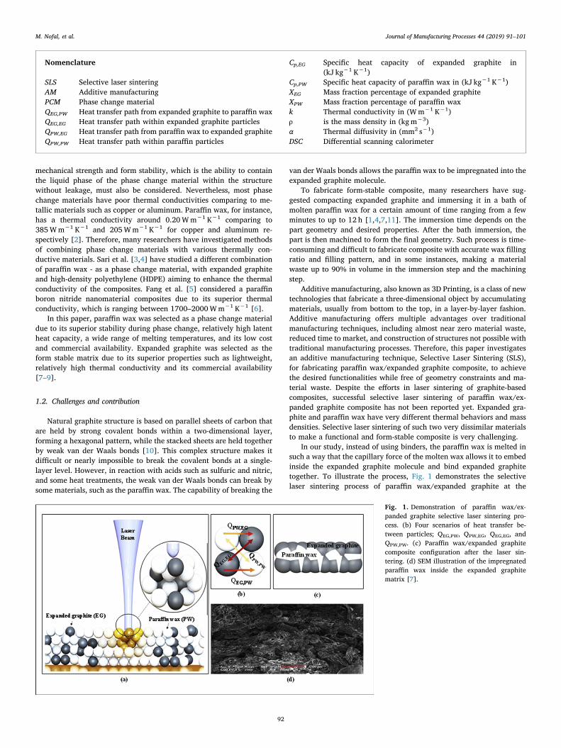
In our study, instead of using binders, the paraffin wax is melted insuch a way that the capillary force of the molten wax allows it to embedinside the expanded graphite molecule and bind expanded graphitetogether. To illustrate the process, Fig. 1 demonstrates the selectivelaser sintering process of paraffin wax/expanded graphite at the
Nomenclature
SLS Selective laser sinteringAM Additive manufacturingPCM Phase change materialQEG,PW Heat transfer path from expanded graphite to paraffin waxQEG,EG Heat transfer path within expanded graphite particlesQPW,EG Heat transfer path from paraffin wax to expanded graphiteQPW,PW Heat transfer path within paraffin particles
Cp,EG Specific heat capacity of expanded graphite in(kJ kg−1 K−1)
Cp,PW Specific heat capacity of paraffin wax in (kJ kg−1 K−1)XEG Mass fraction percentage of expanded graphiteXPW Mass fraction percentage of paraffin waxk Thermal conductivity in (Wm−1 K−1)ρ is the mass density in (kgm−3)α Thermal diffusivity in (mm2 s−1)DSC Differential scanning calorimeter
Fig. 1. Demonstration of paraffin wax/ex-panded graphite selective laser sintering pro-cess. (b) Four scenarios of heat transfer be-tween particles; QEG,PW, QPW,EG, QEG,EG, andQPW,PW. (c) Paraffin wax/expanded graphitecomposite configuration after the laser sin-tering. (d) SEM illustration of the impregnatedparaffin wax inside the expanded graphitematrix [7].
M. Nofal, et al. Journal of Manufacturing Processes 44 (2019) 91–101
92
particle level. White spheres represent the paraffin wax, while the blackspheres represent the expanded graphite. The molten paraffin waximpregnates into the micro-pores of expanded graphite moleculeswithin the melting pool under the capillary force and bonds graphiteparticles together after it solidifies. In Fig. 1, during the sintering pro-cess, QEG,PW is the heat transfer due to conduction from the expandedgraphite to the paraffin wax while QPW,EG is vice versa. QEG,EG is theheat transfer within the expanded graphite particles while QPW,PW is forparaffin wax. It is important to point out that expanded graphite andparaffin wax have significantly different thermal conductivities by threeorders of magnitude. This affects the heat transfer rate between parti-cles, making the selective laser sintering process challenging. Therefore,precise control over the particle size, composition, scan speed, outputlaser power, etc., is required to ensure adequate bonding and pre-dictable heat transfer scheme between the particles. Accordingly, in thispaper, experimental studies and sample characterizations were per-formed to address those challenges and develop the manufacturingprocess for successfully fabricating functional paraffin wax/expandedgraphite composites, with desired properties.
The experiential setup is presented in Section 2.1, followed bymaterials preparations in Section 2.2, and the manufacturing process inSection 2.3. In Sections 3.2 and 3.3, thermal properties of the lasersintered samples are discussed, including the thermal conductivity andlatent heat, which are critical properties in thermal energy storageapplications. To test the form stability of the fabricated composites,mechanical properties such as the ultimate tensile strength and mod-ulus of elasticity were characterized in Section 3.4. Additionally, toassess the functionality of the printed composite in electronics packingapplications, the electrical resistivity of the sintered composite wascharacterized in Section 3.5. Discussion of the functionality of the se-lective laser sintered paraffin wax/graphite composite is given in Sec-tion 3.6, by comparing with the properties of existing phase changecomposite materials used in thermal storage applications. Finally,conclusion and future work are presented in Section 4.
2. Experimental study
2.1. Experimental setup
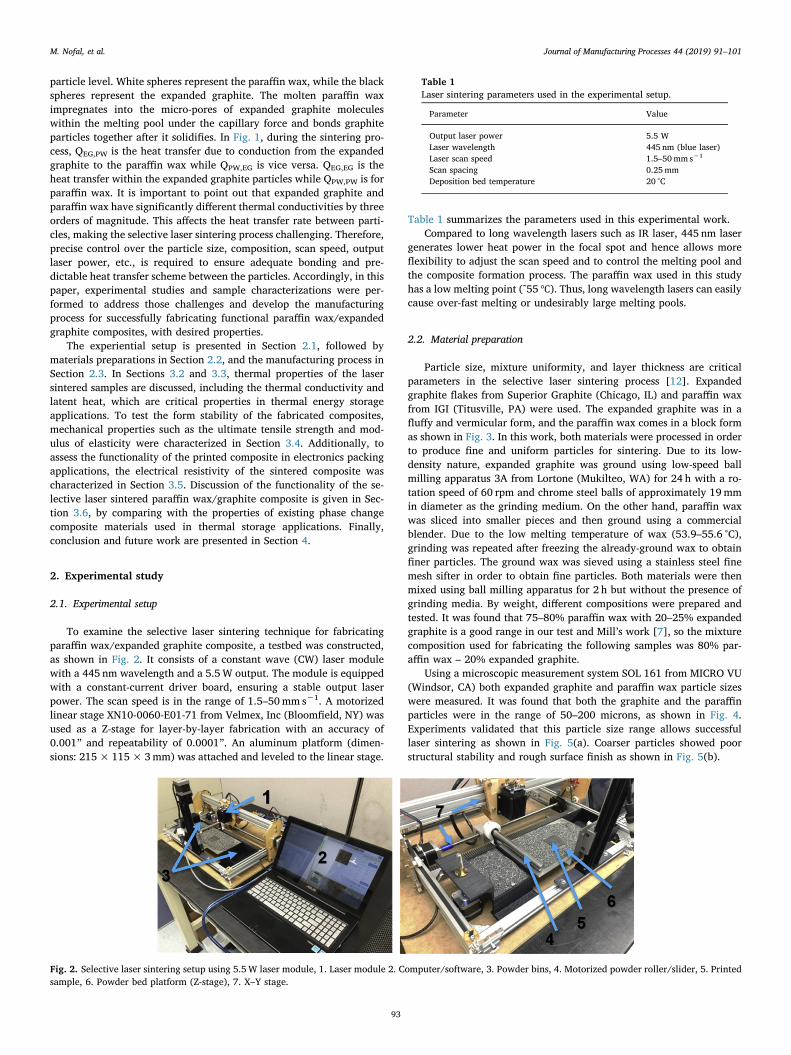
To examine the selective laser sintering technique for fabricatingparaffin wax/expanded graphite composite, a testbed was constructed,as shown in Fig. 2. It consists of a constant wave (CW) laser modulewith a 445 nm wavelength and a 5.5W output. The module is equippedwith a constant-current driver board, ensuring a stable output laserpower. The scan speed is in the range of 1.5–50mm s−1. A motorizedlinear stage XN10-0060-E01-71 from Velmex, Inc (Bloomfield, NY) wasused as a Z-stage for layer-by-layer fabrication with an accuracy of0.001” and repeatability of 0.0001”. An aluminum platform (dimen-sions: 215× 115×3mm) was attached and leveled to the linear stage.
Table 1 summarizes the parameters used in this experimental work.Compared to long wavelength lasers such as IR laser, 445 nm laser
generates lower heat power in the focal spot and hence allows moreflexibility to adjust the scan speed and to control the melting pool andthe composite formation process. The paraffin wax used in this studyhas a low melting point (˜55℃). Thus, long wavelength lasers can easilycause over-fast melting or undesirably large melting pools.
2.2. Material preparation
Particle size, mixture uniformity, and layer thickness are criticalparameters in the selective laser sintering process [12]. Expandedgraphite flakes from Superior Graphite (Chicago, IL) and paraffin waxfrom IGI (Titusville, PA) were used. The expanded graphite was in afluffy and vermicular form, and the paraffin wax comes in a block formas shown in Fig. 3. In this work, both materials were processed in orderto produce fine and uniform particles for sintering. Due to its low-density nature, expanded graphite was ground using low-speed ballmilling apparatus 3A from Lortone (Mukilteo, WA) for 24 h with a ro-tation speed of 60 rpm and chrome steel balls of approximately 19mmin diameter as the grinding medium. On the other hand, paraffin waxwas sliced into smaller pieces and then ground using a commercialblender. Due to the low melting temperature of wax (53.9–55.6 °C),grinding was repeated after freezing the already-ground wax to obtainfiner particles. The ground wax was sieved using a stainless steel finemesh sifter in order to obtain fine particles. Both materials were thenmixed using ball milling apparatus for 2 h but without the presence ofgrinding media. By weight, different compositions were prepared andtested. It was found that 75–80% paraffin wax with 20–25% expandedgraphite is a good range in our test and Mill’s work [7], so the mixturecomposition used for fabricating the following samples was 80% par-affin wax – 20% expanded graphite.
Using a microscopic measurement system SOL 161 from MICRO VU(Windsor, CA) both expanded graphite and paraffin wax particle sizeswere measured. It was found that both the graphite and the paraffinparticles were in the range of 50–200 microns, as shown in Fig. 4.Experiments validated that this particle size range allows successfullaser sintering as shown in Fig. 5(a). Coarser particles showed poorstructural stability and rough surface finish as shown in Fig. 5(b).
Fig. 2. Selective laser sintering setup using 5.5W laser module, 1. Laser module 2. Computer/software, 3. Powder bins, 4. Motorized powder roller/slider, 5. Printedsample, 6. Powder bed platform (Z-stage), 7. X–Y stage.
Table 1Laser sintering parameters used in the experimental setup.
Parameter Value
Output laser power 5.5 WLaser wavelength 445 nm (blue laser)Laser scan speed 1.5–50mm s−1
Scan spacing 0.25mmDeposition bed temperature 20 °C
M. Nofal, et al. Journal of Manufacturing Processes 44 (2019) 91–101
93
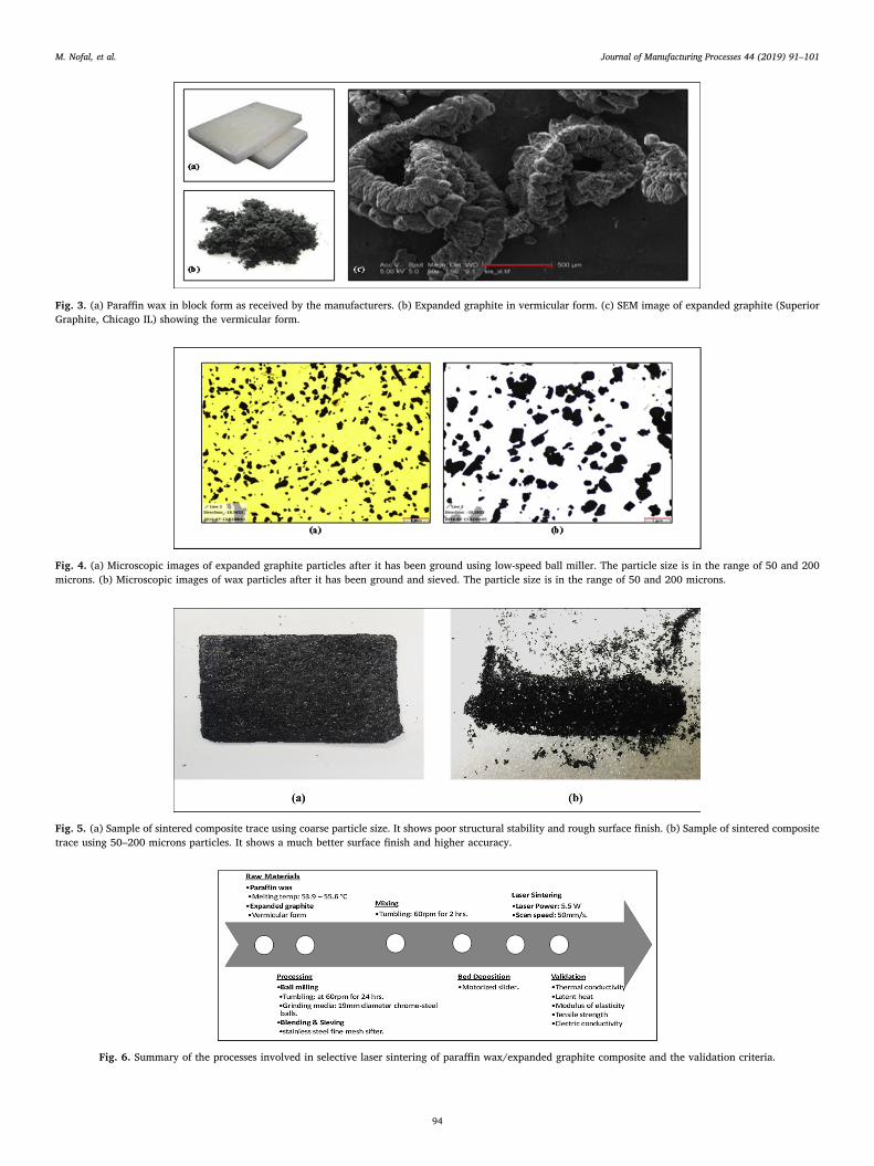
Fig. 3. (a) Paraffin wax in block form as received by the manufacturers. (b) Expanded graphite in vermicular form. (c) SEM image of expanded graphite (SuperiorGraphite, Chicago IL) showing the vermicular form.
Fig. 4. (a) Microscopic images of expanded graphite particles after it has been ground using low-speed ball miller. The particle size is in the range of 50 and 200microns. (b) Microscopic images of wax particles after it has been ground and sieved. The particle size is in the range of 50 and 200 microns.
Fig. 5. (a) Sample of sintered composite trace using coarse particle size. It shows poor structural stability and rough surface finish. (b) Sample of sintered compositetrace using 50–200 microns particles. It shows a much better surface finish and higher accuracy.
Fig. 6. Summary of the processes involved in selective laser sintering of paraffin wax/expanded graphite composite and the validation criteria.
M. Nofal, et al. Journal of Manufacturing Processes 44 (2019) 91–101
94
2.3. Manufacturing process
Fig. 6 describes the process of additive manufacturing of graphite-paraffin composites using selective laser sintering technique. The pro-cess starts from off-the-shelf paraffin wax and expanded graphite. Auniform mixture of graphite and paraffin particles is prepared following
the procedure described in Section 2.2 for use as feedstock in the se-lective laser sintering process. To fabricate a 3D graphite-paraffincomposite part, a flat and uniform layer of mixed expanded graphiteand paraffin particles was first deposited for each layer fabrication. Thecomputer-controlled laser module scans the surface of the powdermixture selectively to form the composite using a back-and-forth scan
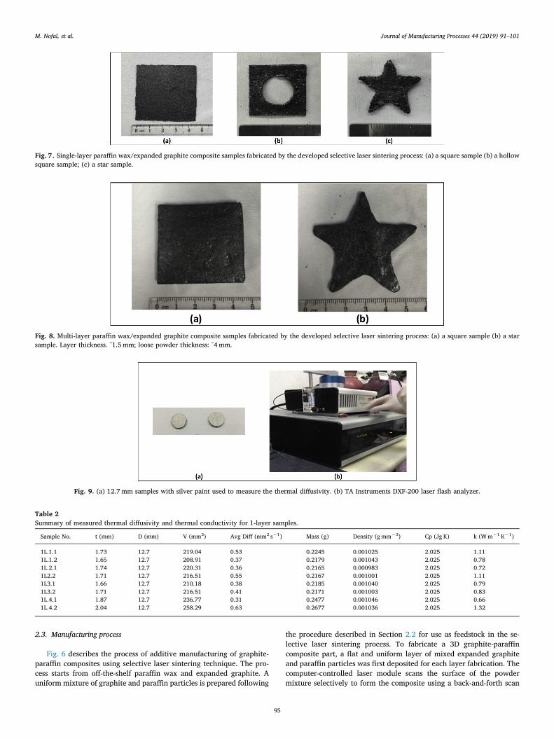
Fig. 7. Single-layer paraffin wax/expanded graphite composite samples fabricated by the developed selective laser sintering process: (a) a square sample (b) a hollowsquare sample; (c) a star sample.
Fig. 8. Multi-layer paraffin wax/expanded graphite composite samples fabricated by the developed selective laser sintering process: (a) a square sample (b) a starsample. Layer thickness. ˜1.5 mm; loose powder thickness: ˜4mm.
Fig. 9. (a) 12.7 mm samples with silver paint used to measure the thermal diffusivity. (b) TA Instruments DXF-200 laser flash analyzer.
Table 2Summary of measured thermal diffusivity and thermal conductivity for 1-layer samples.
Sample No. t (mm) D (mm) V (mm3) Avg Diff (mm2 s−1) Mass (g) Density (gmm−3) Cp (Jg K) k (Wm−1 K−1)
1L.1.1 1.73 12.7 219.04 0.53 0.2245 0.001025 2.025 1.111L.1.2 1.65 12.7 208.91 0.37 0.2179 0.001043 2.025 0.781L.2.1 1.74 12.7 220.31 0.36 0.2165 0.000983 2.025 0.721L2.2 1.71 12.7 216.51 0.55 0.2167 0.001001 2.025 1.111L3.1 1.66 12.7 210.18 0.38 0.2185 0.001040 2.025 0.791L3.2 1.71 12.7 216.51 0.41 0.2171 0.001003 2.025 0.831L.4.1 1.87 12.7 236.77 0.31 0.2477 0.001046 2.025 0.661L.4.2 2.04 12.7 258.29 0.63 0.2677 0.001036 2.025 1.32
M. Nofal, et al. Journal of Manufacturing Processes 44 (2019) 91–101
95
pattern, and a 0.25mm scan spacing. The scan speed could be adjustedin the range of 1.5–50mm s−1 to tune the laser intensity for sinteringparaffin with different melting degrees and hence different impregna-tion capabilities. With our setup and materials, the optimal scan speedwas identified as 50mm s−1, and it was used for the fabrication of thefollowing samples discussed in Section 4. It is important to note that alower scan speed increases the laser beam exposure, leading to an un-controllable melting of paraffin wax and hence low accuracy. On thecontrary, a higher scan speed does not provide enough laser exposure tomelt all the paraffin wax particles and hence low mechanical strengthand inconsistent material properties.
3. Results and discussion
3.1. Samples fabrication
With the developed testbed and prepared materials, we first fabri-cated and characterized single-layer samples to understand the in-layerproperties of the resulted paraffin wax/expanded graphite composite asshown in Fig. 7. To validate the feasibility of fabricating a 3D multi-layer complicated structure and understand the between-layers prop-erties, multi-layer samples with various geometries were also preparedand characterized as shown in Fig. 8. To investigate the functionalitiesof the produced phase change composite in thermal energy storage
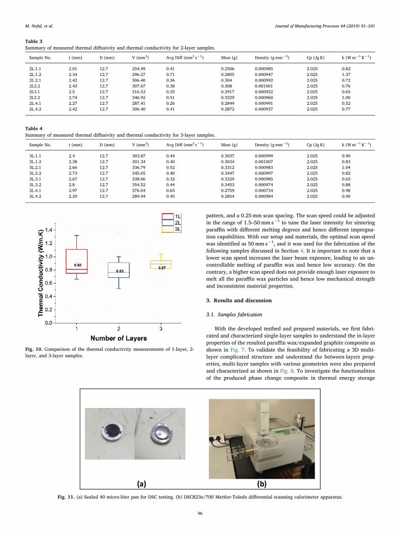
Table 3Summary of measured thermal diffusivity and thermal conductivity for 2-layer samples.
Sample No. t (mm) D (mm) V (mm3) Avg Diff (mm2 s−1) Mass (g) Density (gmm−3) Cp (Jg K) k (Wm−1 K−1)
2L.1.1 2.01 12.7 254.49 0.41 0.2506 0.000985 2.025 0.822L.1.2 2.34 12.7 296.27 0.71 0.2805 0.000947 2.025 1.372L.2.1 2.42 12.7 306.40 0.36 0.304 0.000992 2.025 0.722L2.2 2.43 12.7 307.67 0.38 0.308 0.001001 2.025 0.762L3.1 2.5 12.7 316.53 0.35 0.2917 0.000922 2.025 0.652L3.2 2.74 12.7 346.92 0.51 0.3329 0.000960 2.025 1.002L.4.1 2.27 12.7 287.41 0.26 0.2849 0.000991 2.025 0.522L.4.2 2.42 12.7 306.40 0.41 0.2872 0.000937 2.025 0.77
Table 4Summary of measured thermal diffusivity and thermal conductivity for 3-layer samples.
Sample No. t (mm) D (mm) V (mm3) Avg Diff (mm2 s−1) Mass (g) Density (gmm−3) Cp (Jg K) k (Wm−1 K−1)
3L.1.1 2.4 12.7 303.87 0.44 0.3037 0.000999 2.025 0.903L.1.2 2.38 12.7 301.34 0.40 0.3034 0.001007 2.025 0.833L.2.1 2.66 12.7 336.79 0.52 0.3312 0.000983 2.025 1.043L.2.2 2.73 12.7 345.65 0.40 0.3447 0.000997 2.025 0.823L.3.1 2.67 12.7 338.06 0.32 0.3329 0.000985 2.025 0.653L.3.2 2.8 12.7 354.52 0.44 0.3453 0.000974 2.025 0.883L.4.1 2.97 12.7 376.04 0.65 0.2759 0.000734 2.025 0.983L.4.2 2.29 12.7 289.94 0.45 0.2854 0.000984 2.025 0.90
Fig. 10. Comparison of the thermal conductivity measurements of 1-layer, 2-layer, and 3-layer samples.
Fig. 11. (a) Sealed 40 micro-liter pan for DSC testing. (b) DSC823e/700 Mettler-Toledo differential scanning calorimeter apparatus.
M. Nofal, et al. Journal of Manufacturing Processes 44 (2019) 91–101
96
applications, thermal conductivity, latent heat, mechanical properties,and electrical properties of 1-layer, 2-layer, 3-layer, and 4-layer sam-ples were measured and analyzed in the following sequence.
3.2. Thermal conductivity measurements
Thermal diffusivity was measured using a laser flash analyzer DXF-200 from TA Instruments (New Castle, DE). For 1-layer, 2-layer, and 3-layer samples, two specimens were punched from the original printedsamples (S1, S2, S3, S4) with a constant diameter of 12.7 mm andvarious thicknesses in the range of 2–3mm as shown in Fig.9. The 4-layer samples were too thick to test due to the limitation of the laser
flash analyzer, so they were excluded from thermal conductivity mea-surements.
To enhance the contact with the temperature sensing elements, oneside was brushed with silver paint. Density was calculated, and thespecific heat was estimated using the mass fraction ratio of each ma-terial as seen in Eq. (1):
= +C C X C X[ ] [ ]p p EG EG p PW PW, , (1)
where Cp,EG and Cp,PW are the specific heat of expanded graphite andparaffin wax respectively in (kJ kg−1 K−1), while XEG and XPW denotethe mass fraction percentage of expanded graphite and paraffin wax,respectively. The thermal conductivity, k, can be then calculated usingEq. (2):
=k ρ C αp (2)
where ρ is the mass density in (kgm−3), α is the thermal diffusivity in(mm2 s−1). Tables 2–4 show the measured thermal conductivity resultsfor 1-layer, 2-layer, and 3-layer samples respectively.
From Table 2, it can be seen that the thermal conductivity for 1-layer samples is in the range of 0.66–1.32Wm−1 K−1 with an averageof 0.92Wm−1 K−1. In Table 3, the thermal conductivity for 2 layersamples is in the range of 0.52–1.36Wm−1 K−1 with an average of0.83Wm−1 K−1. In Table 4, the thermal conductivity for 3-layersamples is in the range of 0.65–1.04Wm−1 K−1 with an average of0.87Wm−1 K−1.
Even though the average of each case is very close to each other, theranges differ noticeably. When the number of layers increases, thevariation becomes less. This is due to the anisotropic nature of graphiteparticles when forming a layer structure during sintering.
Overall, sample-to-sample differences in density and thermal con-ductivity were observed as shown in Tables 2–4 and Fig. 10. It may bebecause of the variations in materials composition (paraffin wax toexpanded graphite ratio), the silver painting application, and the errorsin the DXF analyzer measurement.
The thermal conductivity of the 3D printed composite is lower than
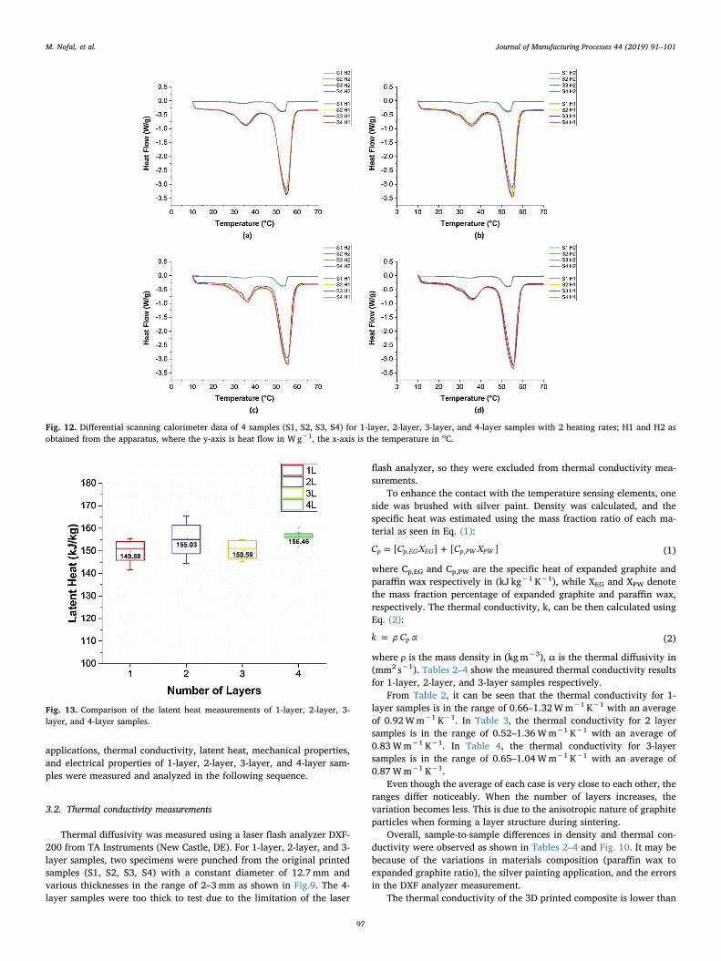
Fig. 12. Differential scanning calorimeter data of 4 samples (S1, S2, S3, S4) for 1-layer, 2-layer, 3-layer, and 4-layer samples with 2 heating rates; H1 and H2 asobtained from the apparatus, where the y-axis is heat flow in W g−1, the x-axis is the temperature in oC.
Fig. 13. Comparison of the latent heat measurements of 1-layer, 2-layer, 3-layer, and 4-layer samples.
M. Nofal, et al. Journal of Manufacturing Processes 44 (2019) 91–101
97
the ones reported in the literature that fabricated by other manu-facturing techniques, such as press/soak [11] and stirring [15] tech-niques. It is probably the molten wax in our printing process not justbinds the expanded graphite particles, but some molten wax also coatsthe graphite particle surface. Since the paraffin wax has a very lowthermal conductivity, the overall thermal conductivity of the 3Dprinted composite can be influenced by a small amount of wax coatingon the graphite surface.
3.3. Latent heat measurements
Latent heat and phase change behaviors of the printed samples weremeasured using a differential scanning calorimeter (DSC) apparatusDSC823e/700 from Mettler-Toledo (Columbus, OH). In 1-layer, 2-layer,3-layer, and 4-layer samples, two specimens were cut arbitrary fromeach sample (S1, S2, S3, S4) and then placed and sealed in a 40 micro-
liter crucible as shown in Fig. 11. The test was done in two schemes:H1) heating at a temperature range of 10–100 °C at a constant ramprate of 10 °Cmin−1; H2) heating at a temperature range of 10–75 °C at aramp rate of 1 °Cmin−1. Fig. 12(a–d) shows the measured DSC resultsfor 1-layer, 2-layer, 3-layer, and 4-layer samples respectively.
The latent heat capacity (kJ kg−1) is the area under the curve of theheat flow (W g−1). From Fig. 12(a), it can be seen that the latent heatfor 1-layer samples is in the range of 142–155 kJ kg−1 with an averageof 150 kJ kg−1. From Fig. 12(b), the latent heat for 2-layer samples is inthe range of 152–166 kJ kg−1 with an average of 155 kJ kg−1. FromFig. 12(c), the latent heat for 3-layer samples is in the range of145–155 kJ kg−1 with an average of 151 kJ kg−1. Lastly, fromFig. 12(d), the latent heat for 4-layer samples is in the range of152–160 kJ kg−1 with an average of 156 kJ kg−1.
From Fig. 13, the averages of the latent heat capacity are relativelysimilar in each number of layer scenario. Unlike the thermal
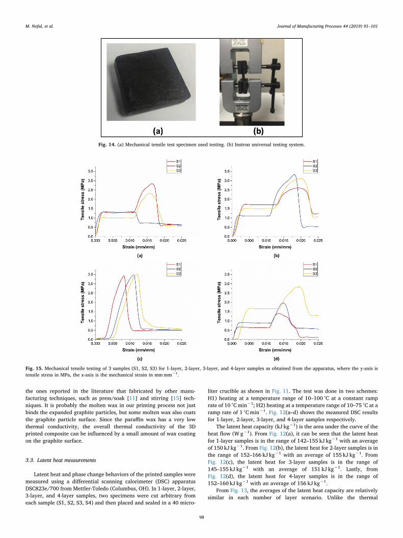
Fig. 14. (a) Mechanical tensile test specimen used testing. (b) Instron universal testing system.
Fig. 15. Mechanical tensile testing of 3 samples (S1, S2, S3) for 1-layer, 2-layer, 3-layer, and 4-layer samples as obtained from the apparatus, where the y-axis istensile stress in MPa, the x-axis is the mechanical strain in mmmm−1.
M. Nofal, et al. Journal of Manufacturing Processes 44 (2019) 91–101
98
conductivity property, latent heat capacity depends on the availableweight of the phase change material – paraffin wax in our case – re-gardless of the structure of the composite. In the 4-layer samples, therange of latent heat capacities was the smallest, compared with theother number of layer scenario. This suggests that when the number oflayers increases, the phase change composition becomes more uniform.Overall, since the specimens were cut arbitrary from each sample, theamount of paraffin wax may be slightly different, which explains thevariation in the measurements in general. It is important to note thatthe pure paraffin wax that was used in this study has a latent heat ca-pacity of ˜200 kJ kg−1. With 80% wax to 20% graphite ratio by weight,the composite latent capacity range suggests a successful utilization ofthe latent heat of paraffin wax.
3.4. Mechanical tensile measurements
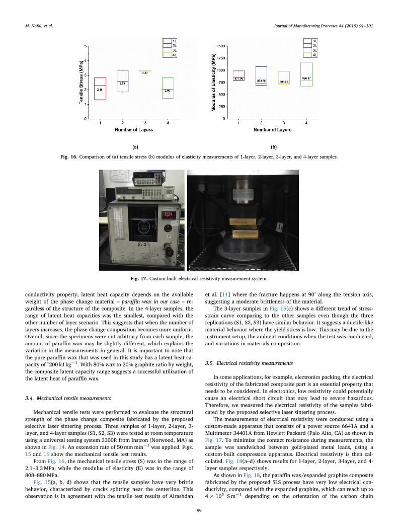
Mechanical tensile tests were performed to evaluate the structuralstrength of the phase change composite fabricated by the proposedselective laser sintering process. Three samples of 1-layer, 2-layer, 3-layer, and 4-layer samples (S1, S2, S3) were tested at room temperatureusing a universal testing system 3300R from Instron (Norwood, MA) asshown in Fig. 14. An extension rate of 50mmmin−1 was applied. Figs.15 and 16 show the mechanical tensile test results.
From Fig. 16, the mechanical tensile stress (S) was in the range of2.1–3.3MPa, while the modulus of elasticity (E) was in the range of808–880MPa.
Fig. 15(a, b, d) shows that the tensile samples have very brittlebehavior, characterized by cracks splitting near the centerline. Thisobservation is in agreement with the tensile test results of Alrashdan
et al. [11] where the fracture happens at 90° along the tension axis,suggesting a moderate brittleness of the material.
The 3-layer samples in Fig. 15(c) shows a different trend of stress-strain curve comparing to the other samples even though the threereplications (S1, S2, S3) have similar behavior. It suggests a ductile-likematerial behavior where the yield stress is low. This may be due to theinstrument setup, the ambient conditions when the test was conducted,and variations in materials composition.
3.5. Electrical resistivity measurements
In some applications, for example, electronics packing, the electricalresistivity of the fabricated composite part is an essential property thatneeds to be considered. In electronics, low resistivity could potentiallycause an electrical short circuit that may lead to severe hazardous.Therefore, we measured the electrical resistivity of the samples fabri-cated by the proposed selective laser sintering process.
The measurements of electrical resistivity were conducted using acustom-made apparatus that consists of a power source 6641A and aMultimeter 34401A from Hewlett Packard (Palo Alto, CA) as shown inFig. 17. To minimize the contact resistance during measurements, thesample was sandwiched between gold-plated metal leads, using acustom-built compression apparatus. Electrical resistivity is then cal-culated. Fig. 18(a–d) shows results for 1-layer, 2-layer, 3-layer, and 4-layer samples respectively.
As shown in Fig. 18, the paraffin wax/expanded graphite compositefabricated by the proposed SLS process have very low electrical con-ductivity, compared with the expanded graphite, which can reach up to4×105 Sm−1 depending on the orientation of the carbon chain
Fig. 16. Comparison of (a) tensile stress (b) modulus of elasticity measurements of 1-layer, 2-layer, 3-layer, and 4-layer samples.
Fig. 17. Custom-built electrical resistivity measurement system.
M. Nofal, et al. Journal of Manufacturing Processes 44 (2019) 91–101
99
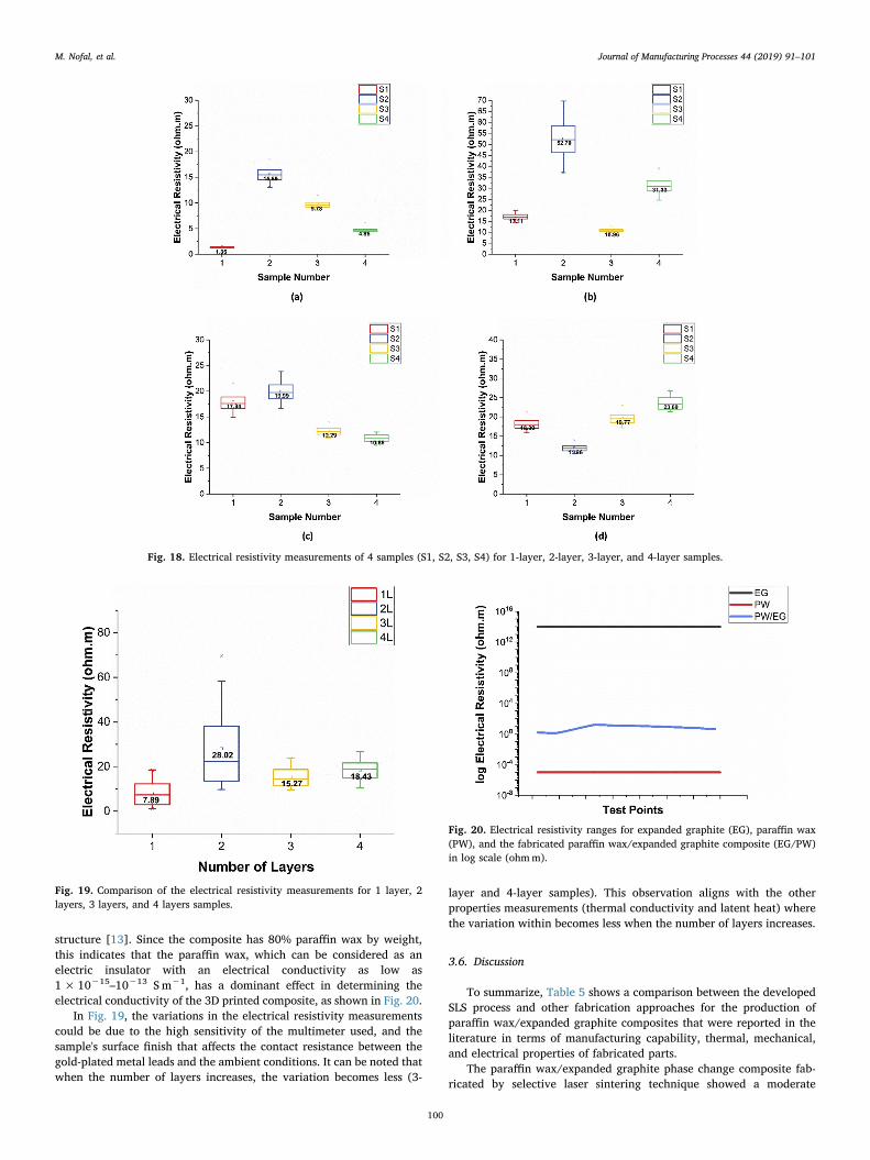
structure [13]. Since the composite has 80% paraffin wax by weight,this indicates that the paraffin wax, which can be considered as anelectric insulator with an electrical conductivity as low as1× 10−15–10−13 S m−1, has a dominant effect in determining theelectrical conductivity of the 3D printed composite, as shown in Fig. 20.
In Fig. 19, the variations in the electrical resistivity measurementscould be due to the high sensitivity of the multimeter used, and thesample's surface finish that affects the contact resistance between thegold-plated metal leads and the ambient conditions. It can be noted thatwhen the number of layers increases, the variation becomes less (3-
layer and 4-layer samples). This observation aligns with the otherproperties measurements (thermal conductivity and latent heat) wherethe variation within becomes less when the number of layers increases.
3.6. Discussion
To summarize, Table 5 shows a comparison between the developedSLS process and other fabrication approaches for the production ofparaffin wax/expanded graphite composites that were reported in theliterature in terms of manufacturing capability, thermal, mechanical,and electrical properties of fabricated parts.
The paraffin wax/expanded graphite phase change composite fab-ricated by selective laser sintering technique showed a moderate
Fig. 18. Electrical resistivity measurements of 4 samples (S1, S2, S3, S4) for 1-layer, 2-layer, 3-layer, and 4-layer samples.
Fig. 19. Comparison of the electrical resistivity measurements for 1 layer, 2layers, 3 layers, and 4 layers samples.
Fig. 20. Electrical resistivity ranges for expanded graphite (EG), paraffin wax(PW), and the fabricated paraffin wax/expanded graphite composite (EG/PW)in log scale (ohmm).
M. Nofal, et al. Journal of Manufacturing Processes 44 (2019) 91–101
100
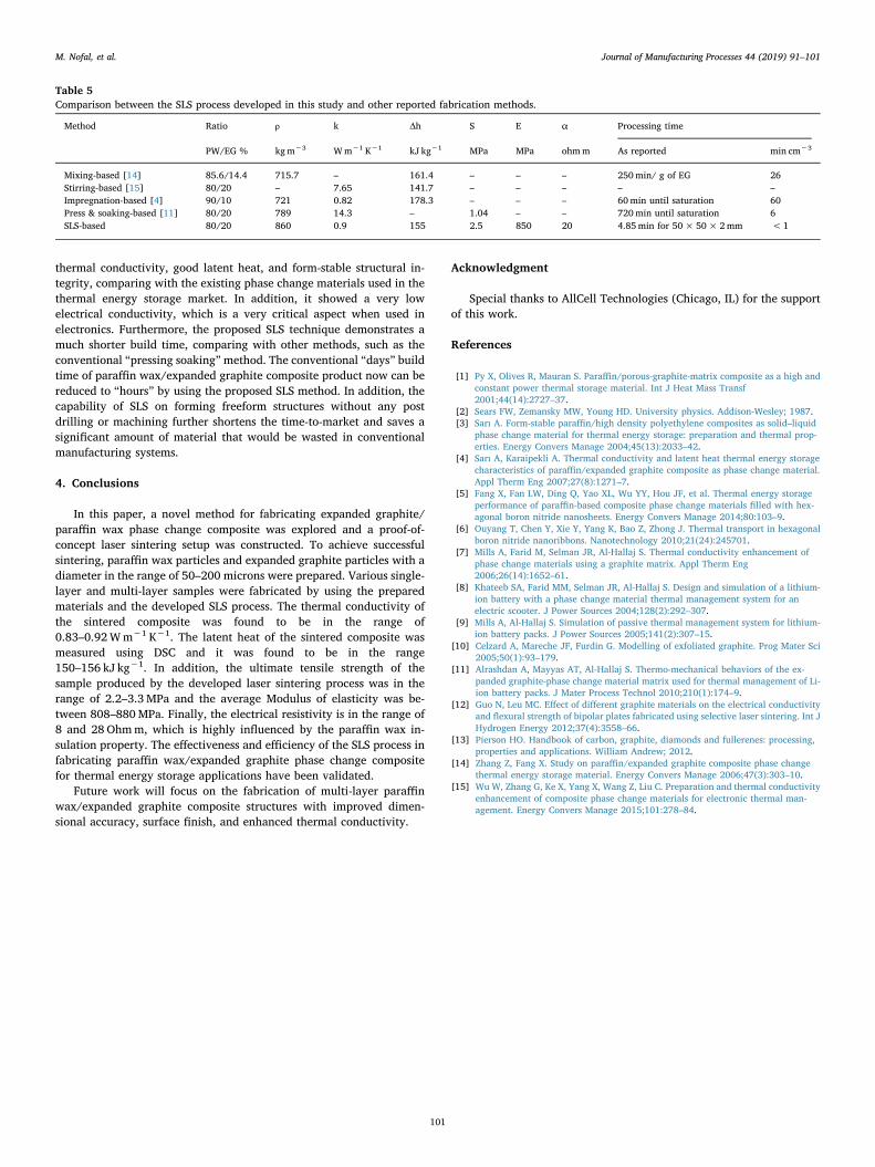
thermal conductivity, good latent heat, and form-stable structural in-tegrity, comparing with the existing phase change materials used in thethermal energy storage market. In addition, it showed a very lowelectrical conductivity, which is a very critical aspect when used inelectronics. Furthermore, the proposed SLS technique demonstrates amuch shorter build time, comparing with other methods, such as theconventional “pressing soaking”method. The conventional “days” buildtime of paraffin wax/expanded graphite composite product now can bereduced to “hours” by using the proposed SLS method. In addition, thecapability of SLS on forming freeform structures without any postdrilling or machining further shortens the time-to-market and saves asignificant amount of material that would be wasted in conventionalmanufacturing systems.
4. Conclusions
In this paper, a novel method for fabricating expanded graphite/paraffin wax phase change composite was explored and a proof-of-concept laser sintering setup was constructed. To achieve successfulsintering, paraffin wax particles and expanded graphite particles with adiameter in the range of 50–200 microns were prepared. Various single-layer and multi-layer samples were fabricated by using the preparedmaterials and the developed SLS process. The thermal conductivity ofthe sintered composite was found to be in the range of0.83–0.92Wm−1 K−1. The latent heat of the sintered composite wasmeasured using DSC and it was found to be in the range150–156 kJ kg−1. In addition, the ultimate tensile strength of thesample produced by the developed laser sintering process was in therange of 2.2–3.3MPa and the average Modulus of elasticity was be-tween 808–880MPa. Finally, the electrical resistivity is in the range of8 and 28 Ohmm, which is highly influenced by the paraffin wax in-sulation property. The effectiveness and efficiency of the SLS process infabricating paraffin wax/expanded graphite phase change compositefor thermal energy storage applications have been validated.
Future work will focus on the fabrication of multi-layer paraffinwax/expanded graphite composite structures with improved dimen-sional accuracy, surface finish, and enhanced thermal conductivity.
Acknowledgment
Special thanks to AllCell Technologies (Chicago, IL) for the supportof this work.
References
[1] Py X, Olives R, Mauran S. Paraffin/porous-graphite-matrix composite as a high andconstant power thermal storage material. Int J Heat Mass Transf2001;44(14):2727–37.
[2] Sears FW, Zemansky MW, Young HD. University physics. Addison-Wesley; 1987.[3] Sarı A. Form-stable paraffin/high density polyethylene composites as solid–liquid
phase change material for thermal energy storage: preparation and thermal prop-erties. Energy Convers Manage 2004;45(13):2033–42.
[4] Sarı A, Karaipekli A. Thermal conductivity and latent heat thermal energy storagecharacteristics of paraffin/expanded graphite composite as phase change material.Appl Therm Eng 2007;27(8):1271–7.
[5] Fang X, Fan LW, Ding Q, Yao XL, Wu YY, Hou JF, et al. Thermal energy storageperformance of paraffin-based composite phase change materials filled with hex-agonal boron nitride nanosheets. Energy Convers Manage 2014;80:103–9.
[6] Ouyang T, Chen Y, Xie Y, Yang K, Bao Z, Zhong J. Thermal transport in hexagonalboron nitride nanoribbons. Nanotechnology 2010;21(24):245701.
[7] Mills A, Farid M, Selman JR, Al-Hallaj S. Thermal conductivity enhancement ofphase change materials using a graphite matrix. Appl Therm Eng2006;26(14):1652–61.
[8] Khateeb SA, Farid MM, Selman JR, Al-Hallaj S. Design and simulation of a lithium-ion battery with a phase change material thermal management system for anelectric scooter. J Power Sources 2004;128(2):292–307.
[9] Mills A, Al-Hallaj S. Simulation of passive thermal management system for lithium-ion battery packs. J Power Sources 2005;141(2):307–15.
[10] Celzard A, Mareche JF, Furdin G. Modelling of exfoliated graphite. Prog Mater Sci2005;50(1):93–179.
[11] Alrashdan A, Mayyas AT, Al-Hallaj S. Thermo-mechanical behaviors of the ex-panded graphite-phase change material matrix used for thermal management of Li-ion battery packs. J Mater Process Technol 2010;210(1):174–9.
[12] Guo N, Leu MC. Effect of different graphite materials on the electrical conductivityand flexural strength of bipolar plates fabricated using selective laser sintering. Int JHydrogen Energy 2012;37(4):3558–66.
[13] Pierson HO. Handbook of carbon, graphite, diamonds and fullerenes: processing,properties and applications. William Andrew; 2012.
[14] Zhang Z, Fang X. Study on paraffin/expanded graphite composite phase changethermal energy storage material. Energy Convers Manage 2006;47(3):303–10.
[15] Wu W, Zhang G, Ke X, Yang X, Wang Z, Liu C. Preparation and thermal conductivityenhancement of composite phase change materials for electronic thermal man-agement. Energy Convers Manage 2015;101:278–84.
Table 5Comparison between the SLS process developed in this study and other reported fabrication methods.
Method Ratio ρ k Δh S E α Processing time
PW/EG % kgm−3 Wm−1 K−1 kJ kg−1 MPa MPa ohmm As reported min cm−3
Mixing-based [14] 85.6/14.4 715.7 – 161.4 – – – 250min/ g of EG 26Stirring-based [15] 80/20 – 7.65 141.7 – – – – –Impregnation-based [4] 90/10 721 0.82 178.3 – – – 60min until saturation 60Press & soaking-based [11] 80/20 789 14.3 – 1.04 – – 720min until saturation 6SLS-based 80/20 860 0.9 155 2.5 850 20 4.85min for 50× 50×2mm <1
M. Nofal, et al. Journal of Manufacturing Processes 44 (2019) 91–101
101
Related Documents