HEFAT2014 10 th International Conference on Heat Transfer, Fluid Mechanics and Thermodynamics 14 – 16 July 2014 Orlando, Florida EXPERIMENTAL INVESTIGATION OF A DOUBLE-BED ADSORPTION COOLING SYSTEM FOR APPLICATION IN GREEN BUILDINGS Tso C.Y., Chan K.C. and Chao C.Y.H.* *Author for correspondence Department of Mechanical and Aerospace Engineering, The Hong Kong University of Science and Technology, Hong Kong China E-mail: [email protected] ABSTRACT In this study, an adsorption cooling system with silica gel as the adsorbent and water as the adsorbate was built and the system performance was studied experimentally under various working conditions. The adsorption cooling system contains two adsorbers in a u-tube and circular plate fin structure, an evaporator (chilled water tank), two condensers, one heating and one cooling water tank, and is equipped with measuring instruments and supplementary system components. Under the standard operation condition: adsorber cooling water inlet temperature about 34 °C, desorption temperature of 80 °C, evaporating temperature of 14 °C and adsorption/desorption phase time of 15 minutes, the coefficient of performance (COP) of the adsorption cooling system was recorded at about 0.3 while the specific cooling power (SCP) was about 39.1 W/kg. INTRODUCTION Global warming and energy shortage issues have been receiving great attention in recent years all over the world. Among various technologies being developed to alleviate these problems, adsorption cooling systems powered by solar energy or waste heat have good potential in terms of saving energy. These systems need neither CFCs nor HCFCs as the working fluid and limited electricity is needed to drive them [1-4]. Silica gel - water as an adsorbent - adsorbate pair is widely used in adsorption cooling systems since silica gel requires a low regeneration temperature while water has a relatively high latent heat of vaporization. Additionally, this working pair is non-toxic and stable. Although adsorption cooling systems are thought to be very promising for the future application of solar cooling and waste heat recovery, the wide use of this technology is not yet possible due to poor COP values and the high product cost of the systems [5-7]. Many researchers have devoted their work to adsorption refrigeration technology and many studies have been conducted. As part of that research, silica gel – water adsorption cooling systems have been analytically and experimentally investigated [8-10]. Saha et al. [10] experimentally investigated a double- stage, four bed, non-regenerative adsorption chiller powered by solar/waste heat sources between 50 and 70 °C. The prototype studied produces chilled water at 10 °C and has a cooling power of 3.2 kW with a COP of 0.36, when the heat source and heat sink temperatures are 55 and 30 °C, respectively. Boelman et al. [11] experimentally and numerically studied a commercially available silica gel – water adsorption chiller. The highest experimental COP values above 0.4 were obtained with a hot water inlet temperature of 50 °C and cooling water inlet temperature of 20 °C. This study aims at building a thermally driven adsorption cooling system using silica gel – water as the adsorbent – adsorbate pair, using a novel design consisting of a u-tube and circular plate fin structure as the adsorber. Most importantly, the performance of the cooling system in various operating conditions, such as desorption temperature, adsorber cooling water temperature, evaporating temperature, cycle time and heat transfer fluid (water) mass flow rate are investigated. NOMENCLATURE Cp,water [J/kgK] Specific heat capacity of water COP [-] Coefficient of performance m [kg/min] Heat transfer fluid mass flow rate P [Pa] Pressure Q [W] Cooling capacity SCP [W/kg] Specific cooling power T [K] Temperature t [second] Time V [-] Valve W X [kg] [kg/kg] Mass Amount adsorbed (mass of water vapour per mass of dry adsorbent) Subscripts ads adsorption amb ambient 549

Welcome message from author
This document is posted to help you gain knowledge. Please leave a comment to let me know what you think about it! Share it to your friends and learn new things together.
Transcript

HEFAT2014
10th
International Conference on Heat Transfer, Fluid Mechanics and Thermodynamics
14 – 16 July 2014
Orlando, Florida
EXPERIMENTAL INVESTIGATION OF A DOUBLE-BED ADSORPTION COOLING
SYSTEM FOR APPLICATION IN GREEN BUILDINGS
Tso C.Y., Chan K.C. and Chao C.Y.H.*
*Author for correspondence
Department of Mechanical and Aerospace Engineering,
The Hong Kong University of Science and Technology,
Hong Kong
China
E-mail: [email protected]
ABSTRACT
In this study, an adsorption cooling system with silica gel
as the adsorbent and water as the adsorbate was built and the
system performance was studied experimentally under various
working conditions. The adsorption cooling system contains
two adsorbers in a u-tube and circular plate fin structure, an
evaporator (chilled water tank), two condensers, one heating
and one cooling water tank, and is equipped with measuring
instruments and supplementary system components. Under the
standard operation condition: adsorber cooling water inlet
temperature about 34 °C, desorption temperature of 80 °C,
evaporating temperature of 14 °C and adsorption/desorption
phase time of 15 minutes, the coefficient of performance (COP)
of the adsorption cooling system was recorded at about 0.3
while the specific cooling power (SCP) was about 39.1 W/kg.
INTRODUCTION Global warming and energy shortage issues have been
receiving great attention in recent years all over the world.
Among various technologies being developed to alleviate these
problems, adsorption cooling systems powered by solar energy
or waste heat have good potential in terms of saving energy.
These systems need neither CFCs nor HCFCs as the working
fluid and limited electricity is needed to drive them [1-4].
Silica gel - water as an adsorbent - adsorbate pair is widely
used in adsorption cooling systems since silica gel requires a
low regeneration temperature while water has a relatively high
latent heat of vaporization. Additionally, this working pair is
non-toxic and stable. Although adsorption cooling systems are
thought to be very promising for the future application of solar
cooling and waste heat recovery, the wide use of this
technology is not yet possible due to poor COP values and the
high product cost of the systems [5-7].
Many researchers have devoted their work to adsorption
refrigeration technology and many studies have been conducted.
As part of that research, silica gel – water adsorption cooling
systems have been analytically and experimentally investigated
[8-10]. Saha et al. [10] experimentally investigated a double-
stage, four bed, non-regenerative adsorption chiller powered by
solar/waste heat sources between 50 and 70 °C. The prototype
studied produces chilled water at 10 °C and has a cooling
power of 3.2 kW with a COP of 0.36, when the heat source and
heat sink temperatures are 55 and 30 °C, respectively.
Boelman et al. [11] experimentally and numerically studied a
commercially available silica gel – water adsorption chiller.
The highest experimental COP values above 0.4 were obtained
with a hot water inlet temperature of 50 °C and cooling water
inlet temperature of 20 °C. This study aims at building a
thermally driven adsorption cooling system using silica gel –
water as the adsorbent – adsorbate pair, using a novel design
consisting of a u-tube and circular plate fin structure as the
adsorber. Most importantly, the performance of the cooling
system in various operating conditions, such as desorption
temperature, adsorber cooling water temperature, evaporating
temperature, cycle time and heat transfer fluid (water) mass
flow rate are investigated.
NOMENCLATURE Cp,water [J/kgK] Specific heat capacity of water
COP [-] Coefficient of performance
m [kg/min] Heat transfer fluid mass flow rate
P [Pa] Pressure
Q [W] Cooling capacity SCP [W/kg] Specific cooling power
T [K] Temperature
t [second] Time V [-] Valve
W
X
[kg]
[kg/kg]
Mass
Amount adsorbed (mass of water vapour per mass of dry adsorbent)
Subscripts ads adsorption
amb ambient
549

chill chilled water cond condenser/condensation
cool cooling water in adsorber/desorber
cycle cycle des
eva
hmr hot
max
in out
desorption
evaporator/evaporation
heat and mass recovery hot water
maximum
inlet outlet
WORKING PRINCIPLE OF THE ADSORPTION COOLING SYSTEM
The adsorption cooling system can be compared to
conventional cooling systems for air conditioners, chillers or
refrigerators but with the electrically powered mechanical
compressor being replaced by an adsorber. The system can be
powered by a rather low driven temperature, e.g. waste heat or
solar energy, which makes it attractive in terms of saving
electrical energy. In addition, the adsorption cooling system
can be operated without moving parts; only solenoid vacuum
valves are used. This results in low vibration, mechanical
simplicity, high reliability and a very long life span [12-14].
The adsorption-desorption process is described in an
isostere diagram. The ideal cycles consist of four steps as
shown in Figure 1:
1. Isosteric heating: the adsorbent is heated without
changing the loading of water vapor.
2. Desorption process: the adsorbent is heated and
regenerated at the condenser pressure (Pcond). The adsorbent
changes its loading from the maximum value Xmax (taking X =
0.2 as an example) to the minimum loading Xmin (taking X = 0.1
as an example). In this process, the desorption heat (Qdes) is
taken up. At the same time, the desorbed refrigerant is
condensed in the condenser releasing the heat of condensation
at the temperature Tcond.
3. Isosteric cooling: the regenerated adsorbent is cooled to
reach the conditions for the following adsorption process. The
loading stays constant at Xmin.
4. Isobaric adsorption: the adsorbent adsorbs refrigerant at
the pressure Peva of the evaporator. In this process, the loading
increases from Xmin to Xmax and the heat of adsorption is
released. The refrigerant evaporates in the evaporator,
producing the cooling effect.
As the adsorbent cannot be pumped, these steps have to be
carried out consecutively. This implies that the system only
produces cooling intermittently during the adsorption step. In
order to provide quasi-continuous cooling, a laboratory
prototype of a double bed adsorption cooling system was
designed and built, and its performance analyzed
experimentally under different working conditions. A
schematic diagram of the prototype is shown in Figure 2.
Figure 1 Adsorption cycle in an isostere diagram
Figure 2 Schematic diagram of the laboratory prototype
adsorption cooling system [P: pressure transducers; T: K-type thermocouples; F: flow meters; V1:
manual vacuum ball valve; V2: manual ball valve; V3-V8: solenoid
vacuum valves; V9-V19: solenoid valves with non-return values
connected in series; pump 1 - pump 4: circulation water pumps].
The cycle has three modes; adsorption mode, heat and mass
recovery mode and desorption mode. The adsorption mode and
desorption mode run alternately while the heat and mass
recovery mode runs after the adsorption mode or desorption
mode.
In adsorption mode (adsorber 1 as a target), as shown in
Figure 2, valves V2, V3, V4, V7, V8, V9, V12, V13, V15 and
V16 are opened, while valves V5, V6, V10, V11, V14, V17,
V18 and V19 are closed. Valve 1 is opened only before
running the system in order to lower the pressure inside the
adsorbers and chilled water tank. After the system starts to run
normally, the vacuum pump is removed. In this mode, adsorber
1 adsorbs while adsorber 2 desorbs. In the adsorption-
evaporation process, refrigerant (water) in the chilled water
tank evaporates at the evaporation temperature, Teva, and the
seized heat, Qeva is removed from the chilled water tank. The
evaporated vapor is adsorbed by the silica gel adsorbent in
550

adsorber 1, where cooling water removes the adsorption heat,
Qads. The desorption-condensation process takes place at
pressure Pcond. The desorber (adsorber 2) is heated to the
temperature (Tdes) by Qdes, provided by the heat (e.g. waste heat)
in the hot water tank. The resulting refrigerant vapor is cooled
to temperature (Tcond) in the condenser, which removes the heat,
Qcond. The condensed refrigerant returns to the evaporator via
the U-tube connecting the condenser and evaporator to
complete the cycle. After running in adsorption mode for a
period of time, the cycle is continued by changing into heat and
mass recovery mode.
In the heat and mass recovery mode, as shown in Figure 2,
valves V2, V4, V5, V6, V7, V18 and V19 are opened while V3,
V8, V9, V10, V11, V12, V13, V14, V15, V16 and V17 are
closed. The heat recovery process can recover some heat
during mode switching between the adsorber and the desorber.
In this process, the heat transfer fluid flows through two
adsorbers to recover heat via their temperature difference. By
circulating the thermal fluid between the two adsorbers
adiabatically, the energy efficiency can be increased
significantly [15]. Mass recovery is also beneficial to improve
the adsorption cycled refrigerant (water vapor) of an adsorption
cooling system. In a typical mass recovery process, the
pressure of adsorber 2 at the end of the desorption process is
higher than at the end of the adsorption process. Next, the high
pressure adsorber needs to be cooled and depressurized while
the low pressure adsorber needs to be heated and pressurized.
Then the two adsorbers may be directly interconnected with a
simple device and the refrigerant vapor will flow from the high-
pressure bed to the low pressure bed. The pressure of adsorber
2 decreases due to mass outflow and this will again cause
desorption of adsorber 2. Meanwhile, the pressure of adsorber
1 increases due to mass inflow and will cause further
adsorption. The process continues until the two adsorbers
reach the same pressure. Then the connection is broken and
each adsorber goes on with the heating and cooling process just
as in the adsorption mode and desorption mode. This mass
recovery process is expected to accelerate the circulation and
enhance the cycle cooling power, as it only involves direct
mass flow while the pressure balance is much faster than the
temperature balance via the heat-transfer medium.
Lastly, in the desorption mode (adsorber 1 as a target);
valves V2, V3, V5, V6, V8, V10, V11, V13, V14 and V17 are
opened while V4, V7, V9, V12, V15, V16, V18 and V19 are
closed. In this mode, adsorber 2 adsorbs while adsorber 1
desorbs. Again, after running in desorption mode for a period
of time, the cycle returns to the heat and mass recovery mode.
After that, the cycle goes to adsorber 1 adsorbs mode while
adsorber 2 desorbs.
DESCRIPTION OF THE ADSORPTION COOLING SYSTEM
The adsorber is the most important element of an adsorption
cooling system. Because of the poor thermal conductivity of
the adsorbent materials commonly used in adsorption cooling
systems, the heat and mass transfer abilities of the adsorbers
should be considered carefully during the design process. In
this study, an adsorber was designed and built based on this
consideration. Each adsorber consists of 14 cylindrical shell
units, covered with a stainless steel metal screen mesh with a
nominal pore size of 74 microns. Figure 3 shows a photograph
of a cylindrical shell unit (u-tube structure). The adsorbents are
inserted between the circular fins. Each adsorber can be filled
with 9 kg of silica gel adsorbent material. The silica gel
adsorbent having an average particle size 0.42 – 2 mm was
bought from NACALAI TESQUE, INC, Kyoto, Japan. The
isotherm of this silica gel is well-known, of which the
adsorption capacity is directly proportional to the vapour
pressure within the operation range of adsorption cooling
systems. Two thermocouples are located in the adsorber to
record the temperature of the adsorbents. 14 cylindrical shells
are put together into a large cylindrical vacuum chamber
(adsorber) and are connected in series by copper piping as
shown in Figure 4.
Figure 3 One cylindrical shell unit (u-tube structure) used in
the adsorber
Figure 4 14 cylindrical shells in a large vacuum chamber
(adsorber)
Control system and calculations
A 2.2 kW electrical immersion heater is inserted into the hot
water tank in order to generate the heat for the desorption
process of the adsorption cooling system. An electrical heater
is used instead of solar thermal or a waste heat capturing
551

system because the main interest of this study is the
performance of the silica gel adsorbents under various well-
controlled operating conditions. A PID temperature controller
was used to control the temperature inside the hot water tank to
prevent overheating and to control the desorption temperature
(hot water inlet temperature) for different operating conditions.
All the thermocouple and pressure transducer measurements
were recorded by data acquisition (DAQ) devices from
National Instrument. The thermocouple signals were recorded
by SCXI-1102 32-Channel Thermocouple/Voltage Input
Module with SCXI-1324 terminal block equipped in the SCXI-
1001 chassis, while the pressure transducer signals were
recorded by USB-6229 USB DAQ device connected to a
computer. NI LabVIEW (version 8.6) software was used to
build a virtual DAQ program. Data was recorded every 5
seconds and stored in the computer’s hard disk. Another
LabVIEW program was built to control the solenoid vacuum
valves through a SCXI-1160 16-Channel General-Purpose
Relay Module on SCXI-1001. The program can control the
valves individually or in a group, allowing phase changes to be
completed in one click.
The standard operating conditions for the adsorption
cooling system are shown in Table 1 while varied operating
conditions are listed in Table 2.
Table 1 Standard operating condition for the adsorption
cooling system
Parameters Symbol Value unit
Hot water inlet temperature Thot,in 80 oC
Hot water mass flow rate hotm 8 kg/min
Adsorber cooling water inlet
temperature
Tcool,in 34 oC
Adsorber cooling water mass
flow rate coolm 8 kg/min
Chilled water inlet temperature Tchill,in 14 oC
Chilled water mass flow rate chillm 3.6 kg/min
Adsorption/desorption phase
time
tcycle 15 mins
Heat and mass recovery time thmr 50 seconds
Table 2 Varied operating conditions for the adsorption
cooling system
Parameters Symbol Value unit
Hot water inlet
(desorption) temperature
Thot,in 55, 60, 65,
70, 75, 80,
85, 90, 95
oC
Hot water mass flow rate hotm 4, 6, 8, 10 kg/min
Adsorber cooling water
inlet temperature
Tcool,in 20.5, 27,
32.5, 34
oC
Adsorber cooling water
mass flow rate coolm 4, 6, 8, 10 kg/min
Chilled water inlet
temperature
Tchill,in 8, 10, 12, 14,
16, 18, 20
oC
Chilled water mass flow
rate chillm 1.6, 3.6, 5.6,
7.6
kg/min
Adsorption/desorption
phase time
tcycle 5, 7.5, 10,15,
20, 25, 30
mins
Equation (1) is used to calculate the coefficient of
performance (COP) of the experimental prototype for different
operating conditions. Specifically, this refers to the time-
average COP:
0
0
cycle
cycle
tchill
des
t
Qdt
QCOP
dt
(1)
where Qchill and Qdes represent the cooling output power and
thermal input power, respectively. They are calculated from
the measured flow rates, the isobaric specific heat capacities,
and inlet and outlet temperatures of the chilled water tank
(evaporator) and hot water tank as shown in equation (2) and
equation (3) below, respectively:
, , ,( )chill chill p water chill in chill outQ m c T T (2)
, , ,( )des hot p water hot in hot outQ m c T T (3)
where chillm and
hotm represent the mass flow rates of chilled
water and hot water respectively. Equation (4) is used to
calculate the specific cooling power (SCP) of the adsorption
cooling systems:
chillQSCP
W (4)
where W represents the weight of the silica gel adsorbent.
RESULTS AND DISCUSSIONS The performance of the prototype was investigated
experimentally under various conditions. A photograph of the
whole adsorption cooling system prototype is shown in Figure
5. An isothermal water circulator was used to provide a steady
chilled water inlet temperature to the adsorption cooling system
enabling an accurate evaporating temperature to be obtained
during the measurement. Since the thermal input power was
obtained by the temperature difference between the inlet and
outlet of the hot water tank, heat loss to the ambient
environment is included in the calculation. The energy loss
was mainly from the adsorbers, hot and cooling water tanks,
piping system through which heat transfer fluid (water)
circulates, and heat capacities of the metal and heat transfer
fluid (water).
552

Figure 5 A prototype of the adsorption cooling system
[Remarks: 1: cooling water tank; 2: isothermal water
circulator; 3: chilled water tank (evaporator); 4: Adsorber 1; 5:
Adsorber 2; 6: hot water tank; 7: condenser; 8: control system.]
Effect of desorption temperature on the SCP and COP
The desorption temperature is one major factor affecting the
performance of adsorption cooling systems. Figure 6 shows the
effect of the desorption temperature on the SCP and COP.
Theoretically, the COP should increase, along with the
desorption temperature, to a specific temperature and thereafter
remain unchanged as the temperature continues to rise. As
shown in Figure 6, the COP increases when the desorption
temperature is lower than 70 °C, but it decreases significantly
for desorption temperatures higher than 70 °C. This can be
attributed to an increase in heat loss at higher desorption
temperatures. For the lower desorption temperatures, the heat
loss is smaller compared with the higher desorption
temperatures. The results of the SCP are in good agreement
with the prediction, increasing monotonically with the
desorption temperature from 55 °C to 95 °C. Since water vapor
is desorbed faster at the higher desorption temperature, the
adsorbent is drier so the driving force for adsorption is higher,
allowing more water vapor to be adsorbed during the next
adsorption process.
However, it should be remembered that the thermal energy
input should actually come from renewable energy (e.g. solar
energy or waste heat) which are free of charge or from natural
resources. Therefore, the thermal COP values shown in this
study are just for reference and comparison with other studies.
In reality, the COP value is meaningless for adsorption cooling
systems. However, SCP is a very important parameter,
indicating how large the adsorption cooling systems are and the
amount of cooling power of the adsorption cooling systems.
Hence, the larger the SCP, the smaller the size of the adsorption
cooling system for the same cooling output. Considering this, a
higher desorption temperature should be selected based on the
results shown in Figure 6. However, a higher desorption
temperature will limit the application value. After considering
the range of low grade waste heat and solar energy, 85 oC is a
suitable desorption temperature for adsorption cooling systems.
Therefore, 85 oC is utilized in the following study as the
desorption temperature for this adsorption cooling system
prototype.
Figure 6 Effect of desorption temperature on the SCP and COP
Effect of adsorption/desorption phase time on the SCP and
COP
Figure 7 shows the effect of adsorption/desorption phase
time on the SCP and COP performance of the adsorption
cooling system. The desorption temperature is set at 85 oC as
suggested previously, while the other conditions are as shown
in Table 1 (except for the adsorption/desorption phase time
since it is the parameter being studied in this section). There
exists a peak between 10 and 15 minutes for the SCP and at
about 15 minutes for the COP. For shorter
adsorption/desorption phase times, the desorption process is
incomplete, leading to diminish the adsorption capacity of silica
gel adsorbent. As a result, the SCP and COP are low at a
shorter phase time. For longer adsorption/desorption phase
times, the SCP decreases due to the rapid diminution of
adsorption capacity of the silica gel adsorbent during the last
few minutes. In short, the adsorption/desorption phase time for
this adsorption cooling system prototype using silica gel as the
adsorbent is about 15 minutes since it not only shows a higher
SCP, but also the COP is maximized.
553

Figure 7 Effect of adsorption/desorption phase time on the
SCP and COP
Effect of the hot water mass flow rate on the SCP and COP
Hot water is used to heat the adsorbent during the
desorption process. More heat can be transferred to the
adsorbers over the same duration with a higher hot water mass
flow rate, allowing more water vapor to be desorbed out.
Hence, a higher hot water mass flow rate should result in higher
COP and SCP. In the experimental results, the COP, however,
decreased after 8 kg/min in terms of the hot water mass flow
rate as shown in Figure 8. This is simply because more heat is
lost to the surroundings under higher hot water mass flow rate.
The effect is similar to that caused by changing the desorption
temperature as previously discussed. For the lowest hot water
flow rate, 4 kg/min, the COP also decreases, possibly because
the adsorber cannot be desorbed effectively under this slow
flow rate. The effect on SCP is also shown in Figure 8. There
is almost no change in SCP and it can be concluded that the hot
water mass flow rate does not have an apparent effect on SCP.
Therefore, in order to optimize the COP value, 8 kg/min is
chosen as the hot water mass flow rate for this adsorption
cooling system prototype.
Figure 8 Effect of hot water mass flow rate on the SCP and
COP
Effect of cooling water inlet temperature on the SCP and
COP
The cooling water inlet temperature is one decisive factor
on the performance of adsorption cooling systems because it
influences not only the condensation process but also the
adsorption process. A high cooling water inlet temperature
results in a high inlet temperature supply to the condenser and
adsorption chamber. Consequently, both the desorption and
adsorption process performance deteriorates, losing more
refrigerating power. Figure 9 shows the effect of cooling water
inlet temperature on the SCP and COP. The lower cooling
water inlet temperature, the higher SCP and COP since more
water vapour is adsorbed by the silica gel adsorbent at a lower
temperature for a given cycle time. To save energy when
removing the adsorption heat, it is desirable to use cooling
water at room temperature. However, due to the operation of a
water pump, the cooling water inlet temperature averages 27 oC.
Under this condition, the SCP value can still be achieved at
about 68 W/kg with the COP about 0.3.
Figure 9 Effect of cooling water inlet temperature on the SCP
and COP
Effect of the cooling water mass flow rate on the SCP and
COP
As previously discussed, cooling water is used to cool the
adsorber during the adsorption process because adsorption of
adsorbate (water vapor) generates heat. The adsorber also has
to be cooled after the high temperature desorption process. If
the temperature of the adsorber can be decreased faster and
maintained at a low level, a higher SCP and COP will be
obtained. Figure 10 shows the influence of cooling water mass
flow rate on the performance of SCP and COP. It was found
that the COP increases slightly from 4 kg/min to 10 kg/min.
This increase, however, is relatively small. Regarding the SCP,
it seems to be steady after the cooling water mass flow rate of 7
kg/min. Considering this, 7 kg/min was chosen as the cooling
water mass flow rate for this adsorption cooling system.
554
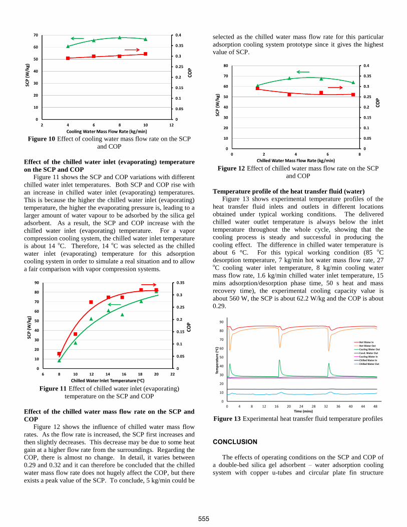
Figure 10 Effect of cooling water mass flow rate on the SCP
and COP
Effect of the chilled water inlet (evaporating) temperature
on the SCP and COP
Figure 11 shows the SCP and COP variations with different
chilled water inlet temperatures. Both SCP and COP rise with
an increase in chilled water inlet (evaporating) temperatures.
This is because the higher the chilled water inlet (evaporating)
temperature, the higher the evaporating pressure is, leading to a
larger amount of water vapour to be adsorbed by the silica gel
adsorbent. As a result, the SCP and COP increase with the
chilled water inlet (evaporating) temperature. For a vapor
compression cooling system, the chilled water inlet temperature
is about 14 oC. Therefore, 14
oC was selected as the chilled
water inlet (evaporating) temperature for this adsorption
cooling system in order to simulate a real situation and to allow
a fair comparison with vapor compression systems.
Figure 11 Effect of chilled water inlet (evaporating)
temperature on the SCP and COP
Effect of the chilled water mass flow rate on the SCP and
COP
Figure 12 shows the influence of chilled water mass flow
rates. As the flow rate is increased, the SCP first increases and
then slightly decreases. This decrease may be due to some heat
gain at a higher flow rate from the surroundings. Regarding the
COP, there is almost no change. In detail, it varies between
0.29 and 0.32 and it can therefore be concluded that the chilled
water mass flow rate does not hugely affect the COP, but there
exists a peak value of the SCP. To conclude, 5 kg/min could be
selected as the chilled water mass flow rate for this particular
adsorption cooling system prototype since it gives the highest
value of SCP.
Figure 12 Effect of chilled water mass flow rate on the SCP
and COP
Temperature profile of the heat transfer fluid (water)
Figure 13 shows experimental temperature profiles of the
heat transfer fluid inlets and outlets in different locations
obtained under typical working conditions. The delivered
chilled water outlet temperature is always below the inlet
temperature throughout the whole cycle, showing that the
cooling process is steady and successful in producing the
cooling effect. The difference in chilled water temperature is
about 6 °C. For this typical working condition (85 oC
desorption temperature, 7 kg/min hot water mass flow rate, 27 oC cooling water inlet temperature, 8 kg/min cooling water
mass flow rate, 1.6 kg/min chilled water inlet temperature, 15
mins adsorption/desorption phase time, 50 s heat and mass
recovery time), the experimental cooling capacity value is
about 560 W, the SCP is about 62.2 W/kg and the COP is about
0.29.
Figure 13 Experimental heat transfer fluid temperature profiles
CONCLUSION
The effects of operating conditions on the SCP and COP of
a double-bed silica gel adsorbent – water adsorption cooling
system with copper u-tubes and circular plate fin structure
555

adsorbers has been experimentally investigated. The following
conclusions are drawn from the foregoing discussion: 1. The system performance is strongly dependent on the
operating conditions such as desorption temperature,
cooling water inlet temperature, chilled water inlet
(evaporating) temperature and adsorption/desorption
phase times. However, the system performance does
not hugely depend on the flow rate of the heat transfer
fluid (water).
2. In order to obtain optimal performance, an appropriate
adsorption/desorption phase time should be selected.
There exists a maxima SCP value with the
adsorption/desorption phase time of about 15 minutes
under the operating conditions in this study.
3. Under the standard operating condition, a cooling
power of 352 W and a COP of 0.3 can be obtained.
The corresponding SCP is about 39.1 W/(kg silica
gel). With slightly higher desorption temperature (85 oC) along with a lower cooling water inlet temperature
(27 oC), a SCP of 68 W/kg can be achieved, making
about 74% improvement compared with the standard
operation condition.
ACKNOWLEDGEMENT
Funding sources for this research are provided by the
Innovation and Technology Support Programme via account
ITS/175/11FP, and by the Hong Kong Research Grant Council
via General Research Fund account 611212.
REFERENCES [1] Saha B.B., Koyama S., Kashiwagi T., Akisawa A., Ng K.C., and
Chua H.T., Waste heat driven dual-mode, multi-stage, multi-bed
regenerative adsorption system, International Journal of
Refrigeration, Vol. 26, 2003, pp. 749-757
[2] Chan K.C., Chao C.Y.H., Sze-To G.N., and Hui K.S., Performance
predictions for a new zeolite 13X/CaCl2 composite adsorbent for
adsorption cooling systems, International Journal of Heat and Mass
Transfer, Vol. 55, 2012, pp. 3214-3224
[3] Tso C.Y., and Chao C.Y.H., Activated carbon, silica-gel and
calcium chloride composite adsorbents for energy efficient solar
adsorption cooling and dehumidification systems, International
Journal of Refrigeration, Vol. 35, 2012, pp. 1626-1638
[4] Tso C.Y., Chao C.Y.H., and Fu S.C., Performance analysis of a
waste heat driven activated carbon based composite adsorbent –
water adsorption chiller using simulation model, Internal Journal of
Heat and Mass Transfer, Vol. 55, 2012, pp. 7596-7610
[5] Miyazaki T., Akisawa A., and Saha B.B., The performance
analysis of a novel dual evaporator type three-bed adsorption chiller,
International Journal of Refrigeration, Vol.33, 2010, pp. 276-285
[6] Solmus I., Kaftanoglu B., Yamali C., and Baker D., Experimental
investigation of a natural zeolite-water adsorption cooling unit,
Applied Energy, Vol. 88, 2011, pp. 4206-4213
[7] Wang Q., Gao X., Xu J.Y., Maiga A.S., and Chen G.M.,
Experimental investigation on a fluidized-bed adsorber/desorber for
the adsorption refrigeration system, International Journal of
Refrigeration, Vol. 35, 2012, pp. 694-700
[8] Zhai X.Q., and Wang R.Z., Experimental investigation and
performance analysis on a solar adsorption cooling system
with/without heat storage, Applied Energy, Vol. 87, 2010, pp. 824-
835
[9] Zhai X.Q., and Wang R.Z., Experimental investigation and
theoretical analysis of the solar adsorption cooling system in a green
building, Applied Thermal Engineering, Vol. 29, 2009, pp. 17-27
[10] Saha B.B., Akisawa A., and Kashiwagi T., Solar/waste heat
driven two-stage adsorption chiller: the prototype, Renewable
Energy, Vol. 23, 2001, pp. 93-101
[11] Boelman E.C., Saha B.B., and Kashiwagi T., Experimental
investigation of a silica gel –water adsorption refrigeration cycle –
The influence of operating conditions on cooling output and COP,
ASHRAE Transactions: Research, Vol.101, 1995, pp. 358-366
[12] Sekret R., and Turski M., Research on an adsorption cooling
system supplied by solar energy, Energy and Buildings, Vol. 51,
2012, pp. 15-20
[13] El-Sharkawy I.I., Saha B.B., Koyama S., He J., Ng K.C., and Yap
C., Experimental investigation on activated carbon-ethanol pair for
solar powered adsorption cooling applications, International
Journal of Refrigeration, Vol. 31, 2008, pp. 1407-1413
[14] Solmus I., Rees D.A.S., Yamali C., Baker D., and Kaftanoglu B.,
Numerical investigation of coupled heat and mass transfer inside the
adsorbent bed of an adsorption cooling unit, International Journal
of Refrigeration, Vol. 35, 2012, pp. 652-662
[15] Pons M., Analysis of the adsorption cycles with thermal
regeneration based on the entropic mean temperatures, Applied
Thermal Engineering, Vol. 17, 1997, pp. 615-627
556
Related Documents