1 23 Materials and Structures ISSN 1359-5997 Volume 44 Number 2 Mater Struct (2010) 44:517-527 DOI 10.1617/ s11527-010-9646-0 Experimental behaviour of reinforced concrete elements repaired with polymer- modified cementicious mortar

Welcome message from author
This document is posted to help you gain knowledge. Please leave a comment to let me know what you think about it! Share it to your friends and learn new things together.
Transcript

1 23
Materials and Structures ISSN 1359-5997Volume 44Number 2 Mater Struct (2010) 44:517-527DOI 10.1617/s11527-010-9646-0
Experimental behaviour of reinforcedconcrete elements repaired with polymer-modified cementicious mortar

1 23
Your article is protected by copyright and all
rights are held exclusively by RILEM. This e-
offprint is for personal use only and shall not
be self-archived in electronic repositories.
If you wish to self-archive your work, please
use the accepted author’s version for posting
to your own website or your institution’s
repository. You may further deposit the
accepted author’s version on a funder’s
repository at a funder’s request, provided it is
not made publicly available until 12 months
after publication.
ORIGINAL ARTICLE
Experimental behaviour of reinforced concrete elementsrepaired with polymer-modified cementicious mortar
Carlo Pellegrino • Francesca da Porto •
Claudio Modena
Received: 11 October 2008 / Accepted: 7 July 2010 / Published online: 24 July 2010
� RILEM 2010
Abstract This paper presents the results of experi-
mental tests on flexural behaviour of reinforced
concrete beams repaired by polymer-modified mortar.
Tests were repeated varying repair thickness, which
included or did not include the steel reinforcement.
Also the position of repair mortar was varied, as it was
carried out either in the tension or compression region.
Finally, the reinforcement ratios of beam sections were
also varied. Results were compared with those from
control beams, which were tested in non-damaged,
non-repaired conditions. Thick repairs that include
the longitudinal reinforcement can restore the load-
bearing capacity and ductility of non-damaged control
beams, whether they are applied in the tension or in the
compression region. Thin repairs in tension, which
substitute the concrete cover, but do not include the
reinforcement, can even decrease the load bearing
capacity and ductility of the beam, whereas thin repairs
in compression are more effective than those in
tension.
Keywords Reinforced concrete �Repair mortars � Interface � Cracking
1 Introduction
Rehabilitation and strengthening of reinforced con-
crete structural elements is a common task for
existing constructions. Strengthening of a structural
element is aimed at increasing or restoring the load
bearing capacity, due to changes in conditions of use
(e.g. increased loading) or deterioration and damage
of the concrete structure (for example due to envi-
ronmental conditions or seismic events). Several
materials and methods are available for strengthening
reinforced concrete elements, such as adding or
applying mortar; spraying concrete or mortar; inject-
ing or filling cracks, voids and interstices; adding
reinforcing steel bars; installing bonded rebars; post-
tensioning; bonding steel plates or fibre reinforced
polymers (FRP) sheets/plates and others [4]. In
particular, externally bonded FRP sheets/plates have
found increasingly wide applications in civil engi-
neering due to their high strength-to-weight ratio and
high corrosion resistance. A number of experimental
programs and analytical studies have been developed
in the last few years at the University of Padova on
flexural [14, 20], shear [11–13] and bond behavior
[15, 16] of FRP strengthened elements.
Recently, Jumaat et al. [6] made a review of various
repair materials and techniques for reinforced concrete
beams, and Engindeniz et al. [2] dealt with the same
subject in the particular case of non-seismically
designed reinforced concrete beam-column joints.
The formers concluded that the effectiveness of repairs
C. Pellegrino (&) � F. da Porto � C. Modena
Department of Structural and Transportation Engineering,
University of Padova, Via Marzolo 9, 35131 Padova, Italy
e-mail: [email protected]
Materials and Structures (2011) 44:517–527
DOI 10.1617/s11527-010-9646-0
Author's personal copy
depends on the characteristics of repairing materials,
the method of application, the property matching
between old concrete and new material, the preparation
of substrates and use of bonding agents. According to
them, cement based materials, new concrete or mortar,
are more suitable than other materials for concrete
repair [6].
The main aims of cementicious repair of beams in
tension or compression regions under static loadings
are the increase of stiffness to reduce deflections
under serviceability loading conditions, and the
reduction of crack amplitudes to increase beam
durability. However, some issues related to this kind
of technique, such as the choice of the repair material
properties and its position and thickness, with the aim
of improving the compatibility and effectiveness of
the intervention, are still subjects of research.
Emberson and Mays [1] carried out one of the first
experimental studies on the influence of mechanical
and physical properties of repair systems, applied on
either the compression or tension regions of rein-
forced concrete beams subjected to short term static,
long term creep and cyclic loading. They used nine
different repair materials, among which epoxy,
cementicious, and polymer-modified mortars. The
results showed that properties of applied materials
should be as close as possible to substrate concrete.
Modules of elasticity should lay within a range of
±10 kN/mm2, whereas tensile strength of the repair
materials should be higher than substrate concrete.
Hassan et al. [5] tested the compatibility of cementi-
cious, polymer, and polymer modified mortar repairs
to concrete. They also concluded that mismatch in
elastic modules reduces the load carrying capacity of
the combined system. High shrinkage of cementi-
cious repairs also affects the effectiveness of repairs,
whereas polymer-modified mortars, due to reduced
shrinkage and compatibility of elastic modules, are
the most appropriate repair materials. Mangat and
O’Flaherty [8] applied seven different ordinary and
polymer-modified cementicious materials, on two
existing bridges. The case studies showed that repairs
with stiff materials were more efficient than others,
which is in partial disagreement with the results of
other authors. However, differences in elastic mod-
ules were all included in the range given by
Emberson and Mays [1]. Furthermore, the most
performing materials were characterized by the
lowest shrinkage properties.
Rı́o et al. [18] tested beams designed to fail in
flexure, after localised artificial corrosion at midspan
and localised patch-repair with three types of mortar
(cement based, epoxy resin binder, and polymer mod-
ified mortar). They demonstrated that load-bearing
capacity of the repaired elements is generally slightly
lower than the reference, non-damaged beam, but
higher than beams damaged by corrosion. In this
case, repair should be deemed effective. They also
concluded that the mechanical properties of the repair
materials should be close to those of the parent
concrete. Park and Yang [10] tested eight beams
repaired in the tension region with ordinary Portland
and polymer-modified cement mortar. They varied
reinforcement ratio and repair length. Although
ordinary Portland cement repairs gave acceptable
results, the polymer-modified repairs offered the best
results in terms of load bearing capacity, failure mode
and ductility. Shannag and Al-Ateek [19] tested 30
under-reinforced concrete beams, repaired in the
tension region with five materials: ordinary Portland
cement and four types of fiber-reinforced cementi-
cious materials. Once repaired, the beams were tested
as they were or after accelerated corrosion. The
results showed that repairs with ordinary Portland
cement had the poorest performance if compared to
fiber-reinforced materials, both before and after
induced corrosion. This confirmed also the results
of Nounu and Chaudhary [9], who compared ordinary
Portland cement with free flowing micro-concretes,
obtaining better results with the latter. Kim et al. [7]
applied fiber-reinforced cementicious materials at the
intrados of reinforced concrete beams with and
without stirrups. Applying a repair that includes
reinforcement, the beams designed to fail in shear
reached the same strength and centre deflection of
beams with stirrups, but when the repair had double
thickness, the capacity of beams without stirrups was
halved because of interface failure. Beams designed
to fail in flexure could re-establish original beam
capacity with both types of repair thickness.
In this framework, the effect of the geometric
configuration of the repair material (position and
thickness) on the efficiency of the rehabilitation inter-
vention [17], in relation to the existing steel reinforce-
ment configuration (both in tension and in compression
regions), was not comprehensively studied for flexural
elements but only some aspects have been analysed
separately. In this work an experimental investigation
518 Materials and Structures (2011) 44:517–527
Author's personal copy
to control the effectiveness of polymer-modified
cementicious mortar repairs applied to beams under
flexural loads is carried out. The repair material had
similar mechanical properties and slightly higher
tensile strength than the concrete substrate and was
applied over the entire length of one face of the beams.
The aim is to give some new insights on validating the
effectiveness of such materials in recovering the
properties of non-damaged, non-repaired beams, ver-
ifying the effect of (a) the repair position (tension or
compression region), (b) the percentage of reinforce-
ment in the repaired region, and (c) the repair thickness
(including the steel reinforcement or not), on cracking
pattern and, in general, structural behaviour of flexural
element. Results were compared with those from
control beams, which were tested in non-damaged,
non-repaired conditions, in terms of first cracking and
yielding load, ultimate capacity, cracking pattern and
crack amplitudes, stiffness and ductility.
2 Experimental program
2.1 Design and preparation of specimens
The main objective of the experimental program was
to assess the static behaviour in bending of eight
reinforced concrete beams repaired by polymer-mod-
ified cementicious material. Beams were made with
rectangular sections with area of 150 9 310 mm,
concrete cover of about 20 mm and effective depth of
about 274 mm. The total length of beams was 1.9 m
and their effective span length (distance between
supports) was 1.6 m. All beams were designed to
obtain flexural failure. Four beams (A-type) had longi-
tudinal reinforcement constituted by three 12 mm
diameter reinforcing bars in the tension region and
two 12 mm diameter bars in the compression region,
while the other four beams (B-type) had two 12 mm
diameter reinforcing bars in the tension region and
three 12 mm diameter bars in the compression region.
Shear reinforcement was constituted for all beams by
stirrups with 8 mm diameter reinforcing bars and
200 mm spacing. Two specimens (T0, one for each
type of beams) were used as control beams for the
corresponding beam type and were tested in non-
damaged/non-repaired conditions. The other speci-
mens were cast leaving the reinforcement non-covered
with a curing process of 28 days. All beams repaired at
the tensile side were cast turned upside-down to avoid
problems due to weak concrete areas between the
longitudinal reinforcement and the bottom form.
After this period, the non-covered surface was
prepared and repair material was applied. The prep-
aration of the surface included roughening, cleaning
of dust, powders and any impurities to improve the
adhesion between concrete core and mortar, and
wetting, trying to reproduce, as close as possible, the
typical field situation in laboratory conditions. The
polymer-modified cementicious mortar for repair was
applied after eventual evaporation of water in excess.
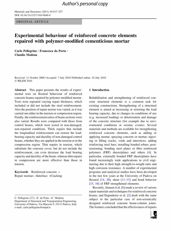
Among these six specimens, two beams (T50t, one
for each beam type) were repaired with mortar having
50 mm thickness in the tension region and other two
beams (T50c, one for each beam type) were repaired
with mortar having 50 mm thickness in the compres-
sion region (in this cases repair included steel
reinforcement). Repair mortar having 20 mm thick-
ness was applied in the tension region (T20t_a, with
three reinforcing bars in tension) and mortar having
30 mm thickness was applied in the compression
region (T30c_b, with two reinforcing bars in tension)
on the two remaining beams since the concrete cover
of the longitudinal reinforcement was slightly differ-
ent at the two beam sides. In these two cases repair
substitutes only the concrete cover and, in the latter
case, it partially includes the transversal reinforce-
ment, but not the longitudinal one. Hence the bond
surface has similar characteristics in both cases with
the only difference consisting in the partial inclusion
of the extreme part of the stirrups at the compressive
side. Figure 1 shows the details and Table 1 lists the
data of the tested beams.
2.2 Materials
The main mechanical properties of concrete were
experimentally evaluated after 28 days curing. Mean
cubic compressive strength, measured on four sam-
ples cast during specimen construction and with
dimension 150 9 150 9 150 mm, was 34.8 N/mm2.
Cylinder compressive strength, measured on samples
with diameter of 150 mm and height of 320 mm, was
33.6 N/mm2. Mean tensile strength, measured with
splitting tests on three cylindrical samples of the
same dimensions, was 3.2 N/mm2. Elastic modulus
was not measured, but according to the measured
cylinder compressive strength and Eurocode 2
Materials and Structures (2011) 44:517–527 519
Author's personal copy
formulation [3], it was assumed to be around
32,500 N/mm2.
Ribbed bars used for longitudinal reinforcement
(diameter 12 mm) and for transversal reinforcement
(diameter 8 mm) were both tested in tension.
Mechanical properties were similar for the two types
of bars, with mean yield stress of 532 N/mm2 and
mean tensile strength of 628 N/mm2.
Finally, the cementicious material, used for repair-
ing all beams, was premixed, tixotropic, polymer-
modified mortar with high-strength hydraulic binders
and aggregates with maximum thickness of 4 mm.
This product has high bond properties, low CO2 and
vapour permeability, limited shrinkage. It is generally
used for cover repair in reinforced concrete structures.
Mechanical properties of the repair mortar were
measured on samples with dimensions of 40 9
40 9 160 mm, cast during the repair interventions.
These samples were tested after 28 days curing.
Density of hardened mortar was 2,170 kg/m3. Mean
tensile strength deducted from flexural tests was equal
to 3.5 N/mm2. Mean cubic compressive strength was
39.6 N/mm2, mean elastic modulus was 26240 N/mm2.
Table 2 compares the mechanical properties of the
concrete support and the repair material. It can be seen
that the measured mechanical properties differ for no
more than 10%, and concrete and mortar elastic
modules differ for less than 10 kN/mm2.
2.3 Testing procedures
Flexural tests on beams were carried out under
typical four-point testing configuration (Fig. 1). The
2 φ 12
3 φ 12
T0_a
270 1600 150
P
150
665 270 665
310
150
310
2 φ 12
3 φ 12
T0_b
2 φ 12
3 φ 12
T50t_b
2 φ 12
3 φ 12
T50t_a
50
50
2 φ 12
3 φ 12
T20t_a
20
2 φ 12
3 φ 12
T30c_b30
2 φ 12
3 φ 12
T50c_a
2 φ 12
3 φ 12
T50c_b
50
50
Fig. 1 Dimensions, rebars and repairs arrangement of beams
Table 1 Details of specimens
Type of
element/test
Section
(mm2)
Longitudinal reinforcement ql (%) Transversal
reinforcement
qw (%) Condition Designation
Tension Compression
Beam flexural 150 9 310 3U12 2U12 0.73 1U8/200 mm 0.33 Control beam T0_a
Repair 50 mm ten. T50t_a
Repair 50 mm co. T50c_a
Repair 20 mm ten. T20t_a
2U12 3U12 0.49 1U8/200 mm 0.33 Control beam T0_b
Repair 50 mm ten. T50t_b
Repair 50 mm co. T50c_b
Repair 30 mm co. T30c_b
520 Materials and Structures (2011) 44:517–527
Author's personal copy
shear span was 665 mm (ratio between shear span
and effective depth of the cross section equal to about
2.5). Tests were carried out monotonically, with loads
increased between 0.1 and 0.5 kN/s. Load cell with
300 kN capacity was used to measure applied loads.
Control beams were instrumented with five strain
transducers (DD1; 100 mm measuring base), close to
beam midspan. Three DD1 were placed sequentially
on the lateral face of the beam, in the tension region,
along the longitudinal reinforcement, to measure
opening and propagation of cracks. One DD1 was
placed on the beam intrados, in the tension region;
the other was placed on the beam extrados, in the
compression region. Three linear variable differential
transducers (LVDT) were placed at the beam extra-
dos at supports and at the beam intrados at midspan to
measure displacements and deflections. For the
repaired beams, other three strain transducers (DD1)
were placed on the lateral face of the beam along the
mortar repair layer, and across the repair layer–
concrete beam interface, to gather information on the
behaviour of the strengthening material, and the
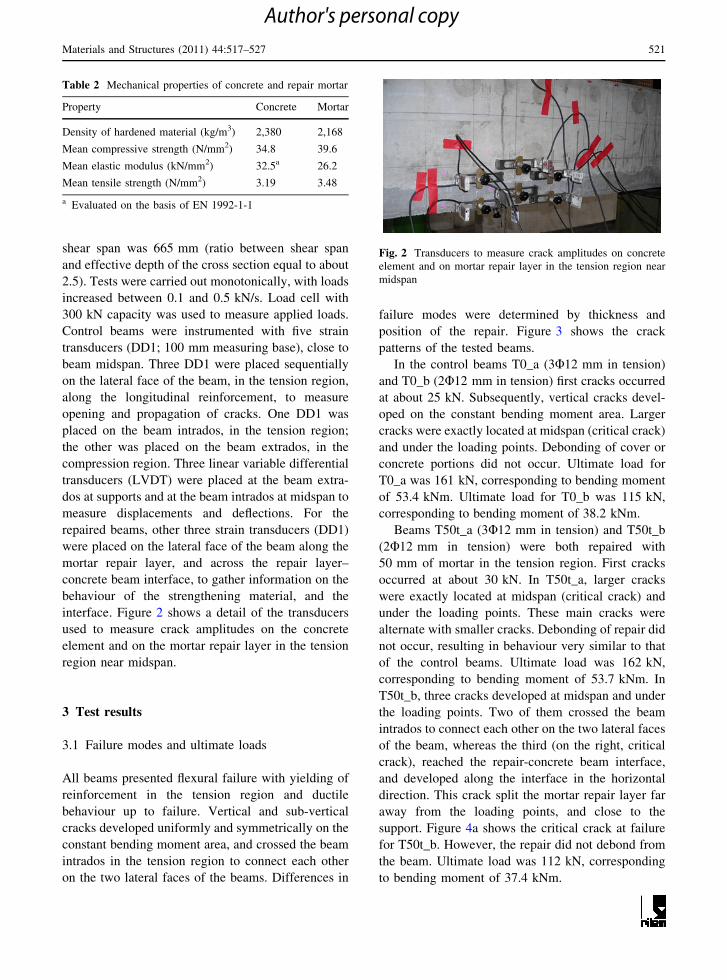
interface. Figure 2 shows a detail of the transducers
used to measure crack amplitudes on the concrete
element and on the mortar repair layer in the tension
region near midspan.
3 Test results
3.1 Failure modes and ultimate loads
All beams presented flexural failure with yielding of
reinforcement in the tension region and ductile
behaviour up to failure. Vertical and sub-vertical
cracks developed uniformly and symmetrically on the
constant bending moment area, and crossed the beam
intrados in the tension region to connect each other
on the two lateral faces of the beams. Differences in
failure modes were determined by thickness and
position of the repair. Figure 3 shows the crack
patterns of the tested beams.
In the control beams T0_a (3U12 mm in tension)
and T0_b (2U12 mm in tension) first cracks occurred
at about 25 kN. Subsequently, vertical cracks devel-
oped on the constant bending moment area. Larger
cracks were exactly located at midspan (critical crack)
and under the loading points. Debonding of cover or
concrete portions did not occur. Ultimate load for
T0_a was 161 kN, corresponding to bending moment
of 53.4 kNm. Ultimate load for T0_b was 115 kN,
corresponding to bending moment of 38.2 kNm.
Beams T50t_a (3U12 mm in tension) and T50t_b
(2U12 mm in tension) were both repaired with
50 mm of mortar in the tension region. First cracks
occurred at about 30 kN. In T50t_a, larger cracks
were exactly located at midspan (critical crack) and
under the loading points. These main cracks were
alternate with smaller cracks. Debonding of repair did
not occur, resulting in behaviour very similar to that
of the control beams. Ultimate load was 162 kN,
corresponding to bending moment of 53.7 kNm. In
T50t_b, three cracks developed at midspan and under
the loading points. Two of them crossed the beam
intrados to connect each other on the two lateral faces
of the beam, whereas the third (on the right, critical
crack), reached the repair-concrete beam interface,
and developed along the interface in the horizontal
direction. This crack split the mortar repair layer far
away from the loading points, and close to the
support. Figure 4a shows the critical crack at failure
for T50t_b. However, the repair did not debond from
the beam. Ultimate load was 112 kN, corresponding
to bending moment of 37.4 kNm.
Table 2 Mechanical properties of concrete and repair mortar
Property Concrete Mortar
Density of hardened material (kg/m3) 2,380 2,168
Mean compressive strength (N/mm2) 34.8 39.6
Mean elastic modulus (kN/mm2) 32.5a 26.2
Mean tensile strength (N/mm2) 3.19 3.48
a Evaluated on the basis of EN 1992-1-1
Fig. 2 Transducers to measure crack amplitudes on concrete
element and on mortar repair layer in the tension region near
midspan
Materials and Structures (2011) 44:517–527 521
Author's personal copy
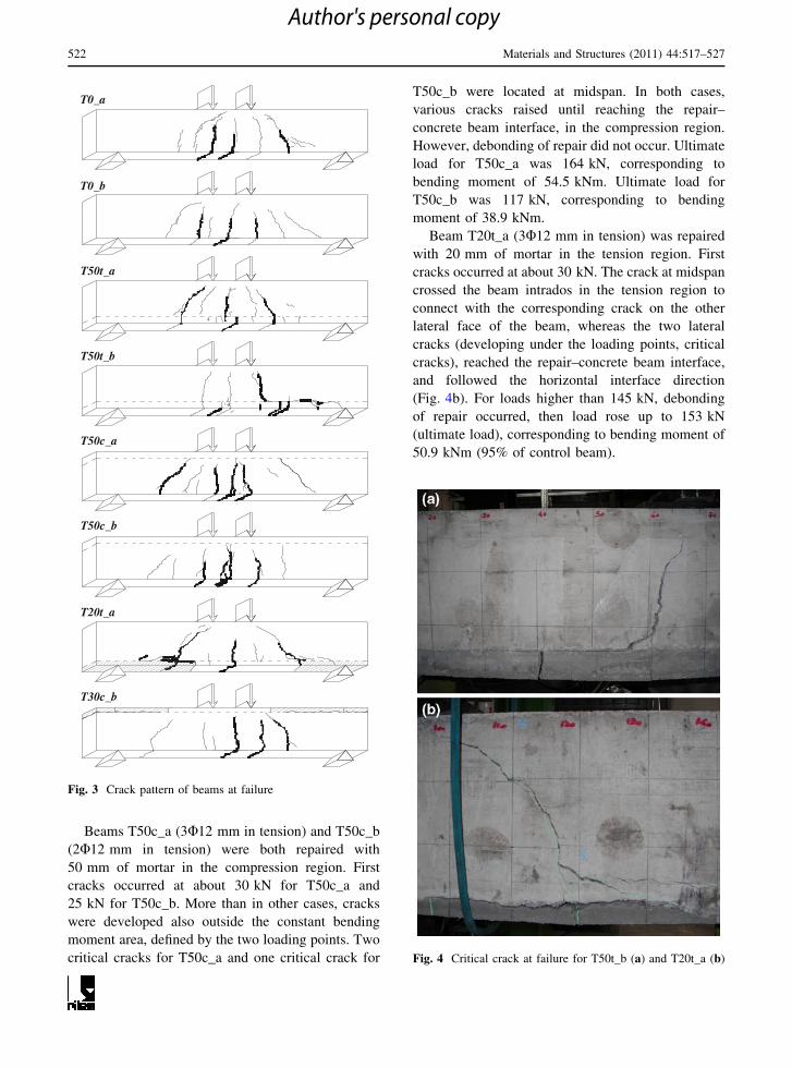
Beams T50c_a (3U12 mm in tension) and T50c_b
(2U12 mm in tension) were both repaired with
50 mm of mortar in the compression region. First
cracks occurred at about 30 kN for T50c_a and
25 kN for T50c_b. More than in other cases, cracks
were developed also outside the constant bending
moment area, defined by the two loading points. Two
critical cracks for T50c_a and one critical crack for
T50c_b were located at midspan. In both cases,
various cracks raised until reaching the repair–
concrete beam interface, in the compression region.
However, debonding of repair did not occur. Ultimate
load for T50c_a was 164 kN, corresponding to
bending moment of 54.5 kNm. Ultimate load for
T50c_b was 117 kN, corresponding to bending
moment of 38.9 kNm.
Beam T20t_a (3U12 mm in tension) was repaired
with 20 mm of mortar in the tension region. First
cracks occurred at about 30 kN. The crack at midspan
crossed the beam intrados in the tension region to
connect with the corresponding crack on the other
lateral face of the beam, whereas the two lateral
cracks (developing under the loading points, critical
cracks), reached the repair–concrete beam interface,
and followed the horizontal interface direction
(Fig. 4b). For loads higher than 145 kN, debonding
of repair occurred, then load rose up to 153 kN
(ultimate load), corresponding to bending moment of
50.9 kNm (95% of control beam).
T0_a
T0_b
T20t_a
T50t_b
T50t_a
T30c_b
T50c_a
T50c_b
Fig. 3 Crack pattern of beams at failure
Fig. 4 Critical crack at failure for T50t_b (a) and T20t_a (b)
522 Materials and Structures (2011) 44:517–527
Author's personal copy

Finally, beam T30c_a (2U12 mm in tension) was
repaired with 30 mm of mortar in the compression
region. First cracks occurred at about 25 kN. Critical
crack was located at midspan, but cracks were
developing also outside the constant bending moment
area. For loads higher than 110 kN, debonding of
repair occurred, with horizontal cracks propagating
along the repair-concrete beam interface at the beam
ends (see Fig. 5). Load then rose up to 112 kN
(ultimate load, 97% of control beam), corresponding
to bending moment of 37.3 kNm.
3.2 Loads and deflections
Figure 6 shows the load deflection curves of A-type
(above) and B-type (below) beams. Figure 7 shows
the load strain curves of beams repaired in tension
(T50t_a) and in compression (T50t_c) with thick
repair layer, and beams repaired in tension (T20t_a)
and in compression (T30t_c) with thin repair layer.
The diagrams show strains measured over the beam
extrados, under the beam intrados, and on the beam
lateral sides close to the intrados. In addition, for
beams repaired in tension, the diagrams give strains
measured on the lateral side of the repair. In these
diagrams, extrados strains (compression) are plotted
positive as side and intrados strains (tension).
In A-type beams (3U12 mm in tension), the
control beam (T0_a) and the beam repaired in
compression (T50c_a) had the same elastic stiffness
before cracking, two times higher than initial stiffness
of beams repaired in tension region (T50t_a and
T20t_a). In the control beam, cracking occurred at
23.4 kN, that is 78% of the evaluated theoretical
value (30 kN). In the repaired beams, cracking
occurred around 33 kN, that is 10% higher than the
theoretical value and 41% higher than the actual
value of the control beam (see Table 3). This is due
to the higher strength of the repair mortar (see
Table 2).
According to the initial stiffness, the midspan
deflection at cracking of beams repaired in tension
(T50t_a and T20t_a, 0.85 mm on average) was about
two times higher than that of the beam repaired in
compression (T50c_a, 0.38 mm; see Table 4). This
value was lower in the control beam, as cracking
occurred earlier than in repaired beams (T0_a,
0.21 mm). After cracking, differences in stiffness
decreased.
Yielding was evaluated to occur after completion
of the cracking phase, on the basis of strains measured
by instruments placed on the beam intrados and lateral
faces. Reinforcement yielding is also shown by the
bent of load deflection curves in Fig. 6. Yield loads in
the control beam (T0_a, 144 kN) and the beamFig. 5 Debonding of mortar repair layer for T30c_a
Load-deflection, A-type beams
0
30
60
90
120
150
180
Deflection [mm]
Lo
ad [
kN]
T0_aT50t_aT50c_aT20t_a
Load-deflection, B-type beams
0
20
40
60
80
100
120
0 3 6 9 12 15 18
0 2 4 6 8 10 12
Deflection [mm]
Lo
ad [
kN]
T0_bT50t_bT50c_bT30c_b
Fig. 6 Load deflection curves of A-type and B-type beams
Materials and Structures (2011) 44:517–527 523
Author's personal copy

repaired in compression (T50c_a, 153 kN) were
higher than the theoretical value evaluated for the
control beam (138 kN) and higher than the experi-
mental values measured on the other beams (T50t_a
and T20t_a, 139 kN on average; see Table 3). The
corresponding values of midspan deflection were
similar in all beams (on average, 7.28 mm) except for
the beam repaired in tension by substituting only the
cover (T20t_a). In this case, deflection at yielding was
8.95 mm.
Ultimate load was measured in all beams, but in
two beams (T50c_a and T0_b), LVDTs measuring
midspan deflection were not working until the end of
the test. All A-type beams practically reached or
Load-strain, T50t_a
0
30
60
90
120
150
180
Strain [10-3]
Lo
ad [
kN]
extrados strain
beam strainrepair strain
intrados strain
Load-strain, T50c_a
0
30
60
90
120
150
180
Strain [10-3]
Lo
ad [
kN]
extrados strain
beam strain
intrados strain
Load-strain, T20t_a
0
30
60
90
120
150
180
0 2 4 6 8 10
0 2 4 6 8 10
Strain [10-3]
Lo
ad [
kN]
extrados strainbeam strainrepair strainintrados strain
Load-strain, T30c_b
0
30
60
90
120
0 2 4 6 8 10
0 2 4 6 8 10
Strain [10-3]
Loa
d [k
N]
extrados strain
beam strain
intrados strain
Fig. 7 Load strain curves of beams repaired in tension (T50t_a; T20t_a), and in compression (T50c_a, T30c_b)
Table 3 Results of flexural tests
Beam Cracking load (kN) (a)/(b) Yield load (kN) (a)/(b) Ultimate load (kN) (a)/(b)
Theory (a) Test (b) Theory (a) Test (b) Theory (a) Test (b)
T0_a 30.0 23.4 1.28 138 144 0.96 162 161 1.01
T50t_a – 32.9 0.91 – 140 0.99 – 162 1.00
T50c_a – 32.4 0.93 – 153 0.90 – 164 0.99
T20t_a – 33.8 0.89 – 138 1.00 – 153 1.06
T0_b 29.4 27.4 1.07 93 93 1.00 109 115 0.95
T50t_b – 31.1 0.95 – 93 1.00 – 112 0.97
T50c_b – 24.7 1.19 – 96 0.97 – 115 0.95
T30c_b – 25.4 1.16 – 93 1.00 – 112 0.97
524 Materials and Structures (2011) 44:517–527
Author's personal copy
overcame the theoretical value of the ultimate load
evaluated for the control beam (162 kN), except for
the beam repaired in tension by substituting only the
cover (T20t_a, ultimate load of 153 kN, that is 94%
of the theoretical value). In the case of thick repairs,
performance of repaired beams (T50t_a, 162 kN;
T50c_a, 164 kN) were even better than that of the
control beam (T0_a, 161 kN; see Table 3).
At ultimate load, deflections reached about 15 mm
in the control beam (T0_a, 15.09 mm), and the beam
repaired in tension (T50t_a, 14.87 mm). Even if it
was not possible to have this measure for the beam
repaired in compression (T50c_a), it is very likely
that its midspan deflection was in the same range, as
the experimentally observed behaviour was very
similar. Instead, the beam repaired in tension by
substituting only the cover (T20t_a) showed lower
midspan deflection at ultimate load (11.49 mm, see
Table 4). Therefore, if beam behaviour is evaluated
by means of ductility index, that is the ratio of
deflection at ultimate load to yielding, the beam
repaired with thick mortar layer in tension (T50t_a)
had ductility index of 2.03, very similar to the
ductility index of the control beam (T0_a, 2.00). The
beam repaired in compression also had similar
behaviour. Instead, the beam repaired in tension
by substituting only the cover (T20t_a) showed
worse behaviour, with ductility index of only 1.28
(see Table 4).
In B-type beams (2U12 mm in tension), all beams
had similar elastic stiffness before cracking. In the
control beam (T0_b), cracking occurred at 27.4 kN,
that is 93% of the evaluated theoretical value
(29.4 kN). Similar values were reached by beams
repaired in compression (T50c_b, 24.7 kN, and
T30c_b, 25.4 kN). In the beam repaired in tension
(T50t_b), cracking occurred at 31.1 kN, that is 6%
higher than the theoretical value and 14% higher than
actual value of control beam (see Table 3). This
increase is due to the higher tensile strength of the
repair mortar. According to the initial stiffness,
midspan deflection at cracking in all beams was in
the range between 0.36 and 0.40 mm. After cracking,
the two beams repaired in compression (T50c_b and
T30c_b) presented the same stiffness as the control
beam (T0_b), whereas the beam repaired in tension
(T50t_b) had the lowest stiffness and the highest
deflections.
Yield loads, in all beams, almost reached the
theoretical value evaluated for the control beam
(93 kN) except for the beam repaired in compression
(T50c_b), in which yield load was slightly higher
(96 kN, see Table 3). The corresponding values
of midspan deflection were similar in all beams
(on average, 4.5 mm). The beam repaired in com-
pression by substituting only the cover (T30c_b) had
the lowest deflection, 4.32 mm; the beam repaired in
tension (T50t_b) had the highest deflection, 4.81 mm
(see Table 4).
All type-B beams overcame the theoretical value
of ultimate load evaluated for the control beam
(109 kN). The control beam and the beam repaired in
compression (T0_b and T50c_b) reached 115 kN
(that is 105% of the theoretical value), whereas the
beam repaired in tension and that repaired in
compression by substituting only the cover (T50t_b
and T30c_b) reached 112 kN (103% of the theoret-
ical value; see Table 3).
Table 4 Deflections and ductility index of flexural tests
Beam Cracking load Yield load Ultimate load Ductility
index (-)Load (kN) Defl. (mm) Load (kN) Defl. (mm) Load (kN) Defl. (mm)
T0_a 23.4 0.21 144 7.54 161 15.09 2.00
T50t_a 32.9 0.81 140 7.34 162 14.87 2.03
T50c_a 32.4 0.38 153 6.96 164 (8.95)a –
T20t_a 33.8 0.90 138 8.95 153 11.49 1.28
T0_b 27.4 0.37 93 4.45 115 (7.73)a –
T50t_b 31.1 0.36 93 4.81 112 10.13 2.11
T50c_b 24.7 0.39 96 4.67 115 10.94 2.34
T30c_b 25.4 0.40 93 4.32 112 10.06 2.33
a Last value measured before LVDT removal
Materials and Structures (2011) 44:517–527 525
Author's personal copy

At ultimate load, deflections were all around
10 mm. The beam repaired in compression with thick
mortar layer (T50c_b) gave the highest value
(10.94 mm); the beam repaired in compression with
thin mortar layer (T30c_b) gave the lowest value
(10.06 mm), followed by the beam repaired in tension
(T50t_b, 10.13 mm). Even if it was not possible to
have this measure in the control beam (T0_b), it is
very likely that its midspan deflection was in the same
range, as the experimentally observed behaviour was
very similar. Taking into account the ductility index, it
can be seen that the two beams repaired in compres-
sion (T50c_b and T30c_b) had almost the same value
(2.33), whereas the beam repaired in tension (T50t_b)
had slightly lower ductility (2.11, see Table 4), due to
the lower stiffness shown in cracked phase and the
higher deflection at yielding.
Finally, strain measurements confirmed that beam
substrate and repair layer, in beams repaired with
thick mortar layer in tension (see T50t_a in Fig. 7),
were working together, i.e. collaboration between
the two materials occurred with negligible sliding.
Figure 7 shows that strains measured on close posi-
tions on the lateral faces of beam and repair, and at
beam intrados (thus on repair), had similar trends and
were consistent with position of instruments and
distance from neutral axis. The same can be also said
for beams repaired with mortar in compression (see
T50c_a and T30c_b in Fig. 7). The strains measured
on the beam extrados (thus on repair), were consistent
with the beam behaviour and were very similar to
those measured on the beams non-repaired at the
extrados (compare, for example, T50c_a and T50t_a).
Instead, in the beams repaired with thin mortar layer
in tension (see T20t_a in Fig. 7), the strains measured
on the repair were almost zeroed.
4 Discussion
Mortar repair in the tension region of beams could
increase the value of loads that induce the first crack
from about 14 to 44%, although the tensile strength of
the repair mortar was only 10% higher than the tensile
strength of concrete. The position of the repair had
greater influence on the beam behaviour in the case of
beams with higher percentage of reinforcement in
tension. In any case, the repairs in compression
increased the beam stiffness or re-established the same
stiffness of the non-damaged control beams, whereas
the repairs in tension always decreased the stiffness.
In the case of thick repairs (50 mm) including
longitudinal reinforcement, applied on the compres-
sion or tension region of beams, experimental results
showed that the repair technique and material could
re-establish the load bearing capacity of the non-
damaged control beams, evaluated by experimental
testing and theoretical calculation. Even though some
cracks opened along the repair–concrete beam inter-
face, sliding of the two materials did not occur and
the original reinforced concrete beam and the repair
material kept working together. The crack patterns
and the strain measurements demonstrated this fact.
In the case of thin repairs, substituting only the
concrete cover, debonding of the repair occurred and
caused the beam failure. For thin repair (20 mm) in
tension, collapse was anticipated at 94% of the
control beam experimental and theoretical ultimate
loads, for thin repair (30 mm) in compression, this
effect was less marked. In the latter case, ultimate
load was 97% that of the control beam and 103% of
the theoretical value. In addition, strain analysis of
thin repair in tension showed that the repair was not
collaborating to the load bearing capacity, whereas
thin repair in compression was loaded.
Analysis of the ductility index confirmed these
results. Even though displacements at ultimate load
were not measured for two beams, it was possible
to conclude that thick repair, in general, could
re-establish the available ductility of the non-damaged
control beams, that is, to ensure the same beam
deflection capacity after repair. Thin repair in com-
pression had the same effect, whereas thin repair in
tension decreased the available ductility to only 64%
that of the control beam.
5 Conclusions
In this work an experimental investigation to control
the effectiveness of polymer-modified cementicious
mortar repairs applied to beams under flexural loads
is carried out. The aim is to give some new insights
on validating the effectiveness of such materials
in recovering the properties of non-damaged, non-
repaired beams, verifying the effect of (a) the repair
position (tension or compression region), (b) the
percentage of reinforcement in the repaired region,
526 Materials and Structures (2011) 44:517–527
Author's personal copy
and (c) the repair thickness (including the steel
reinforcement or not), on cracking pattern and, in
general, structural behaviour of flexural element.
The main conclusions arising from the experimental
tests show that polymer-modified cementicious mor-
tars, with mechanical properties like those obtained in
the present experimental investigation and similar to
those of the concrete substrate (compressive strengths
differing less than 10%, and elastic modules differing
less than 10 kN/mm2), can be effective for the repair of
beams. The effectiveness of the intervention depends
also on the position and thickness of the repair layer in
relation to the position of the steel reinforcement.
In repaired beams, first cracking occurs later than
in control beams. Thick repairs that include the lon-
gitudinal reinforcement can restore the load-bearing
capacity and ductility of non-damaged control beams,
whether they are applied in the tension or in the
compression region. Thin repairs in tension, which
substitute the concrete cover, but do not include the
reinforcement, can even decrease the load bearing
capacity and ductility of the beam. Thin repairs in
compression are more effective than those in tension.
It must be observed that this study uses a polymer-
modified repair material for the rehabilitation of a non
damaged member built in laboratory conditions. The
specimens have been built in conditions as close as
possible to field members which are typically repaired
by chipping away bad concrete, sandblasting rebar, and
then filling the void with repair material. Therefore, even
if the interface of the specimens has been roughened
similarly to field conditions, bond, stress distribution,
and fracture of the repair material could be slightly
different in field situations with respect to that obtained
for the specimens of this study in laboratory conditions.
Acknowledgements The authors gratefully acknowledge
Tassullo S.p.A. that provided materials and specimens for
experimental testing, and Eng. Fabio Mazzucco for his
contribution to the experimental investigation developed
during his MSc thesis. The experimental tests were carried out
at the Laboratory of Structural Materials Testing of the
University of Padova, Italy.
References
1. Emberson NK, Mays GC (1996) Significance of property
mismatch in the patch repair of structural concrete. Part 3:
reinforced concrete members in flexure. Mag Concr Res
48(174):45–57
2. Engindeniz M, Kahn LF, Zureick AH (2005) Repair and
strengthening of reinforced concrete beam-column joints:
state of the art. ACI Struct J 102:187–197
3. European Committee for Standardization (2004) Eurocode
2—design of concrete structures. Part 1–1: General rules
and rules for buildings. EN 1992-1-1, Brussels, Belgium
4. European Committee for Standardization (2005) Products
and systems for the protection and repair of concrete
structures—definitions, requirements, quality control and
evaluation of conformity. Part 3: structural and non-
structural repair. EN 1504-3, Brussels, Belgium
5. Hassan KE, Brooks JJ, Al-Alawi L (2001) Compatibility of
repair mortars with concrete in a hot-dry environment.
Cem Concr Compos 23:93–101
6. Jumaat MZ, Kabir MH, Obaydullah M (2006) A review of
the repair of reinforced concrete beams. J Appl Sci Res
2(6):317–326
7. Kim JHJ, Lim YM, Won JP, Park HG, Lee KM (2007)
Shear capacity and failure behaviour of DFRCC repaired
RC beams at tensile region. Eng Struct 29:121–131. doi:
10.1016/j.engstruct.2006.04.023
8. Mangat PS, O’Flaherty FJ (2000) Influence of elastic
modulus on stress redistribution and cracking in repair
patches. Cem Concr Res 30:125–136
9. Nounu G, Chaudhary Z-UL-H (1999) Reinforced concrete
repair in beams. Constr Build Mater 13:195–212
10. Park SK, Yang DS (2005) Flexural behaviour of reinforced
concrete beams with cementitious repair materials. Mater
Struct 38:329–334
11. Pellegrino C, Modena C (2002) FRP shear strengthening of
RC beams with transverse steel reinforcement. J Compos
Constr 6(2):104–111
12. Pellegrino C, Modena C (2006) FRP shear strengthening of
RC beams: experimental study and analytical modelling.
ACI Struct J 103(5):720–728
13. Pellegrino C, Modena C (2008) An experimentally based
analytical model for shear capacity of FRP strengthened rein-
forced concrete beams. Mech Compos Mater 44(3):231–244
14. Pellegrino C, Modena C (2009) Flexural strengthening of
real-scale RC and PRC beams with end-anchored pre-
tensioned FRP laminates. ACI Struct J 106(3):319–328
15. Pellegrino C, Modena C (2009) Influence of FRP axial
rigidity on FRP-concrete bond behaviour: an analytical
study. Adv Struct Eng 12(5):639–649
16. Pellegrino C, Tinazzi D, Modena C (2008) An experi-
mental study on bond behavior between concrete and FRP
reinforcement. J Compos Constr 12(2):180–189
17. Pellegrino C, da Porto F, Modena C (2009) Rehabilitation
of reinforced concrete axially loaded elements with poly-
mer-modified cementicious mortar. Constr Build Mater
23(10):3129–3137
18. Rı́o O, Andrade C, Izquierdo D, Alonso C (2005) Behaviour
of patch-repaired concrete structural elements under increas-
ing static loads to flexural failure. J Mater Civ Eng 17(2):
168–177. doi:10.1061/(ASCE)0899-1561(2005)17:2(168)
19. Shannag MJ, Al-Ateek SA (2006) Flexural behaviour of
strengthened concrete beams with corroding reinforce-
ment. Constr Build Mater 20:834–840
20. Valluzzi MR, Grinzato E, Pellegrino C, Modena C (2008)
IR thermography for interface analysis of FRP laminates
externally bonded to RC beams. Mater Struct 42(1):25–34
Materials and Structures (2011) 44:517–527 527
Author's personal copy
Related Documents