International Journal of Innovative Technology and Exploring Engineering (IJITEE) ISSN: 2278-3075 (Online), Volume-10 Issue-1, November 2020 309 Published By: Blue Eyes Intelligence Engineering and Sciences Publication Retrieval Number: 100.1/ijitee.L78751091220 DOI: 10.35940/ijitee.L7875.1110120 Journal Website: www.ijitee.org Abstract: Paper Compared to traditional cast-in-place concrete structures, the precast Concrete structures are usually constructed in a controlled environment , i.e. plants, and then assembled through certain links at the construction site. The concrete precast concrete structures can therefore have better concrete quality and help to reduce labor costs and increase construction speed. Because of these advantages, in recent years the precast concrete structures have received much attention. This research work therefore presents a reasonable procedure for designing a grouted sleeve splice connection using a simple material such as standard pipes with little workmanship which gives the design a good advantage compared to just using selection tables for expensive proprietary similar connection. Such splices' mechanical behavior is a function of two essential mechanisms: bar-to-grout bond behavior, and sleeve-to-grout bond behavior. To achieve the purpose of this analysis work , three arrangements were manufactured and checked under incremental axial tensile load with an all-out number of 66 grouted splice sleeve specimens. While experimental methods of investigation are extremely useful in obtaining information about the grouted splice sleeve connection behavior, the use of numerical models helps to develop good comprehension of behavior at lower cost. Models of non-linear finite-element analysis for grouted splice sleeve connection were presented in this research. The research utilized the commercial Finite Element modeling software (ANSYS) to study the effects of some parameters that are important in the bond behavior of the grouted splice sleeve connection and compare the analytical results with the experimental results to confirm the analytical model. The average efficiency of the finite element models using ANSYS was 92.5%. Having the finite element model validated, a parametric study was performed using ANSYS to evaluate the effect of the following parameters on the behavior of grouted splice sleeve: bar diameter, embedded length, grout compressive strength, sleeve wall thickness, and sleeve inner diameter. Keywords : Precast concrete; connection; Grouted; splice; Mechanical Splice; Confinement; Bond Behavior; Finite Element; bar embedment length; Material nonlinearity. I. INTRODUCTION Precast concrete buildings have gained popularity around the world, see Fig. 1. Revised Manuscript Received on November 30, 2020. * Correspondence Author Abdallh M. Soliman *, lecturer Assistant, October High Institute, OHI, Giza, Egypt. Email: [email protected] Hatem H. Ibrahim, Assistant Professor, Cairo University, Giza, Egypt. Email: [email protected] Hossma A. Hodhod, professor, Cairo University, Giza, Egypt. Email: [email protected] © The Authors. Published by Blue Eyes Intelligence Engineering and Sciences Publication (BEIESP). This is an open access article under the CC BY-NC-ND license (http://creativecommons.org/licenses/by-nc-nd/4.0/ ) Buildings which were already constructed with cast-in-situ concrete can be constructed with precast concrete components prefabricated within the factories. These ready-made loose components such as precast concrete wall panels are introduced on site. Too, the association can extend the structural integrity of precast concrete components. A grouted splice could be a type of mechanical connectors that utilized as the connections for precast concrete structures. Figure 2 appears a few common applications of mechanical splices in precast concrete structures, where they can be utilized as the column-to-base, wall – to - wall, column – to - column, beam-to-beam connections. Splice connectors are cast along with precast components some time recently transported to the construction sites. In order to assemble the precast elements, the steel bars projecting from them are inserted and grouted within the connectors embedded within the other components. The preferences of splice connectors include ease of installations that speed up the construction pace, way better bond efficiency under proper confinement that leads to shorter required bar development length and others. Fig. 1 : Precast Concrete Building Fig.2 : Application of mechanical Splice. Experimental and Analytical Study of Grouted Sleeve Splice Under Axial Tensile Load Abdallh M. Soliman, Hatem H. Ibrahim, Hossam A. Hodhod

Welcome message from author
This document is posted to help you gain knowledge. Please leave a comment to let me know what you think about it! Share it to your friends and learn new things together.
Transcript
International Journal of Innovative Technology and Exploring Engineering (IJITEE) ISSN: 2278-3075 (Online), Volume-10 Issue-1, November 2020
309
Published By: Blue Eyes Intelligence Engineering and Sciences Publication
Retrieval Number: 100.1/ijitee.L78751091220 DOI: 10.35940/ijitee.L7875.1110120 Journal Website: www.ijitee.org
Abstract: Paper Compared to traditional cast-in-place concrete structures, the precast Concrete structures are usually constructed in a controlled environment , i.e. plants, and then assembled through certain links at the construction site. The concrete precast concrete structures can therefore have better concrete quality and help to reduce labor costs and increase construction speed. Because of these advantages, in recent years the precast concrete structures have received much attention. This research work therefore presents a reasonable procedure for designing a grouted sleeve splice connection using a simple material such as standard pipes with little workmanship which gives the design a good advantage compared to just using selection tables for expensive proprietary similar connection. Such splices' mechanical behavior is a function of two essential mechanisms: bar-to-grout bond behavior, and sleeve-to-grout bond behavior. To achieve the purpose of this analysis work , three arrangements were manufactured and checked under incremental axial tensile load with an all-out number of 66 grouted splice sleeve specimens. While experimental methods of investigation are extremely useful in obtaining information about the grouted splice sleeve connection behavior, the use of numerical models helps to develop good comprehension of behavior at lower cost. Models of non-linear finite-element analysis for grouted splice sleeve connection were presented in this research. The research utilized the commercial Finite Element modeling software (ANSYS) to study the effects of some parameters that are important in the bond behavior of the grouted splice sleeve connection and compare the analytical results with the experimental results to confirm the analytical model. The average efficiency of the finite element models using ANSYS was 92.5%. Having the finite element model validated, a parametric study was performed using ANSYS to evaluate the effect of the following parameters on the behavior of grouted splice sleeve: bar diameter, embedded length, grout compressive strength, sleeve wall thickness, and sleeve inner diameter.
Keywords : Precast concrete; connection; Grouted; splice;
Mechanical Splice; Confinement; Bond Behavior; Finite Element; bar embedment length; Material nonlinearity.
I. INTRODUCTION
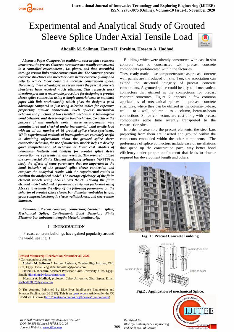
Precast concrete buildings have gained popularity around the world, see Fig. 1.
Revised Manuscript Received on November 30, 2020. * Correspondence Author
Abdallh M. Soliman *, lecturer Assistant, October High Institute, OHI, Giza, Egypt. Email: [email protected]
Hatem H. Ibrahim, Assistant Professor, Cairo University, Giza, Egypt. Email: [email protected]
Hossma A. Hodhod, professor, Cairo University, Giza, Egypt. Email: [email protected]
© The Authors. Published by Blue Eyes Intelligence Engineering and Sciences Publication (BEIESP). This is an open access article under the CC BY-NC-ND license (http://creativecommons.org/licenses/by-nc-nd/4.0/)
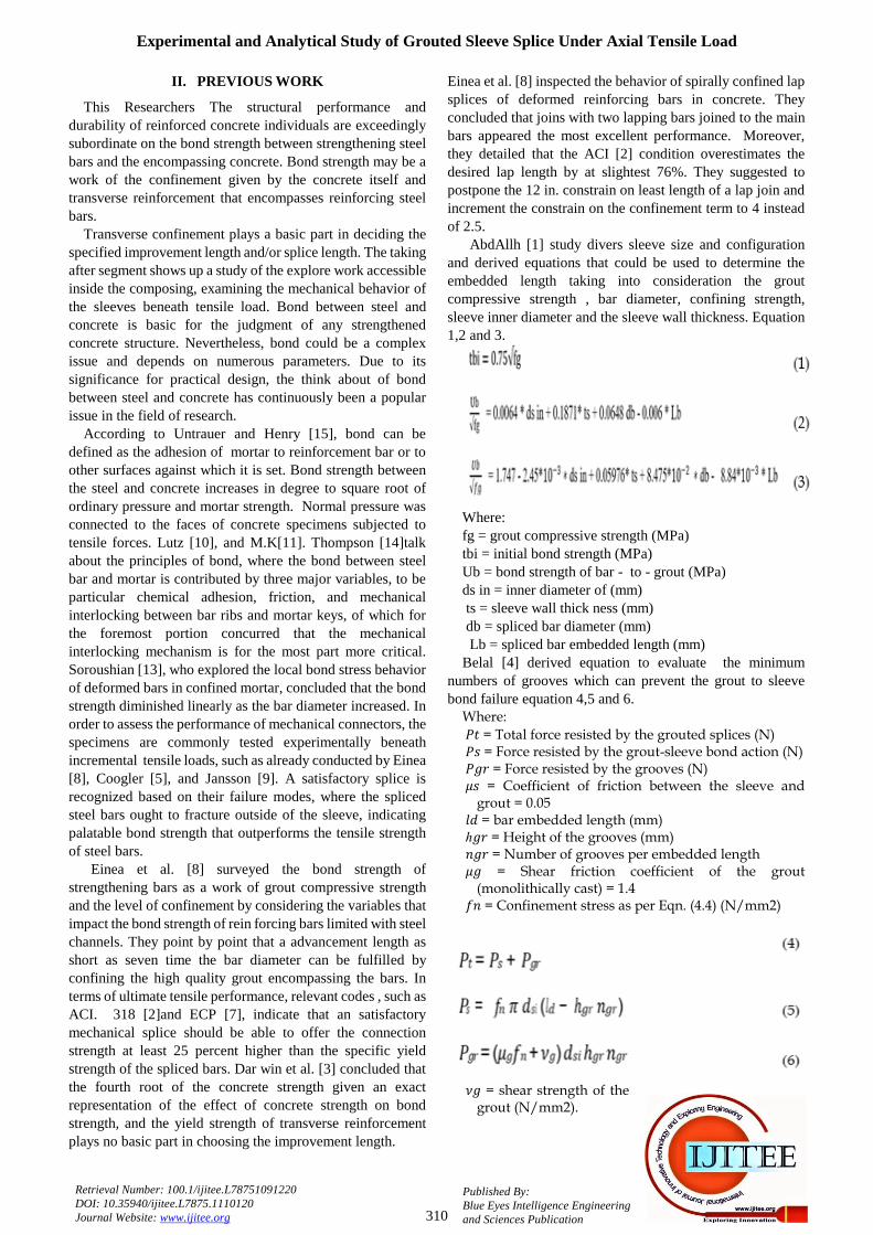
Buildings which were already constructed with cast-in-situ concrete can be constructed with precast concrete components prefabricated within the factories. These ready-made loose components such as precast concrete wall panels are introduced on site. Too, the association can extend the structural integrity of precast concrete components. A grouted splice could be a type of mechanical connectors that utilized as the connections for precast concrete structures. Figure 2 appears a few common applications of mechanical splices in precast concrete structures, where they can be utilized as the column-to-base, wall – to - wall, column – to - column, beam-to-beam connections. Splice connectors are cast along with precast components some time recently transported to the construction sites.
In order to assemble the precast elements, the steel bars projecting from them are inserted and grouted within the connectors embedded within the other components. The preferences of splice connectors include ease of installations that speed up the construction pace, way better bond efficiency under proper confinement that leads to shorter required bar development length and others.
Fig. 1 : Precast Concrete Building
Fig.2 : Application of mechanical Splice.
Experimental and Analytical Study of Grouted Sleeve Splice Under Axial Tensile Load
Abdallh M. Soliman, Hatem H. Ibrahim, Hossam A. Hodhod
Experimental and Analytical Study of Grouted Sleeve Splice Under Axial Tensile Load
310
Published By: Blue Eyes Intelligence Engineering and Sciences Publication
Retrieval Number: 100.1/ijitee.L78751091220 DOI: 10.35940/ijitee.L7875.1110120 Journal Website: www.ijitee.org
II. PREVIOUS WORK
This Researchers The structural performance and durability of reinforced concrete individuals are exceedingly subordinate on the bond strength between strengthening steel bars and the encompassing concrete. Bond strength may be a work of the confinement given by the concrete itself and transverse reinforcement that encompasses reinforcing steel bars.
Transverse confinement plays a basic part in deciding the specified improvement length and/or splice length. The taking after segment shows up a study of the explore work accessible inside the composing, examining the mechanical behavior of the sleeves beneath tensile load. Bond between steel and concrete is basic for the judgment of any strengthened concrete structure. Nevertheless, bond could be a complex issue and depends on numerous parameters. Due to its significance for practical design, the think about of bond between steel and concrete has continuously been a popular issue in the field of research.
According to Untrauer and Henry [15], bond can be defined as the adhesion of mortar to reinforcement bar or to other surfaces against which it is set. Bond strength between the steel and concrete increases in degree to square root of ordinary pressure and mortar strength. Normal pressure was connected to the faces of concrete specimens subjected to tensile forces. Lutz [10], and M.K[11]. Thompson [14]talk about the principles of bond, where the bond between steel bar and mortar is contributed by three major variables, to be particular chemical adhesion, friction, and mechanical interlocking between bar ribs and mortar keys, of which for the foremost portion concurred that the mechanical interlocking mechanism is for the most part more critical. Soroushian [13], who explored the local bond stress behavior of deformed bars in confined mortar, concluded that the bond strength diminished linearly as the bar diameter increased. In order to assess the performance of mechanical connectors, the specimens are commonly tested experimentally beneath incremental tensile loads, such as already conducted by Einea [8], Coogler [5], and Jansson [9]. A satisfactory splice is recognized based on their failure modes, where the spliced steel bars ought to fracture outside of the sleeve, indicating palatable bond strength that outperforms the tensile strength of steel bars.
Einea et al. [8] surveyed the bond strength of strengthening bars as a work of grout compressive strength and the level of confinement by considering the variables that impact the bond strength of rein forcing bars limited with steel channels. They point by point that a advancement length as short as seven time the bar diameter can be fulfilled by confining the high quality grout encompassing the bars. In terms of ultimate tensile performance, relevant codes , such as ACI. 318 [2]and ECP [7], indicate that an satisfactory mechanical splice should be able to offer the connection strength at least 25 percent higher than the specific yield strength of the spliced bars. Dar win et al. [3] concluded that the fourth root of the concrete strength given an exact representation of the effect of concrete strength on bond strength, and the yield strength of transverse reinforcement plays no basic part in choosing the improvement length.
Einea et al. [8] inspected the behavior of spirally confined lap splices of deformed reinforcing bars in concrete. They concluded that joins with two lapping bars joined to the main bars appeared the most excellent performance. Moreover, they detailed that the ACI [2] condition overestimates the desired lap length by at slightest 76%. They suggested to postpone the 12 in. constrain on least length of a lap join and increment the constrain on the confinement term to 4 instead of 2.5.
AbdAllh [1] study divers sleeve size and configuration and derived equations that could be used to determine the embedded length taking into consideration the grout compressive strength , bar diameter, confining strength, sleeve inner diameter and the sleeve wall thickness. Equation 1,2 and 3.
Where: fg = grout compressive strength (MPa) tbi = initial bond strength (MPa) Ub = bond strength of bar - to - grout (MPa) ds in = inner diameter of (mm) ts = sleeve wall thick ness (mm) db = spliced bar diameter (mm) Lb = spliced bar embedded length (mm) Belal [4] derived equation to evaluate the minimum
numbers of grooves which can prevent the grout to sleeve bond failure equation 4,5 and 6.
Where:
= Total force resisted by the grouted splices (N) = Force resisted by the grout-sleeve bond action (N) = Force resisted by the grooves (N) = Coefficient of friction between the sleeve and
grout = 0.05 = bar embedded length (mm) ℎ = Height of the grooves (mm) = Number of grooves per embedded length = Shear friction coefficient of the grout
(monolithically cast) = 1.4 = Confinement stress as per Eqn. (4.4) (N/mm2)
= shear strength of the grout (N/mm2).
International Journal of Innovative Technology and Exploring Engineering (IJITEE) ISSN: 2278-3075 (Online), Volume-10 Issue-1, November 2020
311
Published By: Blue Eyes Intelligence Engineering and Sciences Publication
Retrieval Number: 100.1/ijitee.L78751091220 DOI: 10.35940/ijitee.L7875.1110120 Journal Website: www.ijitee.org
III. OBJECTIVES
The objective of this research work was to create the Computational model of the grouted splice sleeve connectors. And compare the results with the lab results of AbdAllh [1] to confirm the results .After verifying the model, a parametric study was performed using ANSYS to evaluate the effect of the following parameters on the behavior of grouted splice sleeve: bar diameter, embedded length, grout compressive strength, sleeve wall thickness, and sleeve inner diameter.
IV. FINITE ELEMENT MODELING
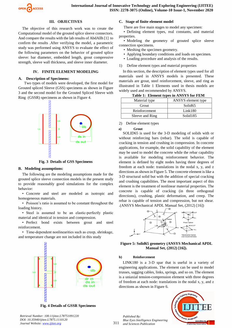
A. Description of Specimens: Two types of models were developed, the first model for
Grouted spliced Sleeve (GSS) specimens as shown in Figure 3 and the second model for the Grouted Spliced Sleeve with Ring (GSSR) specimens as shown in Figure 4.
Fig. 3 Details of GSS Specimens
B. Modeling assumptions:
The following are the modeling assumptions made for the grouted splice sleeve connection models in the present study to provide reasonably good simulations for the complex behavior:
• Concrete and steel are modeled as isotropic and homogeneous materials.
• Poisson’s ratio is assumed to be constant throughout the
loading history. • Steel is assumed to be an elastic‐perfectly plastic
material and identical in tension and compression. • Perfect bond exists between grout and steel
reinforcement. • Time‐dependent nonlinearities such as creep, shrinkage,
and temperature change are not included in this study
Fig. 4 Details of GSSR Specimens
C. Stage of finite element model
There are five main stages to model any specimen: • Defining element types, real constants, and material
properties. • Modeling the geometry of grouted splice sleeve
connection specimens. • Meshing the specimen geometry. • Applying boundary conditions and loads on specimen. • Loading procedure and analysis of the results.
1) Define element types and material properties
In this section, the description of element types used for all materials used in ANSYS models is presented. These materials are grout, steel reinforcement, sleeve, and ring as illustrated in Table 1 Elements used in thesis models are widely used and recommended by ANSYS.
Table 1: Element types in ANSYS for FEM Material type ANSYS element type
Grout Solid65 Reinforcement Link180
Sleeve and Ring Solid185
2) Define element types
a) Grout SOLID65 is used for the 3-D modeling of solids with or
without reinforcing bars (rebar). The solid is capable of cracking in tension and crushing in compression. In concrete applications, for example, the solid capability of the element may be used to model the concrete while the rebar capability is available for modeling reinforcement behavior. The element is defined by eight nodes having three degrees of freedom at each node: translations in the nodal x, y, and z directions as shown in Figure 5. The concrete element is like a 3-D structural solid but with the addition of special cracking and crushing capabilities. The most important aspect of this element is the treatment of nonlinear material properties. The concrete is capable of cracking (in three orthogonal directions), crushing, plastic deformation, and creep. The rebar is capable of tension and compression, but not shear. .(ANSYS Mechanical APDL Manual Set, (2012) [16])
Figure 5: Solid65 geometry (ANSYS Mechanical APDL
Manual Set, (2012) [16]).
b) Reinforcement
LINK180 is a 3-D spar that is useful in a variety of engineering applications. The element can be used to model trusses, sagging cables, links, springs, and so on. The element is a uniaxial tension-compression element with three degrees of freedom at each node: translations in the nodal x, y, and z directions as shown in Figure 6.
Experimental and Analytical Study of Grouted Sleeve Splice Under Axial Tensile Load
312
Published By: Blue Eyes Intelligence Engineering and Sciences Publication
Retrieval Number: 100.1/ijitee.L78751091220 DOI: 10.35940/ijitee.L7875.1110120 Journal Website: www.ijitee.org
Tension-only (cable) and compression-only (gap) options are supported. As in a pin-jointed structure, no bending of the element is considered. Plasticity, creep, rotation, large deflection, and large strain capabilities are included.
By default, LINK180 includes stress-stiffness terms in any analysis that includes large-deflection effects. Elasticity, isotropic hardening plasticity, kinematic hardening plasticity, Hill anisotropic plasticity, Chaboche nonlinear hardening plasticity, and creep are supported. To simulate the tension-/compression-only options, a nonlinear iterative solution approach is necessary; therefore, large-deflection effects must be activated (NLGEOM,ON) prior to the solution phase of the analysis. Added mass, hydrodynamic added mass and loading, and buoyant loading are available. (ANSYS Mechanical APDL Manual Set, (2012) [16]).
Figure 6: Link180 geometry (ANSYS Mechanical
APDL Manual Set, (2012) [16]). c) Sleeve and ring
SOLID185 Structural Solid is suitable for modeling general 3-D solid structures. It allows for prism, tetrahedral, and pyramid degenerations when used in irregular regions. Various element technologies such as B-bar, uniformly reduced integration, and enhanced strains are supported. The geometry and node locations for this element are shown in Figure 7: SOLID185 Homogeneous Structural Solid Geometry. The element is defined by eight nodes and the orthotropic material properties. The default element coordinate system is along global directions. (ANSYS Mechanical APDL Manual Set, (2012) [16]).
Figure 7: Solid185 geometry (ANSYS Mechanical
APDL Manual Set, (2012) [16]). 3) Define material properties
a) Model of grout
Material Model Number 1 refers to the Solid65 element. The Solid65 element requires linear isotropic and multilinear isotropic material properties, in addition to selection of failure criteria of concrete.
• Linear isotropic properties for grout material EX is the modulus of elasticity of the grout (Ec). It was
based on the sika grout data sheet [12] and its equal to 37000MPa. PRXY is the Poisson’s ratio (ν). Poisson’s ratio
was assumed to be 0.2 • Multi linear isotropic properties for grout material The actual compressive strength for grout Fg and the
corresponding strain used to define the multi linear behavior.
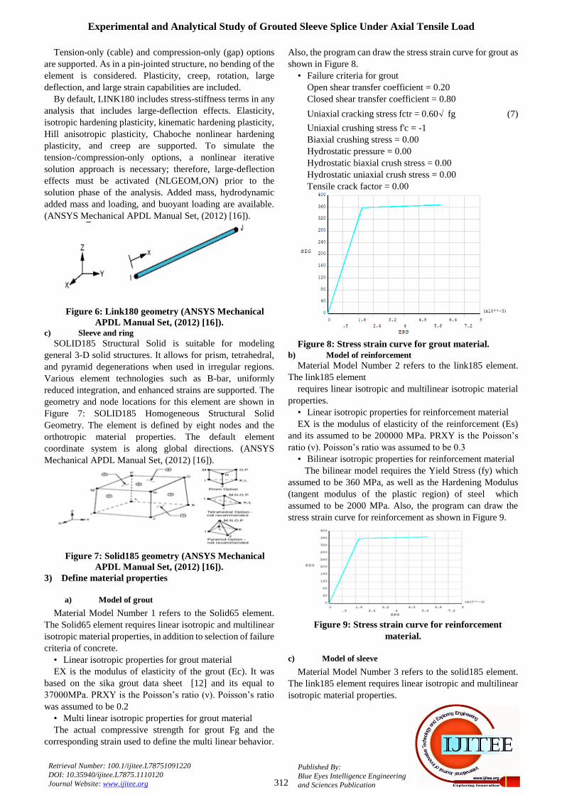
Also, the program can draw the stress strain curve for grout as shown in Figure 8.
• Failure criteria for grout Open shear transfer coefficient = 0.20
Closed shear transfer coefficient = 0.80
Uniaxial cracking stress fctr = 0.60√ fg (7)
Uniaxial crushing stress f'c = -1 Biaxial crushing stress = 0.00 Hydrostatic pressure = 0.00 Hydrostatic biaxial crush stress = 0.00 Hydrostatic uniaxial crush stress = 0.00 Tensile crack factor = 0.00
Figure 8: Stress strain curve for grout material.
b) Model of reinforcement Material Model Number 2 refers to the link185 element.
The link185 element requires linear isotropic and multilinear isotropic material
properties. • Linear isotropic properties for reinforcement material EX is the modulus of elasticity of the reinforcement (Es)
and its assumed to be 200000 MPa. PRXY is the Poisson’s
ratio (ν). Poisson’s ratio was assumed to be 0.3 • Bilinear isotropic properties for reinforcement material The bilinear model requires the Yield Stress (fy) which
assumed to be 360 MPa, as well as the Hardening Modulus (tangent modulus of the plastic region) of steel which assumed to be 2000 MPa. Also, the program can draw the stress strain curve for reinforcement as shown in Figure 9.
Figure 9: Stress strain curve for reinforcement
material.
c) Model of sleeve
Material Model Number 3 refers to the solid185 element. The link185 element requires linear isotropic and multilinear isotropic material properties.
International Journal of Innovative Technology and Exploring Engineering (IJITEE) ISSN: 2278-3075 (Online), Volume-10 Issue-1, November 2020
313
Published By: Blue Eyes Intelligence Engineering and Sciences Publication
Retrieval Number: 100.1/ijitee.L78751091220 DOI: 10.35940/ijitee.L7875.1110120 Journal Website: www.ijitee.org
• Linear isotropic properties for reinforcement material EX is the modulus of elasticity of the reinforcement (Es)
and its assumed to be 200000 MPa. PRXY is the Poisson’s
ratio (ν). Poisson’s ratio was assumed to be 0.3. • Bilinear isotropic properties for reinforcement material The bilinear model requires the Yield Stress (fy) which
assumed to be 240 MPa, as well as the Hardening Modulus (tangent modulus of the plastic region) of steel which assumed to be 0 MPa. Also, the program can draw the stress strain curve for sleeve as shown in Figure 10.
Figure 10: Stress strain curve for Sleeve material.
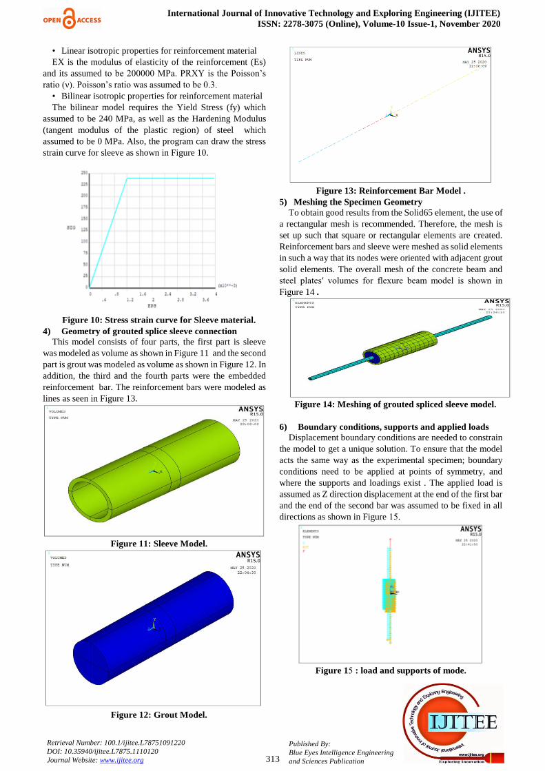
4) Geometry of grouted splice sleeve connection This model consists of four parts, the first part is sleeve
was modeled as volume as shown in Figure 11 and the second part is grout was modeled as volume as shown in Figure 12. In addition, the third and the fourth parts were the embedded reinforcement bar. The reinforcement bars were modeled as lines as seen in Figure 13.
Figure 11: Sleeve Model.
Figure 12: Grout Model.
Figure 13: Reinforcement Bar Model .
5) Meshing the Specimen Geometry To obtain good results from the Solid65 element, the use of
a rectangular mesh is recommended. Therefore, the mesh is set up such that square or rectangular elements are created. Reinforcement bars and sleeve were meshed as solid elements in such a way that its nodes were oriented with adjacent grout solid elements. The overall mesh of the concrete beam and steel platesʹ volumes for flexure beam model is shown in
Figure 14 .
Figure 14: Meshing of grouted spliced sleeve model.
6) Boundary conditions, supports and applied loads
Displacement boundary conditions are needed to constrain the model to get a unique solution. To ensure that the model acts the same way as the experimental specimen; boundary conditions need to be applied at points of symmetry, and where the supports and loadings exist . The applied load is assumed as Z direction displacement at the end of the first bar and the end of the second bar was assumed to be fixed in all directions as shown in Figure 51.
Figure 11 : load and supports of mode.
Experimental and Analytical Study of Grouted Sleeve Splice Under Axial Tensile Load
314
Published By: Blue Eyes Intelligence Engineering and Sciences Publication
Retrieval Number: 100.1/ijitee.L78751091220 DOI: 10.35940/ijitee.L7875.1110120 Journal Website: www.ijitee.org
7) Setting nonlinear solution parameters Setting solution parameters involves defining the analysis
type and common analysis options for an analysis, as well as specifying load step options for it. To ignore large deformation effects such as large deflection, large rotation, and large strain; the analysis option was set to (Small Displacement Static).
In nonlinear analysis, the load applied to the structures must be increased gradually to avoid non‐convergence. The
total load applied to a finite element model is divided into a series of load increments called load steps. At the completion of each incremental solution, the stiffness changes in structural stiffness before proceeding to the next load increment.
The ANSYS program uses Newton–Raphson equilibrium iterations for updating the model stiffness. Automatic time stepping in the ANSYS program predicts and controls load step sizes. Based on the previous solution history and the physics of the models, if the convergence behavior is smooth, automatic time stepping will increase the load increment up to a selected maximum load step size. If the convergence behavior is abrupt, automatic time stepping will bisect the load increment until it is equal to a selected minimum load step size. The maximum and minimum load step sizes are required for the automatic time stepping.
Nonlinear Static Analysis type was utilized for grouted splice sleeve.
V. VERIFICATION OF ANSYS FINITE ELEMENT
MODELS
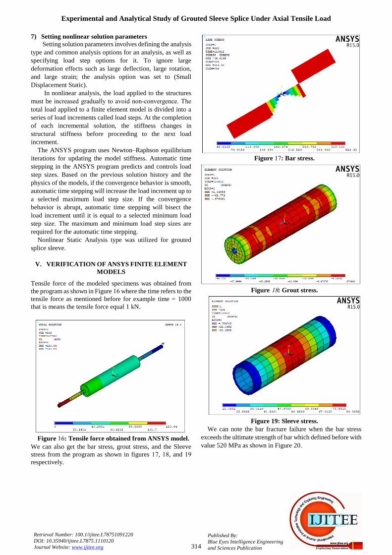
Tensile force of the modeled specimens was obtained from the program as shown in Figure 51 where the time refers to the tensile force as mentioned before for example time = 1000 that is means the tensile force equal 1 kN.
Figure 51: Tensile force obtained from ANSYS model.
We can also get the bar stress, grout stress, and the Sleeve stress from the program as shown in figures 51, 51, and 51 respectively.
Figure 51: Bar stress.
Figure 51: Grout stress.
Figure 19: Sleeve stress.
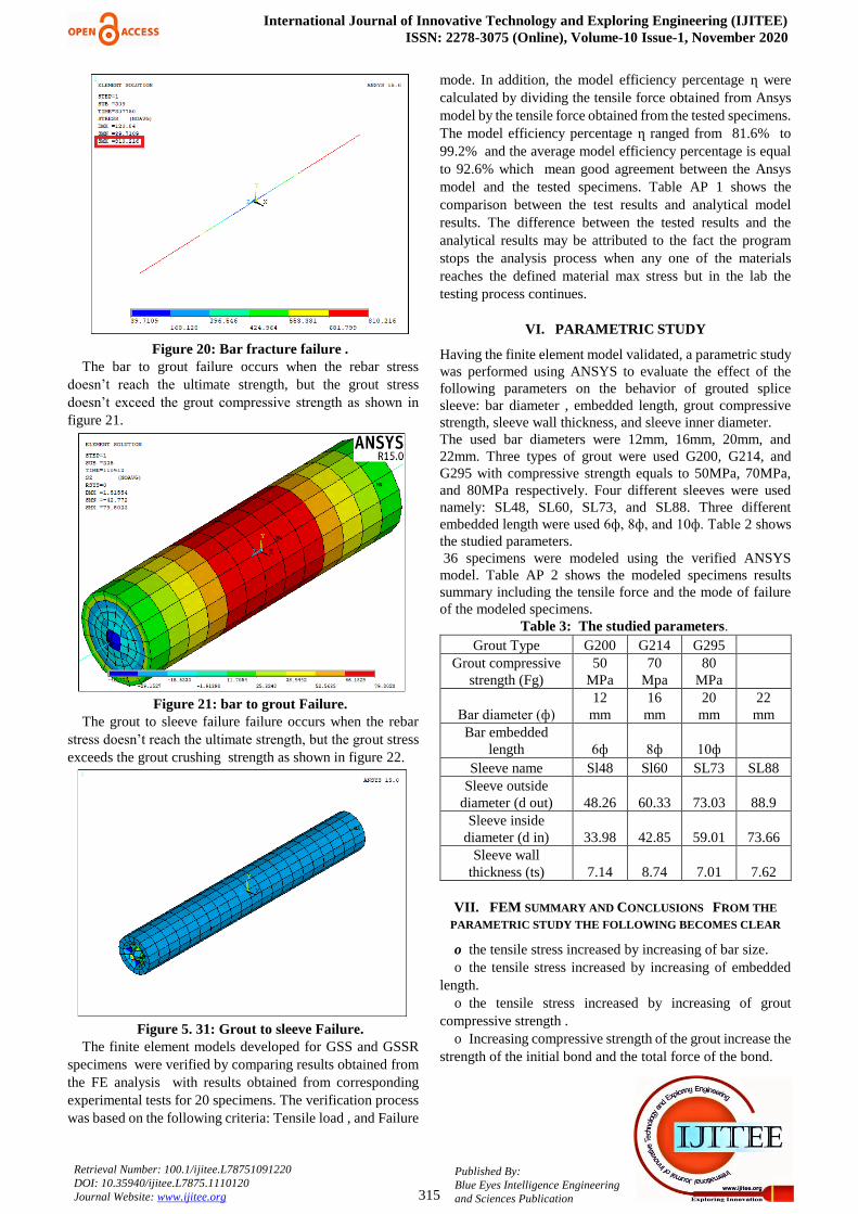
We can note the bar fracture failure when the bar stress exceeds the ultimate strength of bar which defined before with value 520 MPa as shown in Figure 20.
International Journal of Innovative Technology and Exploring Engineering (IJITEE) ISSN: 2278-3075 (Online), Volume-10 Issue-1, November 2020
315
Published By: Blue Eyes Intelligence Engineering and Sciences Publication
Retrieval Number: 100.1/ijitee.L78751091220 DOI: 10.35940/ijitee.L7875.1110120 Journal Website: www.ijitee.org
Figure 20: Bar fracture failure .
The bar to grout failure occurs when the rebar stress doesn’t reach the ultimate strength, but the grout stress doesn’t exceed the grout compressive strength as shown in
figure 21.
Figure 21: bar to grout Failure.
The grout to sleeve failure failure occurs when the rebar stress doesn’t reach the ultimate strength, but the grout stress exceeds the grout crushing strength as shown in figure 22.
Figure 5. 31: Grout to sleeve Failure.
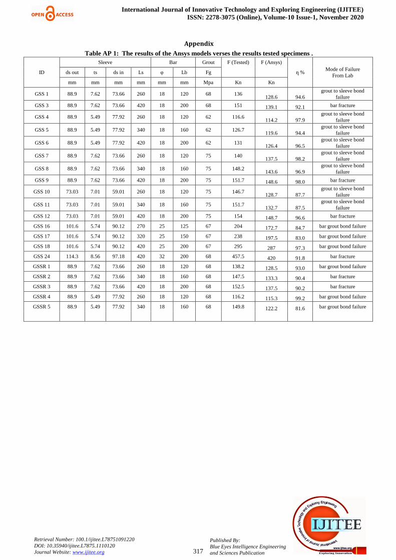
The finite element models developed for GSS and GSSR specimens were verified by comparing results obtained from the FE analysis with results obtained from corresponding experimental tests for 20 specimens. The verification process was based on the following criteria: Tensile load , and Failure
mode. In addition, the model efficiency percentage ղ were calculated by dividing the tensile force obtained from Ansys model by the tensile force obtained from the tested specimens. The model efficiency percentage ղ ranged from 81.6% to 99.2% and the average model efficiency percentage is equal to 92.6% which mean good agreement between the Ansys model and the tested specimens. Table AP 1 shows the comparison between the test results and analytical model results. The difference between the tested results and the analytical results may be attributed to the fact the program stops the analysis process when any one of the materials reaches the defined material max stress but in the lab the testing process continues.
VI. PARAMETRIC STUDY
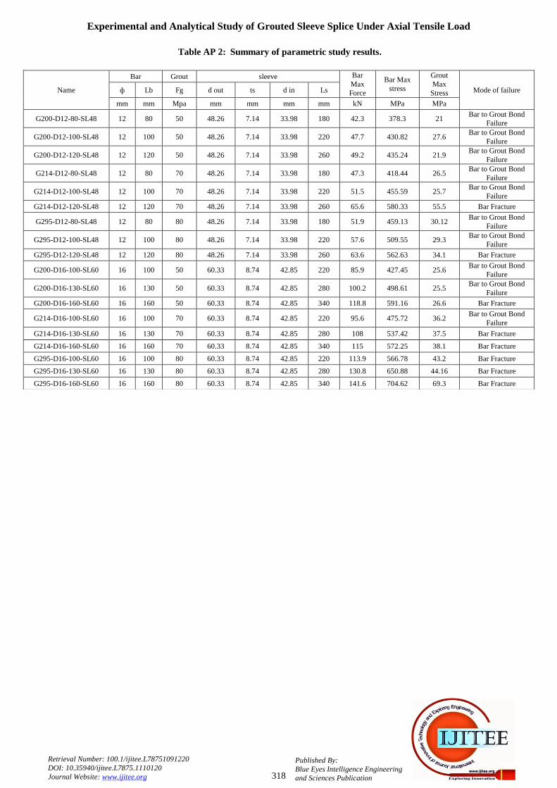
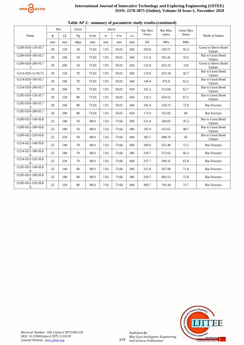
Having the finite element model validated, a parametric study was performed using ANSYS to evaluate the effect of the following parameters on the behavior of grouted splice sleeve: bar diameter , embedded length, grout compressive strength, sleeve wall thickness, and sleeve inner diameter. The used bar diameters were 12mm, 16mm, 20mm, and 22mm. Three types of grout were used G200, G214, and G295 with compressive strength equals to 50MPa, 70MPa, and 80MPa respectively. Four different sleeves were used namely: SL48, SL60, SL73, and SL88. Three different embedded length were used 6ф, 8ф, and 10ф. Table 2 shows the studied parameters. 36 specimens were modeled using the verified ANSYS model. Table AP 2 shows the modeled specimens results summary including the tensile force and the mode of failure of the modeled specimens.
Table 3: The studied parameters.
Grout Type G200 G214 G295 Grout compressive
strength (Fg) 50
MPa 70
Mpa 80
MPa
Bar diameter (ф) 12
mm 16
mm 20
mm 22
mm Bar embedded
length 6ф 8ф 10ф Sleeve name Sl48 Sl60 SL73 SL88
Sleeve outside diameter (d out) 48.26 60.33 73.03 88.9
Sleeve inside diameter (d in) 33.98 42.85 59.01 73.66
Sleeve wall thickness (ts) 7.14 8.74 7.01 7.62
VII. FEM SUMMARY AND CONCLUSIONS FROM THE
PARAMETRIC STUDY THE FOLLOWING BECOMES CLEAR
o the tensile stress increased by increasing of bar size. o the tensile stress increased by increasing of embedded
length. o the tensile stress increased by increasing of grout
compressive strength . o Increasing compressive strength of the grout increase the
strength of the initial bond and the total force of the bond.

Experimental and Analytical Study of Grouted Sleeve Splice Under Axial Tensile Load
316
Published By: Blue Eyes Intelligence Engineering and Sciences Publication
Retrieval Number: 100.1/ijitee.L78751091220 DOI: 10.35940/ijitee.L7875.1110120 Journal Website: www.ijitee.org
o with the increase of embedded length, bar diameter, and wall thickness the total bond strength increases.
o Increasing the diameter of the inside sleeve reduces the total strength of the bond.
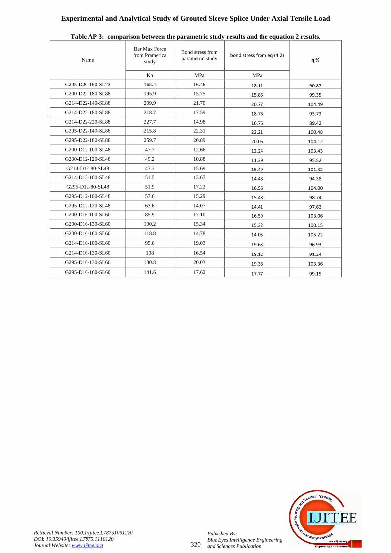
o the model efficiency percentage ղ ranged from 89.42% to 105.22% and the average model efficiency percentage is equal to 99.88% which mean good agreement between the Ansys model and the tested specimens. Table AP 3 shows the comparison between the parametric study results and derived equation 2 results.
VIII. CONCLUSIONS
• Increasing compressive strength of the grout increase the strength of the initial bond and the total force of the bond.
• With the increase of embedded length, bar diameter, and wall thickness the total bond strength increases.
• Increasing the diameter of the inside sleeve reduces the total strength of the bond.
• The addition of interlocking steel rings at both ends of the interior sleeve wall greatly improved the grouted bar splice 's tensile capacity. constraining the grout within the sleeve prevents the grout-sleeve bond and enhances the confining stress which also increases the bar-grout bond strength.
• The introduction to both ends of the inner sleeve wall of interlocking steel rings with a minimum thickness of 7 mm
was adequate and the tensile strength of the spliced bars was achieved. The steel rings prevent the grout the grout to sleeve bond failure.
• Finite element model using ANSYS was successfully verified comparing with experimental test results. Therefore, ANSYS can be confidently used in analysis of grouted splice sleeve connection.
• The average efficiency of the finite element models using ANSYS was 92.5%.
REFERENCES
1. AbdAllh Mostafa "The Mechanical behavior of grouted sleeve splice connections with and without mechanical interlocking ring under axial tensile load"2020.
2. ACI 318 -14 (2014), Building Code Requirements for Structural Concrete and Commentary, Building Code Requirements for Structural Concrete (ACI 318-14) An ACI Standard Commentary on Building Code Requirements for Structural Concrete (ACI 318 R-14) An ACI Report, Ameri can Concrete Institute; Michigan, United States.
3. ASTM A106 Grade B, ASTM A106 / A106M - 15 Standard Specification for Seamless Carbon Steel Pipe for High-Temperature Service; ASTM INTERNATIONAL. (2015) https : // www . ast m.org/Standards/ A106 .htm
4. Belal Ali “Experimental study of the mechanical behavior of grouted
spliced sleeve connections for precast conc rete construction under axial load” 2016.
5. Coogler KL, Harries KA, Gall ick M. Experimental study of offset mechanical lap splice behavior. A.C.I. Struct J 2008 ; 105 (4 ) : 478 – 87
6. Darwin, ZuoJ, TholenML, Idun EK. Development length criteria for conventional and high relative rib area rein forcing bars. ACI Struct J 1996 ;93 (3) : 1–13.
7. ECP (2018), Egyptian Code of Practice: ECP 203 - 2007, Egyptian Code for De sign and Construction of Conc rete Structures (ECP 203 - 2018 ), Housing and Building National Research Center; Giza, Egypt.
8. Einea, and Tadros, M.K. (1995), “Grout-Filled Pipe Splices for Precast Concrete Const ruction”, P. C. I Journal , 40 (1) , 82–93.
9. Jansson PO. Evaluation of grout-filled mechanical splices for precast concrete, Construction. T. I. -2094; 2008
10. Lutz, L. A., and Gergely, P., Mechanics of Bond and Slip of De formed Bars in Concrete, ACI. Journal, Ameri can Concrete Institute, Vol. 64 , No . 11 , 1967
11. Mahdi, M., Ah. mad, J., and Ar. ash, K. 2003, Bond of cement grouted rein forcing bars under constant radial pressure, Master Project, University Technology Malaysia, 2003
12. S I K A grout ® 200 (2015), SIKA grout® -200 High strength, Non-shrink, None oxidized Cementitious Grout; Sika Egypt for Construction Chemicals, El Abour City, Egypt.
13. Soroushian P, Ch. oi KB, Park GH, Asl. ani F. Bond of deformed bars to concrete effects of confinement and strength of concrete. A. C. I.
Mater J 1991 ; 88 (3) : 227 – 32. 14. Thompson JN. Lap ped splices in rein forced concrete beams. Proc J
Am Concrete Inst 1955 ; 52 (2) : 201 – 12. 15. Untrauer RE, Henry RL. Influence of normal pressure on bond
strength. A. C. I. J 1965 ; 62(5) :5 16. Manual, A. U. S. (2015). ANSYS Mechanical APDL Technology
Demonstration Guide. Canonsburg, ANSYS Inc, USA.
AUTHORS PROFILE
Abdallh M.Soliman - PhD student at structural department faculty of engineering Cairo university. He has master’s in science in concrete to his credit.
His area of research is precast concrete specially the splice between concrete and steel reinforcement. He has published paper in the field of concrete - concrete composite section
Hatem H. Ibrahim- he is an assistant professor in department of structural at faculty of engineering Cairo university. He has master’s in science from
Cairo university and PhD degree from university of Alberta Canada .
Hossma A. Hodhod - he is a professor in department structural at faculty of engineering Cairo university. He has master’s in science from Cairo
university and PhD degree from university of Tokyo. He has published many papers in the field of properties and strength of materials.
International Journal of Innovative Technology and Exploring Engineering (IJITEE) ISSN: 2278-3075 (Online), Volume-10 Issue-1, November 2020
317
Published By: Blue Eyes Intelligence Engineering and Sciences Publication
Retrieval Number: 100.1/ijitee.L78751091220 DOI: 10.35940/ijitee.L7875.1110120 Journal Website: www.ijitee.org
Appendix
Table AP 1: The results of the Ansys models verses the results tested specimens .
ID
Sleeve Bar Grout F (Tested) F (Ansys)
ղ % Mode of Failure
From Lab ds out ts ds in Ls φ Lb Fg
mm mm mm mm mm mm Mpa Kn Kn
GSS 1 88.9 7.62 73.66 260 18 120 68 136 128.6 94.6
grout to sleeve bond failure
GSS 3 88.9 7.62 73.66 420 18 200 68 151 139.1 92.1 bar fracture
GSS 4 88.9 5.49 77.92 260 18 120 62 116.6 114.2 97.9
grout to sleeve bond failure
GSS 5 88.9 5.49 77.92 340 18 160 62 126.7 119.6 94.4
grout to sleeve bond failure
GSS 6 88.9 5.49 77.92 420 18 200 62 131 126.4 96.5
grout to sleeve bond failure
GSS 7 88.9 7.62 73.66 260 18 120 75 140 137.5 98.2
grout to sleeve bond failure
GSS 8 88.9 7.62 73.66 340 18 160 75 148.2 143.6 96.9
grout to sleeve bond failure
GSS 9 88.9 7.62 73.66 420 18 200 75 151.7 148.6 98.0 bar fracture
GSS 10 73.03 7.01 59.01 260 18 120 75 146.7 128.7 87.7
grout to sleeve bond failure
GSS 11 73.03 7.01 59.01 340 18 160 75 151.7 132.7 87.5
grout to sleeve bond failure
GSS 12 73.03 7.01 59.01 420 18 200 75 154 148.7 96.6 bar fracture
GSS 16 101.6 5.74 90.12 270 25 125 67 204 172.7 84.7 bar grout bond failure
GSS 17 101.6 5.74 90.12 320 25 150 67 238 197.5 83.0 bar grout bond failure
GSS 18 101.6 5.74 90.12 420 25 200 67 295 287 97.3 bar grout bond failure
GSS 24 114.3 8.56 97.18 420 32 200 68 457.5 420 91.8 bar fracture
GSSR 1 88.9 7.62 73.66 260 18 120 68 138.2 128.5 93.0 bar grout bond failure
GSSR 2 88.9 7.62 73.66 340 18 160 68 147.5 133.3 90.4 bar fracture
GSSR 3 88.9 7.62 73.66 420 18 200 68 152.5 137.5 90.2 bar fracture
GSSR 4 88.9 5.49 77.92 260 18 120 68 116.2 115.3 99.2 bar grout bond failure
GSSR 5 88.9 5.49 77.92 340 18 160 68 149.8 122.2 81.6 bar grout bond failure
Experimental and Analytical Study of Grouted Sleeve Splice Under Axial Tensile Load
318
Published By: Blue Eyes Intelligence Engineering and Sciences Publication
Retrieval Number: 100.1/ijitee.L78751091220 DOI: 10.35940/ijitee.L7875.1110120 Journal Website: www.ijitee.org
Table AP 2: Summary of parametric study results.
Name
Bar Grout sleeve Bar Max Force
Bar Max stress
Grout Max
Stress Mode of failure ф Lb Fg d out ts d in Ls
mm mm Mpa mm mm mm mm kN MPa MPa
G200-D12-80-SL48 12 80 50 48.26 7.14 33.98 180 42.3 378.3 21 Bar to Grout Bond
Failure
G200-D12-100-SL48 12 100 50 48.26 7.14 33.98 220 47.7 430.82 27.6 Bar to Grout Bond
Failure
G200-D12-120-SL48 12 120 50 48.26 7.14 33.98 260 49.2 435.24 21.9 Bar to Grout Bond
Failure
G214-D12-80-SL48 12 80 70 48.26 7.14 33.98 180 47.3 418.44 26.5 Bar to Grout Bond
Failure
G214-D12-100-SL48 12 100 70 48.26 7.14 33.98 220 51.5 455.59 25.7 Bar to Grout Bond
Failure
G214-D12-120-SL48 12 120 70 48.26 7.14 33.98 260 65.6 580.33 55.5 Bar Fracture
G295-D12-80-SL48 12 80 80 48.26 7.14 33.98 180 51.9 459.13 30.12 Bar to Grout Bond
Failure
G295-D12-100-SL48 12 100 80 48.26 7.14 33.98 220 57.6 509.55 29.3 Bar to Grout Bond
Failure
G295-D12-120-SL48 12 120 80 48.26 7.14 33.98 260 63.6 562.63 34.1 Bar Fracture
G200-D16-100-SL60 16 100 50 60.33 8.74 42.85 220 85.9 427.45 25.6 Bar to Grout Bond
Failure
G200-D16-130-SL60 16 130 50 60.33 8.74 42.85 280 100.2 498.61 25.5 Bar to Grout Bond
Failure
G200-D16-160-SL60 16 160 50 60.33 8.74 42.85 340 118.8 591.16 26.6 Bar Fracture
G214-D16-100-SL60 16 100 70 60.33 8.74 42.85 220 95.6 475.72 36.2 Bar to Grout Bond
Failure
G214-D16-130-SL60 16 130 70 60.33 8.74 42.85 280 108 537.42 37.5 Bar Fracture
G214-D16-160-SL60 16 160 70 60.33 8.74 42.85 340 115 572.25 38.1 Bar Fracture
G295-D16-100-SL60 16 100 80 60.33 8.74 42.85 220 113.9 566.78 43.2 Bar Fracture
G295-D16-130-SL60 16 130 80 60.33 8.74 42.85 280 130.8 650.88 44.16 Bar Fracture
G295-D16-160-SL60 16 160 80 60.33 8.74 42.85 340 141.6 704.62 69.3 Bar Fracture
International Journal of Innovative Technology and Exploring Engineering (IJITEE) ISSN: 2278-3075 (Online), Volume-10 Issue-1, November 2020
319
Published By: Blue Eyes Intelligence Engineering and Sciences Publication
Retrieval Number: 100.1/ijitee.L78751091220 DOI: 10.35940/ijitee.L7875.1110120 Journal Website: www.ijitee.org
Table AP 2: summary of parametric study results.(continued)
Name
Bar Grout sleeve Bar Max Force
Bar Max stress
Grout Max Stress Mode of failure ф Lb Fg d out ts d in Ls
mm mm Mpa mm mm mm mm kN MPa MPa
G200-D20-120-SL73
20 120 50 73.03 7.01 59.01 260 103.8 330.57 95.4 Grout to Sleeve Bond
Failure G200-D20-160-SL7
3 20 160 50 73.03 7.01 59.01 340 111.6 355.41 33.2
Bar to Grout Bond Failure
G200-D20-200-SL73
20 200 50 73.03 7.01 59.01 420 132.9 423.25 110 Grout to Sleeve Bond
Failure
G214-D20-12-SL73 20 120 70 73.03 7.01 59.01 260 110.9 353.18 42.7 Bar to Grout Bond
Failure G214-D20-160-SL7
3 20 160 70 73.03 7.01 59.01 340 149.4 475.8 62.2
Bar to Grout Bond Failure
G214-D20-200-SL73
20 200 70 73.03 7.01 59.01 420 161.3 513.69 61.7 Bar to Grout Bond
Failure G295-D20-120-SL7
3 20 120 80 73.03 7.01 59.01 260 133.3 424.52 67.2
Bar to Grout Bond Failure
G295-D20-160-SL73
20 160 80 73.03 7.01 59.01 340 165.4 526.75 72.8 Bar Fracture
G295-D20-200-SL73
20 200 80 73.03 7.01 59.01 420 173.9 553.82 60 Bar Fracture
G200-D22-140-SL88
22 140 50 88.9 7.62 73.66 300 121.6 320.05 35.2 Bar to Grout Bond
Failure G200-D22-180-SL8
8 22 180 50 88.9 7.62 73.66 380 195.9 515.61 48.7
Bar to Grout Bond Failure
G200-D22-220-SL88
22 220 50 88.9 7.62 73.66 460 185.7 488.76 45 Bar to Grout Bond
Failure G214-D22-140-SL8
8 22 140 70 88.9 7.62 73.66 300 209.9 552.46 72.2 Bar Fracture
G214-D22-180-SL88
22 180 70 88.9 7.62 73.66 380 218.7 575.62 66.3 Bar Fracture
G214-D22-220-SL88
22 220 70 88.9 7.62 73.66 460 227.7 599.31 61.9 Bar Fracture
G295-D22-140-SL88
22 140 80 88.9 7.62 73.66 300 215.8 567.98 71.8 Bar Fracture
G295-D22-180-SL88
22 180 80 88.9 7.62 73.66 380 259.7 683.53 72.8 Bar Fracture
G295-D22-220-SL88
22 220 80 88.9 7.62 73.66 460 300.7 791.44 75.7 Bar Fracture
Experimental and Analytical Study of Grouted Sleeve Splice Under Axial Tensile Load
320
Published By: Blue Eyes Intelligence Engineering and Sciences Publication
Retrieval Number: 100.1/ijitee.L78751091220 DOI: 10.35940/ijitee.L7875.1110120 Journal Website: www.ijitee.org
Table AP 3: comparison between the parametric study results and the equation 2 results.
Name
Bar Max Force from Pramerica
study
Bond stress from parametric study
bond stress from eq (4.2) ղ %
Kn MPa MPa
G295-D20-160-SL73 165.4 16.46 18.11 90.87
G200-D22-180-SL88 195.9 15.75 15.86 99.35
G214-D22-140-SL88 209.9 21.70 20.77 104.49
G214-D22-180-SL88 218.7 17.59 18.76 93.73
G214-D22-220-SL88 227.7 14.98 16.76 89.42
G295-D22-140-SL88 215.8 22.31 22.21 100.48
G295-D22-180-SL88 259.7 20.89 20.06 104.12
G200-D12-100-SL48 47.7 12.66 12.24 103.43
G200-D12-120-SL48 49.2 10.88 11.39 95.52
G214-D12-80-SL48 47.3 15.69 15.49 101.32
G214-D12-100-SL48 51.5 13.67 14.48 94.38
G295-D12-80-SL48 51.9 17.22 16.56 104.00
G295-D12-100-SL48 57.6 15.29 15.48 98.74
G295-D12-120-SL48 63.6 14.07 14.41 97.62
G200-D16-100-SL60 85.9 17.10 16.59 103.06
G200-D16-130-SL60 100.2 15.34 15.32 100.15
G200-D16-160-SL60 118.8 14.78 14.05 105.22
G214-D16-100-SL60 95.6 19.03 19.63 96.93
G214-D16-130-SL60 108 16.54 18.12 91.24
G295-D16-130-SL60 130.8 20.03 19.38 103.36
G295-D16-160-SL60 141.6 17.62 17.77 99.15
Related Documents