Experiment 3 – Wireless Transceiver Group Two Mathieu Perreault (260158758) Logan Smyth (260179735) Presented October 25th, 2009 1

Welcome message from author
This document is posted to help you gain knowledge. Please leave a comment to let me know what you think about it! Share it to your friends and learn new things together.
Transcript
Experiment 3 – Wireless Transceiver Group Two
Mathieu Perreault (260158758)Logan Smyth (260179735)
Presented October 25th, 2009
1
1. FUNCTIONAL SPECIFICATIONS
This experiment’s main goal was to make us understand SPI by implementing it on our McGumps board, which is based on the MSP430 chip. We used SPI to interface to the CC2500 wireless transceiver, which is built by Texas Instruments, the same company that develops the MSP430 chip. We were provided with the CC2500 as well as its different specifications and datasheet.
The deliverable of this experiment is a menu-driven application running autonomously on the McGumps board that provides an interface to this wireless module. The different specifications, taken from the Experiment 3 PDF are as follows:
Function: Hardware SPI interface between MSP430 and CC2500Purpose: Provide a data link in order to transmit and receive data and commands and provide timing diagrams for demonstration of data transfer. Inputs: Data to be sent to the CC2500 and outward via the wireless or control signals to read and write registersOutputs: Data read from registers and incoming data from the wireless
Function: User interface outputting to a PC Serial terminal in order to interact with the systemPurpose: Allow us to interactively query the status of the CC2500, read all of it's registers, modify all of it's registers, and allow us to view the data received from the wireless.Inputs: Keyboard input via a terminal, transmitted via UART in order to control a menu and enables entry of address and data values.Outputs: Text via a terminal showing a menu and possibly register values and interactive data entry windows.
Function: Subroutines for configuring the CC2500, receiving data and transmitting data.Purpose: To allow us to transmit and receive data via wireless.Inputs: A buffer of bytes to be transmitted.Outputs: A series of bytes received as packet.
Summary• Use the USART (Synchronous UART) present on the MSP430 to develop the SPI functionality.• Be able to send and receive packets of less than 64 bytes.• The UART used to communicate the menu-driven application should use parameters of 57600 baud rate,
no parity bit, 8 data bits and 1 stop bit. • (Implicit) The application and its menu should be intuitive.• The board must operate independently of the parallel port connection to Rowley Associates “Crossworks
1.3”• The implementation should route the SPI port through the CPLD (MSP430 port 5) on the McGumps
board. The data lines should come out of the H1 header of the board to the CC2500.• Part 1: Capture strobes and read/write commands using the Ant16 logic analyzer available in the Lab.• Part 2: Provide an interface to modify and display the CC2500 registers.• In this interface, the user presses Enter to confirm a choice and Escape to cancel an input.• Part 3: Receive wireless packets and display them in the application.
2
2. IMPLEMENTATION
CPLD ConfigurationThe MSP430's USART1 pins are connected directly to the CPLD on the McGumps board, requiring us to flash the CPLD with logic to direct the pins. Using VHDL, we redirected the lower 4 pins of the MSP430's port 5 to route to the H1 header. Three pins(SOMI,STE,and CLK) are set as inputs from the MSP430 and as outputs on the H1 header while one pin (SIMO) is an input from the H1 header and output to the MSP430.
As a side note, we also configured the Port1 vector to be an input to the CPLD since otherwise, interference is created for the operation of the keypad, which uses Port 1 extensively (we understand the keypad is not used in this lab, although it might be used in the final project).
SPI ConfigurationAs specified in the functional requirements for this experiment, the SPI was implemented using the USART module of the MSP430. More specifically, since the program already uses the UART0 for Terminal communication, UART1 was used for SPI. The UART settings to configure SPI are not much different than for using the terminal, but the differences will be highlighted here.
• For simplicity, the 57.6KHz clock used in UART0 is reused for UART1.• The SPI requires that the CKPH (Clock phase) be entered as a parameter, which guarantees that the data
will be sampled on the rising edge of the clock. The other available parameter of clock polarity was not used since the default value of idling low was the one specified in the CC2500 SPI specifications.
• As well, the three-wire SPI mode was selected by setting the STC bit in the U1TCTL register. The fourth wire of SPI, the STE control line, is driven manually.
• Control bits SYNC and MM were configured to enable the SPI functionality of the MSP on UART1.• Since the UART1 pins are going through port 5, the P5 selection bits were set appropriately and the
direction of each pin as well.
We implemented a function to work with the SPI to send a byte and return the value received during transmission. This function was also made to support transactions, so the STE line can be put into a specified state and held there until a multi-byte transfer has been completed.
CC2500 ConfigurationWe have implemented a reset a reset routine, as specified on the CC2500 data sheet, in order to reset it to a known state after power up is complete. The routine requires the pulling low and high of different pins on the SPI link as well as sending the SRES (software reset) strobe to the CC2500. This was confirmed to be working and further work showed that the chip is going in IDLE mode after our reset, as expected.
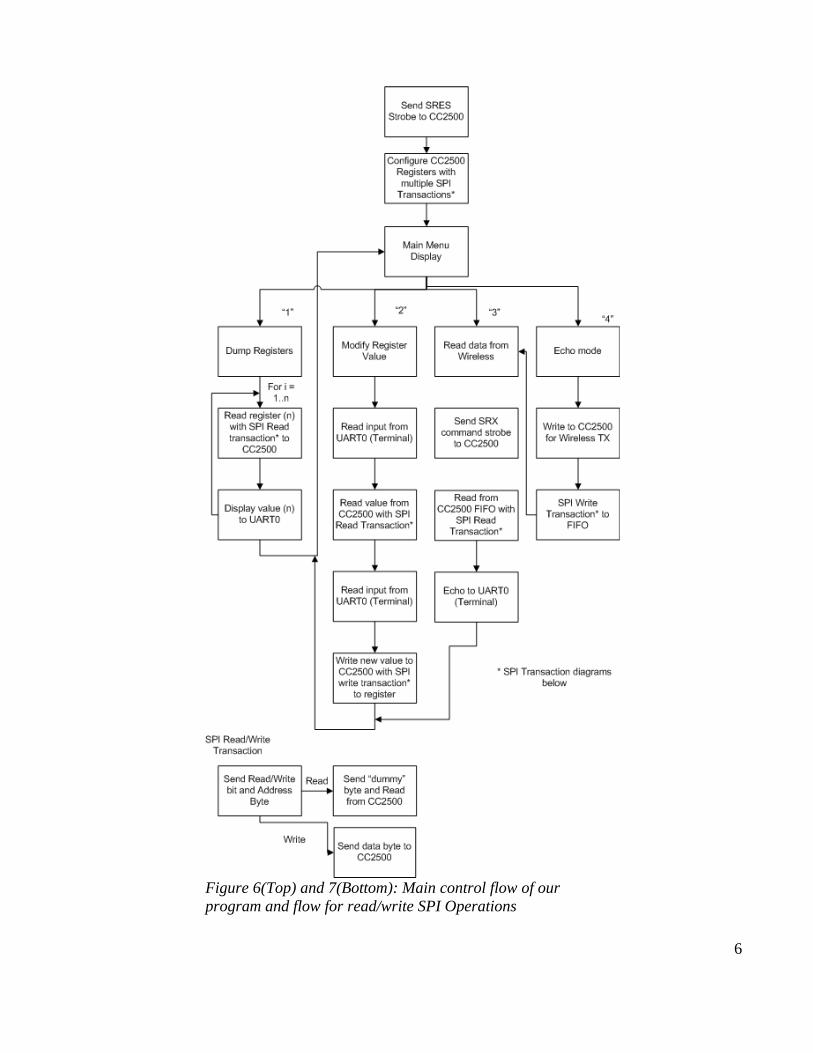
Methods to do a simple read or write as well as send command strobes were implemented simply by using our SPI API function to begin a transaction and send a single byte or a burst of data. Using these, it becomes possible to read or write to a register on the CC2500 and begin configuration of many control registers. See figure 7 for a simple diagram.
The provided values for control of frequency, channel, packet control and so on are loaded into the CC2500 after the power on reset is complete, and from then on the chip waits in the IDLE state.
With the chip waiting in the IDLE state, it is ready to receive or transmit. To receive, we send the SRX control strobe, at which point it will wait for an incoming packet and load the packet into the RX buffer, where is it read into the MSP by repeated reads to the RXBUF FIFO register. Transmitting is accomplished in a similar
3
fashion. The TX buffer is loaded with the data to be transmitted by repeated writes to the TXBUF FIFO register, to a maximum of 64 bytes, at which point the STX control strobe is fired and all data is transmitted.
Menu SystemThe menu system is implemented as a state machine, with each options executing a separate function. See figure 6 for a full flow of the menu and control system. The menu options are the following.
• Dump all registers, which loops over all of the registers and prints the name, address and value of them.• Modify Register, which requests an address, displays the current value, and requests a new value, which it
will write back to the CC2500.• Read Data, which receives and and displays values from the RX buffer of the CC2500.• Echo Data, which transmits a value and reads back the response.
3. PERFORMANCE
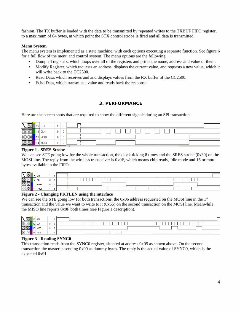
Here are the screen shots that are required to show the different signals during an SPI transaction.
Figure 1 - SRES StrobeWe can see STE going low for the whole transaction, the clock ticking 8 times and the SRES strobe (0x30) on the MOSI line. The reply from the wireless transceiver is 0x0F, which means chip ready, Idle mode and 15 or more bytes available in the FIFO.
Figure 2 - Changing PKTLEN using the interfaceWe can see the STE going low for both transactions, the 0x06 address requested on the MOSI line in the 1st
transaction and the value we want to write to it (0x55) on the second transaction on the MOSI line. Meanwhile, the MISO line reports 0x0F both times (see Figure 1 description).
Figure 3 - Reading SYNC0This transaction reads from the SYNC0 register, situated at address 0x05 as shown above. On the second transaction the master is sending 0x00 as dummy bytes. The reply is the actual value of SYNC0, which is the expected 0x91.
4
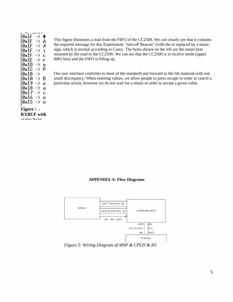
This figure illustrates a read from the FIFO of the CC2500. We can clearly see that it contains the required message for this Experiment: “microP Beacon” (with the m replaced by a music sign, which is normal according to Casey. The bytes shown on the left are the status byte returned by the read to the CC2500. We can see that the CC2500 is in receive mode (upper 0001 bits) and the FIFO is filling up.
Our user interface conforms to most of the standards put forward in the lab material,with one small discrepancy. When entering values, we allow people to press escape in order to cancel a particular action, however we do not wait for a return in order to accept a given value.
APPENDIX A: Flow Diagrams
5
Figure -4 RXBUF with status byte
Figure 5: Wiring Diagram of MSP & CPLD & H1
6
Figure 6(Top) and 7(Bottom): Main control flow of our program and flow for read/write SPI Operations
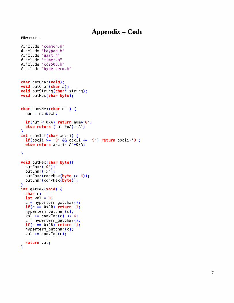
Appendix – CodeFile: main.c
#include "common.h"#include "keypad.h"#include "uart.h"#include "timer.h"#include "cc2500.h"#include "hyperterm.h"
char getChar(void);void putChar(char a);void putString(char* string);void putHex(char byte);
char convHex(char num) { num = num&0xF;
if(num < 0xA) return num+'0'; else return (num-0xA)+'A';}int convInt(char ascii) { if(ascii >= '0' && ascii <= '9') return ascii-'0'; else return ascii-'A'+0xA; }
void putHex(char byte){ putChar('0'); putChar('x'); putChar(convHex(byte >> 4)); putChar(convHex(byte));}int getHex(void) { char c; int val = 0; c = hyperterm_getchar(); if(c == 0x1B) return -1; hyperterm_putchar(c); val += convInt(c) << 4; c = hyperterm_getchar(); if(c == 0x1B) return -1; hyperterm_putchar(c); val += convInt(c);
return val;}
7
/** * Loop over all registers and print address, name and current value */void dump_registers(void) { int i; char data; char* name = NULL; uart_switch(USE_UART0); putString("\r\n"); for(i = 0; i < 0xFF; i++) { name = cc2500_reg_get_name(i); if(name != NULL){ data = cc2500_read_reg(i); uart_switch(USE_UART0); putHex(i); putString(" : "); putString(name); putString(" = "); putHex(data); putString("\r\n"); } } putString("\r\nStatus: "); data = cc2500_status(); putHex(data);
putString("\r\n");
}
/** * Request register address, display current value, and request new value */void modify_registers(void) { int addr; int val; char* name; uart_switch(USE_UART0); putString("What register would you like to modify?\r\n: 0x"); addr = getHex(); if(addr == -1){ putString("\r\n"); return; } name = cc2500_reg_get_name(addr);
putString("\r\n"); if(name == NULL) {
8
putString("Invalid Register Address\r\n"); } else { putString("Register Modification for "); putString(name); putString("("); putHex(addr); putString(")"); putString(":\r\nValue = ");
val = cc2500_read_reg(addr); uart_switch(USE_UART0);
putHex(val); putString(" changed to => 0x"); val = getHex(); if(val == -1){ putString("\r\n"); return; } cc2500_write_reg(addr, val); }}
/** * Read data from the RXBUF of the CC2500 and dump to terminal */void read_data(void) { char val; int i; int size = 0;
uart_switch(CC2500_UART); uart_spi_byte(CC2500REG_SRX, SPI_SINGLE_TRANS); //Put in receive mode //timer_wait(100);
for(i = 0; i < 15; i++) { val = cc2500_read_reg(CC2500REG_DATABUF);
uart_switch(USE_UART0); putHex(cc2500_status()); putString(" -> "); //putHex(val); putChar(val); putString("\r\n"); } putString("\r\n");}
9
/** * Transmit data then proceed as above */void echo_data(void) { char* data = "OHGODNOOOOO", val; int i;
cc2500_transmit_packet(data, 12); uart_switch(CC2500_UART); uart_spi_byte(CC2500REG_SRX, SPI_SINGLE_TRANS); //Put in receive mode //timer_wait(100);
//size = cc2500_read_reg(CC2500REG_RXBYTES);
for(i = 0; i < 64; i++) { //while(TRUE) { val = cc2500_read_reg(CC2500REG_DATABUF); //size = cc2500_read_reg(CC2500REG_RXBYTES);
uart_switch(USE_UART0); putHex(cc2500_status()); putString(" -> "); //putHex(val); putChar(val); putString("\r\n"); }
}
#define STATE_MAINMENU_DUMP_REGS '1'#define STATE_MAINMENU_MODIFY '2'#define STATE_MAINMENU_READ_DATA '3'#define STATE_MAINMENU_ECHO '4'#define STATE_MAINMENU_EXIT '5'/** * Main menu state machine */void main_menu(void) { int state = FALSE; int option; do { uart_switch(USE_UART0); putString("\r\nChoose an Option:\r\n 1) Dump all Registers\r\n 2) Modify Register\r\n 3) Read Data\r\n 4) Echo Data\r\n 5) Exit\r\n"); state = uart_get_byte(); switch (state) { case STATE_MAINMENU_DUMP_REGS: dump_registers(); break;
10
case STATE_MAINMENU_MODIFY: modify_registers(); break; case STATE_MAINMENU_READ_DATA: read_data(); break; case STATE_MAINMENU_ECHO: echo_data(); break; } } while(state != STATE_MAINMENU_EXIT);}
void main(void) { int i, seed=24; int done = FALSE; char temp, temp2;
// Stop watchdog. WDTCTL = WDTPW + WDTHOLD; _EINT(); // Turning 8MHZ Oscillator ON BCSCTL1 &= ~XT2OFF; // Route XT2 into SMCLK and MCLK BCSCTL2 |= SELM1|SELS;
// ACLK (32.768KHz), clear TAR TACTL = TASSEL_1 + TACLR + MC1;
timer_init();
uart_switch(USE_UART0); uart_init(); cc2500_init();
main_menu();
return;}
/** * Get a character from the keypad or debug input */char getChar(void) {#ifdef DEBUG_INPUT return debug_getchar();#else
11
return keypad_get_char();#endif}
/** * Output a character using either the UART or debug output */void putChar(char a){#ifdef DEBUG_OUTPUT debug_putchar(a);#else uart_put_byte(a);#endif}
/** * Output a string using putChar */void putString(char* string){ for(;*string != '\0'; string++) { putChar(*string); }}
/** * Clear the screen using a form-feed character */void clearScreen(void){ putChar(0xc); //putString("\x1B[2J");}
12
File: uart.c
#include "common.h"#include "uart.h"#include "timer.h"
int uart_port = USE_UART0;int uart_status = FALSE;char uart_rx_buffer = 0x0;
// Comment in H filevoid uart_switch(int type) { uart_port = type;}
// Comment in H filevoid uart_init(void) { unsigned int i;
if(uart_port & USE_UART0) { do { IFG1 &= ~OFIFG; // Clear OSCFault flag for (i = 0xFF; i > 0; i--); // Time for flag to set } while ((IFG1 & OFIFG) != 0); // OSCFault flag still set?
U0CTL = 0; U0TCTL = 0;
if(uart_port & USE_SPI) { U0CTL |= SWRST; //SPI } //Select SMCLK clk U0TCTL |= SSEL1|SSEL0; if(uart_port & USE_SPI) { U0CTL |= SYNC | MM; // SPI } // 8-bit characters UCTL0 |= CHAR; // Set baud rate 67.5 kbps @ 8MHz // Calculated here: http://www.daycounter.com/Calculators/MSP430-Uart-Calculator.phtml /* uart0 8000000Hz 57595bps =~ 8000000/(0x8A.0x00) */ UBR00=0x8A; //setting the baudrate divider UBR10=0x00; UMCTL0=0xEF; //Enabling the UART0 TX/RX Module
13
ME1 |= UTXE0 + URXE0; IE1 |= URXIE0; // Enable USART0 RX interrupt if(uart_port & USE_SPI) { P3SEL |= 0x0F; // All use Prt P3DIR |= 0x0B; // P3.0,1,3 OUT U0CTL &= ~SWRST; //SPI } else { P3SEL |= 0x30; // P3.4,5 = USART0 TXD/RXD P3DIR |= 0x10; // P3.4 output direction } } else if(uart_port & USE_UART1) { do { IFG1 &= ~OFIFG; // Clear OSCFault flag for (i = 0xFF; i > 0; i--); // Time for flag to set } while ((IFG1 & OFIFG) != 0); // OSCFault flag still set?
U1CTL = 0; U1TCTL = 0;
if(uart_port & USE_SPI) { U1CTL |= SWRST; //SPI } //Select SMCLK clk U1TCTL |= SSEL0|SSEL1 | CKPH | STC; if(uart_port & USE_SPI) { U1CTL |= SYNC | MM; // SPI } // 8-bit characters UCTL1 |= CHAR; // Set baud rate 67.5 kbps @ 8MHz // Calculated here: http://www.daycounter.com/Calculators/MSP430-Uart-Calculator.phtml /* uart1 8000000Hz 57595bps =~ 8000000/(0x8A.0x00) */ UBR01=0x8A; //setting the baudrate divider UBR11=0x00; UMCTL1=0xEF; //Enabling the UART1 TX/RX Module //ME2 |= UTXE1 + URXE1; ME2 |= USPIE1; IE2 |= URXIE1; // Enable USART1 RX interrupt
if(uart_port & USE_SPI) {
14
P5SEL |= 0x0E; // Set all to use port and STE to be GPIO P5DIR |= 0x0B; //P5.0,1,3 OUT P5OUT |= 0x01; // STE is high.
U1CTL &= ~SWRST; //SPI } else { P3SEL |= 0xC0; // P3.6,7 = USART1 option select P3DIR |= 0x20; // P3.6 = output direction } }}
// Comment in H filevoid uart_put_byte(char b) { if (uart_port & USE_UART0) { while ((IFG1 & UTXIFG0) == 0); TXBUF0 = b; } else if (uart_port & USE_UART1){ while ((IFG2 & UTXIFG1) == 0); TXBUF1 = b; } else return;}
// Comment in H filechar uart_get_byte(void) { uart_status = TRUE; _BIS_SR(CPUOFF); uart_status = FALSE; return uart_rx_buffer;}
// Comment in H filechar uart_spi_byte(char b, int trans) { char data = 0x00; //only uart1 at the moment if (uart_port & USE_UART1){ if(trans&SPI_START_TRANS) { P5OUT &= ~0x01; }
while ((IFG2 & UTXIFG1) == 0); TXBUF1 = b; while ((IFG2 & URXIFG1) == 0); data = RXBUF1;
timer_wait(2);
if(trans & SPI_END_TRANS) {
15
P5OUT |= 0x01; } }
return data;}
/** * Receive interrupts for UART. store value and wake CPU if it is waiting for a value, else ignore */void uart0_rx(void) __interrupt[UART0RX_VECTOR] { if(uart_port & USE_UART0 && uart_status == TRUE) { uart_rx_buffer = RXBUF0; _BIC_SR_IRQ(CPUOFF); }}
void uart1_rx(void) __interrupt[UART1RX_VECTOR] { if(uart_port & USE_UART1 && uart_status == TRUE) { uart_rx_buffer = RXBUF1; _BIC_SR_IRQ(CPUOFF); }}
16
File: uart.h
/** * UART H file for send bytes * * Expects: * 1. SMCLK to be running at 8MHz * 2. Port 1 and 3 attached to the keypad and P1 interrupt not in use * 3. If SPI, Port 3 and 5 not in use elsewhere and ready for use * 4. TimerA counting up and interrupt A0 is not in use */
#ifndef __INCLUDE_UART_H#define __INCLUDE_UART_H
#define USE_UART0 0x1#define USE_UART1 0x2#define USE_SPI 0x4
#define SPI_CONT_TRANS 0x0#define SPI_START_TRANS 0x1#define SPI_END_TRANS 0x2#define SPI_SINGLE_TRANS (SPI_START_TRANS|SPI_END_TRANS)
/** * Select which UART port the next uart method will effect */void uart_init(void);
/** * Initialize the UART control registers to a known value and configure for 57600Kbps, no parity, 8-bit, SPI optional */void uart_switch(int type);
/** * Put a byte on the UART data lines */void uart_put_byte(char b);
/** * Retrieve a value from the uart data lines */char uart_get_byte(void);
/** * Send and receive a value via SPI, and optionally pull STE low or high or neither */char uart_spi_byte(char b, int trans);
#endif
17
File: cc2500.c
#include "cc2500.h"#include "cc2500_registers.h"#include "common.h"
char packetbuffer[256];char cc2500_status_byte = 0x00;
/** * Initialize the CC2500 * * Initialize UART, then reset and configure all registers */void cc2500_init(void) { uart_switch(CC2500_UART); uart_init(); cc2500_reset(); timer_wait(10); cc2500_read_reg(0x05); cc2500_setradioregisters();}
/** * Perform reset on CC2500 to put it in known state for future use */void cc2500_reset(void){ P5SEL &= 0xF0; //Selecting control of the pins P5DIR = 0xB; //1011 out
P5OUT = 0x09; //clock high and STE high
P5OUT &=~0x01; // STE low timer_wait(1);
P5OUT |= 0x01; //STE high
timer_wait(2); P5OUT &= ~0x01; // STE low
while(P5IN & 0x04)continue; //Wait until SOMI goes low
P5SEL |= 0x0E; //give control to UART for 1110 uart_spi_byte(0x30,SPI_SINGLE_TRANS); //Send reset strobe
while(P5IN & 0x04) continue; //Wait until SOMI goes low }
18
/** * Set up CC2500 using register configuration values provided by TAs */void cc2500_setradioregisters(void){ cc2500_write_reg(CC2500REG_MCSM0 , 0x18); cc2500_write_reg(CC2500REG_MCSM1 , 0x3C);
cc2500_write_reg(CC2500REG_FSCTRL1 , 0x07); cc2500_write_reg(CC2500REG_FSCTRL0 , 0x00); cc2500_write_reg(CC2500REG_FREQ2 , 0x5D); cc2500_write_reg(CC2500REG_FREQ1 , 0x44); cc2500_write_reg(CC2500REG_FREQ0 , 0xEC); cc2500_write_reg(CC2500REG_MDMCFG4 , 0x2D); cc2500_write_reg(CC2500REG_MDMCFG3 , 0x3B); cc2500_write_reg(CC2500REG_MDMCFG2 , 0x73); cc2500_write_reg(CC2500REG_MDMCFG1 , 0x23); cc2500_write_reg(CC2500REG_MDMCFG0 , 0x3B); cc2500_write_reg(CC2500REG_CHANNR , 0x03); cc2500_write_reg(CC2500REG_DEVIATN , 0x01); cc2500_write_reg(CC2500REG_FREND1 , 0xB6); cc2500_write_reg(CC2500REG_FREND0 , 0x10); cc2500_write_reg(CC2500REG_MCSM0 , 0x18); cc2500_write_reg(CC2500REG_FOCCFG , 0x1D); cc2500_write_reg(CC2500REG_BSCFG , 0x1C); cc2500_write_reg(CC2500REG_AGCCTRL2 , 0xC7); cc2500_write_reg(CC2500REG_AGCCTRL1 , 0x00); cc2500_write_reg(CC2500REG_AGCCTRL0 , 0xB0); cc2500_write_reg(CC2500REG_FSCAL3 , 0xEA); cc2500_write_reg(CC2500REG_FSCAL2 , 0x0A); cc2500_write_reg(CC2500REG_FSCAL1 , 0x00); cc2500_write_reg(CC2500REG_FSCAL0 , 0x11); cc2500_write_reg(CC2500REG_FSTEST , 0x59); cc2500_write_reg(CC2500REG_TEST2 , 0x88); cc2500_write_reg(CC2500REG_TEST1 , 0x31); cc2500_write_reg(CC2500REG_TEST0 , 0x0B); cc2500_write_reg(CC2500REG_FIFOTHR , 0x07); cc2500_write_reg(CC2500REG_IOCFG2 , 0x29); cc2500_write_reg(CC2500REG_IOCFG0 , 0x06); cc2500_write_reg(CC2500REG_PKTCTRL1 , 0x04); cc2500_write_reg(CC2500REG_PKTCTRL0 , 0x05); cc2500_write_reg(CC2500REG_ADDR , 0x00); cc2500_write_reg(CC2500REG_PKTLEN , 0xFF);
// cc2500_write_reg(CC2500REG_MCSM1 , 0x30); }
19
/** * Retreive status byte returned by last transaction */char cc2500_status(void) { return cc2500_status_byte;}
/** * Read a CC2500 register by sending an address with the read bit set, then sending a dummy byte and returning the values */char cc2500_read_reg(char i) { uart_switch(CC2500_UART); cc2500_status_byte = uart_spi_byte(CC2500_READ | i, SPI_START_TRANS); return uart_spi_byte(0x00, SPI_END_TRANS);}
/** * Write to a CC2500 register byte sending an address with the write bit set and sending a second byte value */void cc2500_write_reg(char i, char val) { uart_switch(CC2500_UART); cc2500_status_byte = uart_spi_byte(CC2500_WRITE | i, SPI_START_TRANS); uart_spi_byte(val, SPI_END_TRANS);}
/** * Scan the register array to retreive the string describing the given address */char* cc2500_reg_get_name(int addr) { int reg_size = sizeof(cc2500_reg); int i; for(i = 0; i < sizeof(registers)/reg_size; i++) { if(registers[i].address == addr) { return registers[i].name; } } return (char*)0x0;}
/** * Scan the register array to retreive the address of the given address by name */int cc2500_reg_get_address(char* name) { int reg_size = sizeof(cc2500_reg); int i; for(i = 0; i < sizeof(registers)/reg_size; i++) {
20
if(strcmp(registers[i].name, name) == 0) { return registers[i].address; } } return 0xFF;}
/** * Incomplete receive function, working code in main.c */char* cc2500_receive_packet(int* len) { uart_switch(CC2500_UART); uart_spi_byte(CC2500REG_SRX, SPI_SINGLE_TRANS); //Put in receive mode }
/** * Load TXBUF with data and transmit via Wireless */void cc2500_transmit_packet(char* buffer, int length) { int i; char dat; if(length > 64) return; dat = cc2500_read_reg(CC2500REG_TXBYTES); if(dat < 64) { cc2500_write_reg(CC2500REG_DATABUF, length); for( i = 0; i < length; i++ ){ cc2500_write_reg(CC2500REG_DATABUF, buffer[i]); } uart_switch(CC2500_UART); uart_spi_byte(CC2500REG_STX, SPI_SINGLE_TRANS); //Put in transmit mode while(cc2500_read_reg(CC2500REG_MARCSTATE) != 1) { } } else { hyperterm_putchar('E'); hyperterm_putchar('R'); hyperterm_putchar('R'); }}
21
File: cc2500.h
#include <string.h>#include "uart.h"#include "timer.h"#include "hyperterm.h"
// Register address defines to improve code readability#define CC2500REG_IOCFG2 0x00#define CC2500REG_IOCFG1 0x01#define CC2500REG_IOCFG0 0x02#define CC2500REG_FIFOTHR 0x03#define CC2500REG_SYNC1 0x04#define CC2500REG_SYNC0 0x05#define CC2500REG_PKTLEN 0x06#define CC2500REG_PKTCTRL1 0x07#define CC2500REG_PKTCTRL0 0x08#define CC2500REG_ADDR 0x09#define CC2500REG_CHANNR 0x0A#define CC2500REG_FSCTRL1 0x0B#define CC2500REG_FSCTRL0 0x0C#define CC2500REG_FREQ2 0x0D#define CC2500REG_FREQ1 0x0E#define CC2500REG_FREQ0 0x0F#define CC2500REG_MDMCFG4 0x10#define CC2500REG_MDMCFG3 0x11#define CC2500REG_MDMCFG2 0x12#define CC2500REG_MDMCFG1 0x13#define CC2500REG_MDMCFG0 0x14#define CC2500REG_DEVIATN 0x15#define CC2500REG_MCSM2 0x16#define CC2500REG_MCSM1 0x17#define CC2500REG_MCSM0 0x18#define CC2500REG_FOCCFG 0x19#define CC2500REG_BSCFG 0x1A#define CC2500REG_AGCCTRL2 0x1B#define CC2500REG_AGCCTRL1 0x1C#define CC2500REG_AGCCTRL0 0x1D#define CC2500REG_WOREVT1 0x1E#define CC2500REG_WOREVT0 0x1F#define CC2500REG_WORCTRL 0x20#define CC2500REG_FREND1 0x21#define CC2500REG_FREND0 0x22#define CC2500REG_FSCAL3 0x23#define CC2500REG_FSCAL2 0x24#define CC2500REG_FSCAL1 0x25#define CC2500REG_FSCAL0 0x26#define CC2500REG_RCCTRL1 0x27#define CC2500REG_RCCTRL0 0x28#define CC2500REG_FSTEST 0x29#define CC2500REG_PTEST 0x2A#define CC2500REG_AGCTEST 0x2B
22
#define CC2500REG_TEST2 0x2C#define CC2500REG_TEST1 0x2D#define CC2500REG_TEST0 0x2E
#define CC2500REG_SRES 0x30 #define CC2500REG_SFSTXON 0x31 #define CC2500REG_SXOFF 0x32 #define CC2500REG_SCAL 0x33 #define CC2500REG_SRX 0x34 #define CC2500REG_STX 0x35 #define CC2500REG_SIDLE 0x36 #define CC2500REG_SWOR 0x38 #define CC2500REG_SPWD 0x39 #define CC2500REG_SFRX 0x3A #define CC2500REG_SFTX 0x3B
#define CC2500REG_PARTNUM (0xC0|0x30)#define CC2500REG_VERSION (0xC0|0x31)#define CC2500REG_FREQEST (0xC0|0x32)#define CC2500REG_LQI (0xC0|0x33)#define CC2500REG_RSSI (0xC0|0x34)#define CC2500REG_MARCSTATE (0xC0|0x35)#define CC2500REG_WORTIME1 (0xC0|0x36)#define CC2500REG_WORTIME0 (0xC0|0x37)#define CC2500REG_PKTSTATUS (0xC0|0x38)#define CC2500REG_VCO_VC_DAC (0xC0|0x39)#define CC2500REG_TXBYTES (0xC0|0x3A)#define CC2500REG_RXBYTES (0xC0|0x3B)#define CC2500REG_RCCTRL1_STATUS (0xC0|0x3C)#define CC2500REG_RCCTRL0_STATUS (0xC0|0x3D)
#define CC2500REG_DATABUF 0x3F
#define CC2500_UART (USE_UART1|USE_SPI)
#ifndef __INCLUDE_CC2500_H#define __INCLUDE_CC2500_H
#define CC2500_WRITE 0x00#define CC2500_READ 0x80#define CC2500_BURST 0x40
typedef struct { char address; char* name;} cc2500_reg;
23
/** * Please see C file for comments on functions */
void cc2500_init(void);char cc2500_status(void);char cc2500_read_reg(char i);void cc2500_write_reg(char i, char val);void cc2500_reset(void);
void cc2500_setradioregisters(void);
char* cc2500_reg_get_name(int addr);int cc2500_reg_get_address(char* name);
char* cc2500_receive_packet(int* len);void cc2500_transmit_packet(char* buffer, int length);
#endif
File: cc2500_registers.h
/** * Register values for CC2500. Used to print text names of registers * * Only included in cc2500.c DO NOT include in anything else, as will result in linking error */
#include "cc2500.h"
cc2500_reg registers[] = { {CC2500REG_IOCFG2,"IOCFG2"}, {CC2500REG_IOCFG1,"IOCFG1"}, {CC2500REG_IOCFG0,"IOCFG0"}, {CC2500REG_FIFOTHR,"FIFOTHR"}, {CC2500REG_SYNC1,"SYNC1"}, {CC2500REG_SYNC0,"SYNC0"}, {CC2500REG_PKTLEN,"PKTLEN"}, {CC2500REG_PKTCTRL1,"PKTCTRL1"}, {CC2500REG_PKTCTRL0,"PKTCTRL0"}, {CC2500REG_ADDR,"ADDR"}, {CC2500REG_CHANNR,"CHANNR"}, {CC2500REG_FSCTRL1,"FSCTRL1"},
24
{CC2500REG_FSCTRL0,"FSCTRL0"}, {CC2500REG_FREQ2,"FREQ2"}, {CC2500REG_FREQ1,"FREQ1"}, {CC2500REG_FREQ0,"FREQ0"}, {CC2500REG_MDMCFG4,"MDMCFG4"}, {CC2500REG_MDMCFG3,"MDMCFG3"}, {CC2500REG_MDMCFG2,"MDMCFG2"}, {CC2500REG_MDMCFG1,"MDMCFG1"}, {CC2500REG_MDMCFG0,"MDMCFG0"}, {CC2500REG_DEVIATN,"DEVIATN"}, {CC2500REG_MCSM2,"MCSM2"}, {CC2500REG_MCSM1,"MCSM1"}, {CC2500REG_MCSM0,"MCSM0"}, {CC2500REG_FOCCFG,"FOCCFG"}, {CC2500REG_BSCFG,"BSCFG"}, {CC2500REG_AGCCTRL2,"AGCCTRL2"}, {CC2500REG_AGCCTRL1,"AGCCTRL1"}, {CC2500REG_AGCCTRL0,"AGCCTRL0"}, {CC2500REG_WOREVT1,"WOREVT1"}, {CC2500REG_WOREVT0,"WOREVT0"}, {CC2500REG_WORCTRL,"WORCTRL"}, {CC2500REG_FREND1,"FREND1"}, {CC2500REG_FREND0,"FREND0"}, {CC2500REG_FSCAL3,"FSCAL3"}, {CC2500REG_FSCAL2,"FSCAL2"}, {CC2500REG_FSCAL1,"FSCAL1"}, {CC2500REG_FSCAL0,"FSCAL0"}, {CC2500REG_RCCTRL1,"RCCTRL1"}, {CC2500REG_RCCTRL0,"RCCTRL0"}, {CC2500REG_FSTEST,"FSTEST"}, {CC2500REG_PTEST,"PTEST"}, {CC2500REG_AGCTEST,"AGCTEST"}, {CC2500REG_TEST2,"TEST2"}, {CC2500REG_TEST1,"TEST1"}, {CC2500REG_TEST0,"TEST0"},
{0xC0|0x30,"PARTNUM"}, {0xC0|0x31,"VERSION"}, {0xC0|0x32,"FREQEST"}, {0xC0|0x33,"LQI"}, {0xC0|0x34,"RSSI"}, {0xC0|0x35,"MARCSTATE"}, {0xC0|0x36,"WORTIME1"}, {0xC0|0x37,"WORTIME0"}, {0xC0|0x38,"PKTSTATUS"}, {0xC0|0x39,"VCO_VC_DAC"}, {0xC0|0x3A,"TXBYTES"}, {0xC0|0x3B,"RXBYTES"}, {0xC0|0x3C,"RCCTRL1_STATUS"}, {0xC0|0x3D,"RCCTRL0_STATUS"},};
25
Related Documents