Experiment 22: Thin Lenses Figure 22.1: Optical Bench Arrangement EQUIPMENT Optical Bench (2) Lens Holders (4) Optical Bench Clamps Object Box (Light Source) Small Screen Large Screen (clipboard, paper) Bi-Convex Lens (Converging Lens) Bi-Concave Lens (Diverging Lens) 30-cm Ruler Flashlight (1 per person) Lens Cleaning Towelettes (TA’s Table) 125

Welcome message from author
This document is posted to help you gain knowledge. Please leave a comment to let me know what you think about it! Share it to your friends and learn new things together.
Transcript

Experiment 22: Thin Lenses
Figure 22.1: Optical Bench Arrangement
EQUIPMENT
Optical Bench(2) Lens Holders(4) Optical Bench ClampsObject Box (Light Source)Small ScreenLarge Screen (clipboard, paper)Bi-Convex Lens (Converging Lens)Bi-Concave Lens (Diverging Lens)30-cm RulerFlashlight (1 per person)Lens Cleaning Towelettes (TA’s Table)
125
126 Experiment 22: Thin Lenses
Advance Reading
Text: Thin lenses, converging lens, diverging lens, lensequation, object distance, image distance, refraction,focal length, magnification, index of refraction, realimage, virtual image.
Objective
The objective of this experiment is to measure the fo-cal lengths of a converging lens and a diverging lensand investigate magnification.
Theory
Light refracts (bends) when passing through mediawith di↵erence indices of refraction. This property canbe very useful, especially when a thin lens is used. Athin lens’ thickness is much less than its diameter.
A converging (convex, positive) lens is thicker in thecenter than at the edges. It can be used to focusparallel light rays and form a real image as the lighttravels from air to glass and back to air (n
air
⇡ 1.0,nglass
⇡ 1.5). A real image is formed by light actu-ally passing through the image. A real image can beprojected on a screen. The image exists regardless ofwhether or not a screen is in position to show it.
A diverging (concave, negative) lens normally forms avirtual image. Light rays do not actually pass througha virtual image. It cannot be projected on a screen.When you look at yourself in a mirror, you are look-ing at a virtual image. If the object is real, the imageis virtual. However, when a diverging lens is used incombination with a converging lens, for instance, theobject can be virtual, the image real. Parameters mustbe met for a real image to be formed; read the Part 2procedure carefully.
An important property of a lens is its focal length, f .The focal length of a thin lens is given by:
1
do
+1
di
=1
f(22.1)
where do
is the object distance and di
is the imagedistance. These distances are measured from the lens.
Consider Eq. 22.1. For an object that is infinitely faraway (d
o
! 1).
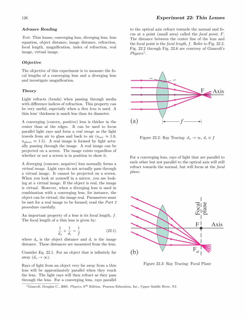
Rays of light from an object very far away from a thinlens will be approximately parallel when they reachthe lens. The light rays will then refract as they passthrough the lens. For a converging lens, rays parallel
to the optical axis refract towards the normal and fo-cus at a point (small area) called the focal point, F .The distance between the center line of the lens andthe focal point is the focal length, f . Refer to Fig. 22.2.Fig. 22.2 through Fig. 22.6 are courtesy of Giancoli’sPhysics1.
Figure 22.2: Ray Tracing: do
! 1, di
⌘ f
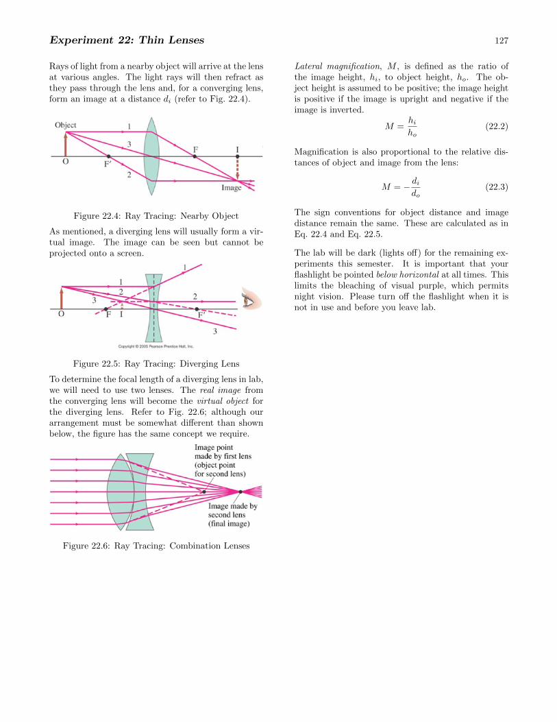
For a converging lens, rays of light that are parallel toeach other but not parallel to the optical axis will stillrefract towards the normal, but will focus at the focalplane.
Figure 22.3: Ray Tracing: Focal Plane
1Giancoli, Douglas C., 2005. Physics, 6th Edition. Pearson Education, Inc., Upper Saddle River, NJ.
Experiment 22: Thin Lenses 127
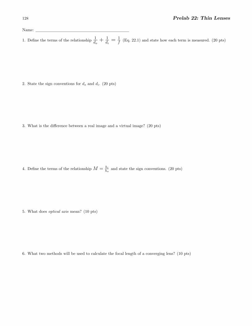
Rays of light from a nearby object will arrive at the lensat various angles. The light rays will then refract asthey pass through the lens and, for a converging lens,form an image at a distance d
i
(refer to Fig. 22.4).
Figure 22.4: Ray Tracing: Nearby Object
As mentioned, a diverging lens will usually form a vir-tual image. The image can be seen but cannot beprojected onto a screen.
Figure 22.5: Ray Tracing: Diverging Lens
To determine the focal length of a diverging lens in lab,we will need to use two lenses. The real image fromthe converging lens will become the virtual object forthe diverging lens. Refer to Fig. 22.6; although ourarrangement must be somewhat di↵erent than shownbelow, the figure has the same concept we require.
Figure 22.6: Ray Tracing: Combination Lenses
Lateral magnification, M , is defined as the ratio ofthe image height, h
i
, to object height, ho
. The ob-ject height is assumed to be positive; the image heightis positive if the image is upright and negative if theimage is inverted.
M =hi
ho
(22.2)
Magnification is also proportional to the relative dis-tances of object and image from the lens:
M = � di
do
(22.3)
The sign conventions for object distance and imagedistance remain the same. These are calculated as inEq. 22.4 and Eq. 22.5.
The lab will be dark (lights o↵) for the remaining ex-periments this semester. It is important that yourflashlight be pointed below horizontal at all times. Thislimits the bleaching of visual purple, which permitsnight vision. Please turn o↵ the flashlight when it isnot in use and before you leave lab.
128 Prelab 22: Thin Lenses
Name:
1. Define the terms of the relationship1do
+ 1di
= 1f (Eq. 22.1) and state how each term is measured. (20 pts)
2. State the sign conventions for do
and di
. (20 pts)
3. What is the di↵erence between a real image and a virtual image? (20 pts)
4. Define the terms of the relationship M = h
i
h
o
and state the sign conventions. (20 pts)
5. What does optical axis mean? (10 pts)
6. What two methods will be used to calculate the focal length of a converging lens? (10 pts)
Experiment 22: Thin Lenses 129
PROCEDURE
PART 1: Converging Lens
Method I - Use the lens equation (Eq. 22.1)
1. Refer to Fig. 22.1. Mount the lens, screen, and lightsource on the optical bench. Adjust the height ofthe object, lens(es), and screen so that the opticalaxis passes through the center of each element.
2. Adjust the position of the lens and the screen un-til a clear image of the object is projected onto thescreen. Considering Eq. 22.1, how many combina-tions of d
i
and do
are possible?
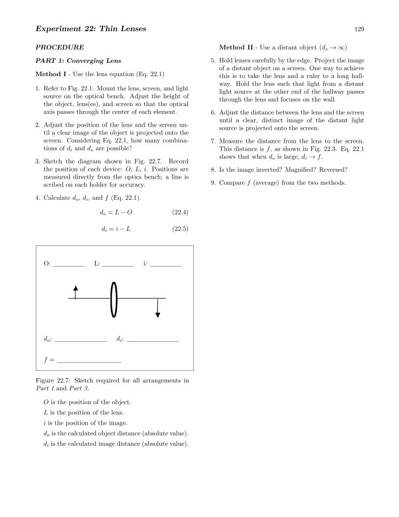
3. Sketch the diagram shown in Fig. 22.7. Recordthe position of each device: O, L, i. Positions aremeasured directly from the optics bench; a line isscribed on each holder for accuracy.
4. Calculate do
, di
, and f (Eq. 22.1).
do
= L�O (22.4)
di
= i� L (22.5)
O: L: i:
do
: di
:
f =
Figure 22.7: Sketch required for all arrangements inPart 1 and Part 3.
O is the position of the object.
L is the position of the lens.
i is the position of the image.
do
is the calculated object distance (absolute value).
di
is the calculated image distance (absolute value).
Method II - Use a distant object (do
! 1)
5. Hold lenses carefully by the edge. Project the imageof a distant object on a screen. One way to achievethis is to take the lens and a ruler to a long hall-way. Hold the lens such that light from a distantlight source at the other end of the hallway passesthrough the lens and focuses on the wall.
6. Adjust the distance between the lens and the screenuntil a clear, distinct image of the distant lightsource is projected onto the screen.
7. Measure the distance from the lens to the screen.This distance is f , as shown in Fig. 22.3. Eq. 22.1shows that when d
o
is large, di
! f .
8. Is the image inverted? Magnified? Reversed?
9. Compare f (average) from the two methods.
130 Experiment 22: Thin Lenses
PART 2: Diverging Lens
To determine the focal length of a diverging lens,the lens must create a measurable, real image as inPart 1. However, light cannot be focused througha diverging lens to form a real image unless thatlight was already converging. To accomplish this, areal image from a converging lens will be used as avirtual object.2
10. Form a real image using a converging lens. Note:do
should be greater than 2f .
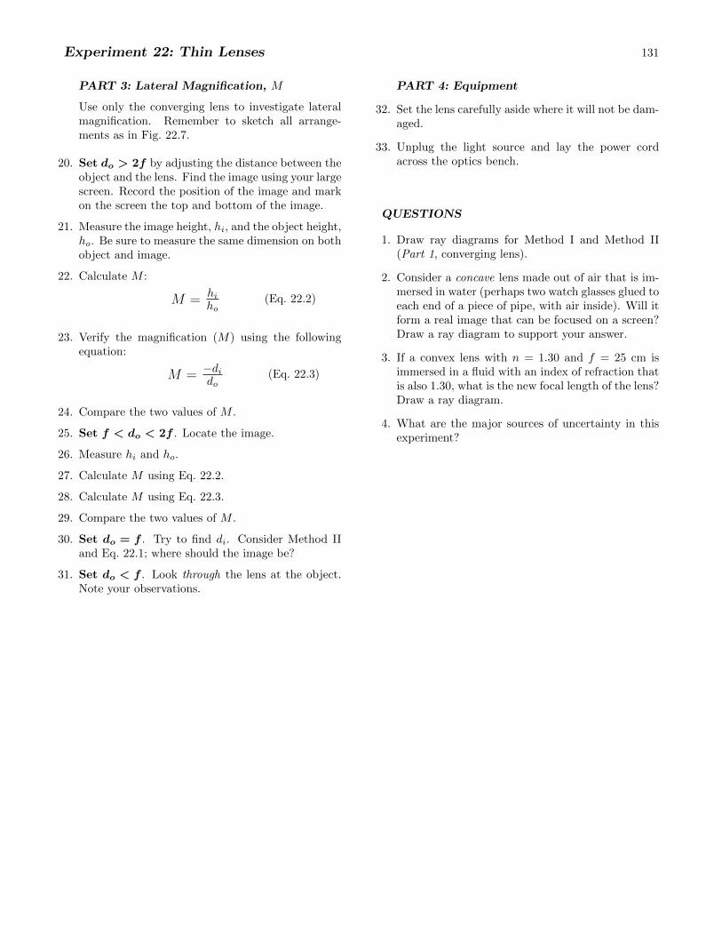
11. Begin your required sketch (Fig. 22.9).
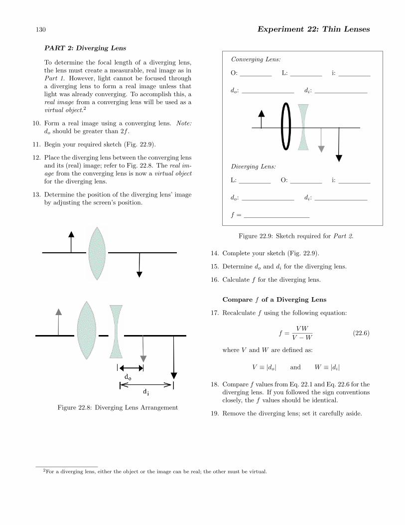
12. Place the diverging lens between the converging lensand its (real) image; refer to Fig. 22.8. The real im-age from the converging lens is now a virtual objectfor the diverging lens.
13. Determine the position of the diverging lens’ imageby adjusting the screen’s position.
Figure 22.8: Diverging Lens Arrangement
Converging Lens:
O: L: i:
do
: di
:
Diverging Lens:
L: O: i:
do
: di
:
f =
Figure 22.9: Sketch required for Part 2.
14. Complete your sketch (Fig. 22.9).
15. Determine do
and di
for the diverging lens.
16. Calculate f for the diverging lens.
Compare f of a Diverging Lens
17. Recalculate f using the following equation:
f =VW
V �W(22.6)
where V and W are defined as:
V ⌘ |do
| and W ⌘ |di
|
18. Compare f values from Eq. 22.1 and Eq. 22.6 for thediverging lens. If you followed the sign conventionsclosely, the f values should be identical.
19. Remove the diverging lens; set it carefully aside.
2For a diverging lens, either the object or the image can be real; the other must be virtual.
Experiment 22: Thin Lenses 131
PART 3: Lateral Magnification, M
Use only the converging lens to investigate lateralmagnification. Remember to sketch all arrange-ments as in Fig. 22.7.
20. Set do
> 2f by adjusting the distance between theobject and the lens. Find the image using your largescreen. Record the position of the image and markon the screen the top and bottom of the image.
21. Measure the image height, hi
, and the object height,ho
. Be sure to measure the same dimension on bothobject and image.
22. Calculate M :
M = hi
ho
(Eq. 22.2)
23. Verify the magnification (M) using the followingequation:
M = �di
do
(Eq. 22.3)
24. Compare the two values of M .
25. Set f < do
< 2f . Locate the image.
26. Measure hi
and ho
.
27. Calculate M using Eq. 22.2.
28. Calculate M using Eq. 22.3.
29. Compare the two values of M .
30. Set do
= f . Try to find di
. Consider Method IIand Eq. 22.1; where should the image be?
31. Set do
< f . Look through the lens at the object.Note your observations.
PART 4: Equipment
32. Set the lens carefully aside where it will not be dam-aged.
33. Unplug the light source and lay the power cordacross the optics bench.
QUESTIONS
1. Draw ray diagrams for Method I and Method II(Part 1, converging lens).
2. Consider a concave lens made out of air that is im-mersed in water (perhaps two watch glasses glued toeach end of a piece of pipe, with air inside). Will itform a real image that can be focused on a screen?Draw a ray diagram to support your answer.
3. If a convex lens with n = 1.30 and f = 25 cm isimmersed in a fluid with an index of refraction thatis also 1.30, what is the new focal length of the lens?Draw a ray diagram.
4. What are the major sources of uncertainty in thisexperiment?
Related Documents