Department of Mechanical Engineering Page 1 WCTM Gurgaon EXPERIMENT 1 Aim: Study and Practice of Orthogonal & Oblique Cutting on a Lathe. Apparatus: Lathe Machine Theory: It appears from the diagram in the following figure that while turning ductile material by a sharp tool, the continuous chip would flow over the tool’s rake surface and in the direction apparently perpendicular to the principal cutting edge, i.e., along orthogonal plane which is normal to the cutting plane containing the principal cutting edge. But practically, the chip may not flow along the orthogonal plane for several factors like presence of inclination angle λ, etc. The role of inclination angle λ on the direction of chip flow is schematically shown in figure which visualizes that, • when λ=0, the chip flows along orthogonal plane, i.e., ρ = 0 • when λ≠0, the chip flow is deviated from π and ρ = λ where ρ is chip flow deviation (from π ) angle

Welcome message from author
This document is posted to help you gain knowledge. Please leave a comment to let me know what you think about it! Share it to your friends and learn new things together.
Transcript

Department of Mechanical Engineering Page 1 WCTM Gurgaon
EXPERIMENT 1
Aim: Study and Practice of Orthogonal & Oblique Cutting on a Lathe.
Apparatus: Lathe Machine
Theory:
It appears from the diagram in the following figure that while turning ductile material by
a sharp tool, the continuous chip would flow over the tool’s rake surface and in the direction
apparently perpendicular to the principal cutting edge, i.e., along orthogonal plane which is
normal to the cutting plane containing the principal cutting edge. But practically, the chip may
not flow along the orthogonal plane for several factors like presence of inclination angle λ, etc.
The role of inclination angle λ on the direction of chip flow is schematically shown in figure
which visualizes that,
• when λ=0, the chip flows along orthogonal plane, i.e., ρ = 0
• when λ≠0, the chip flow is deviated from π and ρ = λ where ρ is chip flow deviation (from π )
angle

Department of Mechanical Engineering Page 2 WCTM Gurgaon
Orthogonal cutting: when chip flows along orthogonal plane, π, i.e., ρ = 0
In Orthogonal cutting
1- Cutting tool travel in the direction perpendicular to the cutting edge.
2- The cutting edge clear either end of work piece.
3- Chip flows in the direction perpendicular to the cutting edge.
4- Two mutually perpendicular cutting forces act on the work piece.
Oblique cutting: when chip flow deviates from orthogonal plane, i.e. ρ ≠0 But practically ρ may
be zero even if λ= 0 and ρ may not be exactly equal to λ even if λ≠0. Because there are some
other (than λ) factors also which may cause chip flow deviation.
In Oblique cutting
1- Cutting edge travels, making an angle with the normal of cutting edge.
2- The cutting edge may or may not clear either end of work piece.
3- Chip flows, making an angle with normal of cutting edge.
4- Three mutually perpendicular forces are involved.
Result: Hence the study of Orthogonal & Oblique Cutting on a Lathe is completed.

Department of Mechanical Engineering Page 3 WCTM Gurgaon
EXPERIMENT 2
Aim: Machining time calculation and comparison with actual machining time while cylindrical
turning on a Lathe and finding out cutting efficiency.
Apparatus: Lathe Machine
Theory:
The major aim and objectives in machining industries generally are;
• reduction of total manufacturing time, T
• increase in MRR, i.e., productivity
• reduction in machining cost without sacrificing product quality
• increase in profit or profit rate, i.e., profitability.
Hence, it becomes extremely necessary to determine the actual machining time TC required to
produce a job mainly for,
• assessment of productivity
• evaluation of machining cost
• measurement of labour cost component assessment of relative performance or capability of any
machine tool, cutting tool, cutting fluid or any special or new techniques in terms of saving in
machining time.
The machining time, TC required for a particular operation can be determined roughly by
calculation i.e., estimation οr precisely, if required, by measurement. Measurement definitely
gives more accurate result and in detail but is tedious and expensive. Whereas, estimation by
simple calculations though may not be that accurate, is simple, quick and inexpensive. Hence,
determination of machining time, specially by simple calculations using suitable equations is
essentially done regularly for various purposes.
Procedure:
The factors that govern machining time will be understood from a simple case of machining.
A steel rod has to be reduced in diameter from D1 to D2 over a length L by straight turning in
a centre lathe as indicated in Fig.

Department of Mechanical Engineering Page 4 WCTM Gurgaon

Department of Mechanical Engineering Page 5 WCTM Gurgaon
Calculations:-
S.N. L A O Lc Vc D N So D1 D2 T nP Tc
Where,
L= length of the work piece in mm;
A= approach run in mm;
O= over run in mm;
Lc=actual length of cut in mm;
Vc= cutting velocity in mm/min;
D= diameter of the job before cut in mm;
N=spindle speed in rpm;
So= tool feed in mm/rev;
D1= initial diameter before passes in mm;
D2=final diameter after passes in mm;
t=depth of cut in one pass in mm;
nP =no of passes;
Tc=machining time in min;
Result: The machining time of the turning operation is done and compared.
Department of Mechanical Engineering Page 6 WCTM Gurgaon
EXPERIMENT 3
Aim: To study the Tool Life while Milling a component on the Milling Machine.
Apparatus: Milling Machine
Theory:
Tool life: Time of cutting during two successive milling or indexing of the tool. Tool life is the
length of cutting time that a tool can be used or a certain flank wear value has occurred (0.02”).
Tool life criteria in production
1. Complete failure of the cutting edge;
2. Chips becomes ribbony, stingy, and difficult to dispose of;
3. Degradation of the surface finish on the work;
4. Cumulative cutting time or workpiece count.
Taylor’s tool life equation:
VTn = C
V = cutting speed
n = cutting exponent
C = cutting constant
T = tool life
n and C depend on speed, work material, tool material, etc.
Cutting Speed can be obtained by the formula as shown:
N= (V*1000) / (π*d)
Where :
N=spindle speed in rpm;
V=cutting speed in m/min;
d=diameter of cutter in mm;
Procedure:
1. Determine the cutting speed by using given d and N values.
2. Apply Taylor’s equation and the n and C values, we can solve for tool life.

Department of Mechanical Engineering Page 7 WCTM Gurgaon
Calculations:-
S.N. n C d N V T
Result: Thus the tool life of milling cutter is found out.

Department of Mechanical Engineering Page 8 WCTM Gurgaon
EXPERIMENT 4
Aim: To study Tool wear of a cutting tool while Drilling on a Drilling Machine.
Apparatus: Drilling Machine
Theory:
Tool wears are classified as shown below

Department of Mechanical Engineering Page 9 WCTM Gurgaon
Crater wear:
Consists of a concave section on the tool face formed by the action of the chip sliding on the
surface. Crater wear affects the mechanics of the process increasing the actual rake angle of the
cutting tool and consequently, making cutting easier. At the same time, the crater wear weakens
the tool wedge and increases the possibility for tool breakage. In general, crater wear is of a
relatively small concern.
Flank wear:
Occurs on the tool flank as a result of friction between the machined surface of the work piece
and the tool flank. Flank wear appears in the form of so-called wear land and is measured by
the width of this wear land, VB, Flank wear affects to the great extend the mechanics of cutting.
Cutting forces increase significantly with flank wear. If the amount of flank wear exceeds some
critical value (VB > 0.5~0.6 mm), the excessive cutting force may cause tool failure.
Catastrophic wear (Built up Edge):
In single point cutting of metals, a built up edge (BUE) is an accumulation of material against
the rake face that seizes to the tool tip, separating it from the chip. The built up edge effectively
changes tool geometry and rake steepness. It also reduces the contact area between the chip and the
cutting tool, leading to:
A reduction in the power demand of the cutting operation.
Slight increase in tool life, since the cutting is partly being done by the built up edge
rather than the tool itself.
Abrasion wear: this is a mechanical wearing action due to hard particles in the work material
gouging and removing small portions of the tool.
Location: both on rake and flank faces.
Adhesion wear: as the cutting chip flows across the tool under high temperature and high
pressure, small particles of the tool are "welded" to the chip surface and taken away.

Department of Mechanical Engineering Page 10 WCTM Gurgaon
Location: mostly on the rake face.
Diffusion wear: is a process in which an exchange of atoms takes place across a close contact at
the tool-chip boundary between two materials.
Location: on the rake face.

Department of Mechanical Engineering Page 11 WCTM Gurgaon
EXPERIMENT 5
Aim: To study the Speed, Feed, Tool, Preparatory (Geometric) and miscellaneous functions for
NC part programming
Apparatus: NC Milling Machine
Theory:
Part program: A computer program to specify
- Which tool should be loaded on the machine spindle?
- What are the cutting conditions (speed, feed, coolant ON/OFF etc.)
- The start point and end point of a motion segment
- How to move the tool with respect to the machine.
CNC G-codes: Preparatory Functions– involve actual tool moves.
G00 - Positioning at rapid speed; Mill and Lathe
G01 - Linear interpolation (machining a straight line); Mill and Lathe
G02 - Circular interpolation clockwise (machining arcs); Mill and Lathe
G03 - Circular interpolation, counter clockwise; Mill and Lathe
G04 - Mill and Lathe, Dwell
G09 - Mill and Lathe, Exact stop
G10 - Setting offsets in the program; Mill and Lathe
G12 - Circular pocket milling, clockwise; Mill
G13 - Circular pocket milling, counterclockwise; Mill
G17 - X-Y plane for arc machining; Mill and Lathe with live tooling
G18 - Z-X plane for arc machining; Mill and Lathe with live tooling
G19 - Z-Y plane for arc machining; Mill and Lathe with live tooling
G20 - Inch units; Mill and Lathe
G21 - Metric units; Mill and Lathe
G27 - Reference return check; Mill and Lathe
G28 - Automatic return through reference point; Mill and Lathe
G29 - Move to location through reference point; Mill and Lathe (slightly different for each
machine)
G31 - Skip function; Mill and Lathe
G32 - Thread cutting; Lathe
G33 - Thread cutting; Mill
G40 - Cancel diameter offset; Mill. Cancel tool nose offset; Lathe
G41 - Cutter compensation left; Mill. Tool nose radius compensation left; Lathe
G42 - Cutter compensation right; Mill. Tool nose radius compensation right; Lathe
G43 - Tool length compensation; Mill
G44 - Tool length compensation cancel; Mill (sometimes G49)
G50 - Set coordinate system and maximum RPM; Lathe
G52 - Local coordinate system setting; Mill and Lathe
G53 - Machine coordinate system setting; Mill and Lathe
G54~G59 - Work piece coordinate system settings #1 t0 #6; Mill and Lathe
Department of Mechanical Engineering Page 12 WCTM Gurgaon
G61 - Exact stop check; Mill and Lathe
G65 - Custom macro call; Mill and Lathe
G70 - Finish cycle; Lathe
G71 - Rough turning cycle; Lathe
G72 - Rough facing cycle; Lathe
G73 - Irregular rough turning cycle; Lathe
G73 - Chip break drilling cycle; Mill
G74 - Left hand tapping; Mill
G74 - Face grooving or chip break drilling; Lathe
G75 - OD groove pecking; Lathe
G76 - Fine boring cycle; Mill
G76 - Threading cycle; Lathe
G80 - Cancel cycles; Mill and Lathe
G81 - Drill cycle; Mill and Lathe
G82 - Drill cycle with dwell; Mill
G83 - Peck drilling cycle; Mill
G84 - Tapping cycle; Mill and Lathe
G85 - Bore in, bore out; Mill and Lathe
G86 - Bore in, rapid out; Mill and Lathe
G87 - Back boring cycle; Mill
G90 - Absolute programming
G91 - Incremental programming
G92 - Reposition origin point; Mill
G92 - Thread cutting cycle; Lathe
G94 - Per minute feed; Mill
G95 - Per revolution feed; Mill
G96 - Constant surface speed control; Lathe
G97 - Constant surface speed cancel
G98 - Per minute feed; Lathe
G99 - Per revolution feed; Lathe
CNC M Codes: Miscellaneous Functions – involve actions necessary for machining (i.e. spindle
on/off, coolant on/off).
M00 - Program stop; Mill and Lathe
M01 - Optional program stop; Lathe and Mill
M02 - Program end; Lathe and Mill
M03 - Spindle on clockwise; Lathe and Mill
M04 - Spindle on counterclockwise; Lathe and Mill
M05 - Spindle off; Lathe and Mill
M06 - Tool change; Mill
M08 - Coolant on; Lathe and Mill
M09 - Coolant off; Lathe and Mill
M10 - Chuck or rotary table clamp; Lathe and Mill
M11 - Chuck or rotary table clamp off; Lathe and Mill
M19 - Orient spindle; Lathe and Mill
Department of Mechanical Engineering Page 13 WCTM Gurgaon
M30 - Program end, return to start; Lathe and Mill
M97 - Local sub-routine call; Lathe and Mill
M98 - Sub-program call; Lathe and Mill
M99 - End of sub program; Lathe and Mill
CNC N Codes: Gives an identifying number for each block of information.
X, Y, and Z codes are used to specify the coordinate axis.
• Number following the code defines the coordinate at the end of the move relative to an
incremental or absolute reference point.
• The number may require that a specific format be used (i.e. 3.4 means three numbers before the
decimal and four numbers after the decimal).
I, J, and K codes are used to specify the coordinate axis when defining the center of a circle.
• Number following the code defines the respective coordinate for the center of the circle.
• The number may require that a specific format be used (i.e. 3.4 means three numbers before
the decimal and four numbers after the decimal).
F-code: used to specify the feed rate
S-code: used to specify the spindle speed
T-code: used to specify the tool identification number associated with the tool to be used in
subsequent operations.
R-code:
•Retract distance when used with G81, 82, and 83.
•Radius when used with G02 and G03.
P-code: Used to specify the dwell time associated with G04.

Department of Mechanical Engineering Page 14 WCTM Gurgaon
EXPERIMENT 6
Aim: To study the part programming on a NC Milling Machine for a Rectangular Slot.
Apparatus: NC Milling Machine
Procedure:
N01 G90 EOB
N02 G17 EOB
N03 M06 EOB
N04 M04 S1200
N05 G01 X27.5 Y-7.5 F30 EOB
N06 G01 Z-5.6 EOB
N07 L601 EOB
N08 Z-6.3 EOB
N09 L601 EOB N140 M17 EOB
N010 Z-7.0 EOB
N011 L601 EOB
N012 Z5 EOB

Department of Mechanical Engineering Page 15 WCTM Gurgaon
N013 GO X0 Y0 EOB
N014 M05 EOB
N015 M30 EOB

Department of Mechanical Engineering Page 16 WCTM Gurgaon
EXPERIMENT 7
AIM: To study the Part Programming and Proving on a NC Milling Machine:- a. Point to Point Programming
b. Absolute Programming
c. Incremental Programming
Apparatus: NC Milling Machine
Procedure:
Point to Point Programming
In point to point system, the machining is done at specific positions. The working-piece remains
unaffected as the tool moves from one position to the next. The system is the simplest. In fig.1,
after drilling the hole at position A, the tool moves to position B, along the dotted line. A drilling
machine is the best example of point to point system.
Figure-1
CNC Absolute Programming G90 Example Code
With absolute positioning, we tell the machine where to move based on a common point, called
X0 Y0 and Z0. Every time we need to move to a certain position, the ending point of that move
is in direct relationship to this “common point”.
This CNC example code illustrates the usage of CNC Absolute Programming G90 G-Code and
Incremental Programming G91 G-Code, as well as the usage of Circular Interpolation G-Code
(G02/G03).

Department of Mechanical Engineering Page 17 WCTM Gurgaon
CNC Mill Programming Absolute Incremental G90 G91 Example Code
Mill Circular Interpolation G02 G03 with R
G92 X200 Y40 Z0
G90 G03 X140 Y100 R60 F300
G02 X120 Y60 R50
Mill Circular Interpolation G02 G03 with I
G92 X200 Y40 Z0
G90 G03 X140 Y100 I-60 F300
G02 X120 Y60 I-50
CNC Incremental Programming G91 Example Code
With incremental positioning, we are telling the machine where to go in relationship to where it
currently is at. Basically like a set of directions given from where the machine stopped last.
Mill Circular Interpolation G02 G03 with R
G91 G03 X-60 Y60 R60 F300
G02 X-20 Y-40 R50
Mill Circular Interpolation G02 G03 with I
G91 G03 X-60 Y60 I-60 F300
G02 X-20 Y-40 I-50

Department of Mechanical Engineering Page 18 WCTM Gurgaon
EXPERIMENT 8
AIM: To study the construction and operation of a shaping machine.
REQUIREMENTS:
1. Shaping Machine.
PARTS:
Important parts of the machine are:
1. Frame (Machine Column)
2. Ram
3. Machine Table with table support
4. Saddle
5. Ram Head with Tool Slide and Tool Post with Clapper Box Block
6. Main Gearing (Gear Train and oscillating slider crank mechanism)
7. Drive (Electro Motor)
Department of Mechanical Engineering Page 19 WCTM Gurgaon
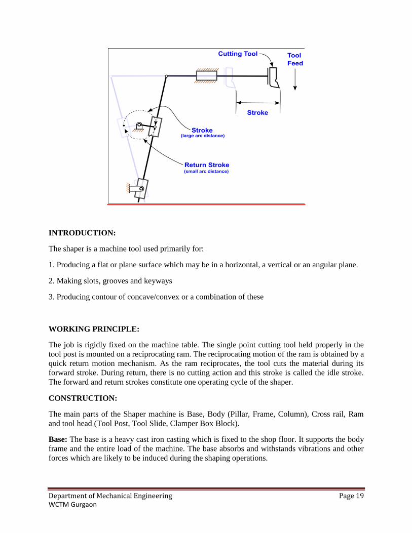
INTRODUCTION:
The shaper is a machine tool used primarily for:
1. Producing a flat or plane surface which may be in a horizontal, a vertical or an angular plane.
2. Making slots, grooves and keyways
3. Producing contour of concave/convex or a combination of these
WORKING PRINCIPLE:
The job is rigidly fixed on the machine table. The single point cutting tool held properly in the
tool post is mounted on a reciprocating ram. The reciprocating motion of the ram is obtained by a
quick return motion mechanism. As the ram reciprocates, the tool cuts the material during its
forward stroke. During return, there is no cutting action and this stroke is called the idle stroke.
The forward and return strokes constitute one operating cycle of the shaper.
CONSTRUCTION:
The main parts of the Shaper machine is Base, Body (Pillar, Frame, Column), Cross rail, Ram
and tool head (Tool Post, Tool Slide, Clamper Box Block).
Base: The base is a heavy cast iron casting which is fixed to the shop floor. It supports the body
frame and the entire load of the machine. The base absorbs and withstands vibrations and other
forces which are likely to be induced during the shaping operations.

Department of Mechanical Engineering Page 20 WCTM Gurgaon
Body (Pillar, Frame, Column): It is mounted on the base and houses the drive mechanism
compressing the main drives, the gear box and the quick return mechanism for the ram
movement. The top of the body provides guide ways for the ram and its front provides the guide
ways for the cross rail.
PRINCIPLE OF PRODUCING FLAT SURFACE IN SHAPING MACHINE:
Cross rail: The cross rail is mounted on the front of the body frame and can be moved up and
down. The vertical movement of the cross rail permits jobs of different heights to be
accommodated below the tool. Sliding along the cross rail is a saddle which carries the work
table.
Ram and tool head: The ram is driven back and forth in its slides by the slotted link
mechanism. The back and forth movement of ram is called stroke and it can be adjusted
according to the length of the work piece to be-machined.
OPERATIONS:
Shaping is a technique with straight-lined motion (cutting and feed motion).
The feed motion takes place in steps.
The work piece clamping fixture (compound slide) consists of saddle and machine table.
The machine table is additionally supported.
The ram carries the ram head consisting of swivel-head plate, tool slide, clapper box with tool
block and tool holder (tool post).
During the working stroke the tool block rests on the clapper box (as a result of the cutting
pressure), during the return stroke it is lifted. In this way the tool tip is protected. With older
shaping machines the tool is dragging over the work-piece during the return stroke. The working
position is reached by the dead weight and, thus, by falling back.
Modern machines have an automatic tool lifter. For shaping oblique surfaces the tool slide can be
swiveled on the swivel-head plate. In order to maintain the mobility of the tool block, it is also
possible to set the clapper box on the tool slide at an angle, i.e. to swivel it in the circular slot.
Related Documents


![s3images.coroflot.com · F&A, Gurgaon B. Process, Gurgaon Harish Kumar C&S, Gurgaon f Gaurav Verma IT, Gurgaon Sumit Bhushan IT, Gurgaon Ankur Gupta C&S, Gurgaon . JD ]/lcthur Chief](https://static.cupdf.com/doc/110x72/6016a040010c7418cb5d91b4/fa-gurgaon-b-process-gurgaon-harish-kumar-cs-gurgaon-f-gaurav-verma.jpg)

