Experience in developing and testing network protocol software using FDTs M. U ¨ mit Uyar a, * , Mariusz A. Fecko b , Ali Y. Duale c , Paul D. Amer d , Adarshpal S. Sethi d a Department of Electrical Engineering, The City College of the City University of New York, 140th street at Convent Avenue, NY 10031, USA b Applied Research Area, Telcordia Technologies, Inc., Morristown, NJ, USA c System Architecture Compliance, IBM, Poughkeepsie, NY, USA d Department of Computer and Information Sciences, University of Delaware, Newark, DE, USA Abstract This paper presents the research effort to formally specify, develop and test a complex real-life protocol for mobile network radios (MIL- STD 188-220). As a result, the team of researchers from the University of Delaware and the City College of the City University of New York, collaborating with scientists from CECOM (an R&D facility of the US Army) and the US Army Research Laboratory, have helped advance the state-of-the-art in the design, development, and testing of wireless communications protocols. Estelle is used both as the formal specification language for MIL-STD 188-220 and the source to automatically generate conformance test sequences. The formal test generation effort identified several theoretical problems for wireless communication protocols (possibly applicable to network protocols in general): (1) the timing constraint problem, (2) the controllability problem, (3) inconsistency detection and elimination problem and (4) the conflicting timers problem. Based on the collaborative research results, two software packages were written to generate conformance test sequences for MIL-STD 188-220. These packages helped generate tests for MIL-STD 188-220’s Data Link Types 1 and 4 services that were realizable without timer interruptions while providing a 200% increase in test coverage. The test cases have been delivered and are being used by a CECOM conformance testing facility. q 2003 Elsevier B.V. All rights reserved. Keywords: Conformance testing; Estelle; Formal description technique; Formal specification; MIL-STD 188-220; Protocol specification; Test case generation; PACS 1. Introduction Complexity of the wireless protocols used in MIL-STD 188-220, being developed for mobile combat network radios [23], necessitated that a formal approach be taken in protocol specification, development and testing. Estelle [40] was chosen as the formal specification language to define the protocols in MIL-STD 188-220, from which the conformance tests were automatically generated. Let us first provide the following data to help the reader realize the magnitude of size and complexity of the wireless protocols used in 188-220. The Datalink and Network layer specifications consist of 69 and 19 documents, respectively, describing the architecture, interfaces, EFSM, and state table of each module. The Datalink layer specification is accompanied by three Estelle source code files (for Datalink classes A, B, and C) with approximately 1600, 8700, and 2400 lines of code, respectively. The Estelle source code for the Network layer has 7150 lines of code, defining 34 states and 370 transitions in seven EFSMs [88]. Automatic test generation from Estelle specifications presented various theoretical problems defined as follows: † Timing constraint problem [79]. During testing, if active timers were not taken into account when the tests were generated, these timers can disrupt the test sequences, thereby failing correct implementations or worse, passing incorrect ones. For accurate testing, timers must be incorporated as constraints into the extended FSM (EFSM) model of an Estelle specification. † Controllability problem [12,32,33]. Test sequence gen- eration is limited by the controllability of an Implemen- tation Under Test (IUT) [8]. Testers may not have direct access to all interface(s) in which the IUT accepts inputs. Typically, the interfaces with upper layers (or with timers) are difficult or impossible to access during real testing conditions. In this case, some inputs cannot be 0950-5849/03/$ - see front matter q 2003 Elsevier B.V. All rights reserved. doi:10.1016/S0950-5849(03)00062-4 Information and Software Technology 45 (2003) 815–835 www.elsevier.com/locate/infsof * Corresponding author. Tel.: þ 1-212-650-5632; fax: þ1-212-650-8249. E-mail address: [email protected] (M. U ¨ . Uyar).

Welcome message from author
This document is posted to help you gain knowledge. Please leave a comment to let me know what you think about it! Share it to your friends and learn new things together.
Transcript
Experience in developing and testing network protocol
software using FDTs
M. Umit Uyara,*, Mariusz A. Feckob, Ali Y. Dualec, Paul D. Amerd, Adarshpal S. Sethid
aDepartment of Electrical Engineering, The City College of the City University of New York, 140th street at Convent Avenue, NY 10031, USAbApplied Research Area, Telcordia Technologies, Inc., Morristown, NJ, USA
cSystem Architecture Compliance, IBM, Poughkeepsie, NY, USAdDepartment of Computer and Information Sciences, University of Delaware, Newark, DE, USA
Abstract
This paper presents the research effort to formally specify, develop and test a complex real-life protocol for mobile network radios (MIL-
STD 188-220). As a result, the team of researchers from the University of Delaware and the City College of the City University of New York,
collaborating with scientists from CECOM (an R&D facility of the US Army) and the US Army Research Laboratory, have helped advance
the state-of-the-art in the design, development, and testing of wireless communications protocols. Estelle is used both as the formal
specification language for MIL-STD 188-220 and the source to automatically generate conformance test sequences. The formal test
generation effort identified several theoretical problems for wireless communication protocols (possibly applicable to network protocols in
general): (1) the timing constraint problem, (2) the controllability problem, (3) inconsistency detection and elimination problem and (4) the
conflicting timers problem. Based on the collaborative research results, two software packages were written to generate conformance test
sequences for MIL-STD 188-220. These packages helped generate tests for MIL-STD 188-220’s Data Link Types 1 and 4 services that were
realizable without timer interruptions while providing a 200% increase in test coverage. The test cases have been delivered and are being
used by a CECOM conformance testing facility.
q 2003 Elsevier B.V. All rights reserved.
Keywords: Conformance testing; Estelle; Formal description technique; Formal specification; MIL-STD 188-220; Protocol specification; Test case generation;
PACS
1. Introduction
Complexity of the wireless protocols used in MIL-STD
188-220, being developed for mobile combat network
radios [23], necessitated that a formal approach be taken
in protocol specification, development and testing. Estelle
[40] was chosen as the formal specification language to
define the protocols in MIL-STD 188-220, from which the
conformance tests were automatically generated.
Let us first provide the following data to help the reader
realize the magnitude of size and complexity of the wireless
protocols used in 188-220. The Datalink and Network layer
specifications consist of 69 and 19 documents, respectively,
describing the architecture, interfaces, EFSM, and state
table of each module. The Datalink layer specification is
accompanied by three Estelle source code files (for Datalink
classes A, B, and C) with approximately 1600, 8700, and
2400 lines of code, respectively. The Estelle source code for
the Network layer has 7150 lines of code, defining 34 states
and 370 transitions in seven EFSMs [88].
Automatic test generation from Estelle specifications
presented various theoretical problems defined as follows:
† Timing constraint problem [79]. During testing, if active
timers were not taken into account when the tests were
generated, these timers can disrupt the test sequences,
thereby failing correct implementations or worse,
passing incorrect ones. For accurate testing, timers
must be incorporated as constraints into the extended
FSM (EFSM) model of an Estelle specification.
† Controllability problem [12,32,33]. Test sequence gen-
eration is limited by the controllability of an Implemen-
tation Under Test (IUT) [8]. Testers may not have direct
access to all interface(s) in which the IUT accepts inputs.
Typically, the interfaces with upper layers (or with
timers) are difficult or impossible to access during real
testing conditions. In this case, some inputs cannot be
0950-5849/03/$ - see front matter q 2003 Elsevier B.V. All rights reserved.
doi:10.1016/S0950-5849(03)00062-4
Information and Software Technology 45 (2003) 815–835
www.elsevier.com/locate/infsof
* Corresponding author. Tel.: þ1-212-650-5632; fax: þ1-212-650-8249.
E-mail address: [email protected] (M. U. Uyar).
directly applied; the interactions involving such inter-
faces may render some portions of the protocol
untestable, and may introduce non-determinism and/or
race conditions during testing.
† Inconsistency detection and elimination problem [25,26].
Infeasible test sequences may be generated unless
possible conflicts among the protocol’s variables used
in the actions and the conditions are avoided.
† Conflicting timers problem [34]. Infeasible test
sequences may result from a protocol’s variables
modeling multiple timers that may be running
simultaneously.
The team of researchers and scientists that participated in
this research and development effort are from the University
of Delaware (UD), the City College of the City University
of New York (CCNY), the Army Research Laboratory
(ARL), US Army Communications-Electronics Command
(CECOM), and the Joint Combat Net Radio Working Group
(CNR-WG). As a result of the collaboration, the synergistic
framework to develop C4I (Command, Control, Communi-
cations, Computers, and Intelligence) systems with the help
of formal methods serves as a model for future US
Department of Defense networking standards development
[27].
Based on the solutions to these theoretical problems, two
software packages, called efsm2fsm-rcpt, and (2) INDEEL,
have been developed to automatically generate test cases
from the EFSM models of Estelle specifications. The sizes
of the resulting FSMs derived from the Estelle specifications
range from 48 to 303 states, and from 119 to 925 transitions.
The corresponding test sequences range from 145 to 2803
test steps. These tests are free of interruptions due to
unexpected timeouts while their coverage of the number of
testable transitions increased from approximately 200 to
over 700 by utilizing multiple interfaces without controll-
ability conflicts.
Section 2 describes the general approach and the research
results for test generation from Estelle specifications at UD
and CCNY. Section 3 presents efsm2fsm-rcpt and INDEEL
software systems. Section 4 summarizes our technology
transfer from the UD and CCNY with the CECOM. Finally,
Section 5 presents the authors’ personal perspective on how
the protocol development process was improved thanks to
using formal methods. A brief introduction of MIL-STD
188-220 is provided in Appendix A.
2. Test case generation
Formal methods in communications protocol specifica-
tion and conformance testing have been widely used in the
design and testing of real-life protocols [5,7,20,21,35,43,44,
46,59,90]. In particular, the Estelle formal description
technique (FDT) [13,40,67,70] has been used on several
occasions to resolve ambiguities within protocols used
world-wide [9,18,42,57,68,83].
A number of techniques have been proposed to generate
test sequences from Estelle specifications [51,52,71,72,89].
However, full Estelle specifications of large systems may
prove to be too complex for direct test case generation.
There may be several ways of generating test sequences
from Estelle specifications. One approach would be to
expand Estelle’s EFSMs, thereby converting them to pure
FSMs. This expansion would be useful since methods exist
for generating tests directly from pure FSMs [2]. Unfortu-
nately, completely converting even a simple EFSM can
result in the state explosion problem, that is, the converted
FSM may have so many states and/or transitions that either
it takes too long to generate tests, or the number of tests
generated is too large for practical use.
As an alternative, the UD and CCNY research group used
an intermediate approach, where an Estelle EFSM is
partially expanded just enough to generate a set of tests
that is feasible and practical in size. Determining which
features to expand in the general case is the difficult aspect
of this research.
2.1. Test case generation research
Conformance test generation techniques reported in
literature [2,8,48,55,64,72], using a deterministic finite-
state machine (FSM) model of a protocol specification,
focus on the optimization of the test sequence length.
However, an IUT may have timing constraints imposed by
active timers. If these constraints are not considered during
test sequence generation, the sequence may not be realizable
in a test laboratory. As a result, valid implementations may
incorrectly fail the conformance tests, or nonconformant
IUTs may incorrectly pass the tests.
Another problem in test sequence generation is due to the
limited controllability of an IUT. Typically, the inputs
defined for the interfaces with upper layers or with timers
cannot be directly applied by the tester. In this case, the
testability of an IUT may severely be reduced; in addition,
non-determinism and/or race conditions may occur during
testing.
When a test sequence is to be generated from an EFSM
model, one must take into account that the variables used in
the actions and conditions may require conflicting (i.e.
inconsistent) values for a given sequence. A test sequence
becomes infeasible if there are one or more variables with
conflicting values in it. Therefore, possible conflicts (i.e.
inconsistencies) among the protocol’s variables used in the
actions and the conditions must be avoided during test
sequence generation.
Another focus point in test sequence generation is the
status of different protocol timers at each state (e.g. running,
stopped, started, etc.) and the relationship between timers
and the actions to trigger them (e.g. start, stop, re-start, or
expiry of a timer, etc.). The so-called conflicting timers
M. U. Uyar et al. / Information and Software Technology 45 (2003) 815–835816
problem addresses the fact that infeasible test sequences
may be generated unless conflicting conditions based on
timers are resolved.
The remainder of this section presents detailed defi-
nitions of these problems and outlines the research progress
and the current results.
2.2. The timing constraint problem
During testing, traversing each state transition of an IUT
requires a certain amount of time. A test sequence that
traverses too many self-loops (a self-loop is a state transition
that starts and ends at the same state) in a given state will not
be realizable in a test laboratory if the time to traverse the
self-loops exceeds a timer limit as defined by another
transition originating in this state. In this case, a timeout will
inadvertently trigger forcing the IUT into a different state,
and thereby disrupting the test sequence before all of the
self-loops are traversed. If this unrealizable test sequence is
not avoided during test generation, most IUTs will fail the
test even when they meet the specification. Therefore, a
properly generated test sequence must take timer constraints
into account.
Our research results optimize the test sequence length
and cost, under the constraint that an IUT can remain only a
limited amount of time in some states during testing, before
a timer’s expiration forces a state change [78,79]. The
solution first augments an original graph representation of
the protocol FSM model. Then it formulates a Rural Chinese
Postman Problem solution [53] to generate a minimum-
length tour. In the final test sequence generated, the number
of consecutive self-loops never exceeds any state’s specified
limit. In most cases, this test sequence will be longer than
one without the constraint since limiting the number of self-
loop traversals likely requires additional visits to a state
which otherwise would have been unnecessary.
The methodology uses UIO sequences for state verifica-
tion. However, the results presented also are applicable to
test generation that uses distinguishing or characterizing
sequences. Earlier results of this study, limited to verifica-
tion sequences that are self-loops, are presented in Ref. [78].
The later paper [79] generalizes these earlier results to both
self-loop and non-self-loop verification sequences.
2.2.1. Practical motivation
Examples of protocols that contain many self-loop
transitions in their FSM models include ISDN Q.931 for
supplementary voice services, MIL-STD 188-220 [23] for
Combat Net Radio communication, and LAPD [80], the
data link protocol for the ISDN’s D channel. For example, in
ISDN Q.931 protocol (Basic voice services, for the user
side), each state has an average of nine inopportune
transitions, which requires the traversal of 18 self-loop
transitions during testing. A Q.931 implementation has
several active timers that are running in certain states, e.g.
timer T304 running in state Overlap sending, and timer
T310 in state Outgoing call proceeding. An EFSM modeling
the Topology Update (TU) functionally of 188-220’s
Intranet Layer has three active states in which one or two
timers are running [78].
It is not always possible to delay the timeout at a tester’s
convenience. In real protocols, there may be timers whose
timeouts are difficult to set by the tester, e.g. Acknowl-
edgements timers’ timeout values often are computed by the
implementation. Moreover, a tester may want to test an
IUT’s behavior for different settings of the IUT’s internal
timers, to be able to test the IUT’s correctness for various
configurations of the timers.
In addition to the original self-loops of a specification
model, additional self-loops are typically created when
generated test sequences use state verification techniques
such as unique input/output (UIO) sequences [63], dis-
tinguishing sequences [6,47], or characterizing sequences
[6,47].
2.2.2. Optimizing tests under timing constraints
Let Eself and Evnsl be the sets of self-loop and non-self
loop edges to be tested, respectively. Let dselfðviÞ; the
number of self-loops of vertex vi; be defined as the number
of edges in Eself incident on vi: Let dmin_selfðviÞ be the
minimum number of times any tour covering all edges of
Evnsl < Eself must include vertex vi [ V :
Let dstate_verðviÞ be the number of self-loop transitions
used to verify whether an IUT is in state vi: Suppose that
during testing, a given vertex vi [ V can tolerate at most
max_selfðviÞ self-loops executed at one visit to vertex vi:
Attempting to remain in state vi to execute 1 þ
max_selfðviÞ self-loops would result in disruption of a
test sequence. Testing a self-loop transition involves
traversing this transition followed by applying the state
verification self-loop sequence, which contains dstate_verðviÞ
transitions.
Due to space limitations, we are unable to include the
detailed derivation of dmin_selfðviÞ: In Ref. [78], we prove that
the minimum number of times vertex vi must be visited in a
test sequence is as follows:
dmin_selfðviÞ ¼dinðviÞ; if dselfðviÞ # ðdinðviÞD1ðviÞÞ
GðviÞ; if dselfðviÞ . ðdinðviÞD1ðviÞÞ
(ð1Þ
where doutðviÞand dinðviÞ are, respectively, the out-degree
and the in-degree of vertex vi in Evnsl (i.e. no self-loops are
included), and where
GðviÞ ¼ dinðviÞ þdselfðviÞ2 ðdinðviÞD1ðviÞÞ
D2ðviÞ
� �ð2Þ
D1ðviÞ ¼max_selfðviÞ2 dstate_verðviÞ
1 þ dstate_verðviÞ
$ %ð3Þ
D2ðviÞ ¼max_selfðviÞ
1 þ dstate_verðviÞ
$ %ð4Þ
M. U. Uyar et al. / Information and Software Technology 45 (2003) 815–835 817

G0ðV 0;E0Þ (G0 is obtained from G by removing self-loop
edges) is converted to G p ðVp;EpÞ by splitting each vertex
v0i [ V 0 satisfying
dmin_selfðviÞ . maxðdinðviÞ; doutðviÞÞ ð5Þ
into the two vertices vpð1Þi ; vpð2Þi [ Vp (Fig. 1). Then, vpð1Þi
is connected to vpð2Þi with a set of edges with the
cardinality of
dmin_selfðviÞ : Epi ¼
def [v0
i[V 0
gððvpð1Þi ; vpð2Þi Þ; dmin_selfðviÞÞ
Each edge in Ep1 is assigned infinite capacity b and a zero
cost c: These ‘fake’ edges will force additional visits to vi
in a minimum-cost tour of G:
We then use network flow techniques (similar to Aho
et al. [2]) to maximize the flow on graph Gp with minimum
cost. This flow defines a minimum-cost tour of G under
timing constraints.
Example. Consider the FSM (represented by the graph
GðV ;EÞ) with self-loop transitions shown in Fig. 2. Suppose
that vertices v0; v2; and v3 of the FSM can tolerate at most
three, and v1 at most two self-loop transitions during each
visit. Let transitions e10 and e11 correspond to timeouts.
After either e10 or e11 is triggered, the FSM is brought into
state v3:
UIO sequences and the values of max_self; dstate_ver and
dmin_self for vertices v0; v1; v2; and v3 are as follows:
Vertex UIO max-self dstate_ver dmin_self
v0 e0 3 1 2
v1 e2 2 1 3
v2 e6; e7 3 2 4
v3 e9 3 1 2
The Chinese postman method [74] when applied to the
graph without any self-loop repetition constraint results in
the test sequence
e0; e0; e1; e2; e2; e2; e10; e9; e9; e9; e12; e0; e1; e3; e2; e4; e6;
e7; e6; e6; e7; e11; e9; e12; e1; e4; e7; e6; e7; e8; e6; e7; e5; e0
ð6Þ
containing 34 edges. Edges used for the purpose of state
verification appear in bold.
As can be seen from the underlined part of the above test
sequence, after e1 is traversed, the IUT should stay in
state v1 for a time that allows at least three self-loop
traversals. However, this part of the test sequence is not
realizable in a test laboratory because the timeout edge
e10 will be triggered after the second consecutive self-
loop traversal (i.e. max_selfðviÞ ¼ 2). The IUT will
prematurely move into v3 and the test sequence will be
disrupted.
To address the problem of test sequence disruption due to
timeouts, the graph of Fig. 2 is converted to the graph shown
in Fig. 3. Since in this example all UIO sequences are self-
loops, the simplified conversion presented in Ref. [78] is
sufficient. The vertices for which a premature timeout may
disrupt a test sequence, which are v1 and v2; are split and
then connected by dmin_selfðv1Þ ¼ 3 and dmin_selfðv2Þ ¼ 4
edges, respectively.
Considering the constrained self-loop problem, the test
sequence for the graph of Fig. 3 is obtained as
e0; e0; e1; e2; e10; e9; e9; e9; e12; e0; e1; e2; e2; e4; e6; e7;
e11; e9; e12; e1; e3; e2; e4; e6; e6; e7; e5; e0; e1; e4; e7; e6; e7;
e5; e1; e4; e8; e6; e7; e5 ð7Þ
Fig. 1. Conversion of vi in G (part (a)), to v0i in G0 (part (b)) and to vpð1Þi ; vpð2Þi in Gp (part (c)).
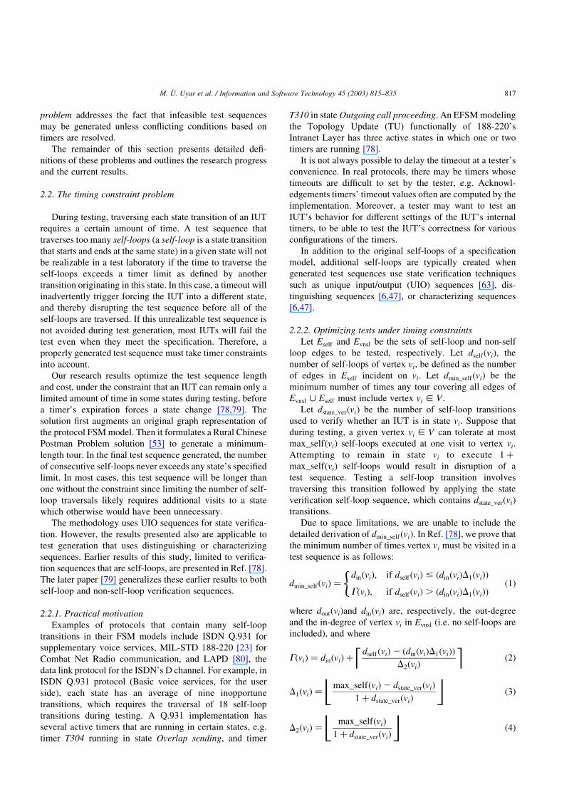
Fig. 2. Minimum-cost test sequence without self-loop repetition constraint.
M. U. Uyar et al. / Information and Software Technology 45 (2003) 815–835818
containing 40 edges (all ‘fake’ edges from vpð1Þi to vpð2Þi are
dropped).
Although longer than that of Fig. 2, the test sequence in
Fig. 3 is minimum-length with the introduced self-loop
constraint. During each visit to vertices v0; v1; v2 and v3; the
number of consecutive self-loop edges traversed is less than
or equal to the maximum allowed number of self-loop
traversals. Therefore, this test sequence is realizable in the
test laboratory.
2.3. The controllability problem
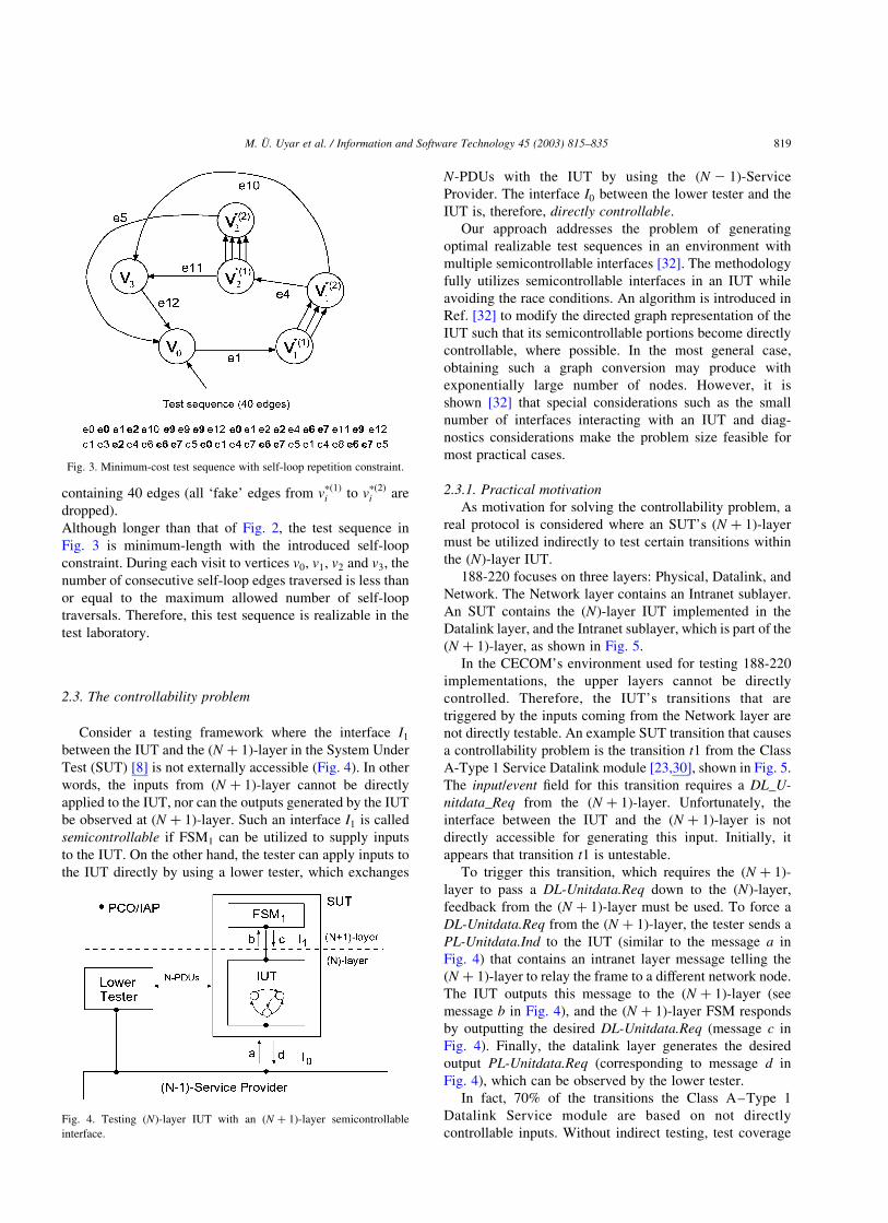
Consider a testing framework where the interface I1
between the IUT and the ðN þ 1Þ-layer in the System Under
Test (SUT) [8] is not externally accessible (Fig. 4). In other
words, the inputs from ðN þ 1Þ-layer cannot be directly
applied to the IUT, nor can the outputs generated by the IUT
be observed at ðN þ 1Þ-layer. Such an interface I1 is called
semicontrollable if FSM1 can be utilized to supply inputs
to the IUT. On the other hand, the tester can apply inputs to
the IUT directly by using a lower tester, which exchanges
N-PDUs with the IUT by using the ðN 2 1Þ-Service
Provider. The interface I0 between the lower tester and the
IUT is, therefore, directly controllable.
Our approach addresses the problem of generating
optimal realizable test sequences in an environment with
multiple semicontrollable interfaces [32]. The methodology
fully utilizes semicontrollable interfaces in an IUT while
avoiding the race conditions. An algorithm is introduced in
Ref. [32] to modify the directed graph representation of the
IUT such that its semicontrollable portions become directly
controllable, where possible. In the most general case,
obtaining such a graph conversion may produce with
exponentially large number of nodes. However, it is
shown [32] that special considerations such as the small
number of interfaces interacting with an IUT and diag-
nostics considerations make the problem size feasible for
most practical cases.
2.3.1. Practical motivation
As motivation for solving the controllability problem, a
real protocol is considered where an SUT’s ðN þ 1Þ-layer
must be utilized indirectly to test certain transitions within
the ðNÞ-layer IUT.
188-220 focuses on three layers: Physical, Datalink, and
Network. The Network layer contains an Intranet sublayer.
An SUT contains the ðNÞ-layer IUT implemented in the
Datalink layer, and the Intranet sublayer, which is part of the
ðN þ 1Þ-layer, as shown in Fig. 5.
In the CECOM’s environment used for testing 188-220
implementations, the upper layers cannot be directly
controlled. Therefore, the IUT’s transitions that are
triggered by the inputs coming from the Network layer are
not directly testable. An example SUT transition that causes
a controllability problem is the transition t1 from the Class
A-Type 1 Service Datalink module [23,30], shown in Fig. 5.
The input/event field for this transition requires a DL_U-
nitdata_Req from the ðN þ 1Þ-layer. Unfortunately, the
interface between the IUT and the ðN þ 1Þ-layer is not
directly accessible for generating this input. Initially, it
appears that transition t1 is untestable.
To trigger this transition, which requires the ðN þ 1Þ-
layer to pass a DL-Unitdata.Req down to the ðNÞ-layer,
feedback from the ðN þ 1Þ-layer must be used. To force a
DL-Unitdata.Req from the ðN þ 1Þ-layer, the tester sends a
PL-Unitdata.Ind to the IUT (similar to the message a in
Fig. 4) that contains an intranet layer message telling the
ðN þ 1Þ-layer to relay the frame to a different network node.
The IUT outputs this message to the ðN þ 1Þ-layer (see
message b in Fig. 4), and the ðN þ 1Þ-layer FSM responds
by outputting the desired DL-Unitdata.Req (message c in
Fig. 4). Finally, the datalink layer generates the desired
output PL-Unitdata.Req (corresponding to message d in
Fig. 4), which can be observed by the lower tester.
In fact, 70% of the transitions the Class A–Type 1
Datalink Service module are based on not directly
controllable inputs. Without indirect testing, test coverageFig. 4. Testing ðNÞ-layer IUT with an ðN þ 1Þ-layer semicontrollable
interface.
Fig. 3. Minimum-cost test sequence with self-loop repetition constraint.
M. U. Uyar et al. / Information and Software Technology 45 (2003) 815–835 819

would be seriously limited: only approximately 200
transitions out of 750 would be testable. However, by
applying the technique outlined in this paper, over 700 of
defined transitions (.95%) can be tested. The application
of the presented technique to 188-220 is described in more
detail in Ref. [31].
Similar controllability problems can also be pointed
out in testing the IEEE 802.2 LLC Connection
Component [32,41].
2.3.2. Optimizing tests with multiple semicontrollable
interfaces
To optimize tests with multiple semicontrollable inter-
faces, modeling SUT as a single FSM was proposed [32,33]. A
semicontrollable interface Ii is implemented as a separate
FIFO buffer. During testing, a buffer may be empty or store an
arbitrary sequence of inputs to the IUT generated indirectly
through Ii: For each Ii;we define variablevi that has a distinct
value for each permutation of inputs that the ith buffer can
hold. The proposed model consists of graph G (which
represents the IUT’s FSM) and the variables v1; v2;…;vF :
An FSM modeling the SUT can be obtained bye
expanding G and v1; v2;…;vF into G0ðV 0;E0Þ: An
algorithm for converting GðV ;EÞ to G0ðV 0;E0Þ pro-
ceeds as follows (a detailed description of the
algorithm along with its pseudocode is available in
Refs. [32,33]).
Step 0. Definitions:
Let Bi denote a sequence of inputs buffered at
the ith semicontrollable interface. Each state v0 [V 0 has two components: the original state v [ V ;
and the current configuration of F buffers, i.e.
v0 ¼ ðv; B1;…; BFÞ: The algorithm constructs all
possible buffer configurations with up to bi
inputs buffered at Ii:
Step 1. Initialize:
r0; root of G0; as ðr;B;…;BÞ (root of G and
configuration of empty buffers); E0 as empty set;
V 0 as {r0}; Q; queue of vertices, as V 0
Step 2. Repeat until Q is empty:
0.1. extract v0 ¼ ðvstart; B1;…; BFÞ as first element
from Q, where ðB1;…; BFÞ is current
configuration
0.2. given the current vertex v0 ¼ ðvstart; B1;…; BFÞ;
perform the following steps for each original
outgoing edge e ¼ ðvstart; vendÞ [ E :
– create new configuration ðB1;…;BFÞ based on
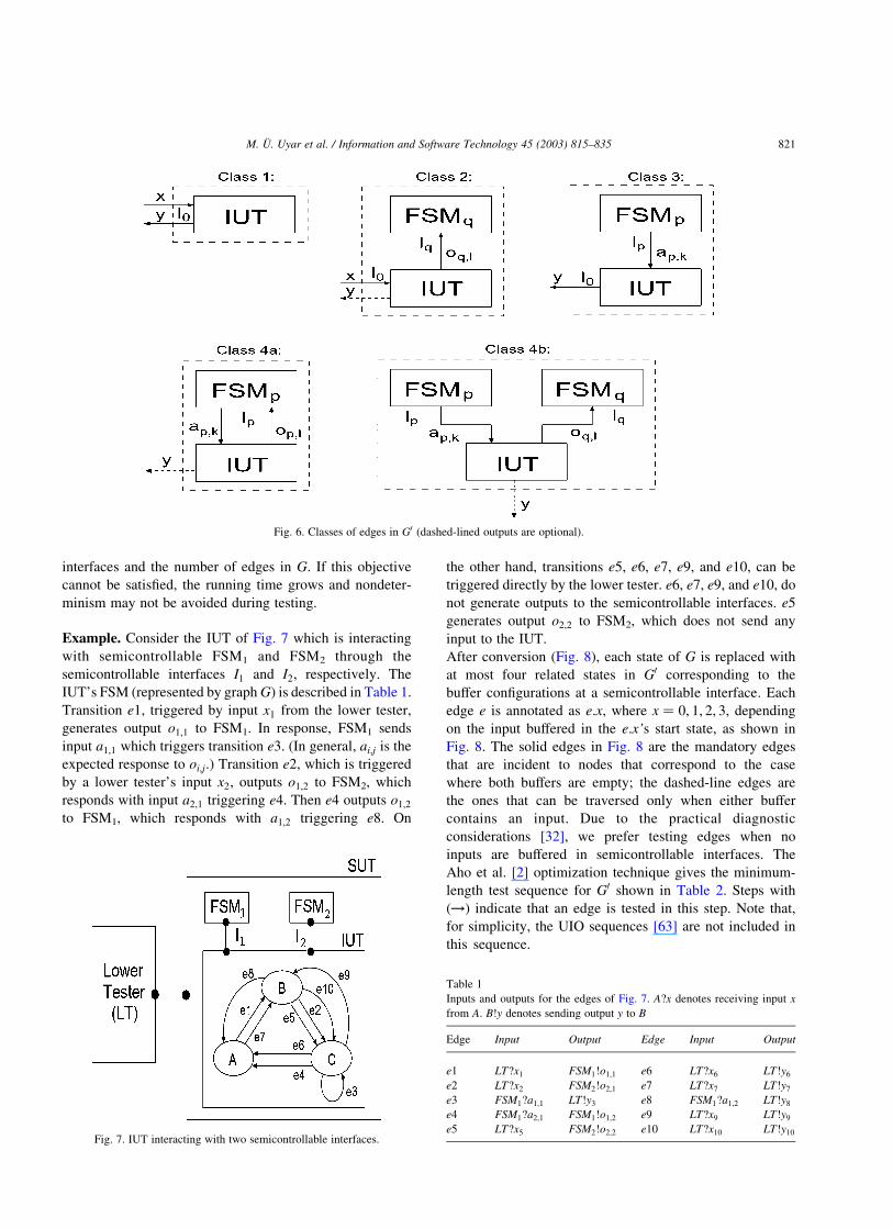
the class of e (Fig. 6):
– Class 1. e is triggered by an input from
and generates output(s) to an LT;
– Class 2. e is triggered by an input from an
LT and generates an output oq;l (buffered in
Bq to create a new configuration) at Iq;
– Class 3. e is triggered by ap;k (extracted
from Bp to create a new configuration)
from Ip and generates output(s) to an LT;
– Class 4. e is triggered by an input ap;k
from Ip and generates an output oq;l at Iq:
Apply rules for Class 3 and Class 2 to
create a new configuration.
– create new vertex v0new ¼ ðvend;B1;…;BFÞ [ V 0;
and new edge e0new ¼ ðv0; v0newÞ [ E0
– to avoid nondeterminism, include new edges
in E0 iff inputs in ðB1;…; BFÞ cannot trigger
other edges outgoing from vstart (as a result,
some edge combinations may not be possible
to traverse)
– append to Q end vertices v0new [ V 0 of new
edges included in E0
Step 3. Retain only strongly connected states:
remove from V 0 all vertices from which r0
cannot be reached, and remove from E0 all
edges incident to such vertices
Based on the practical considerations discussed in
Ref. [32], the algorithm can be refined to meet the following
objective: ‘generate a test sequence that, at any point in
time, avoids storing more than one input in only one of the
buffers (where possible).’ Satisfying this objective yields a
linear running time in the number of semicontrollable
Fig. 5. MIL-STD 188-220: example of the controllability problem.
M. U. Uyar et al. / Information and Software Technology 45 (2003) 815–835820
interfaces and the number of edges in G: If this objective
cannot be satisfied, the running time grows and nondeter-
minism may not be avoided during testing.
Example. Consider the IUT of Fig. 7 which is interacting
with semicontrollable FSM1 and FSM2 through the
semicontrollable interfaces I1 and I2; respectively. The
IUT’s FSM (represented by graph G) is described in Table 1.
Transition e1; triggered by input x1 from the lower tester,
generates output o1;1 to FSM1. In response, FSM1 sends
input a1;1 which triggers transition e3: (In general, ai;j is the
expected response to oi;j:) Transition e2; which is triggered
by a lower tester’s input x2; outputs o1;2 to FSM2, which
responds with input a2;1 triggering e4: Then e4 outputs o1;2
to FSM1, which responds with a1;2 triggering e8: On
the other hand, transitions e5; e6; e7; e9; and e10; can be
triggered directly by the lower tester. e6; e7; e9; and e10; do
not generate outputs to the semicontrollable interfaces. e5
generates output o2;2 to FSM2, which does not send any
input to the IUT.
After conversion (Fig. 8), each state of G is replaced with
at most four related states in G0 corresponding to the
buffer configurations at a semicontrollable interface. Each
edge e is annotated as e:x; where x ¼ 0; 1; 2; 3; depending
on the input buffered in the e:x’s start state, as shown in
Fig. 8. The solid edges in Fig. 8 are the mandatory edges
that are incident to nodes that correspond to the case
where both buffers are empty; the dashed-line edges are
the ones that can be traversed only when either buffer
contains an input. Due to the practical diagnostic
considerations [32], we prefer testing edges when no
inputs are buffered in semicontrollable interfaces. The
Aho et al. [2] optimization technique gives the minimum-
length test sequence for G0 shown in Table 2. Steps with
ð!Þ indicate that an edge is tested in this step. Note that,
for simplicity, the UIO sequences [63] are not included in
this sequence.
Fig. 6. Classes of edges in G0 (dashed-lined outputs are optional).
Fig. 7. IUT interacting with two semicontrollable interfaces.
Table 1
Inputs and outputs for the edges of Fig. 7. A?x denotes receiving input x
from A. B!y denotes sending output y to B
Edge Input Output Edge Input Output
e1 LT?x1 FSM1!o1;1 e6 LT?x6 LT!y6
e2 LT?x2 FSM2!o2;1 e7 LT?x7 LT!y7
e3 FSM1?a1;1 LT!y3 e8 FSM1?a1;2 LT!y8
e4 FSM1?a2;1 FSM1!o1;2 e9 LT?x9 LT!y9
e5 LT?x5 FSM2!o2;2 e10 LT?x10 LT!y10
M. U. Uyar et al. / Information and Software Technology 45 (2003) 815–835 821

2.4. Inconsistency detection and elimination problem
Feasible test sequence generation is essential for assuring
the proper operation and interoperability of different
components in computer and communication systems. The
use of formal description languages such as VHDL and
Estelle enable the precise description of such systems and
help minimize the implementation errors due to misinter-
pretations. However, the specifications written in VHDL
and Estelle are often extended FSMs (EFSMs), making the
automated test generation a more complex task due to
possible inconsistencies among the action and condition
variables [25,26].
We studied the problem of generating feasible test
sequences for the EFSM by analyzing the interdependencies
among the action and condition variables of the EFSM
models. In the earlier phases of this research, action and
condition inconsistencies in the EFSM models were defined
[81,82]. It has been shown that once the inconsistencies are
eliminated, the existing FSM-based test generation methods
can be used to generate feasible test sequences from the
resulting consistent EFSM graphs.
The algorithms for the detection and elimination of
inconsistencies in EFSM models utilize symbolic execution,
linear programming, and graph splitting methods. After all
inconsistencies are eliminated, all paths of the final resulting
EFSM graph are feasible and can be used as an input to the
FSM-based test generation methods. The basic concepts for
the inconsistency elimination algorithms were outlined in
Ref. [82], which were later generalized to include graphs
with loops [25,77]. The formal descriptions of the incon-
sistency detection and elimination algorithms have been
given in Refs. [25,26].
2.4.1. Action inconsistencies
If there is no solution for the set of equations formed
by the actions of an edge ei and the condition of another
edge ej; where headðejÞ can be reached from tailðeiÞ or
Fig. 8. Graph transformation applied to the graph of Fig. 7. Mandatory and optional edges appear in solid and dashed lines, respectively.
Table 2
Minimum-length test sequence for the IUT of Fig. 7
Step Edge Input Output Step Edge Input Output
!1 e1:0 LT?x1 FSM1!o1;1 8 e7:2 LT?x7 LT!y7
2 e5:1 LT?x5 FSM2!o2;2 !9 e8:2 FSM1?a1;2 LT!y8
!3 e3:1 FSM1?a1;1 LT!y3 10 e7:0 LT?x7 LT!y7
!4 e6:0 LT?x6 LT!y6 !11 e5:0 LT?x5 FSM2!o2;2
!5 e7:0 LT?x7 LT!y7 !12 e9:0 LT?x9 LT?y9
!6 e2:0 LT?x2 FSM2!o2;1 13 e10:0 LT?x10 LT!y10
!7 e4:3 FSM2?a2;1 FSM1!o1;2 14 e6:0 LT?x6 LT!y6
M. U. Uyar et al. / Information and Software Technology 45 (2003) 815–835822

headðejÞ ¼ tailðeiÞ; then the two edges of ei and ej are said to
have an action inconsistency (for an edge directed from
node va to node vb; the head and tail nodes are defined as va
and vb; respectively).
For example, in Fig. 9, there is an action inconsistency
between the action of e1 and the condition of e8 due to
variable b:
In general, the effects of the edge actions on variables
(i.e. variable modifications) can be represented as matrices.
For an EFSM graph with m variables, var1; var2;…; varm; a
pair of matrices Aðm £ mÞ and Bðm £ 1Þ called the
modification matrix and the modification vector, respect-
ively, are defined.
The accumulated effects of the actions in the paths
leading to a node vi can be represented by a set of Action
Update Matrix pairs defined as
AUMðvi; JÞ ¼ {Avi;0; ~Bvi ;0
;Avi;1; ~Bvi ;1
;…;Avi;J21; ~Bvi;J21} ð8Þ
where Avi;k; ~Bvi ;k
; and J are the kth modification matrix, kth
modification vector ð0 # k , JÞ; and the number of AUM
pairs associated with vi; respectively. The symbolic values
of a variable varr are represented in the rth rows in
AUMðvi; JÞ: Only one AUM pair, where A and ~B are
initialized to the identity matrix and to a zero vector,
respectively, is created for the initial node.
The algorithm for detecting and resolving action
inconsistencies can be summarized as follows:
† Determine the symbolic values of the variables at each
node reached in the MBF (modified breadth-first [25,26])
graph traversal.
† Pass the effect of actions onto the condition variables.
† For each node vi; based on the symbolic values of the
variables of running timers, determine the feasibility of
each outgoing edge whose conditions use differently
modified variables at vi:
† For each action inconsistency, split the graph such
that the two edges (with inconsistent actions and
conditions) are placed in two different sub-graphs.
The number of AUM pairs associated with vi solely
depends on the number of different ways in which the
actions of the edges leading to vi modify variables. If the
overall variable modifications of the actions of any two
paths leading to vi are the same, only one AUM pair is
sufficient to account for the effects of the actions in the two
paths. Therefore, only unique AUM pairs are associated
with vi (Section 2.4.3).
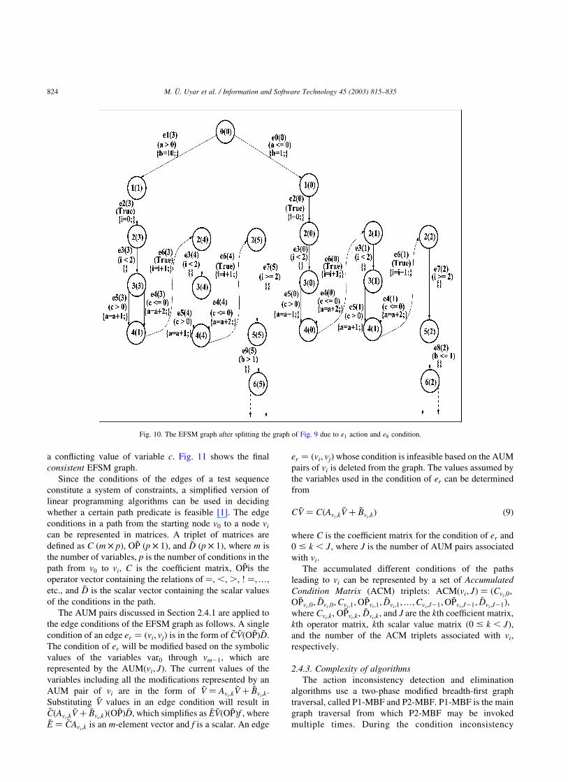
Symbolic execution is utilized in the construction of
AUM pairs. When an action inconsistency is detected, the
EFSM graph is split from the node where the conflict
occurs. The analysis continues until all action incon-
sistencies are eliminated. By applying the algorithms in
Refs. [25,26,77], the resulting EFSM graph after the
action conflicts are eliminated is shown in Fig. 10.
2.4.2. Condition inconsistencies
After all action conflicts are eliminated from the EFSM
graph, the next step involves the detection and elimination
of condition inconsistencies. The edges ei and ej are said to
have a condition inconsistency if there is no solution for the
set of equations formed by the accumulated conditions of
the edges of a sub-path e1e2· · ·ei and an edge ej; where
headðejÞ can be reached from tailðeiÞ or headðejÞ ¼ tailðeiÞ.
The process of condition inconsistency detection and
resolution can be outlined as:
† Collect the accumulated conditions of the edges leading
to vi reached with the DF graph traversal.
† Based on the symbolic values of the variables, determine
if there is an edge reachable from vi whose condition(s)
conflict with the ACM triplets of vi:
† Upon finding two edges whose conditions conflict,
split the graph and place the two edges in separate
sub-graphs.
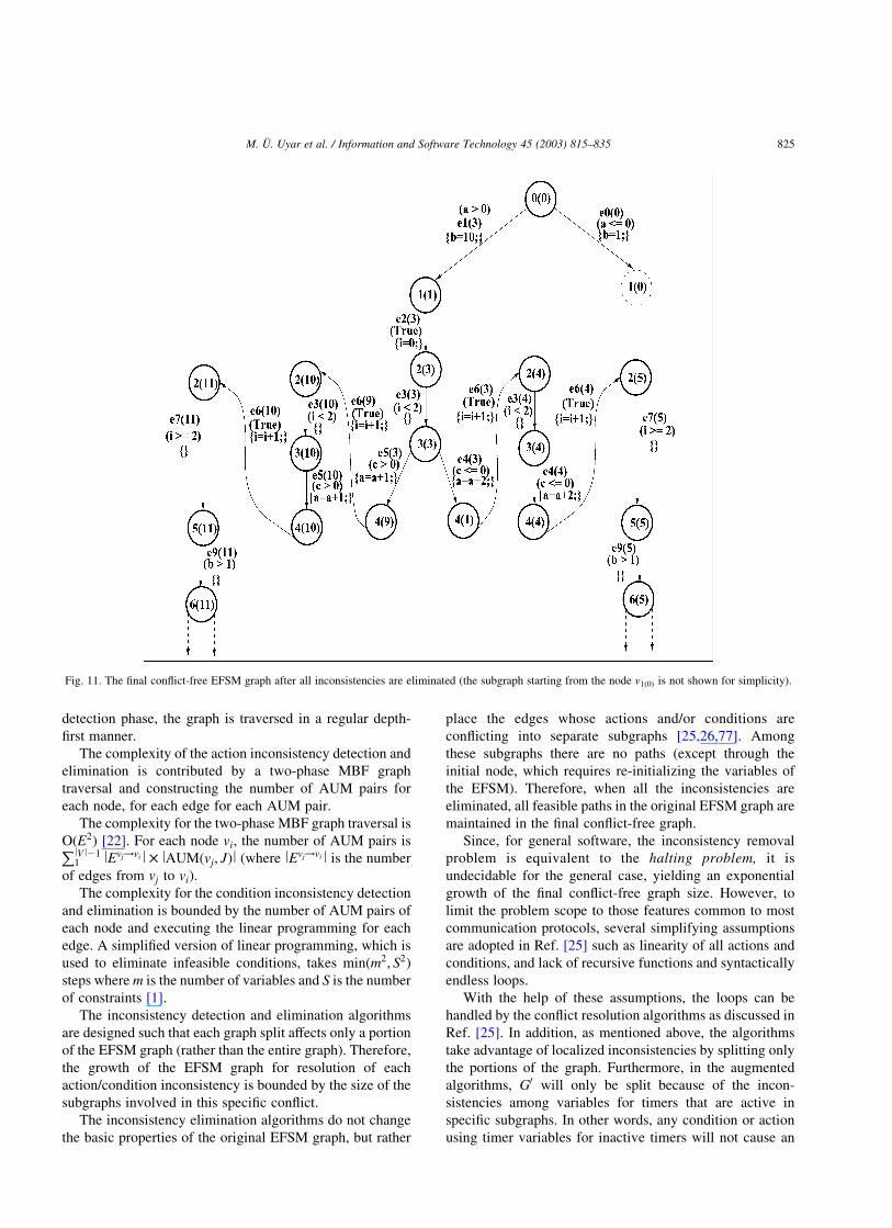
In Fig. 10, for example, there is a condition inconsistency
between the edges of e5ð0Þ and e4ð1Þ since each edge requires
Fig. 9. An EFSM graph with inconsistencies.
M. U. Uyar et al. / Information and Software Technology 45 (2003) 815–835 823
a conflicting value of variable c: Fig. 11 shows the final
consistent EFSM graph.
Since the conditions of the edges of a test sequence
constitute a system of constraints, a simplified version of
linear programming algorithms can be used in deciding
whether a certain path predicate is feasible [1]. The edge
conditions in a path from the starting node v0 to a node vi
can be represented in matrices. A triplet of matrices are
defined as C ðm £ pÞ; O ~P ðp £ 1Þ; and ~D ðp £ 1Þ; where m is
the number of variables, p is the number of conditions in the
path from v0 to vi; C is the coefficient matrix, O ~Pis the
operator vector containing the relations of ¼;,;.; ! ¼;…;
etc., and ~D is the scalar vector containing the scalar values
of the conditions in the path.
The AUM pairs discussed in Section 2.4.1 are applied to
the edge conditions of the EFSM graph as follows. A single
condition of an edge er ¼ ðvi; vjÞ is in the form of ~C ~VðO ~PÞ ~D:
The condition of er will be modified based on the symbolic
values of the variables var0 through vm21; which are
represented by the AUMðvi; JÞ: The current values of the
variables including all the modifications represented by an
AUM pair of vi are in the form of ~V ¼ Avi;k~V þ ~Bvi;k
:
Substituting ~V values in an edge condition will result in~CðAvi;k
~V þ ~Bvi;kÞðO ~PÞ ~D; which simplifies as ~E ~VðO ~PÞf ; where
~E ¼ ~CAvi ;kis an m-element vector and f is a scalar. An edge
er ¼ ðvi; vjÞ whose condition is infeasible based on the AUM
pairs of vi is deleted from the graph. The values assumed by
the variables used in the condition of er can be determined
from
C ~V ¼ CðAvi ;k~V þ ~Bvi ;k
Þ ð9Þ
where C is the coefficient matrix for the condition of er and
0 # k , J; where J is the number of AUM pairs associated
with vi:
The accumulated different conditions of the paths
leading to vi can be represented by a set of Accumulated
Condition Matrix (ACM) triplets: ACMðvi; JÞ ¼ ðCvi;0;
O ~Pvi ;0; ~Dvi ;0
;Cvi;1;O ~Pvi;1
; ~Dvi;1;…;Cvi;J21;O ~Pvi;J21; ~Dvi;J21Þ;
where Cvi;k; O ~Pvi;k
; ~Dvi ;k; and J are the kth coefficient matrix,
kth operator matrix, kth scalar value matrix ð0 # k , JÞ;
and the number of the ACM triplets associated with vi;
respectively.
2.4.3. Complexity of algorithms
The action inconsistency detection and elimination
algorithms use a two-phase modified breadth-first graph
traversal, called P1-MBF and P2-MBF. P1-MBF is the main
graph traversal from which P2-MBF may be invoked
multiple times. During the condition inconsistency
Fig. 10. The EFSM graph after splitting the graph of Fig. 9 due to e1 action and e8 condition.
M. U. Uyar et al. / Information and Software Technology 45 (2003) 815–835824
detection phase, the graph is traversed in a regular depth-
first manner.
The complexity of the action inconsistency detection and
elimination is contributed by a two-phase MBF graph
traversal and constructing the number of AUM pairs for
each node, for each edge for each AUM pair.
The complexity for the two-phase MBF graph traversal is
OðE2Þ [22]. For each node vi; the number of AUM pairs isPlV l211 lEvj!vi l £ lAUMðvj; JÞl (where lEvj!vi l is the number
of edges from vj to vi).
The complexity for the condition inconsistency detection
and elimination is bounded by the number of AUM pairs of
each node and executing the linear programming for each
edge. A simplified version of linear programming, which is
used to eliminate infeasible conditions, takes minðm2; S2Þ
steps where m is the number of variables and S is the number
of constraints [1].
The inconsistency detection and elimination algorithms
are designed such that each graph split affects only a portion
of the EFSM graph (rather than the entire graph). Therefore,
the growth of the EFSM graph for resolution of each
action/condition inconsistency is bounded by the size of the
subgraphs involved in this specific conflict.
The inconsistency elimination algorithms do not change
the basic properties of the original EFSM graph, but rather
place the edges whose actions and/or conditions are
conflicting into separate subgraphs [25,26,77]. Among
these subgraphs there are no paths (except through the
initial node, which requires re-initializing the variables of
the EFSM). Therefore, when all the inconsistencies are
eliminated, all feasible paths in the original EFSM graph are
maintained in the final conflict-free graph.
Since, for general software, the inconsistency removal
problem is equivalent to the halting problem, it is
undecidable for the general case, yielding an exponential
growth of the final conflict-free graph size. However, to
limit the problem scope to those features common to most
communication protocols, several simplifying assumptions
are adopted in Ref. [25] such as linearity of all actions and
conditions, and lack of recursive functions and syntactically
endless loops.
With the help of these assumptions, the loops can be
handled by the conflict resolution algorithms as discussed in
Ref. [25]. In addition, as mentioned above, the algorithms
take advantage of localized inconsistencies by splitting only
the portions of the graph. Furthermore, in the augmented
algorithms, G0 will only be split because of the incon-
sistencies among variables for timers that are active in
specific subgraphs. In other words, any condition or action
using timer variables for inactive timers will not cause an
Fig. 11. The final conflict-free EFSM graph after all inconsistencies are eliminated (the subgraph starting from the node v1ð0Þ is not shown for simplicity).
M. U. Uyar et al. / Information and Software Technology 45 (2003) 815–835 825
inconsistency, and thus will not contribute to the growth of
the graph. This methodology has been applied to two real-
life protocols, resulting in conflict-free graphs that did not
grow exponentially (Section 4).
2.4.4. The conflicting timers problem
To ensure feasibility of tests in a laboratory, automated
test generation for network protocols with timer require-
ments must consider conflicting conditions based on a
protocol’s timers. The conflicting timers problem is a
special case of the inconsistency detection and elimination
problem. There are two simplifying features of the
conflicting timers problem: (1) timer-related variables are
linear, and (2) the values of time-keeping variables
implicitly increase with time. The original inconsistency
elimination algorithms [25,26,77,82] are thus augmented to
make them more efficient for the EFSM models with timer
variables.
Suppose that a protocol specification defines a set of
timers K ¼ {tm1;…; tmlKl}; such that a timer tmj may be
started and stopped by arbitrary transitions defined in the
specification. Each timer tmj can be associated with a
boolean variable Tj whose value is true if tmj is running, and
false if tmj is not running. It is also described by time-
keeping variable fj that measures the time since a timer is
activated. Let f be a time formula obtained from variables
T1;…;Tk by using logical operands ^; _; and : : Suppose
that a specification contains transitions with time conditions
of a form ‘if f’ for some time formula f: It is clear that there
may exist infeasible paths in an FSM modeling a protocol, if
two or more edges in a path have inconsistent conditions.
For example, for transitions e1 : if ðTjÞ then {w1} and e2 :
if ð: TjÞ then {w2}; a path ðe1; e2Þ is inconsistent unless
the action of w1 in e1 sets Tj to false (which happens when
timer tmj expires in transition e1).
Our research developed a new model for testing real-time
protocols with multiple timers [34], which captures complex
timing dependencies by using simple linear expressions
involving timer-related variables. The model, specifically
designed for testing purposes, avoids performing a full
reachability analysis and significantly limits the explosive
growth of the number of test scenarios. These goals are
achieved by incorporating certain rules for the graph
traversal without reducing the set of testable transitions.
The technique also models a realistic testing framework in
which each I/O exchange takes a certain time to realize, and
a tester has an ability to turn timers on and off in arbitrary
transitions and to algorithmically find proper timeout
settings.
The augmented inconsistency removal algorithms differ
from the original ones (Sections 2.4.1 and 2.4.2) as follows.
In a generic EFSM model, all variables are treated equally.
However, in the model presented in this paper, a
relationship between boolean Tj and time-keeping variable
fj (for timer tmj) is exploited to prevent unnecessary growth
of the state space of G00: In the original algorithms, when
variable x is used in actions of edges incoming to vp; but is
not used in conditions of edges reachable from vp; vertex vp
and the following graph are not split.
This rule cannot be used in the model presented here in
its original form because, for each timer tmj; fj is used in
actions and conditions of all edges. Therefore, splits would
occur every time. However, fj‘s value is significant only if Tj
is 1 (we will say that fj is either active or inactive). The edge
conditions (derived from those in Section 2.4.2) in the
model are defined so that each component involving
inactive fj would evaluate to true all the time. Thus, inactive
fj cannot create any inconsistencies, and its component can
be pruned from a condition. The rule for identifying an
inconsistency should be modified as follows: when variable
x is used in actions of edges incoming to vp; and either (1) x
is not used in conditions of edges reachable from vp or (2) x
is used in these conditions, but it is inactive in AUMðvpÞ;
vertex vp and the following graph are not split.
In the test cases delivered to CECOM (Section 4),
conflicting conditions based on 188-220’s timers are
resolved by manually expanding EFSMs based on the set
of conflicting timers. This procedure results in test
sequences that are far from minimum-length. The technique
presented here allows us to automatically generate conflict-
free test sequences for 188-220. The software implemen-
tation of these algorithms developed at UD and CCNY is
described in Section 3.
2.5. Related work
Test generation from EFSM models has been an active
research area. Sarikaya et al. used the functional program
testing approach to generate test sequences from the EFSMs
[64]. Software data flow testing approaches have been used
to generate tests for the communication protocols [71–73].
Ural applied the all-uses [73,61] criterion, used for testing
software written in block structured programming
languages, to Estelle [13,14] specification of protocols.
Miller and Paul [55] introduced a method to generate tests
for both control and data for EFSM models. Chanson and
Zhu [17] proposed a test generation method which considers
both the control flow and data aspects of the EFSM models.
Lee and Yannakakis [50] provided a method to convert a
class of EFSMs, where input variables are assumed to have
finite domains, into equivalent FSMs. For a restricted class
of LOTOS expressions, called P-LOTOS, Higashino and
Bochmann propose a method that provides solutions to a set
of interrelated problems such as the test case derivation and
the detections of nonexecutable branches, deadlocks, and
nondeterminism [36].
Although these methods made significant contributions
towards the test generation from the EFSMs, the inclusion
of infeasible paths in the test sequences may be inevitable
since the underlying models are EFSMs. Therefore, without
a proper analysis of the interdependencies among the
variables used in the actions and conditions of the EFSMs,
M. U. Uyar et al. / Information and Software Technology 45 (2003) 815–835826
considerable effort may be wasted on test generation since
the infeasible portions of these test sequences will be
discarded later.
Among the reported techniques for testing protocols with
timers, some produce a prohibitively large number of test
cases [16,65], which reduces their practical applicability.
Other approaches [24,28] sample the time space with
random granularity, which, unfortunately, is not necessarily
associated with the real transitions’ duration defined by the
specification. In other methods, when the order of possible
timer expirations is not known, undesirable nondeterminism
and infeasible test cases may be introduced [45]. Some test
generation algorithms may take an unacceptably long time
to terminate for real-life protocols because many test
sequences may be generated before the one verified as
executable is found [37].
3. Software for automated test generation
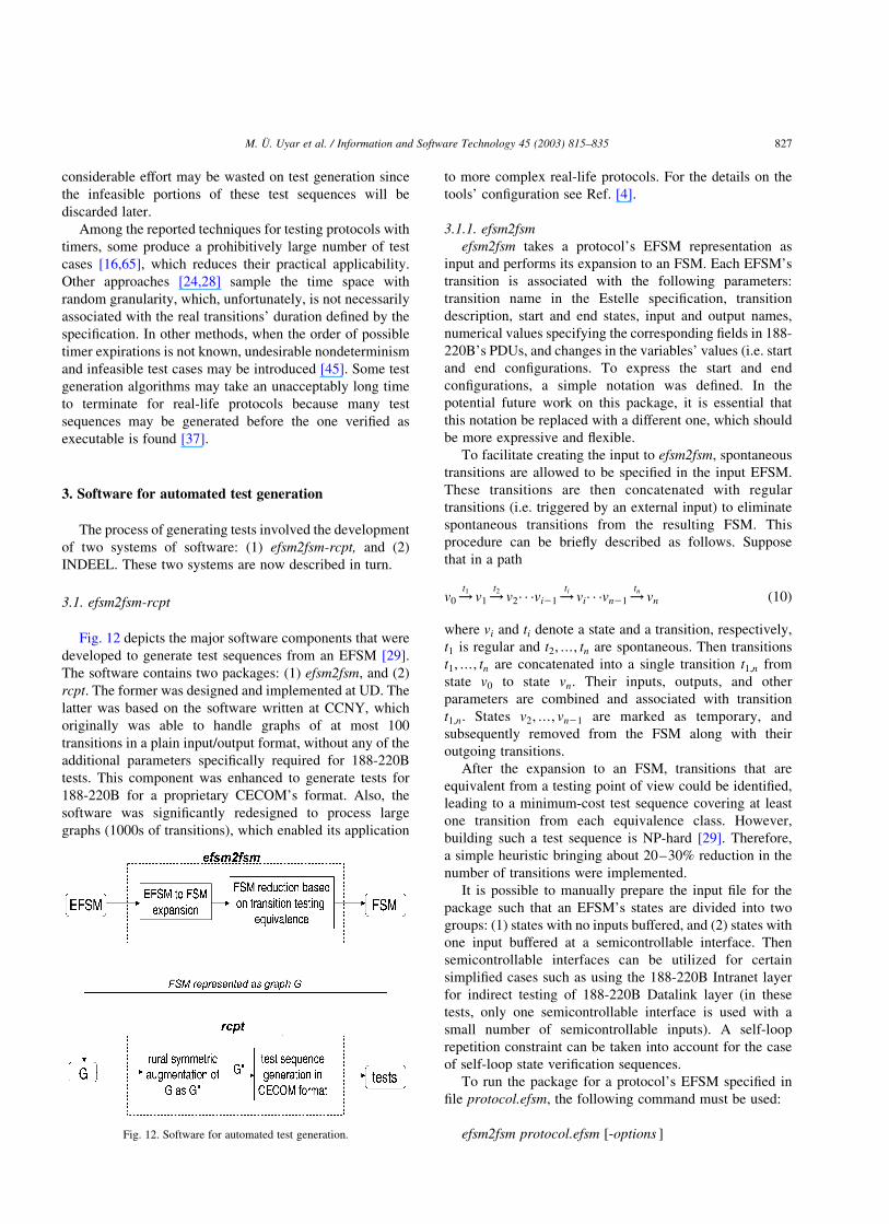
The process of generating tests involved the development
of two systems of software: (1) efsm2fsm-rcpt, and (2)
INDEEL. These two systems are now described in turn.
3.1. efsm2fsm-rcpt
Fig. 12 depicts the major software components that were
developed to generate test sequences from an EFSM [29].
The software contains two packages: (1) efsm2fsm, and (2)
rcpt. The former was designed and implemented at UD. The
latter was based on the software written at CCNY, which
originally was able to handle graphs of at most 100
transitions in a plain input/output format, without any of the
additional parameters specifically required for 188-220B
tests. This component was enhanced to generate tests for
188-220B for a proprietary CECOM’s format. Also, the
software was significantly redesigned to process large
graphs (1000s of transitions), which enabled its application
to more complex real-life protocols. For the details on the
tools’ configuration see Ref. [4].
3.1.1. efsm2fsm
efsm2fsm takes a protocol’s EFSM representation as
input and performs its expansion to an FSM. Each EFSM’s
transition is associated with the following parameters:
transition name in the Estelle specification, transition
description, start and end states, input and output names,
numerical values specifying the corresponding fields in 188-
220B’s PDUs, and changes in the variables’ values (i.e. start
and end configurations. To express the start and end
configurations, a simple notation was defined. In the
potential future work on this package, it is essential that
this notation be replaced with a different one, which should
be more expressive and flexible.
To facilitate creating the input to efsm2fsm, spontaneous
transitions are allowed to be specified in the input EFSM.
These transitions are then concatenated with regular
transitions (i.e. triggered by an external input) to eliminate
spontaneous transitions from the resulting FSM. This
procedure can be briefly described as follows. Suppose
that in a path
v0 !t1
v1 !t2
v2· · ·vi21 !ti
vi· · ·vn21 !tn
vn ð10Þ
where vi and ti denote a state and a transition, respectively,
t1 is regular and t2;…; tn are spontaneous. Then transitions
t1;…; tn are concatenated into a single transition t1;n from
state v0 to state vn: Their inputs, outputs, and other
parameters are combined and associated with transition
t1;n: States v2;…; vn21 are marked as temporary, and
subsequently removed from the FSM along with their
outgoing transitions.
After the expansion to an FSM, transitions that are
equivalent from a testing point of view could be identified,
leading to a minimum-cost test sequence covering at least
one transition from each equivalence class. However,
building such a test sequence is NP-hard [29]. Therefore,
a simple heuristic bringing about 20–30% reduction in the
number of transitions were implemented.
It is possible to manually prepare the input file for the
package such that an EFSM’s states are divided into two
groups: (1) states with no inputs buffered, and (2) states with
one input buffered at a semicontrollable interface. Then
semicontrollable interfaces can be utilized for certain
simplified cases such as using the 188-220B Intranet layer
for indirect testing of 188-220B Datalink layer (in these
tests, only one semicontrollable interface is used with a
small number of semicontrollable inputs). A self-loop
repetition constraint can be taken into account for the case
of self-loop state verification sequences.
To run the package for a protocol’s EFSM specified in
file protocol.efsm, the following command must be used:
efsm2fsm protocol.efsm [-options ]Fig. 12. Software for automated test generation.
M. U. Uyar et al. / Information and Software Technology 45 (2003) 815–835 827
producing two files protocol.fsm and protocol.stat. The
former contains the output FSM. All information associated
with transitions in the input EFSM is preserved. This
enables the rcpt package to populate the fields defined in the
CECOM format for test sequences. The latter file contains
statistics such as the number of states and transitions in the
EFSM/FSM, and the percentage effectiveness of the
reduction heuristic.
Note that the original EFSM to FSM conversion
technique implemented should be replaced by the appli-
cation of the inconsistency elimination algorithms
implemented in INDEEL (Section 3.2). Using INDEEL to
eliminate inconsistencies results in a conflict-free EFSM
that is significantly smaller than the FSM.
3.1.2. rcpt
The FSM produced by efsm2fsm is then fed to rcpt,
which builds a corresponding directed graph representation
G. Then, network flow techniques are applied to find a rural
symmetric augmentation of G as G00: Finally, rcpt finds an
Euler tour of G00; and outputs to a file a resulting test
sequence conforming to the CECOM format. It is proven
[29] that if G has either a reset capability or self-loop
property (as defined by Aho et al. [2]), an Euler tour always
exists for G00:
Suppose that protocol.fsm is an input file containing a
protocol’s FSM. Then the following command runs the package:
rcpt [-cecom/-plain ] protocol.fsm output_file
where plain option refers to a plain input/output file format.
protocol.fsm file in plain format can be prepared manually.
The cecom option selects test generation in the CECOM
format. In this case, the input file protocol.fsm should be
generated by the efsm2fsm package. The tests are stored in the
number offiles named protocol.i, where i is the index of a test
group.
3.2. INDEEL: software for inconsistency detection
and elimination
A software package, called INDEEL (INconsistencies
DEtection and ELimination), has been implemented at
CCNY based on the inconsistency elimination algorithms
given in Refs. [25,26,77]. As part of the ongoing
collaboration between the CCNY and the UD, the
application of these algorithms has been extended to
generate test sequences for the protocols with conflicting
timers such as 188-220.
INDEEL contains 15,000 þ lines of algorithmic C code.
As its input, the software reads a user specified file
containing the description of an EFSM graph with the
following properties:
† The specification consists of a single process and thus
there are no communicating EFSMs.
† If the specification contains function calls, they can be
described within the process with a simple
transformation.
† Pointers, recursive functions, and syntactically endless
loops are assumed not to be present in the specification.
† All conditions and actions are linear.
Overall complexity of the algorithms used in INDEEL was
discussed in Section 2.4.3. INDEEL uses an iterative
approach: every time an action or condition inconsistency is
detected and eliminated, an intermediate output graph is
generated in a file, using the same format as in the input file.
This intermediate output file then becomes the new input file
to INDEEL for continued analysis. This iterative procedure is
repeated until the graph becomes free of inconsistencies. The
intermediate and the final output graphs are provided as files.
INDEEL starts its analysis by considering the action
inconsistencies; it then proceeds to the detection and
elimination of the condition inconsistencies (if any). During
the analysis of the action inconsistencies, INDEEL
constructs a set of Action Update Matrix (AUM) pairs for
each node. The AUM pairs represent the effects of the
actions of the traversed edges leading to a given node vi:
Similarly, the accumulated different conditions of the paths
leading to vi can be represented as a set of Accumulated
Condition Matrix (ACM) triplets containing the coeffi-
cients, operators, and constants of the edge conditions.
To reduce the space complexity, during the AUM and
ACM constructions, the software uses a single matrix called
path_matrices in which the numbers of the edges in the
paths from the initial node to vi are stored.
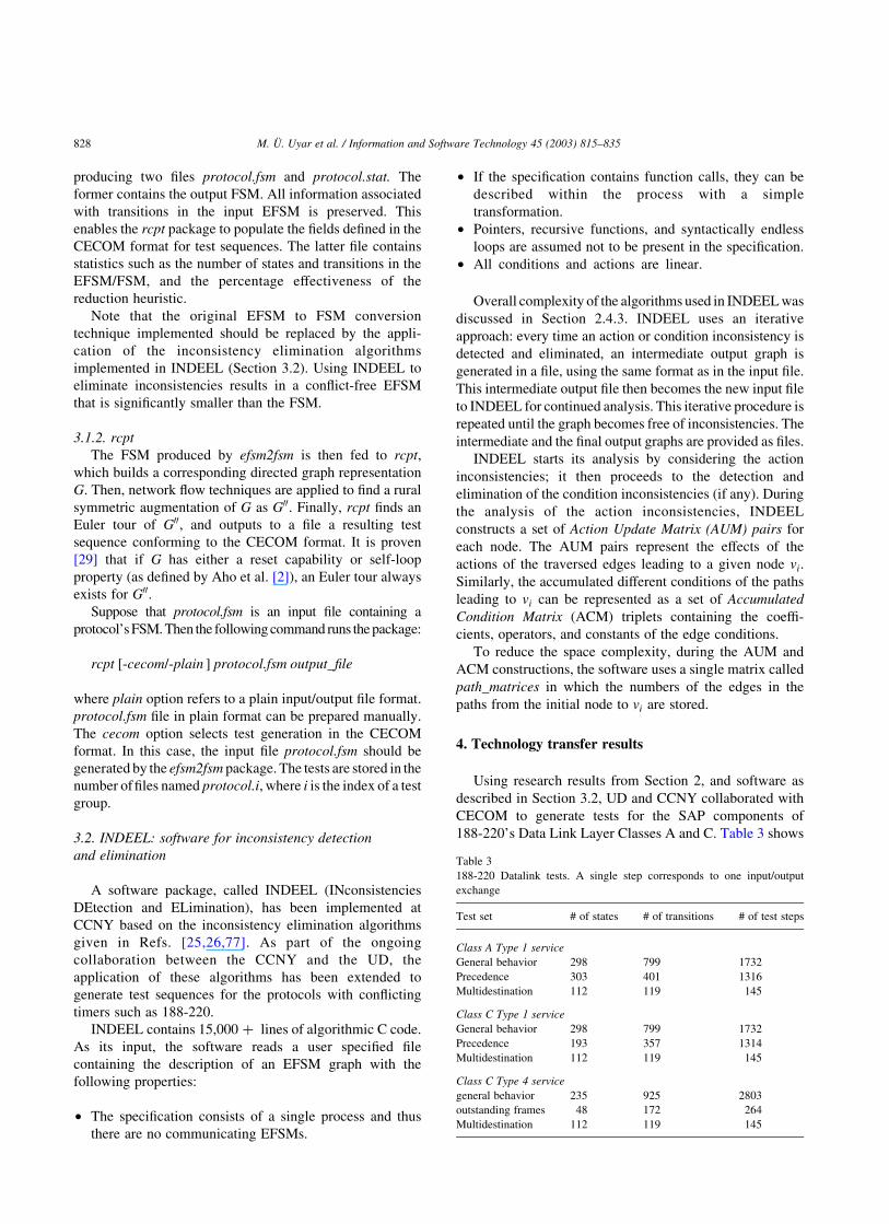
4. Technology transfer results
Using research results from Section 2, and software as
described in Section 3.2, UD and CCNY collaborated with
CECOM to generate tests for the SAP components of
188-220’s Data Link Layer Classes A and C. Table 3 shows
Table 3
188-220 Datalink tests. A single step corresponds to one input/output
exchange
Test set # of states # of transitions # of test steps
Class A Type 1 service
General behavior 298 799 1732
Precedence 303 401 1316
Multidestination 112 119 145
Class C Type 1 service
General behavior 298 799 1732
Precedence 193 357 1314
Multidestination 112 119 145
Class C Type 4 service
general behavior 235 925 2803
outstanding frames 48 172 264
Multidestination 112 119 145
M. U. Uyar et al. / Information and Software Technology 45 (2003) 815–835828
the sizes of the expanded EFSMs and the tests that were
generated from them. For example, the precedence tests set
for Class A-Type 1 Service was based on an expanded
EFSM of 303 states and 401 transitions. The minimum-
length test sequence generated for this machine consists of
1316 input/output pairs covering every transition in the
expanded EFSM at least once.
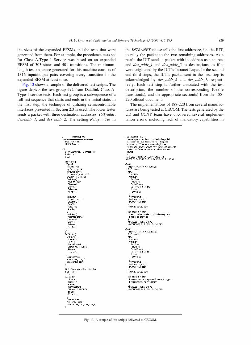
Fig. 13 shows a sample of the delivered test scripts. The
figure depicts the test group #92 from Datalink Class A-
Type 1 service tests. Each test group is a subsequence of a
full test sequence that starts and ends in the initial state. In
the first step, the technique of utilizing semicontrollable
interfaces presented in Section 2.3 is used. The lower tester
sends a packet with three destination addresses: IUT-addr,
des-addr_1, and des_addr_2. The setting Relay ¼ Yes in
the INTRANET clause tells the first addressee, i.e. the IUT,
to relay the packet to the two remaining addresses. As a
result, the IUT sends a packet with its address as a source,
and des_addr_1 and des_addr_2 as destinations, as if it
were originated by the IUT’s Intranet Layer. In the second
and third steps, the IUT’s packet sent in the first step is
acknowledged by des_addr_2 and des_addr_1, respect-
ively. Each test step is further annotated with the test
description, the number of the corresponding Estelle
transition(s), and the appropriate section(s) from the 188-
220 official document.
The implementations of 188-220 from several manufac-
tures are being tested at CECOM. The tests generated by the
UD and CCNY team have uncovered several implemen-
tation errors, including lack of mandatory capabilities in
Fig. 13. A sample of test scripts delivered to CECOM.
M. U. Uyar et al. / Information and Software Technology 45 (2003) 815–835 829

Datalink layer, and problems with multi-hop Intranet
Relaying.
5. Conclusions: improvements to protocol development
process
5.1. Integration of Estelle into system development
Traditional sequential process of system development is
known to be inefficient since it allows unnecessary
duplication and does not facilitate tracking of rapidly
changing technology. With 188-220 as a critical component,
a synergistic framework for C4I (Command, Control,
Communications, Computers, and Intelligence) systems
development has been established [27] (Fig. 14). It
combines several parallel activities: developing protocol
standards and specifications, formally specifying protocols
in Estelle, building conformance tester hardware and
software, ‘field testing’, modeling and simulation, as well
as resolving and documenting the solutions to standards-
related technical issues by the Joint CNR Working Group.
(WG participants include representatives from DoD ser-
vices/agencies, industry, and academia.)
Estelle[40]wasselectedas theFDTforspecifying188-220
protocolsuite foranumber reasons.Thelanguage issupported
by a set of tools combined in the Development Toolset (EDT)
[11] (accessible through http://www-lor.int-evry.fr/edt/),
which is composed of a simulator/debugger with a Message
Sequence Chart trace generator, a Universal Generator (test
drivers generator, decompiler, distributed specification gen-
erator-splitter), a state/event tables generator, a browser, a
pretty printer, and a graphical editor [66]. More than 30
universities, research centres and industrial laboratories
around the world are licensed to use the EDT tools, including:
University of Delaware (USA), Concordia University
(Canada), Centro Studi e Laboratori Telecomunicazioni
(Italy), Joint Interoperability Test Comand-Open Systems
Environment Test Laboratory (Ft. Huachuca, Arizona, USA).
Using formal methods as part of this process helped
create a high quality protocol standard, which is robust and
efficient. Due to the structured nature of Estelle, the
specification process progressed at an accelerated pace
compared to other standards. 188-220 was completed on
time, setting a rare example in the protocol standards arena.
The existence of a formal specification allowed the
researchers at UD and CCNY to extract modeling
information in order to solve a number of theoretical
problems. This resulted in the development of new testing
methodologies. By applying these new results, the con-
formance tests for 188-220 were generated while the
protocol was still evolving. Performing initial conformance
tests on prototypes uncovered several interoperability errors
early in the development process. Following this success of
the 188-220 development, the synergistic efforts to develop
C4I systems with the help of formal methods serves as a
model for DoD standards process and development for the
future [27].
5.2. Advantages of formal methods in eliminating protocol
errors
In addition to the vagueness introduced by a natural
language description, ambiguities and contradictions are
difficult to detect when related protocol functionalities are
defined in different document sections separated by several
pages of unrelated text. Such problems are eliminated in a
formal Estelle specification. All actions in a particular
context are defined in one place within the Estelle
specification. The specifications make the conditions for
state transitions explicit through Estelle constructs. Indeed,
the very process of creating these constructs enables formal
specifiers to detect some of these types of ambiguities which
are difficult to see in normal reading of a document written
in English.
5.3. Observations on applicability of formal methods
As concluding remarks for this paper, we report the
following observations based on our experience during the
formal specification and test generation for 188-220.
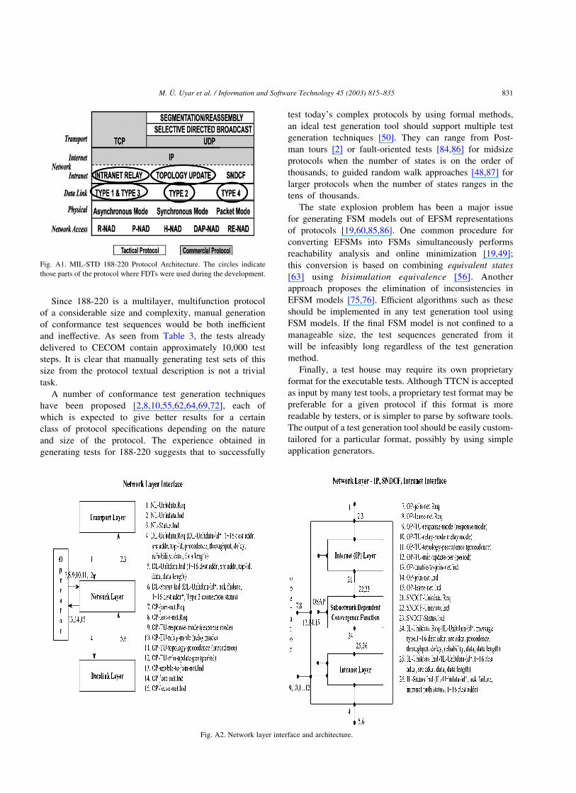
The develop an Estelle formal specification of a protocol,
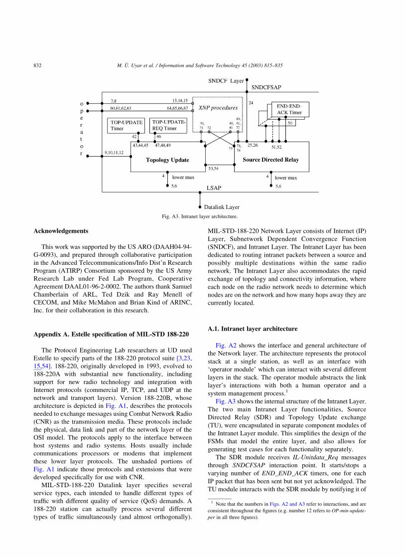
we must not only define its architecture and interface
components (e.g. as in Figs. A2 and A3 for 188-220), but we
must also carefully specify the behavior of each module of
these components. This definition, achieved through the
creation of EFSMs, is the most difficult and time-consuming
step of creating a formal specification. A syntax-directed
editor improves the readability for testers who are not FDT-
trained; it also is useful in writing non-trivial specifications.
Moreover, the modeling and specification languages, such
as SDL [38,39] and UML [58], enjoy widespread industrial
popularity, partially due to their standard graphical
representation and readily available commercial tools.
Once all states and transitions of a protocol (including
inputs and outputs) are finalized, the writing of the Estelle
code itself is fast and straightforward.Fig. 14. Estelle as part of synergistic efforts to develop C4I systems.
M. U. Uyar et al. / Information and Software Technology 45 (2003) 815–835830
Since 188-220 is a multilayer, multifunction protocol
of a considerable size and complexity, manual generation
of conformance test sequences would be both inefficient
and ineffective. As seen from Table 3, the tests already
delivered to CECOM contain approximately 10,000 test
steps. It is clear that manually generating test sets of this
size from the protocol textual description is not a trivial
task.
A number of conformance test generation techniques
have been proposed [2,8,10,55,62,64,69,72], each of
which is expected to give better results for a certain
class of protocol specifications depending on the nature
and size of the protocol. The experience obtained in
generating tests for 188-220 suggests that to successfully
test today’s complex protocols by using formal methods,
an ideal test generation tool should support multiple test
generation techniques [50]. They can range from Post-
man tours [2] or fault-oriented tests [84,86] for midsize
protocols when the number of states is on the order of
thousands, to guided random walk approaches [48,87] for
larger protocols when the number of states ranges in the
tens of thousands.
The state explosion problem has been a major issue
for generating FSM models out of EFSM representations
of protocols [19,60,85,86]. One common procedure for
converting EFSMs into FSMs simultaneously performs
reachability analysis and online minimization [19,49];
this conversion is based on combining equivalent states
[63] using bisimulation equivalence [56]. Another
approach proposes the elimination of inconsistencies in
EFSM models [75,76]. Efficient algorithms such as these
should be implemented in any test generation tool using
FSM models. If the final FSM model is not confined to a
manageable size, the test sequences generated from it
will be infeasibly long regardless of the test generation
method.
Finally, a test house may require its own proprietary
format for the executable tests. Although TTCN is accepted
as input by many test tools, a proprietary test format may be
preferable for a given protocol if this format is more
readable by testers, or is simpler to parse by software tools.
The output of a test generation tool should be easily custom-
tailored for a particular format, possibly by using simple
application generators.
Fig. A1. MIL-STD 188-220 Protocol Architecture. The circles indicate
those parts of the protocol where FDTs were used during the development.
Fig. A2. Network layer interface and architecture.
M. U. Uyar et al. / Information and Software Technology 45 (2003) 815–835 831
Acknowledgements
This work was supported by the US ARO (DAAH04-94-
G-0093), and prepared through collaborative participation
in the Advanced Telecommunications/Info Dist’n Research
Program (ATIRP) Consortium sponsored by the US Army
Research Lab under Fed Lab Program, Cooperative
Agreement DAAL01-96-2-0002. The authors thank Samuel
Chamberlain of ARL, Ted Dzik and Ray Menell of
CECOM, and Mike McMahon and Brian Kind of ARINC,
Inc. for their collaboration in this research.
Appendix A. Estelle specification of MIL-STD 188-220
The Protocol Engineering Lab researchers at UD used
Estelle to specify parts of the 188-220 protocol suite [3,23,
15,54]. 188-220, originally developed in 1993, evolved to
188-220A with substantial new functionality, including
support for new radio technology and integration with
Internet protocols (commercial IP, TCP, and UDP at the
network and transport layers). Version 188-220B, whose
architecture is depicted in Fig. A1, describes the protocols
needed to exchange messages using Combat Network Radio
(CNR) as the transmission media. These protocols include
the physical, data link and part of the network layer of the
OSI model. The protocols apply to the interface between
host systems and radio systems. Hosts usually include
communications processors or modems that implement
these lower layer protocols. The unshaded portions of
Fig. A1 indicate those protocols and extensions that were
developed specifically for use with CNR.
MIL-STD-188-220 Datalink layer specifies several
service types, each intended to handle different types of
traffic with different quality of service (QoS) demands. A
188-220 station can actually process several different
types of traffic simultaneously (and almost orthogonally).
MIL-STD-188-220 Network Layer consists of Internet (IP)
Layer, Subnetwork Dependent Convergence Function
(SNDCF), and Intranet Layer. The Intranet Layer has been
dedicated to routing intranet packets between a source and
possibly multiple destinations within the same radio
network. The Intranet Layer also accommodates the rapid
exchange of topology and connectivity information, where
each node on the radio network needs to determine which
nodes are on the network and how many hops away they are
currently located.
A.1. Intranet layer architecture
Fig. A2 shows the interface and general architecture of
the Network layer. The architecture represents the protocol
stack at a single station, as well as an interface with
‘operator module’ which can interact with several different
layers in the stack. The operator module abstracts the link
layer’s interactions with both a human operator and a
system management process.1
Fig. A3 shows the internal structure of the Intranet Layer.
The two main Intranet Layer functionalities, Source
Directed Relay (SDR) and Topology Update exchange
(TU), were encapsulated in separate component modules of
the Intranet Layer module. This simplifies the design of the
FSMs that model the entire layer, and also allows for
generating test cases for each functionality separately.
The SDR module receives IL-Unitdata_Req messages
through SNDCFSAP interaction point. It starts/stops a
varying number of END_END_ACK timers, one for each
IP packet that has been sent but not yet acknowledged. The
TU module interacts with the SDR module by notifying it of
Fig. A3. Intranet layer architecture.
1 Note that the numbers in Figs. A2 and A3 refer to interactions, and are
consistent throughout the figures (e.g. number 12 refers to OP-min-update-
per in all three figures).
M. U. Uyar et al. / Information and Software Technology 45 (2003) 815–835832

any topology changes that take place dynamically. The TU
module communicates with two timers: Topology_Update
Timer and Topology_Update_Request Timer. The former is
started after a topology update message is sent by the
station. According to 188-220A, a station is not allowed to
send another topology update message until the timer
expires. The latter performs the same role for topology
update request messages.
Both SDR and TU modules can send and receive
messages from the datalink layer through their lower_mux
interaction points-the messages from the two modules are
multiplexed by the parent Intranet Layer module. A peer
operator or management component is connected directly to
the Topology Update module and can set parameters that are
relevant in topology update mechanism. Part of the diagram
inside the dash-lined rectangular contains modules that
handle XNP procedures: joining and leaving the net with
either centralized or distributed control, and parameter
update requests.
References
[1] I. Adler, N. Megiddo, A simplex algorithm whose average number of
steps is bound between two quadratic functions of the smaller
dimension, J. ACM 32 (4) (1985) 871–895.
[2] A.V. Aho, A.T. Dahbura, D. Lee, M.U. Uyar, An optimization
technique for protocol conformance test generation based on UIO
sequences and rural Chinese postman tours, IEEE Trans. Commun. 39
(11) (1991) 1604–1615.
[3] P.D. Amer, G. Burch, A.S. Sethi, D. Zhu, T. Dzik, R. Menell, M.
McMahon, Estelle specification of MIL-STD 188-220A DLL, Proc.
IEEE MILCOM (1996).
[4] P.D. Amer, M.A. Fecko, A.S. Sethi, M.U. Uyar, A.Y. Duale, in:
A.J. Tardif, J.W. Gowens (Eds.), Formal specification and
conformance testing of Army communications protocols, ATIRP
1996–2001, U Maryland Printing Services, 2001, pp. 3.1–3.28,
invited paper.
[5] B. Baumgarten, H.-J. Burkhardt, A. Giessler (Eds.), Proceedings of
the IFIP International Workshop Testing Communication Systems
(IWTCS), Darmstadt, Germany, Kluwer, Boston, MA, 1996.
[6] A. Bhattacharyya, Checking Experiments in Sequential Machines,
Wiley, New York, 1989.
[7] J. Bi, J. Wu, in: M. Kim, S. Kang, K. Hong (Eds.), Application of a
TTCN-based conformance test environment to the Internet email
protocol, Proceedings of the IFIP International Workshop Testing
Communication Systems (IWTCS), Cheju Island, Korea, Boston,
MA, 1997, pp. 324–330.
[8] B.S. Bosik, M.U. Uyar, FSM-based formal methods in protocol
conformance testing: from theory to implementation, Comput.
Networks ISDN Syst. 22 (1) (1991) 7–34.
[9] J. Bredereke, R. Gotzhein, A theory for the derivation of tests,
Proceedings of the IFIP Formal Description Techniques (FORTE),
Chapman & Hall, London, 1985, pp. 376–378.
[10] E. Brinksma, A theory for the derivation of tests, Proceedings of the
IFIP Protocol Specification, Testing, and Verification (PSTV), North-
Holland, Amsterdam, 1988.
[11] S. Budkowski, Estelle development toolset. FDT Concepts and Tools,
(Elsevier) Comput. Networks ISDN Syst. 25 (1) (1992).
[12] S. Budkowski, A. Cavalli, E. Najm (Eds.), Proceedings of the IFIP
Joint International Conference FORTE/PSTV, Paris, France, Boston,
MA, Kluwer, Boston, MA, 1998.
[13] S. Budkowski, P. Dembinski, An introduction to Estelle: a specifica-
tion language for distributed systems, Comput. Networks ISDN Syst.
14 (1) (1991) 3–24.
[14] S. Budkowski, S. Fischer, R. Gotzhein (Eds.), Proceedings of the
International Workshop FDT Estelle, Evry, France, Evry, France:
Institut National des Telecommunications (INT), 1998.
[15] R. Burch, P. Amer, S. Chamberlain, Performance evaluation of MIL-
STD 188-220A: interoperability standard for digital message transfer
device subsystems, Proc. IEEE MILCOM, San Diego, CA November
(1995).
[16] K. Cerans, Decidability of bisimulation equivalences for parallel
timer processes, Proceedings of the CAV: International Conference
Computer-Aided Verification of LCNS, Montreal, Canada, vol. 663,
Springer, Berlin, 1992, pp. 302–315.
[17] S. Chanson, J. Zhu, A unified approach to protocol test sequence
generation, Proc. IEEE INFOCOM (1993) 1d.1.1–1d.1.9.
[18] O. Catrina, E. Lallet, S. Budkowski, Automated implementation of the
Xpress Transport Protocol (XTP) from an Estelle specification,
Electron. J. Networks Distrib. Process. 7 (1998) 3–19.
[19] K.T. Cheng, A.S. Krishnakumar, Automatic generation of functional
vectors using the extended finite state machine model, ACM Trans.
Des. Automat. Electron. Syst. 1 (1) (1996) 57–79.
[20] S.-K. Cheong, K.-H. Lee, T.-W. Jeong, in: B. Baumgarten, H.-J.
Burkhardt, A. Giessler (Eds.), The analysis of integrating test results
for ATM switching systems, Proceedings of the IFIP International
Workshop Testing Communication Systems (IWTCS), Darmstadt,
Germany, Kluwer, Boston, MA, 1996, pp. 83–89.
[21] J.Y. Choi, B.K. Hong, in: B. Baumgarten, H.-J. Burkhardt, A.
Giessler (Eds.), Generation of conformance test suites for B-ISDN
signalling relevant to multi-party testing architecuture, Proceedings
of the IFIP International Workshop Testing Communication
Systems (IWTCS), Darmstadt, Germany, Kluwer, Boston, MA,
1996, pp. 316–330.
[22] T. Cormen, C. Leiserson, R. Rivest, Introduction to Algorithms,
McGraw-Hill, London, 1996.
[23] DoD. Military standard-interoperability standard for digital message
device subsystems (MIL-STD 188-220B), 1998.
[24] R. Dssouli, K. Saleh, E. Aboulhamid, A. En-Nouaary, C. Bourhfir,
Test development for communication protocols: Towards automation,
(Elsevier) Comput. Networks 31 (1999) 1835–1872.
[25] A.Y. Duale, Feasible Test Generation by Elimination of Inconsis-
tencies in EFSM Models of Computer and Communication Systems,
PhD Dissertation, The City University of New York, NY, 2000.
[26] A. Duale, U. Uyar, in: H. Ural, R. Probert, G.v. Bochmann (Eds.),
Generation of feasible test sequences for EFSM models, Proceedings
of the IFIP International Conference on Testing of Communicating
Systems, TestCom, Ottawa, 2000, pp. 91–109.
[27] T. Dzik, M. McMahon, MIL-STD 188-220A evolution: a model fro
technical architecture standards development, Proc. IEEE MILCOM,
Monterey, CA November (1997).
[28] A. En-Nouaary, R. Dssouli, F. Khendek, A. Elqortobi, Timed test
cases generation based on state characterisation technique, Proc. IEEE
RTSS: Real-Time Syst. Symp, Madrid, Spain (1998) 220–229.
[29] M.A. Fecko, Timing and controllability issues in conformance testing
of communications protocols, PhD Dissertation, CISC Department,
University of Delaware, 1999.
[30] M.A. Fecko, P.D. Amer, A.S. Sethi, M.U. Uyar, T. Dzik, R. Menell,
M. McMahon, Formal design and testing of MIL-STD 188-220A
based on Estelle, Proc. IEEE MILCOM, Monterey, CA November
(1997).
[31] M.A. Fecko, M.U. Uyar, P.D. Amer, A.S. Sethi, Using semicontrol-
lable interfaces in testing Army communications protocols: Appli-
cation to MIL-STD 188-220B, Proc. IEEE MILCOM, Atlantic City,
NJ (1999).
[32] M.A. Fecko, M.U. Uyar, A.S. Sethi, P.D. Amer, in: S. Budkowski, A.
Cavalli, E. Najm (Eds.), Issues in Conformance testing: Multiple
semicontrollable interfaces, Proceedings of the IFIP Joint Inter-
M. U. Uyar et al. / Information and Software Technology 45 (2003) 815–835 833
national Conference FORTE/PSTV, Paris, France, Kluwer, Boston,
MA, 1998, pp. 111–126.
[33] M.A. Fecko, M.U. Uyar, A.S. Sethi, P.D. Amer, Conformance testing
in systems with semicontrollable interfaces, Ann. Telecommun. 55 (1)
(2000) 70–83.
[34] M.A. Fecko, P.D. Amer, M.U. Uyar, A.Y. Duale, in: H. Ural, R.
Probert, G.v. Bochmann (Eds.), Test generation in the presence of
conflicting timers, Proceedings of the IFIP International Con-
ference on Testing of Communicating Systems, TestCom, Ottawa,
2000.
[35] R. Gecse, in: A. Petrenko, N. Yevtushenko (Eds.), Conformance
testing methodology of Internet protocols: Internet application-layer
protocol testing-HTTP, Proceedings of the IFIP International Work-
shop Testing Communication Systems (IWTCS), Tomsk, Russia,
Kluwer, Boston, MA, 1998, pp. 35–48.
[36] T. Higashino, G. Bochmann, Automatic analysis and test case
derivation for a restricted class of LOTOS expressions with data
parameters, IEEE Trans. Software Engng 20 (1) (1994) 29–42.
[37] T. Higashino, A. Nakata, K. Taniguchi, A.R. Cavalli, Generating
test cases for a timed I/O automaton model, Proceedings of the IFIP
IWTCS: International Workshop on Testing Communication
Systems, Budapest, Hungary, Kluwer, Dordrecht, 1999, pp. 197–
214.
[38] D. Hogrefe, Validation of SDL systems, Comput. Networks ISDN
Syst. 28 (12) (1996).
[39] International Telecommunication Union, Geneva, Switzerland. ITU
Recommendation Z100: Specification and Description Language
(SDL), 1989.
[40] ISO, Information Processing Systems—OSI. ISO International
Standard 9074: Estelle—a formal description technique based on an
extended state transition model, (1989).
[41] ISO/IEC. International Standard ISO/IEC 8802-2, ANSI/IEEE Std.
802.2, second edition, 1994.
[42] A. Jirachiefpattana, R. Lai, Uncovering ISO ROSE protocol errors
using Estelle, Comput. Std Interf. 17 (5/6) (1995) 559–583.
[43] S. Kang, Y. Seo, D. Kang, M. Hong, J. Yang, I. Koh, J. Shin, S. Yoo,
M. Kim, Development and application of ATM protocol conformance
test system, Proceedings of the IFIP International Workshop Testings
of Communication Systems (IWTCS), Budapest, Hungary, 1999.
[44] T. Kato, T. Ogishi, A. Idoue, K. Suzuki, Intelligent protocol analyzer
with TCP behavior emulation for interoperability testing of TCP/IP
protocols, Proceedings of the IFIP Joint International Conference
FORTE/PSTV, Osaka, Japan (1997) 449–464.
[45] A. Khoumsi, M. Akalay, R. Dssouli, A. En-Nouaary, L. Granger, An
approach for testing real time protocol entities, Proceedings of the
IFIP TestCom: International Conference on Testing Communication
Systems, Ottawa, Canada, 2000, pp. 281–299.
[46] M. Kim, S. Kang, K. Hong (Eds.), Proceedings of the IFIP
International Workshop Testing Communication Systems (IWTCS),
Cheju Island, Korea, Boston, 1997.
[47] Z. Kohavi, Switching and Finite Automata Theory, McGraw-Hill,
New York, 1978.
[48] D. Lee, K.K. Sabnani, D.M. Kristol, S. Paul, Conformance testing of
protocols specified as communicating FSMs—a guided random walk
approach, IEEE Trans. Commun. 44 (5) (1996).
[49] D. Lee, M. Yannakakis, Online minimization of transition systems,
Proc. 24th Annu. ACM, Victoria, Canada (1992).
[50] D. Lee, M. Yannakakis, Principles and methods of testing finite state
machines—a survey, Proceedings of the IEEE 84 (8) (1996)
1090–1123.
[51] D.Y. Lee, J.Y. Lee, Test generation for the specification written in
Estelle, Proc. IFIP Protocol Specif., Test., and Verif. (PSTV),
Stockholm, Sweden June (1991).
[52] D.Y. Lee, J.Y. Lee, A well-defined Estelle specification for the
automatic test generation, IEEE Trans. Comput. 40 (4) (1991).
[53] J.K. Lenstra, A.H.G.R. Kan, On general routing problems, Networks 6
(1976) 273–280.
[54] H. Li, P. Amer, S. Chamberlain, Estelle specification of MIL-STD
188-220A: Interoperability standard for digital message transfer
device subsystems, Proceedings of the IEEE MILCOM, San Diego,
CA, November, 1995.
[55] R.E. Miller, S. Paul, On the generation of minimal-length con-
formance tests for communication protocols, IEEE/ACM Trans.
Network 2 (1) (1993) 116–129.
[56] R. Milner, Communication and Concurrency, Prentice-Hall, Engle-
wood Cliffs, NJ, 1989.
[57] C. Negulescu, E. Borcoci, in: S. Budkowski, S. Fischer, R. Gotzhein
(Eds.), SSCOP protocol throughput evaluation-simulation based on
Estelle specification, Proceedings of the International Workshop FDT
Estelle, Evry, France, Evry, France: Institut National des Telecom-
munications (INT), 1998, pp. 75–98.
[58] Object Management Group, Framingham, MA. OMG Standard:
Unified Modeling Language (UML) 1.1, 1997.
[59] A. Petrenko, N. Yevtushenko (Eds.), Proceedings of the IFIP
International Workshop Testing Communication Systems (IWTCS),
Tomsk, Russia, Kluwer, Boston, MA, 1998.
[60] D.H. Pitt, D. Freestone, The derivation of conformance tests from
LOTOS specifications, IEEE Trans. Software Engng 16 (12) (1990)
1337–1343.
[61] S. Rapps, E. Weyuker, Selecting software test data using data flow
information, IEEE Trans. Software Engng SE11 (4) (1985).
[62] J. Romijn, J. Springintveld, in: S. Budkowski, A. Cavalli, E. Najm
(Eds.), Exploiting symmetry in protocol testing, Proceedings of the
IFIP Joint International Conference FORTE/PSTV, Paris, France,
Kluwer, Boston, MA, 1998, pp. 337–351.
[63] K.K. Sabhani, A.T. Dahbura, A protocol test generation procedure,
Comput. Networks ISDN Syst. 15 (1988) 285–297.
[64] B. Sarikaya, G. von Bochmann, E. Cerny, A test design methodology
for protocol testing, IEEE Trans. Software Engng 13 (5) (1987)
518–531.
[65] J. Springintveld, F. Vaandrager, P.R. D’Argenio, Testing timed
automata, (Elsevier) Theor. Comput. Sci. 254 (1-2) (2001)
225–257.
[66] J. Templemore-Finlayson, J.I. Raffy, P. Kritzinger, S. Budkowski,
in: S. Budkowski, A. Cavalli, E. Najm (Eds.), A graphical
representation and prototype editor for the formal description
technique Estelle, Proceedings of the IFIP Joint International
Conference FORTE/PSTV, Paris, France, Kluwer, Boston, MA,
1998, pp. 37–55.
[67] R. Tenney, A tutorial introduction to Estelle. Technical Report 88-1,
University of Massachusetts, Boston, 1988
[68] J. Thees, in: S. Budkowski, S. Fischer, R. Gotzhein (Eds.), Protocol
implementation with Estelle—from prototypes to efficient implemen-
tations, Proceedings of the International Workshop FDT Estelle, Evry,
France, Evry, France: Institut National des Telecommunications
(INT), 1998, pp. 187–193.
[69] J. Tretmans, Conformance testing with labelled transitions systems:
Implementation relations and test generation, Comput. Networks and
ISDN Syst. 29 (1) (1996) 49–79.
[70] K. Turner, Formal Description Techniques, North-Holland, Amster-
dam, 1989.
[71] H. Ural, B. Yang, A test sequence selection method for protocols
specified in Estelle. Technical Report TR-88-18, University of
Ottawa, 1988.
[72] H. Ural, B. Yang, A test sequence selection method for protocol
testing, IEEE Trans. Commun. 39 (4) (1991).
[73] H. Ural, Formal methods for test sequence generation, Comput.
Commun. 15 (5) (1992) 311–325.
[74] M.U. Uyar, A.T. Dahbura, Optimal test sequence generation for
protocols: the Chinese postman algorithm applied to Q.931, Proc.
IEEE GLOBECOM (1986) 68–72.
[75] M.U. Uyar, A.Y. Duale, Modeling VHDL specifications as
consistent EFSMs, Proc. IEEE MILCOM, Monterey, CA November
(1997).
M. U. Uyar et al. / Information and Software Technology 45 (2003) 815–835834
[76] M.U. Uyar, A.Y. Duale, Removal of inconsistencies in VHDL
specifications, Proc. US Army Research Lab ATIRP Conf., College
Park, MD February (1998).
[77] M.U. Uyar, A.Y. Duale, Conformance tests for Army communication
protocols, Proc. US Army Research Lab ATIRP Conf., College Park,
MD March (2000).
[78] M.U. Uyar, M.A. Fecko, A.S. Sethi, P.D. Amer, Minimum-cost
solutions for testing protocols with timers, Proc. IEEE Int.
Performance, Comput. Commun. Conf. (IPCCC), Phoenix, AZ
(1998) 346–354.
[79] M.U. Uyar, M.A. Fecko, A.S. Sethi, P.D. Amer, Testing protocols
modeled as FSMs with timing parameters, Comput. Networks 31 (8)
(1999) 1967–1988.
[80] M.U. Uyar, M.H. Sherif, Protocol modeling for conformance testing:
Case study for the ISDN LAPD protocol, AT&T Tech. J. 69 (1) (1990).
[81] M.U. Uyar, A.Y. Duale, Modeling VHDL Specifications as Consistent
EFSMs, Proc. IEEE MILCOM, Monterey, CA (1997) 740–744.
[82] M.U. Uyar, A.Y. Duale, Resolving inconsistencies in VHDL specifica-
tions, Proc. IEEE MILCOM, Atlantic City, NJ 5.1.3 (1999) 513.
[83] E. Vazquez, P. Sandoval, M. Sedano, J. Vinyes, Automatic
implementation of TP4/IP with an Estelle workstation-development
methodology and performance evaluation, Proceedings of the IFIP
Protocol Specification, Testing, and Verification (PSTV), North-
Holland, Amsterdam, 1992, pp. 125–139.
[84] G. von Bochmann, A. Das, R. Dssouli, M. Dubuc, A. Ghedamsi, G.
Luo, Fault Models in Testing, Proceedings of the IFIP International
Workshop Protocol Test Systems (IWPTS), North-Holland, Amster-
dam, 1992, pp. 17–31.
[85] C.J. Wang, M.T. Liu, Axiomatic test sequence generation for
extended finite state machines, Proc. 12th Conf Distrib. Comput.
Syst. (1992) 252–259.
[86] C.J. Wang, M.T. Liu, Generating test cases for EFSM with given fault
models, Proc. IEEE INFOCOM (1993) 774–781.
[87] C. West, Protocol validation by random state exploration, Proceedings
of the IFIP Protocol Specification, Testing, and Verification (PSTV),
North-Holland, Amsterdam, 1986.
[88] For details on Estelle specification of MIL-STD 188-220, consult
http://www.cis.udel.edu/~amer/CECOM/.
[89] J. Wytrebowicz, P. Rolinski, in: S. Budkowski, S. Fischer, R.
Gotzhein (Eds.), Analysis tools for Estelle specifications, Proceedings
of the International Workshop FDT Estelle, Evry, France, Evry,
France: Institut National des Telecommunications (INT), 1998, pp.
141–155.
[90] S. Yoo, L. Collica, M. Kim, in: B. Baumgarten, H.-J. Burkhardt, A.
Giessler (Eds.), Conformance testing of ATM Adaptation Layer
protocol, Proceedings of the IFIP International Workshop Testing
Communication Systems (IWTCS), Darmstadt, Germany, Kluwer,
Boston, MA, 1996, pp. 237–252.
M. U. Uyar et al. / Information and Software Technology 45 (2003) 815–835 835
Related Documents


