www.walworth.com EXPANDING GATE VALVE CATALOG

Welcome message from author
This document is posted to help you gain knowledge. Please leave a comment to let me know what you think about it! Share it to your friends and learn new things together.
Transcript
www.walworth.com
EXPANDING GATE VALVE
CATALOG
WA
LWO
RTH
- EXPAN
DIN
G G
ATE VALVE

www.walworth.com 3
INDEXINTRODUCTION
WALWORTH MISSION & VISION ............................................................................................................................................................................4WALWORTH ENGINEERING CONTROL ................................................................................................................................................................5WALWORTH QUALITY SYSTEM .............................................................................................................................................................................5QUALITY CONTROL EQUIPMENT ..........................................................................................................................................................................9
DESIGN FEATURES
THROUGH CONDUIT RISING STEM DESIGN EXPANDING GATE VALVES ...................................................................................................... 11DISC CONFIGURATION ........................................................................................................................................................................................12FULL OPENING THROUGH CONDUIT DESIGN .................................................................................................................................................12OPERATION DESIGN, VALVE POSITIONS ..........................................................................................................................................................13CONTROL ARM OPERATION ...............................................................................................................................................................................14VENTING SYSTEMS ON BONNET .......................................................................................................................................................................15SEAL SYSTEM ON PACKING CHAMBER ...........................................................................................................................................................16DRAIN OF THE VALVE .........................................................................................................................................................................................16EMERGENCY SEALANT INJECTOR ON PACKING CHAMBER .........................................................................................................................17SEATS ARRANGEMENT .......................................................................................................................................................................................17EMERGENCY SEALANT INJECTOR SYSTEM ON SEAT RINGS .......................................................................................................................18BYPASS .................................................................................................................................................................................................................18DOUBLE BLOCK & BLEED DESIGN (DBB) ........................................................................................................................................................19BIDIRECTIONAL SEATS .......................................................................................................................................................................................19DOUBLE ISOLATION AND BLEED DIB-1 (Both seats bi-directional) ..............................................................................................................19FINITE ELEMENT ANALYSIS AND COMPUTER-ASSISTED DESIGN ...............................................................................................................20
SLAB GATE VALVES
SOFT SEAT-METAL SEAT EXPANDING GATE VALVE ........................................................................................................................................22METAl to METAL SEAT EXPANDING GATE VALVE ............................................................................................................................................23EXPANDING GATE VALVE CLASS 150 ................................................................................................................................................................24EXPANDING GATE VALVE CLASS 300 ................................................................................................................................................................28EXPANDING GATE VALVE CLASS 600 ................................................................................................................................................................32EXPANDING GATE VALVE CLASS 900 ................................................................................................................................................................36EXPANDING GATE VALVE CLASS 1500 ..............................................................................................................................................................39MOST COMMON TRIM ARRANGEMENTS ...........................................................................................................................................................42API 6D THROUGH CONDUITS EXPANDING GATE VALVE (SOFT SEAT), OPERATOR SIZING REQUIREMENTS ......................................44
TECHNICAL INFORMATION
TYPES OF END CONNECTIONS ...........................................................................................................................................................................47TYPE OF OPERATORS .........................................................................................................................................................................................48LOCKING DEVICE .................................................................................................................................................................................................48PRESSURE-TEMPERATURE RATINGS ..............................................................................................................................................................49DESIGN BASIS ......................................................................................................................................................................................................52HOW TO ORDER ...................................................................................................................................................................................................53GENERAL TERMS AND CONDITIONS ................................................................................................................................................................54
6D-0097
www.walworth.com4
WALWORTH
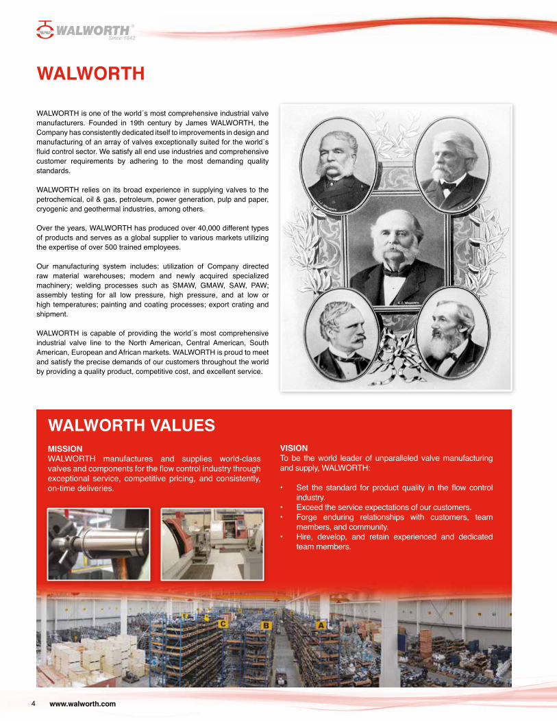
WALWORTH is one of the world´s most comprehensive industrial valve manufacturers. Founded in 19th century by James WALWORTH, the Company has consistently dedicated itself to improvements in design and manufacturing of an array of valves exceptionally suited for the world´s fluid control sector. We satisfy all end use industries and comprehensive customer requirements by adhering to the most demanding quality standards.
WALWORTH relies on its broad experience in supplying valves to the petrochemical, oil & gas, petroleum, power generation, pulp and paper, cryogenic and geothermal industries, among others.
Over the years, WALWORTH has produced over 40,000 different types of products and serves as a global supplier to various markets utilizing the expertise of over 500 trained employees.
Our manufacturing system includes: utilization of Company directed raw material warehouses; modern and newly acquired specialized machinery; welding processes such as SMAW, GMAW, SAW, PAW; assembly testing for all low pressure, high pressure, and at low or high temperatures; painting and coating processes; export crating and shipment.
WALWORTH is capable of providing the world´s most comprehensive industrial valve line to the North American, Central American, South American, European and African markets. WALWORTH is proud to meet and satisfy the precise demands of our customers throughout the world by providing a quality product, competitive cost, and excellent service.
WALWORTH VALUESMISSIONWALWORTH manufactures and supplies world-class valves and components for the flow control industry through exceptional service, competitive pricing, and consistently, on-time deliveries.
VISIONTo be the world leader of unparalleled valve manufacturing and supply, WALWORTH:
• Set the standard for product quality in the flow control industry.
• Exceed the service expectations of our customers.• Forge enduring relationships with customers, team
members, and community.• Hire, develop, and retain experienced and dedicated
team members.
www.walworth.com 5
WALWORTH ENGINEERING CONTROL
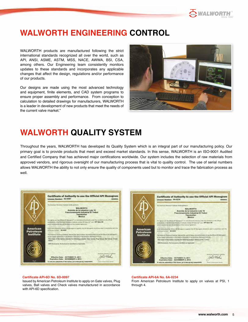
WALWORTH products are manufactured following the strict international standards recognized all over the world, such as API, ANSI, ASME, ASTM, MSS, NACE, AWWA, BSI, CSA, among others. Our Engineering team consistently monitors updates to these standards and incorporates any applicable changes that affect the design, regulations and/or performance of our products.
Our designs are made using the most advanced technology and equipment, finite elements, and CAD system programs to ensure proper assembly and performance. From conception to calculation to detailed drawings for manufacturers, WALWORTH is a leader in development of new products that meet the needs of the current valve market.”
WALWORTH QUALITY SYSTEMThroughout the years, WALWORTH has developed its Quality System which is an integral part of our manufacturing policy. Our primary goal is to provide products that meet and exceed market standards. In this sense, WALWORTH is an ISO-9001 Audited and Certified Company that has achieved major certifications worldwide. Our system includes the selection of raw materials from approved vendors, and rigorous oversight of our manufacturing process that is vital to quality control. The use of serial numbers allows WALWORTH the ability to not only ensure the quality of components used but to monitor and trace the fabrication process as well.
Certificate API-6D No. 6D-0097Issued by American Petroleum Institute to apply on Gate valves, Plug valves, Ball valves and Check valves manufactured in accordance with API-6D specification.
Certificate API-6A No. 6A-0234From American Petroleum Institute to apply on valves at PSI, 1 through 4.
www.walworth.com6
Certificate API-594 No. 594-0007Issued by American PetroleumInstitute to apply on Check Valves-Type A; Check Valves Type B manufactured in accordance with API-594 specification.
API-600 Certificate No. 600-0109Issued by American Petroleum Institute to apply on Bolted Bonnet Steel Gate Valves manufactured in accordance with API-600 specification.
API-602 Certificate No. 602-0024Issued by American Petroleum Institute to apply on Compact Steel Gate Valves, Compact Steel Globe Valves, and Compact Steel Check Valves manufactured in accordance with API-602 specification.
Certificate as per PED 97/23/EC Module H To stamp CE products.
Certificate ISO-9001 No. 0038Issued by American Petroleum Institute since April 1999.
www.walworth.com 7
Emissions after 500 cycles at ambient and 350 °FIssued by Yarmouth Research and Technology Lab for 3 inch Class 300 Gate Valve After 500 cycles the measurement result was less than 50 ppm.
Emissions after 500 cycles at ambient and 350 °FIssued by Yarmouth Research and Technology Lab for 8 inch Class 300 Gate Valve After 500 cycles the measurement result was less than 50 ppm.
Emissions after 500 cycles at ambient and 350 °FIssued by Yarmouth Research and Technology Lab for 16 inch Class 150 Gate Valve After 500 cycles the measurement result was less than 50 ppm.
Certificate NMX-CC-9001 (Mexican Standards ISO-9001) No. 0552/2007 Issued by PEMEX in accordance with ISO-9001 Quality Assurance System.
Supplier Qualification Certificate NO. 279/13 Issued by the Equipment and Materials Testing Laboratory, CFE (LAPEM in Spanish)
PRODUCT CERTIFICATIONS
www.walworth.com8
TÜV Rheinland Certificate No. TRASA 700-13-0019API-6D Trunnion mounted bolted body ball valves, carbon steel (A105-WCB) construction, double block and bleed service, primarily used but not limited to the oil and gas standard and severe applications.
Certificates of Ultra Low Fugitive Emissions No. 20985-3, 8 & 16 in accordance with ISO-15848-1 “Industrial Valves”Measurement, Test and Qualification Procedures for Fugitive Emissions “Part 1: Classification System and Qualification Procedures for Type Testing of Valves”.
Fire Test Certificate No. 01-1/05In accordance with API-6FA and API Standard API-607 for Trunnion Ball Valves in accordance with API-6D.
TA Luft Certificate (Fugitive Emission) ApprovalISO-5211 Top Flange, Anti-Static Device.
www.walworth.com 9
QUALITY CONTROL EQUIPMENT In order to assure that WALWORTH products comply with international quality standards, in-house equipment is kept for monitoring control. Some of this equipment includes:
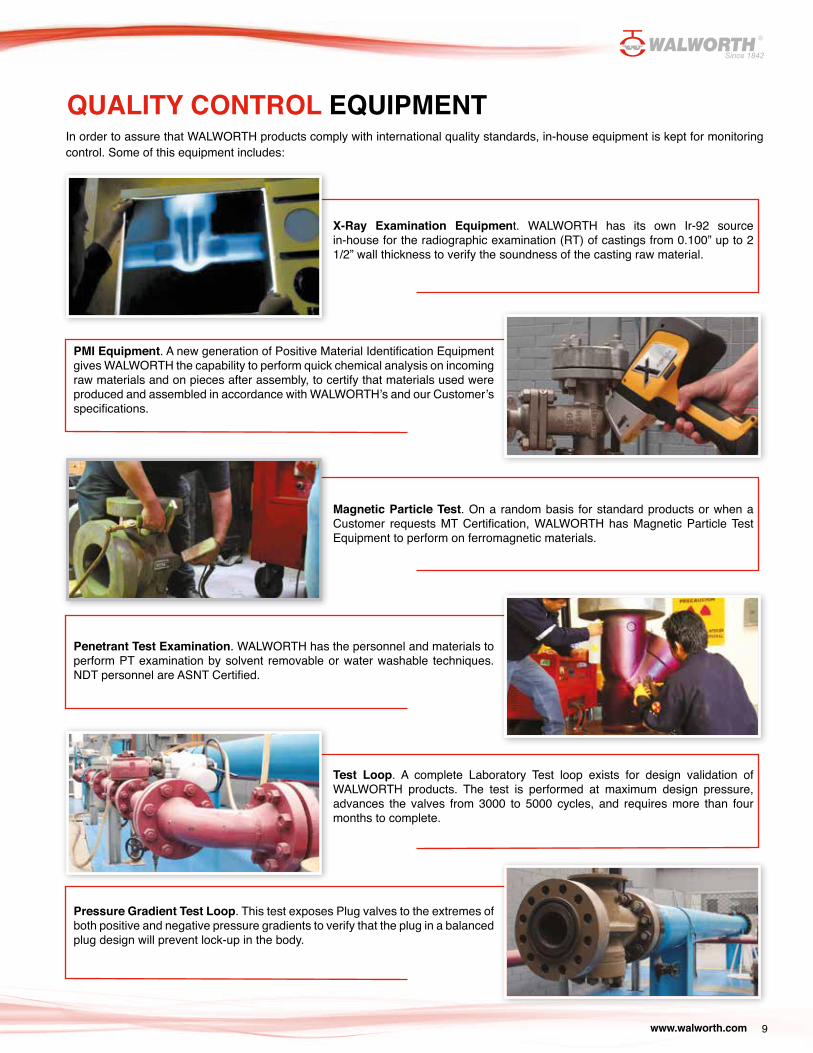
X-Ray Examination Equipment. WALWORTH has its own Ir-92 source in-house for the radiographic examination (RT) of castings from 0.100” up to 2 1/2” wall thickness to verify the soundness of the casting raw material.
Magnetic Particle Test. On a random basis for standard products or when a Customer requests MT Certification, WALWORTH has Magnetic Particle Test Equipment to perform on ferromagnetic materials.
Test Loop. A complete Laboratory Test loop exists for design validation of WALWORTH products. The test is performed at maximum design pressure, advances the valves from 3000 to 5000 cycles, and requires more than four months to complete.
PMI Equipment. A new generation of Positive Material Identification Equipment gives WALWORTH the capability to perform quick chemical analysis on incoming raw materials and on pieces after assembly, to certify that materials used were produced and assembled in accordance with WALWORTH’s and our Customer’s specifications.
Penetrant Test Examination. WALWORTH has the personnel and materials to perform PT examination by solvent removable or water washable techniques. NDT personnel are ASNT Certified.
Pressure Gradient Test Loop. This test exposes Plug valves to the extremes of both positive and negative pressure gradients to verify that the plug in a balanced plug design will prevent lock-up in the body.
www.walworth.com10
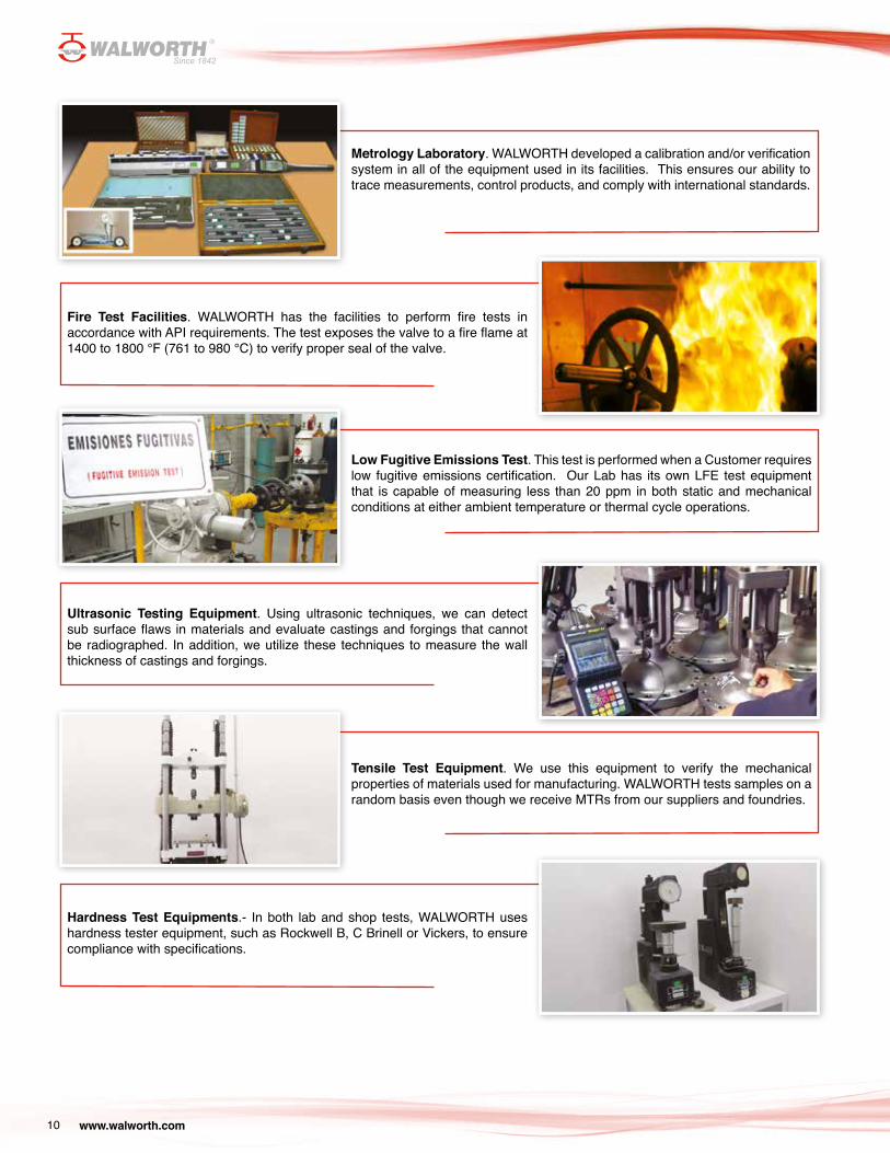
Metrology Laboratory. WALWORTH developed a calibration and/or verification system in all of the equipment used in its facilities. This ensures our ability to trace measurements, control products, and comply with international standards.
Low Fugitive Emissions Test. This test is performed when a Customer requires low fugitive emissions certification. Our Lab has its own LFE test equipment that is capable of measuring less than 20 ppm in both static and mechanical conditions at either ambient temperature or thermal cycle operations.
Tensile Test Equipment. We use this equipment to verify the mechanical properties of materials used for manufacturing. WALWORTH tests samples on a random basis even though we receive MTRs from our suppliers and foundries.
Fire Test Facilities. WALWORTH has the facilities to perform fire tests in accordance with API requirements. The test exposes the valve to a fire flame at 1400 to 1800 °F (761 to 980 °C) to verify proper seal of the valve.
Ultrasonic Testing Equipment. Using ultrasonic techniques, we can detect sub surface flaws in materials and evaluate castings and forgings that cannot be radiographed. In addition, we utilize these techniques to measure the wall thickness of castings and forgings.
Hardness Test Equipments.- In both lab and shop tests, WALWORTH uses hardness tester equipment, such as Rockwell B, C Brinell or Vickers, to ensure compliance with specifications.
www.walworth.com 11
WALWORTH offers this product line in the following base materials.
a) Carbon steel as per ASTM A216 grades WCB, WCC.b) Carbon steel for NACE applications as per ASTM A216
grade WCB with 0.25% maximum and 22 HRc maximum hardness. CE= 0.43% maximum.
FULL OPENING THROUGH CONDUIT DESIGN: WALWORTH Expanding Gate valves allows the pipeline fluids to flow freely with a minimum of turbulence. In open position, obturator allows the running of pigs, scrapers, wipers or hot tap cutters through the pipeline with no danger or damage to the internal mechanical components of the valve. Full-flow design keeps line scrapers from becoming stuck into the valve’s bore and prevents metal cuttings from jamming moving parts. Circular bore as per API-6D table 1.
EASY FIELD MAINTENANCE: Even with its sophistication, the WALWORTH Expanding Gate Valve can be completely overhauled without removal from the line. The seats of the valve can be removed, serviced and/or replaced with the valve installed.
ENERGIZED SEAT FOR POSITIVE SEALING: When the obturator is in the closed position, the seats (one on each side of the gate and segment) are energized to have a tight seal upstream and downstream. The valve seats have a nylon or RPTFE (Reinforced PolyTetraFluoroEtlylene) circular insert on their sealing faces. Two elastomer O-rings on the peripherical surfaces of the seats prevent the fluid passing through the seats when the valve is expanded due to pressure. In this way, the sealing action of the O-rings actually increases with fluid pressure. There are also metal to metal options upon request.
NO LUBRICATION NEEDED: The WALWORTH Expanding Gate Valve does not require lubrication for normal operation. However, if a sealing member becomes to be damage, a sealant can be injected into seat rings sealing areas waiting for future repairs.
PACKING CHAMBER: Chevron style packingis installed to seal the packing chamber. A lantern ring with two secondary viton O’rings are also included arround a lantern ring.
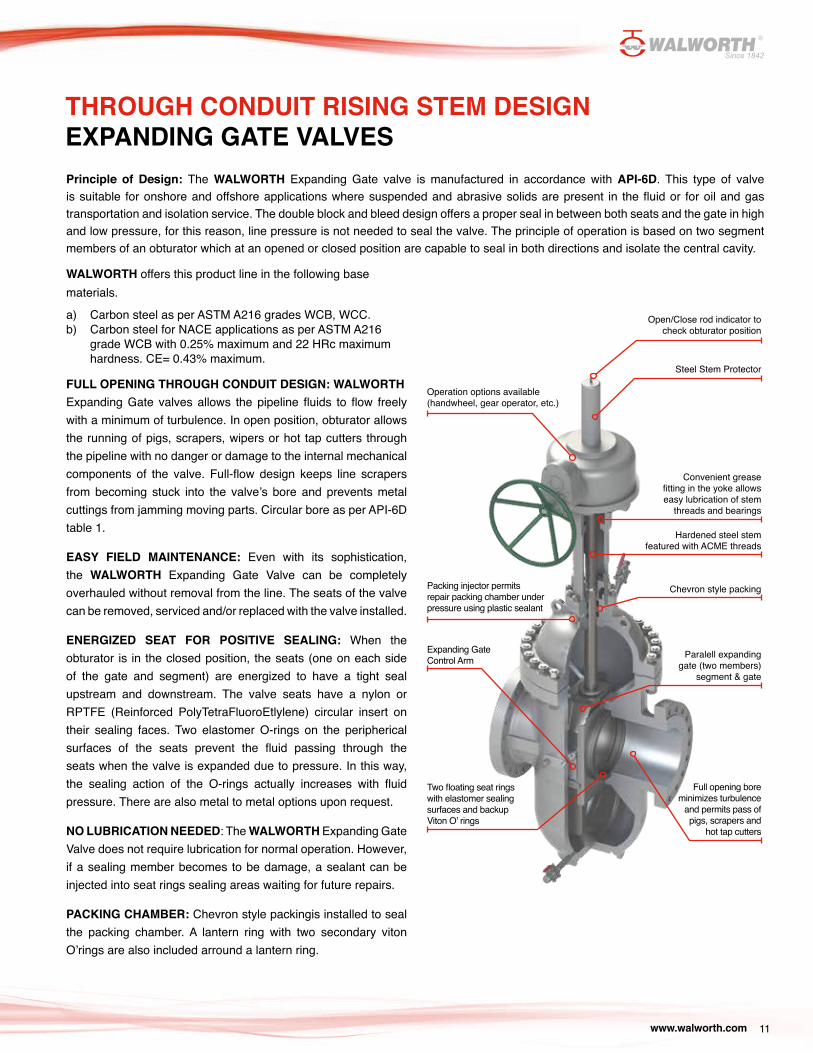
THROUGH CONDUIT RISING STEM DESIGN EXPANDING GATE VALVESPrinciple of Design: The WALWORTH Expanding Gate valve is manufactured in accordance with API-6D. This type of valve is suitable for onshore and offshore applications where suspended and abrasive solids are present in the fluid or for oil and gas transportation and isolation service. The double block and bleed design offers a proper seal in between both seats and the gate in high and low pressure, for this reason, line pressure is not needed to seal the valve. The principle of operation is based on two segment members of an obturator which at an opened or closed position are capable to seal in both directions and isolate the central cavity.
Open/Close rod indicator to check obturator position
Steel Stem Protector
Convenient grease fitting in the yoke allows easy lubrication of stem
threads and bearings
Operation options available (handwheel, gear operator, etc.)
Hardened steel stem featured with ACME threads
Packing injector permits repair packing chamber under pressure using plastic sealant
Chevron style packing
Full opening bore minimizes turbulence
and permits pass of pigs, scrapers and
hot tap cutters
Expanding Gate Control Arm
Two floating seat rings with elastomer sealing surfaces and backup Viton O’ rings
Paralell expanding gate (two members)
segment & gate
www.walworth.com12
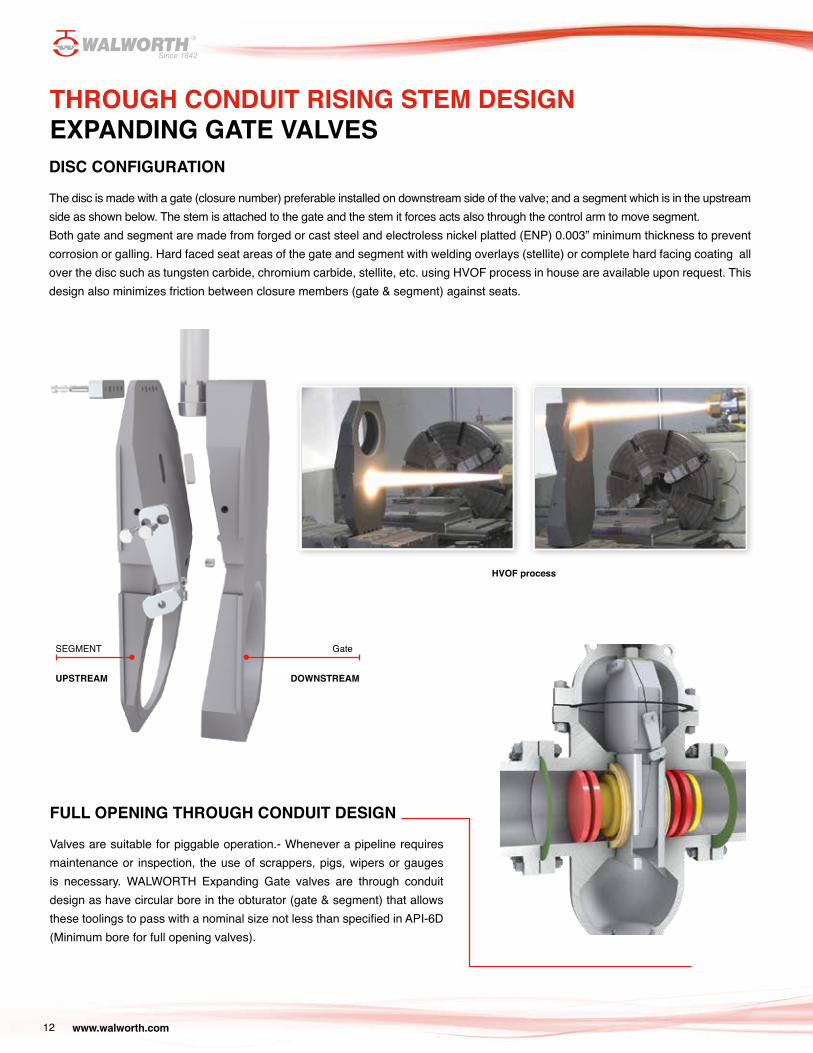
GateSEGMENT
UPSTREAM DOWNSTREAM
THROUGH CONDUIT RISING STEM DESIGN EXPANDING GATE VALVESDISC CONFIGURATION
The disc is made with a gate (closure number) preferable installed on downstream side of the valve; and a segment which is in the upstream side as shown below. The stem is attached to the gate and the stem it forces acts also through the control arm to move segment.Both gate and segment are made from forged or cast steel and electroless nickel platted (ENP) 0.003” minimum thickness to prevent corrosion or galling. Hard faced seat areas of the gate and segment with welding overlays (stellite) or complete hard facing coating all over the disc such as tungsten carbide, chromium carbide, stellite, etc. using HVOF process in house are available upon request. This design also minimizes friction between closure members (gate & segment) against seats.
FULL OPENING THROUGH CONDUIT DESIGN
Valves are suitable for piggable operation.- Whenever a pipeline requires maintenance or inspection, the use of scrappers, pigs, wipers or gauges is necessary. WALWORTH Expanding Gate valves are through conduit design as have circular bore in the obturator (gate & segment) that allows these toolings to pass with a nominal size not less than specified in API-6D (Minimum bore for full opening valves).
HVOF process
www.walworth.com 13
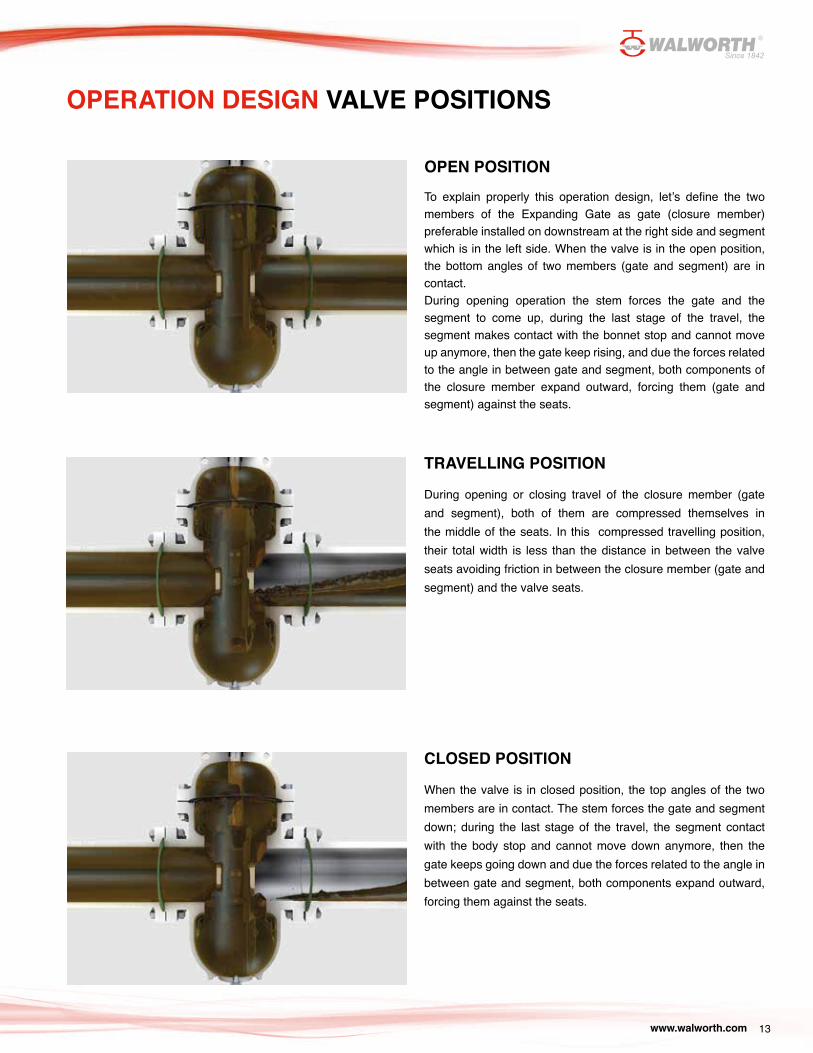
OPEN POSITIONTo explain properly this operation design, let’s define the two members of the Expanding Gate as gate (closure member) preferable installed on downstream at the right side and segment which is in the left side. When the valve is in the open position, the bottom angles of two members (gate and segment) are in contact. During opening operation the stem forces the gate and the segment to come up, during the last stage of the travel, the segment makes contact with the bonnet stop and cannot move up anymore, then the gate keep rising, and due the forces related to the angle in between gate and segment, both components of the closure member expand outward, forcing them (gate and segment) against the seats.
TRAVELLING POSITION
During opening or closing travel of the closure member (gate and segment), both of them are compressed themselves in the middle of the seats. In this compressed travelling position, their total width is less than the distance in between the valve seats avoiding friction in between the closure member (gate and segment) and the valve seats.
CLOSED POSITION
When the valve is in closed position, the top angles of the two members are in contact. The stem forces the gate and segment down; during the last stage of the travel, the segment contact with the body stop and cannot move down anymore, then the gate keeps going down and due the forces related to the angle in between gate and segment, both components expand outward, forcing them against the seats.
OPERATION DESIGN VALVE POSITIONS
www.walworth.com14
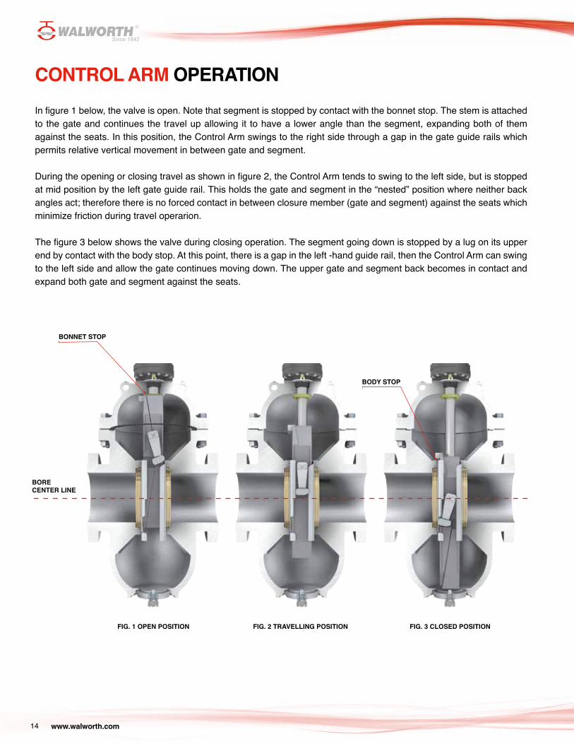
CONTROL ARM OPERATIONIn figure 1 below, the valve is open. Note that segment is stopped by contact with the bonnet stop. The stem is attached to the gate and continues the travel up allowing it to have a lower angle than the segment, expanding both of them against the seats. In this position, the Control Arm swings to the right side through a gap in the gate guide rails which permits relative vertical movement in between gate and segment.
During the opening or closing travel as shown in figure 2, the Control Arm tends to swing to the left side, but is stopped at mid position by the left gate guide rail. This holds the gate and segment in the “nested” position where neither back angles act; therefore there is no forced contact in between closure member (gate and segment) against the seats which minimize friction during travel operarion.
The figure 3 below shows the valve during closing operation. The segment going down is stopped by a lug on its upper end by contact with the body stop. At this point, there is a gap in the left -hand guide rail, then the Control Arm can swing to the left side and allow the gate continues moving down. The upper gate and segment back becomes in contact and expand both gate and segment against the seats.
FIG. 1 OPEN POSITION FIG. 2 TRAVELLING POSITION FIG. 3 CLOSED POSITION
BONNET STOP
BODY STOP
BORE CENTER LINE

www.walworth.com 15
EXPANDING GATE VALVE DESIGN FEATURESVENTING SYSTEMS ON BONNET
A feature is installed on bonnet to check if body-bonnet cavity retain pressure. A special vent plug is installed on top of the bonnet and allen screw is fitted inside this vent plug. In order to eliminate over pressure inside body-bonnet cavity unscrew lightly the allen screw until fluid come out through the lateral holes located aside the plug; this is a safety way to eliminate overpressure and avoid any injury to the personnel.
Upon request, relief ball check valve can be installed on bonnet instead the plug (venting system) to protect the valve in case of over pressure deriving this pressure to another pipeline.

www.walworth.com16
EXPANDING GATE VALVE DESIGN FEATURESSEAL SYSTEM ON PACKING CHAMBER
Packing chamber is provided with chevron style packing made from graphite. PTFE or other materials are available upon request. A lantern ring with two viton O’rings are also included as a secondary seal
O’ringsPacking
DRAIN OF THE VALVE
Due to the type of service of the Expanding Gate Valve, after a period of time the valve accumulates slurries in the bottom of the body where the obturator is allocated in closed position. To clean this area, the valve is provided with a plug for drain purposes. Floating ball valve can be installed instead a plug upon request.
www.walworth.com 17
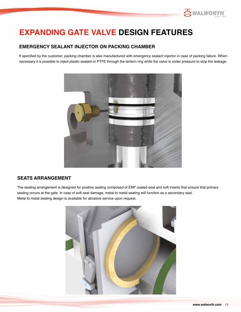
EMERGENCY SEALANT INJECTOR ON PACKING CHAMBER
If specified by the customer, packing chamber is also manufactured with emergency sealant injector in case of packing failure. When necessary it is possible to inject plastic sealant or PTFE through the lantern ring while the valve is under pressure to stop the leakage.
EXPANDING GATE VALVE DESIGN FEATURES
SEATS ARRANGEMENT
The seating arrangement is designed for positive sealing composed of ENP coated seat and soft inserts that ensure that primary sealing occurs at the gate. In case of soft seat damage, metal to metal seating will function as a secondary seal.Metal to metal seating design is available for abrasive service upon request.
www.walworth.com18
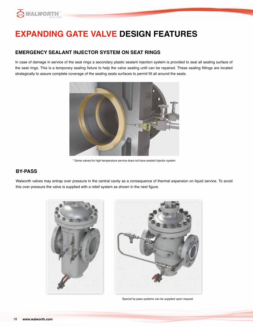
BY-PASS
Walworth valves may entrap over pressure in the central cavity as a consequence of thermal expansion on liquid service. To avoid this over pressure the valve is supplied with a relief system as shown in the next figure.
EXPANDING GATE VALVE DESIGN FEATURES
EMERGENCY SEALANT INJECTOR SYSTEM ON SEAT RINGS
In case of damage in service of the seat rings a secondary plastic sealant injection system is provided to seal all sealing surface of the seat rings. This is a temporary sealing fixture to help the valve sealing until can be repaired. These sealing fittings are located strategically to assure complete coverage of the sealing seats surfaces to permit fill all around the seats.
* Some valves for high temperature service does not have sealant injector system
Special by-pass systems can be supplied upon request.
www.walworth.com 19
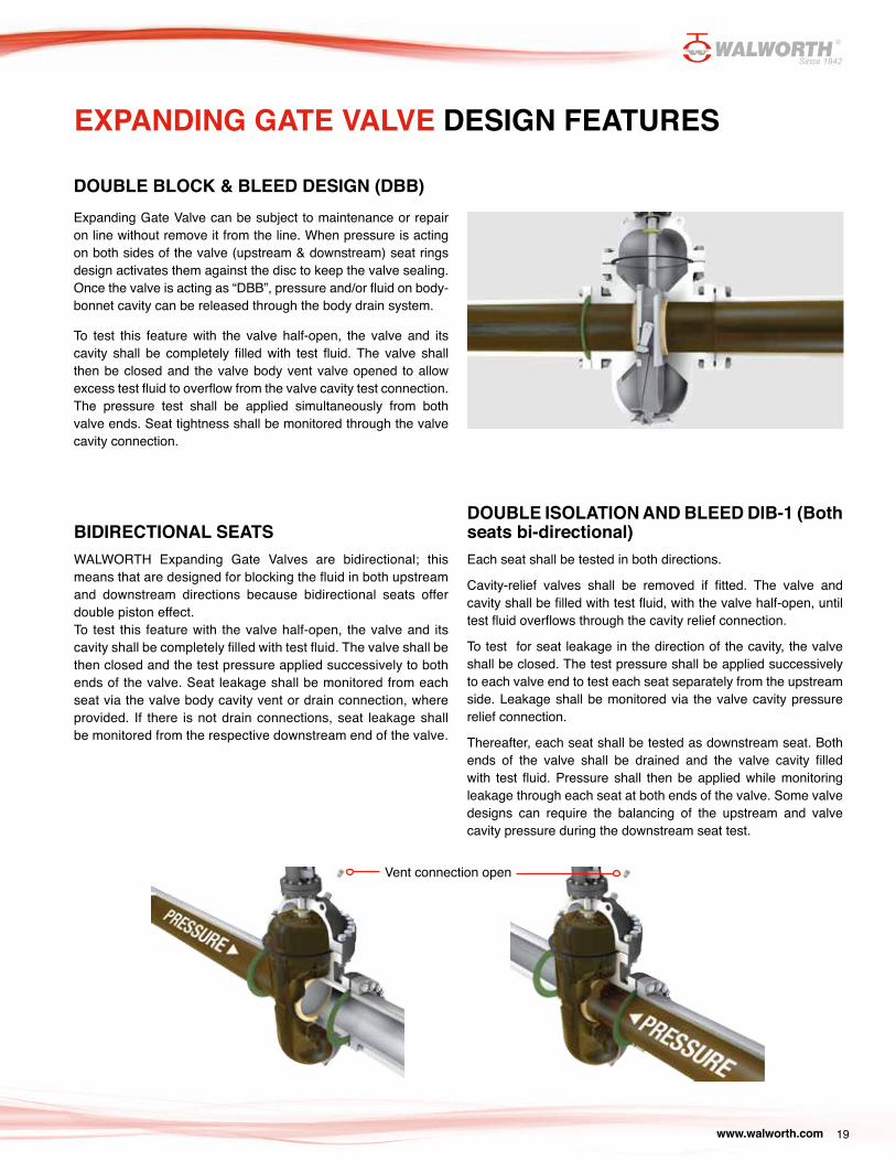
DOUBLE BLOCK & BLEED DESIGN (DBB)Expanding Gate Valve can be subject to maintenance or repair on line without remove it from the line. When pressure is acting on both sides of the valve (upstream & downstream) seat rings design activates them against the disc to keep the valve sealing. Once the valve is acting as “DBB”, pressure and/or fluid on body-bonnet cavity can be released through the body drain system.
To test this feature with the valve half-open, the valve and its cavity shall be completely filled with test fluid. The valve shall then be closed and the valve body vent valve opened to allow excess test fluid to overflow from the valve cavity test connection. The pressure test shall be applied simultaneously from both valve ends. Seat tightness shall be monitored through the valve cavity connection.
EXPANDING GATE VALVE DESIGN FEATURES
BIDIRECTIONAL SEATSWALWORTH Expanding Gate Valves are bidirectional; this means that are designed for blocking the fluid in both upstream and downstream directions because bidirectional seats offer double piston effect.To test this feature with the valve half-open, the valve and its cavity shall be completely filled with test fluid. The valve shall be then closed and the test pressure applied successively to both ends of the valve. Seat leakage shall be monitored from each seat via the valve body cavity vent or drain connection, where provided. If there is not drain connections, seat leakage shall be monitored from the respective downstream end of the valve.
DOUBLE ISOLATION AND BLEED DIB-1 (Both seats bi-directional)Each seat shall be tested in both directions.
Cavity-relief valves shall be removed if fitted. The valve and cavity shall be filled with test fluid, with the valve half-open, until test fluid overflows through the cavity relief connection.
To test for seat leakage in the direction of the cavity, the valve shall be closed. The test pressure shall be applied successively to each valve end to test each seat separately from the upstream side. Leakage shall be monitored via the valve cavity pressure relief connection.
Thereafter, each seat shall be tested as downstream seat. Both ends of the valve shall be drained and the valve cavity filled with test fluid. Pressure shall then be applied while monitoring leakage through each seat at both ends of the valve. Some valve designs can require the balancing of the upstream and valve cavity pressure during the downstream seat test.
Vent connection open
www.walworth.com20
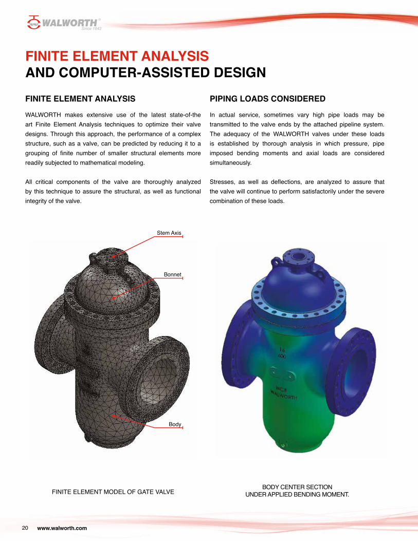
FINITE ELEMENT ANALYSIS
WALWORTH makes extensive use of the latest state-of-the art Finite Element Analysis techniques to optimize their valve designs. Through this approach, the performance of a complex structure, such as a valve, can be predicted by reducing it to a grouping of finite number of smaller structural elements more readily subjected to mathematical modeling.
All critical components of the valve are thoroughly analyzed by this technique to assure the structural, as well as functional integrity of the valve.
FINITE ELEMENT MODEL OF GATE VALVE
PIPING LOADS CONSIDERED
In actual service, sometimes vary high pipe loads may be transmitted to the valve ends by the attached pipeline system. The adequacy of the WALWORTH valves under these loads is established by thorough analysis in which pressure, pipe imposed bending moments and axial loads are considered simultaneously.
Stresses, as well as deflections, are analyzed to assure that the valve will continue to perform satisfactorily under the severe combination of these loads.
BODY CENTER SECTION UNDER APPLIED BENDING MOMENT.
FINITE ELEMENT ANALYSIS AND COMPUTER-ASSISTED DESIGN
Stem Axis
Bonnet
Body
www.walworth.com 21
FINITE ELEMENT ANALYSIS AND COMPUTER-ASSISTED DESIGN
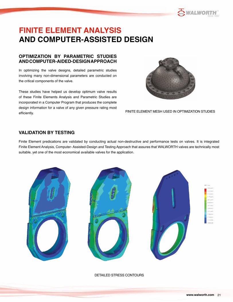
OPTIMIZATION BY PARAMETRIC STUDIES AND COMPUTER-AIDED-DESIGN APPROACH
In optimizing the valve designs, detailed parametric studies involving many non-dimensional parameters are conducted on the critical components of the valve.
These studies have helped us develop optimum valve results of these Finite Elements Analysis and Parametric Studies are incorporated in a Computer Program that produces the complete design information for a valve of any given pressure rating most efficiently.
VALIDATION BY TESTING
Finite Element predications are validated by conducting actual non-destructive and performance tests on valves. It is integrated Finite Element Analysis, Computer- Assisted-Design and Testing Approach that assures that WALWORTH valves are technically most suitable, yet one of the most economical available valves for the application.
FINITE ELEMENT MESH USED IN OPTIMIZATION STUDIES
DETAILED STRESS CONTOURS
www.walworth.com22
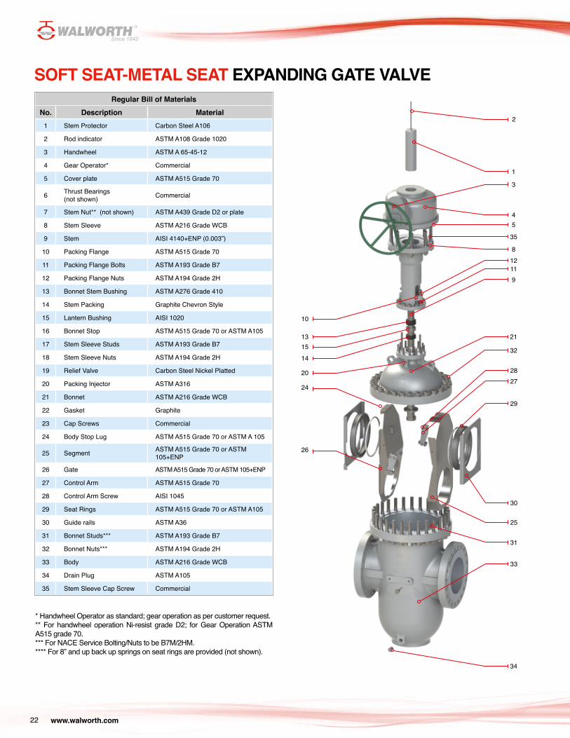
SOFT SEAT-METAL SEAT EXPANDING GATE VALVERegular Bill of Materials
No. Description Material1 Stem Protector Carbon Steel A106
2 Rod indicator ASTM A108 Grade 1020
3 Handwheel ASTM A 65-45-12
4 Gear Operator* Commercial
5 Cover plate ASTM A515 Grade 70
6 Thrust Bearings (not shown) Commercial
7 Stem Nut** (not shown) ASTM A439 Grade D2 or plate
8 Stem Sleeve ASTM A216 Grade WCB
9 Stem AISI 4140+ENP (0.003”)
10 Packing Flange ASTM A515 Grade 70
11 Packing Flange Bolts ASTM A193 Grade B7
12 Packing Flange Nuts ASTM A194 Grade 2H
13 Bonnet Stem Bushing ASTM A276 Grade 410
14 Stem Packing Graphite Chevron Style
15 Lantern Bushing AISI 1020
16 Bonnet Stop ASTM A515 Grade 70 or ASTM A105
17 Stem Sleeve Studs ASTM A193 Grade B7
18 Stem Sleeve Nuts ASTM A194 Grade 2H
19 Relief Valve Carbon Steel Nickel Platted
20 Packing Injector ASTM A316
21 Bonnet ASTM A216 Grade WCB
22 Gasket Graphite
23 Cap Screws Commercial
24 Body Stop Lug ASTM A515 Grade 70 or ASTM A 105
25 Segment ASTM A515 Grade 70 or ASTM 105+ENP
26 Gate ASTM A515 Grade 70 or ASTM 105+ENP
27 Control Arm ASTM A515 Grade 70
28 Control Arm Screw AISI 1045
29 Seat Rings ASTM A515 Grade 70 or ASTM A105
30 Guide rails ASTM A36
31 Bonnet Studs*** ASTM A193 Grade B7
32 Bonnet Nuts*** ASTM A194 Grade 2H
33 Body ASTM A216 Grade WCB
34 Drain Plug ASTM A105
35 Stem Sleeve Cap Screw Commercial
* Handwheel Operator as standard; gear operation as per customer request.** For handwheel operation Ni-resist grade D2; for Gear Operation ASTM A515 grade 70.*** For NACE Service Bolting/Nuts to be B7M/2HM.**** For 8” and up back up springs on seat rings are provided (not shown).
34
9
21
32
35
33
31
30
25
29
2728
13
10
14
20
24
26
15
45
1
2
8
3
1211
www.walworth.com 23
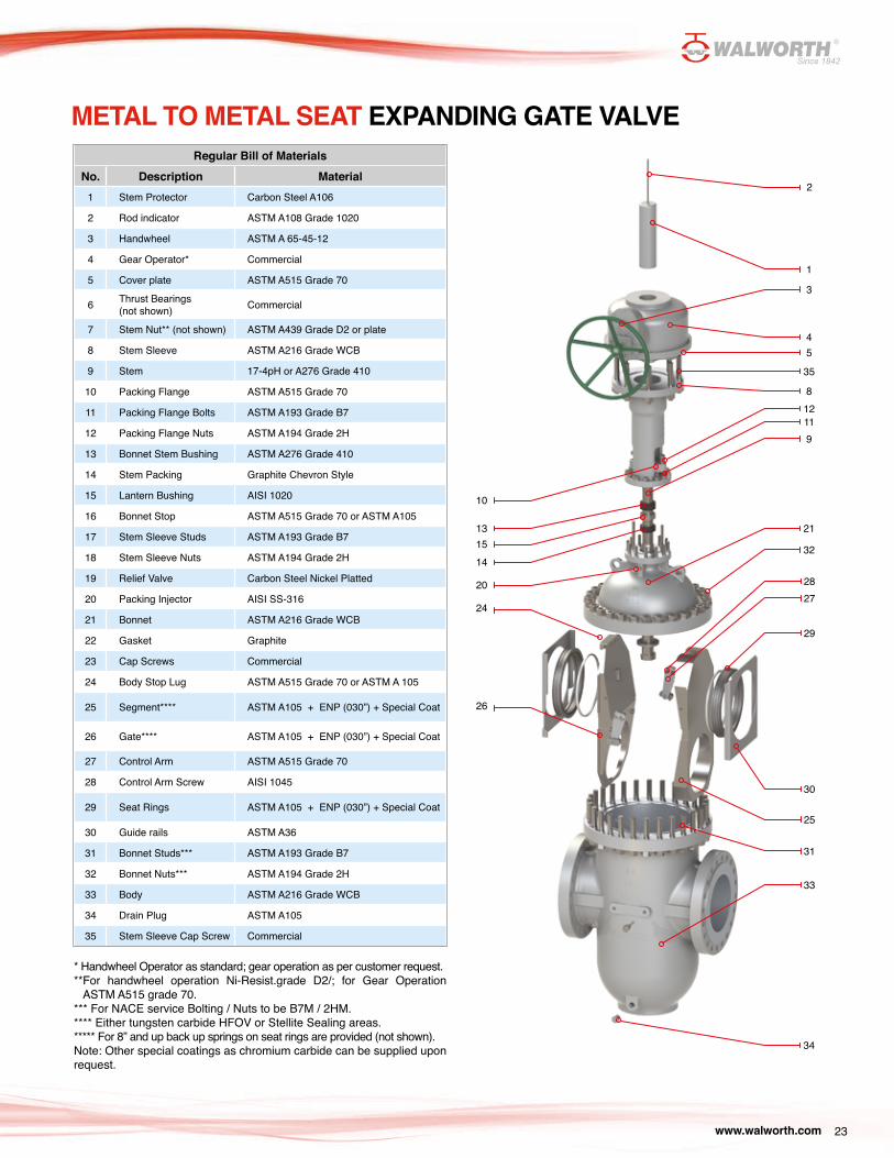
METAL TO METAL SEAT EXPANDING GATE VALVERegular Bill of Materials
No. Description Material1 Stem Protector Carbon Steel A106
2 Rod indicator ASTM A108 Grade 1020
3 Handwheel ASTM A 65-45-12
4 Gear Operator* Commercial
5 Cover plate ASTM A515 Grade 70
6 Thrust Bearings (not shown) Commercial
7 Stem Nut** (not shown) ASTM A439 Grade D2 or plate
8 Stem Sleeve ASTM A216 Grade WCB
9 Stem 17-4pH or A276 Grade 410
10 Packing Flange ASTM A515 Grade 70
11 Packing Flange Bolts ASTM A193 Grade B7
12 Packing Flange Nuts ASTM A194 Grade 2H
13 Bonnet Stem Bushing ASTM A276 Grade 410
14 Stem Packing Graphite Chevron Style
15 Lantern Bushing AISI 1020
16 Bonnet Stop ASTM A515 Grade 70 or ASTM A105
17 Stem Sleeve Studs ASTM A193 Grade B7
18 Stem Sleeve Nuts ASTM A194 Grade 2H
19 Relief Valve Carbon Steel Nickel Platted
20 Packing Injector AISI SS-316
21 Bonnet ASTM A216 Grade WCB
22 Gasket Graphite
23 Cap Screws Commercial
24 Body Stop Lug ASTM A515 Grade 70 or ASTM A 105
25 Segment**** ASTM A105 + ENP (030”) + Special Coat
26 Gate**** ASTM A105 + ENP (030”) + Special Coat
27 Control Arm ASTM A515 Grade 70
28 Control Arm Screw AISI 1045
29 Seat Rings ASTM A105 + ENP (030”) + Special Coat
30 Guide rails ASTM A36
31 Bonnet Studs*** ASTM A193 Grade B7
32 Bonnet Nuts*** ASTM A194 Grade 2H
33 Body ASTM A216 Grade WCB
34 Drain Plug ASTM A105
35 Stem Sleeve Cap Screw Commercial
* Handwheel Operator as standard; gear operation as per customer request.**For handwheel operation Ni-Resist.grade D2/; for Gear Operation ASTM A515 grade 70.*** For NACE service Bolting / Nuts to be B7M / 2HM.**** Either tungsten carbide HFOV or Stellite Sealing areas.***** For 8” and up back up springs on seat rings are provided (not shown).Note: Other special coatings as chromium carbide can be supplied upon request.
34
9
21
32
35
33
31
30
25
29
2728
13
10
14
20
24
26
15
45
1
2
8
3
1211
www.walworth.com24
EXPANDING GATE VALVE CLASS 150
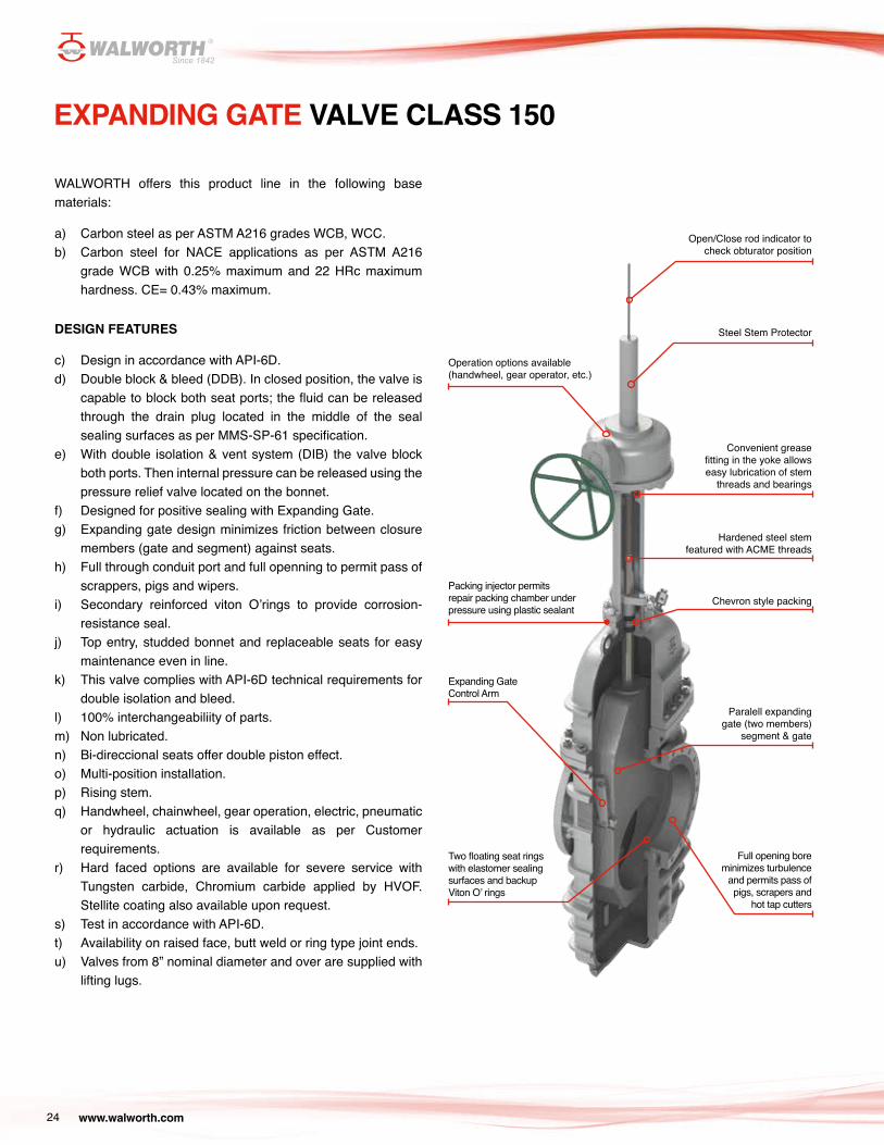
WALWORTH offers this product line in the following base materials:
a) Carbon steel as per ASTM A216 grades WCB, WCC.b) Carbon steel for NACE applications as per ASTM A216
grade WCB with 0.25% maximum and 22 HRc maximum hardness. CE= 0.43% maximum.
DESIGN FEATURES
c) Design in accordance with API-6D.d) Double block & bleed (DDB). In closed position, the valve is
capable to block both seat ports; the fluid can be released through the drain plug located in the middle of the seal sealing surfaces as per MMS-SP-61 specification.
e) With double isolation & vent system (DIB) the valve block both ports. Then internal pressure can be released using the pressure relief valve located on the bonnet.
f) Designed for positive sealing with Expanding Gate.g) Expanding gate design minimizes friction between closure
members (gate and segment) against seats.h) Full through conduit port and full openning to permit pass of
scrappers, pigs and wipers.i) Secondary reinforced viton O’rings to provide corrosion-
resistance seal.j) Top entry, studded bonnet and replaceable seats for easy
maintenance even in line.k) This valve complies with API-6D technical requirements for
double isolation and bleed.l) 100% interchangeabiliity of parts.m) Non lubricated.n) Bi-direccional seats offer double piston effect.o) Multi-position installation.p) Rising stem.q) Handwheel, chainwheel, gear operation, electric, pneumatic
or hydraulic actuation is available as per Customer requirements.
r) Hard faced options are available for severe service with Tungsten carbide, Chromium carbide applied by HVOF. Stellite coating also available upon request.
s) Test in accordance with API-6D.t) Availability on raised face, butt weld or ring type joint ends.u) Valves from 8” nominal diameter and over are supplied with
lifting lugs.
Open/Close rod indicator to check obturator position
Steel Stem Protector
Convenient grease fitting in the yoke allows easy lubrication of stem
threads and bearings
Operation options available (handwheel, gear operator, etc.)
Hardened steel stem featured with ACME threads
Packing injector permits repair packing chamber under pressure using plastic sealant
Chevron style packing
Full opening bore minimizes turbulence
and permits pass of pigs, scrapers and
hot tap cutters
Expanding Gate Control Arm
Two floating seat rings with elastomer sealing surfaces and backup Viton O’ rings
Paralell expanding gate (two members)
segment & gate
www.walworth.com 25
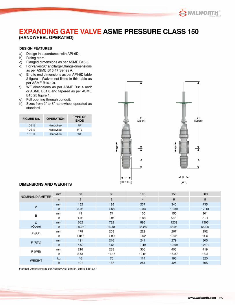
FIGURE No. OPERATION TYPE OF ENDS
1DE12 Handwheel RF1DE13 Handwheel RTJ1DE14 Handwheel WE
EXPANDING GATE VALVE ASME PRESSURE CLASS 150(HANDWHEEL OPERATED)
Flanged Dimensions as per ASME/ANSI B16.34, B16.5 & B16.47
B
C(Open)
F(RF/RTJ) (WE)
A
B
C(Open)
F
A
DESIGN FEATURES a) Design in accordance with API-6D.b) Rising stem.c) Flanged dimensions as per ASME B16.5.d) For valves 26” and larger, flange dimensions
as per ASME B16.47 Series A.e) End to end dimensions as per API-6D table
2 figure 1 (Valves not listed in this table as per ASME B16.10).
f) WE dimensions as per ASME B31.4 and/or ASME B31.8 and tapered as per ASME B16.25 figure 1.
g) Full opening through conduit.h) Sizes from 2” to 8” handwheel operated as
standard.
DIMENSIONS AND WEIGHTS
NOMINAL DIAMETERmm 50 80 100 150 200in 2 3 4 6 8
Amm 152 195 237 340 435in 5.98 7.68 9.33 13.39 17.13
Bmm 49 74 100 150 201in 1.93 2.91 3.94 5.91 7.91
C (Open)
mm 662 782 895 1239 1395in 26.08 30.81 35.26 48.81 54.96
F (RF)mm 178 203 229 267 292in 7.013 7.99 9.02 10.51 11.5
F (RTJ)mm 191 216 241 279 305in 7.52 8.51 9.49 10.99 12.01
F (WE)mm 216 283 305 403 419in 8.51 11.15 12.01 15.87 16.5
WEIGHTkg 46 76 114 193 320lb 101 167 251 425 705
www.walworth.com26
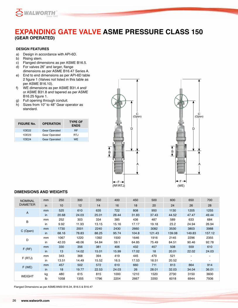
EXPANDING GATE VALVE ASME PRESSURE CLASS 150(GEAR OPERATED)
FIGURE No. OPERATION TYPE OF ENDS
1DE22 Gear Operated RF1DE23 Gear Operated RTJ1DE24 Gear Operated WE
DESIGN FEATURES a) Design in accordance with API-6D.b) Rising stem.c) Flanged dimensions as per ASME B16.5.d) For valves 26” and larger, flange
dimensions as per ASME B16.47 Series A.e) End to end dimensions as per API-6D table
2 figure 1 (Valves not listed in this table as per ASME B16.10).
f) WE dimensions as per ASME B31.4 and/or ASME B31.8 and tapered as per ASME B16.25 figure 1.
g) Full opening through conduit.h) Sizes from 10” to 48” Gear operator as
standard.
NOMINAL DIAMETER
mm 250 300 350 400 450 500 600 650 700in 10 12 14 16 18 20 24 26 28
Amm 525 610 635 722 808 950 1130 1205 1255in 20.68 24.03 25.01 28.44 31.83 37.43 44.52 47.47 49.44
Bmm 252 303 334 385 436 487 589 633 684in 9.92 11.93 13.15 15.16 17.17 19.18 23.2 24.94 26.94
C (Open)mm 1730 2001 2240 2430 2660 3082 3530 3803 3988in 68.16 78.83 88.25 95.74 104.8 121.43 139.08 149.83 157.12
Dmm 1067 1220 1392 1500 1646 1916 2145 2296 2355in 42.03 48.06 54.84 59.1 64.85 75.49 84.51 90.46 92.78
F (RF)mm 330 356 381 406 432 457 508 559 610in 13 14.02 15.01 15.99 17.02 18 20.01 22.02 24.03
F (RTJ)mm 343 368 394 419 445 470 521 - -in 13.51 14.49 15.52 16.5 17.53 18.51 20.52 - -
F (WE)mm 457 502 572 610 660 711 813 864 914in 18 19.77 22.53 24.03 26 28.01 32.03 34.04 36.01
WEIGHTkg 480 615 815 1000 1210 1520 2730 3150 3600lb 1058 1355 1796 2204 2667 3350 6018 6944 7936
Flanged Dimensions as per ASME/ANSI B16.34, B16.5 & B16.47
DIMENSIONS AND WEIGHTS
B
C(Open)
F
A
D
B
C(Open)
F
A
D
(RF/RTJ) (WE)
www.walworth.com 27
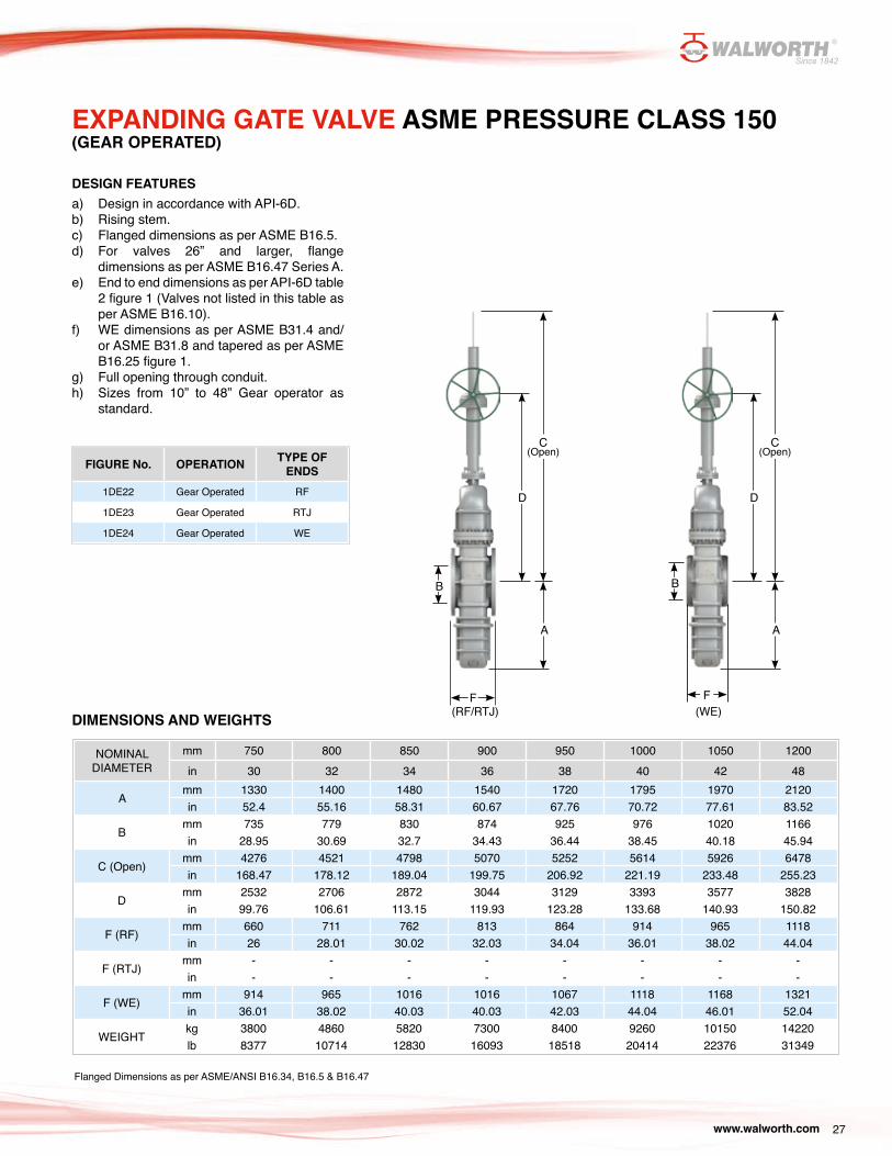
EXPANDING GATE VALVE ASME PRESSURE CLASS 150 (GEAR OPERATED)
FIGURE No. OPERATION TYPE OF ENDS
1DE22 Gear Operated RF
1DE23 Gear Operated RTJ
1DE24 Gear Operated WE
DESIGN FEATURES a) Design in accordance with API-6D.b) Rising stem.c) Flanged dimensions as per ASME B16.5.d) For valves 26” and larger, flange
dimensions as per ASME B16.47 Series A.e) End to end dimensions as per API-6D table
2 figure 1 (Valves not listed in this table as per ASME B16.10).
f) WE dimensions as per ASME B31.4 and/or ASME B31.8 and tapered as per ASME B16.25 figure 1.
g) Full opening through conduit.h) Sizes from 10” to 48” Gear operator as
standard.
NOMINAL DIAMETER
mm 750 800 850 900 950 1000 1050 1200in 30 32 34 36 38 40 42 48
Amm 1330 1400 1480 1540 1720 1795 1970 2120in 52.4 55.16 58.31 60.67 67.76 70.72 77.61 83.52
Bmm 735 779 830 874 925 976 1020 1166in 28.95 30.69 32.7 34.43 36.44 38.45 40.18 45.94
C (Open)mm 4276 4521 4798 5070 5252 5614 5926 6478in 168.47 178.12 189.04 199.75 206.92 221.19 233.48 255.23
Dmm 2532 2706 2872 3044 3129 3393 3577 3828in 99.76 106.61 113.15 119.93 123.28 133.68 140.93 150.82
F (RF)mm 660 711 762 813 864 914 965 1118in 26 28.01 30.02 32.03 34.04 36.01 38.02 44.04
F (RTJ)mm - - - - - - - -in - - - - - - - -
F (WE)mm 914 965 1016 1016 1067 1118 1168 1321in 36.01 38.02 40.03 40.03 42.03 44.04 46.01 52.04
WEIGHTkg 3800 4860 5820 7300 8400 9260 10150 14220lb 8377 10714 12830 16093 18518 20414 22376 31349
Flanged Dimensions as per ASME/ANSI B16.34, B16.5 & B16.47
DIMENSIONS AND WEIGHTS
B
C(Open)
F
A
D
B
C(Open)
A
D
F(RF/RTJ) (WE)

www.walworth.com28
EXPANDING GATE VALVE CLASS 300
WALWORTH offers this product line in the following base materials.
a) Carbon steel as per ASTM A216 grades WCB, WCC.b) Carbon steel for NACE applications as per ASTM A216
grade WCB with 0.25% maximum and 22 HRc maximum hardness. CE= 0.43% maximum.
DESIGN FEATURES
c) Design in accordance with API-6D.d) Double block & bleed (DDB). In closed position, the valve is
capable to block both seat ports; the fluid can be released through the drain plug located in the middle of the seal sealing surfaces as per MMS-SP-61 specification.
e) With double isolation & vent system (DIB) the valve block both ports. Then internal pressure can be released using the pressure relief valve located on the bonnet.
f) Designed for positive sealing with Expanding Gate.g) Expanding gate design minimizes friction between closure
members (gate and segment) against seats.h) Full through conduit port and full openning to permit pass of
scrappers, pigs and wipers.i) Secondary reinforced viton O’rings to provide corrosion-
resistance seal.j) Top entry, studded bonnet and replaceable seats for easy
maintenance even in line.k) This valve complies with API-6D technical requirements for
double isolation and bleed.l) 100% interchangeabiliity of parts.m) Non lubricated.n) Bi-direccional seats offer double piston effect.o) Multi-position installation.p) Rising stem.q) Handwheel, chainwheel, gear operation, electric, pneumatic or
hydraulic actuation is available as per Customer requirements.r) Hard faced options are available for severe service with
Tungsten carbide, Chromium carbide applied by HVOF. Stellite coating also available upon request.
s) Test in accordance with API-6D.t) Availability on raised face, butt weld or ring type joint ends.u) Valves from 8” nominal diameter and over are supplied with
lifting lugs.
Open/Close rod indicator to check obturator position
Steel Stem Protector
Convenient grease fitting in the yoke allows easy lubrication of stem
threads and bearings
Operation options available (handwheel, gear operator, etc.)
Hardened steel stem featured with ACME threads
Packing injector permits repair packing chamber under pressure using plastic sealant
Chevron style packing
Full opening bore minimizes turbulence
and permits pass of pigs, scrapers and
hot tap cutters
Expanding Gate Control Arm
Two floating seat rings with elastomer sealing surfaces and backup Viton O’ rings
Paralell expanding gate (two members)
segment & gate

www.walworth.com 29
FIGURE No. OPERATION TYPE OF ENDS
3DE12 Handwheel RF
3DE13 Handwheel RTJ
3DE14 Handwheel WE
EXPANDING GATE VALVE ASME PRESSURE CLASS 300(HANDWHEEL OPERATED)
DESIGN FEATURES a) Design in accordance with API-6D.b) Rising stem.c) Flanged dimensions as per ASME B16.5.d) For valves 26” and larger, flange dimensions
as per ASME B16.47 Series A.e) End to end dimensions as per API-6D table
2 figure 1 (Valves not listed in this table as per ASME B16.10).
f) WE dimensions as per ASME B31.4 and/or ASME B31.8 and tapered as per ASME B16.25 figure 1.
g) Full opening through conduit.h) Sizes from 2” to 8” handwheel operated as
standard.
Flanged Dimensions as per ASME/ANSI B16.34, B16.5 & B16.47
DIMENSIONS AND WEIGHTS
NOMINAL DIAMETERmm 50 80 100 150 200in 2 3 4 6 8
Amm 152 195 237 340 435in 5.98 7.68 9.33 13.39 17.13
Bmm 49 74 100 150 201in 1.93 2.91 3.94 5.91 7.91
C (Open)mm 662 782 895 1239 1395in 26.06 30.79 35.24 48.78 54.92
F (RF)mm 216 283 305 403 419in 8.51 11.15 12.01 15.87 16.5
F (RTJ)mm 232 298 321 419 435in 9.14 11.74 12.64 16.5 17.13
F (WE)mm 216 283 305 403 419in 8.51 11.15 12.01 15.87 16.5
WEIGHTkg 73 115 155 330 500lb 161 253 341 727 1102
A
B
F
C (Open)
F
A
B
C (Open)
(RF/RTJ) (WE)
www.walworth.com30
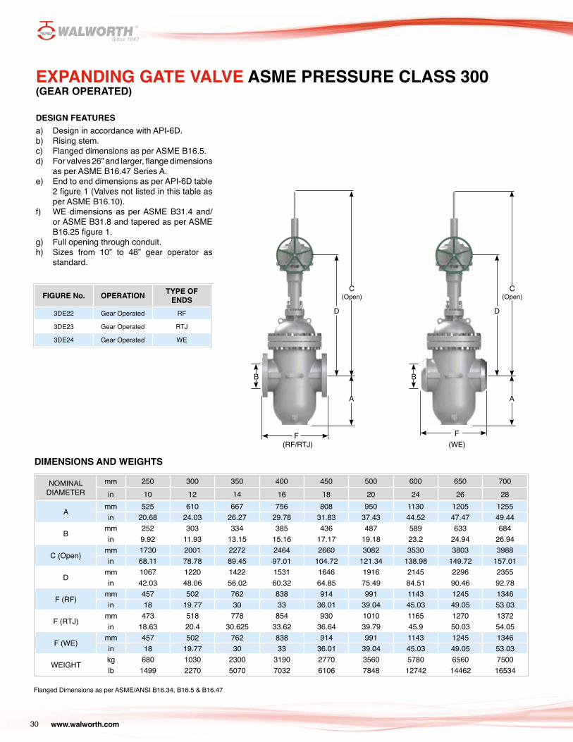
EXPANDING GATE VALVE ASME PRESSURE CLASS 300(GEAR OPERATED)
NOMINAL DIAMETER
mm 250 300 350 400 450 500 600 650 700in 10 12 14 16 18 20 24 26 28
Amm 525 610 667 756 808 950 1130 1205 1255in 20.68 24.03 26.27 29.78 31.83 37.43 44.52 47.47 49.44
Bmm 252 303 334 385 436 487 589 633 684in 9.92 11.93 13.15 15.16 17.17 19.18 23.2 24.94 26.94
C (Open)mm 1730 2001 2272 2464 2660 3082 3530 3803 3988in 68.11 78.78 89.45 97.01 104.72 121.34 138.98 149.72 157.01
Dmm 1067 1220 1422 1531 1646 1916 2145 2296 2355in 42.03 48.06 56.02 60.32 64.85 75.49 84.51 90.46 92.78
F (RF)mm 457 502 762 838 914 991 1143 1245 1346in 18 19.77 30 33 36.01 39.04 45.03 49.05 53.03
F (RTJ)mm 473 518 778 854 930 1010 1165 1270 1372in 18.63 20.4 30.625 33.62 36.64 39.79 45.9 50.03 54.05
F (WE)mm 457 502 762 838 914 991 1143 1245 1346in 18 19.77 30 33 36.01 39.04 45.03 49.05 53.03
WEIGHTkg 680 1030 2300 3190 2770 3560 5780 6560 7500lb 1499 2270 5070 7032 6106 7848 12742 14462 16534
Flanged Dimensions as per ASME/ANSI B16.34, B16.5 & B16.47
DIMENSIONS AND WEIGHTS
FIGURE No. OPERATION TYPE OF ENDS
3DE22 Gear Operated RF
3DE23 Gear Operated RTJ
3DE24 Gear Operated WE
DESIGN FEATURES a) Design in accordance with API-6D.b) Rising stem.c) Flanged dimensions as per ASME B16.5.d) For valves 26” and larger, flange dimensions
as per ASME B16.47 Series A.e) End to end dimensions as per API-6D table
2 figure 1 (Valves not listed in this table as per ASME B16.10).
f) WE dimensions as per ASME B31.4 and/or ASME B31.8 and tapered as per ASME B16.25 figure 1.
g) Full opening through conduit.h) Sizes from 10” to 48” gear operator as
standard.
F
A
B
C (Open)
D
A
B
F
C (Open)
D
(RF/RTJ) (WE)
www.walworth.com 31
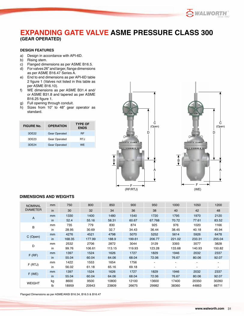
EXPANDING GATE VALVE ASME PRESSURE CLASS 300(GEAR OPERATED)
NOMINAL DIAMETER
mm 750 800 850 900 950 1000 1050 1200in 30 32 34 36 38 40 42 48
Amm 1330 1400 1480 1540 1720 1795 1970 2120in 52.4 55.16 58.31 60.67 67.768 70.72 77.61 83.52
Bmm 735 779 830 874 925 976 1020 1166in 28.95 30.69 32.7 34.43 36.44 38.45 40.18 45.94
C (Open)mm 4276 4521 4798 5070 5252 5614 5926 6478in 168.35 177.99 188.9 199.61 206.77 221.02 233.31 255.04
Dmm 2532 2706 2872 3044 3129 3393 3577 3828in 99.76 106.61 113.15 119.93 123.28 133.68 140.93 150.82
F (RF)mm 1397 1524 1626 1727 1829 1946 2032 2337in 55.04 60.04 64.06 68.04 72.06 76.67 80.06 92.07
F (RTJ)mm 1422 1553 1654 1756 - - - -in 56.02 61.18 65.16 69.18 - - - -
F (WE)mm 1397 1524 1626 1727 1829 1946 2032 2337in 55.04 60.04 64.06 68.04 72.06 76.67 80.06 92.07
WEIGHTkg 8600 9500 10800 12100 13600 17400 20350 30260lb 18959 20943 23809 26675 29982 38360 44863 66711
Flanged Dimensions as per ASME/ANSI B16.34, B16.5 & B16.47
DIMENSIONS AND WEIGHTS
FIGURE No. OPERATION TYPE OF ENDS
3DE22 Gear Operated RF
3DE23 Gear Operated RTJ
3DE24 Gear Operated WE
DESIGN FEATURES a) Design in accordance with API-6D.b) Rising stem.c) Flanged dimensions as per ASME B16.5.d) For valves 26” and larger, flange dimensions
as per ASME B16.47 Series A.e) End to end dimensions as per API-6D table
2 figure 1 (Valves not listed in this table as per ASME B16.10).
f) WE dimensions as per ASME B31.4 and/or ASME B31.8 and tapered as per ASME B16.25 figure 1.
g) Full opening through conduit.h) Sizes from 10” to 48” gear operator as
standard.
F
A
B
C (Open)
D
A
B
F
C (Open)
D
(RF/RTJ) (WE)

www.walworth.com32
EXPANDING GATE VALVE CLASS 600
WALWORTH offers this product line in the following base materials.
a) Carbon steel as per ASTM A216 grades WCB, WCC.b) Carbon steel for NACE applications as per ASTM A216
grade WCB with 0.25% maximum and 22 HRc maximum hardness. CE= 0.43% maximum.
DESIGN FEATURES
c) Design in accordance with API-6D.d) Double block & bleed (DDB). In closed position, the valve is
capable to block both seat ports; the fluid can be released through the drain plug located in the middle of the seal sealing surfaces as per MMS-SP-61 specification.
e) With double isolation & vent system (DIB) the valve block both ports. Then internal pressure can be released using the pressure relief valve located on the bonnet.
f) Designed for positive sealing with Expanding Gate.g) Expanding gate design minimizes friction between closure
members (gate and segment) against seats.h) Full through conduit port and full openning to permit pass of
scrappers, pigs and wipers.i) Secondary reinforced viton O’rings to provide corrosion-
resistance seal.j) Top entry, studded bonnet and replaceable seats for easy
maintenance even in line.k) This valve complies with API-6D technical requirements for
double isolation and bleed.l) 100% interchangeabiliity of parts.m) Non lubricated.n) Bi-direccional seats offer double piston effect.o) Multi-position installation.p) Rising stem.q) Handwheel, chainwheel, gear operation, electric, pneumatic
or hydraulic actuation is available as per Customer requirements.
r) Hard faced options are available for severe service with Tungsten carbide, Chromium carbide applied by HVOF. Stellite coating also available upon request.
s) Test in accordance with API-6D.t) Availability on raised face, butt weld or ring type joint ends.u) Valves from 8” nominal diameter and over are supplied with
lifting lugs.
Open/Close rod indicator to check obturator position
Steel Stem Protector
Convenient grease fitting in the yoke allows easy lubrication of stem
threads and bearings
Operation options available (handwheel, gear operator, etc.)
Hardened steel stem featured with ACME threads
Packing injector permits repair packing chamber under pressure using plastic sealant
Chevron style packing
Full opening bore minimizes turbulence
and permits pass of pigs, scrapers and
hot tap cutters
Expanding Gate Control Arm
Two floating seat rings with elastomer sealing surfaces and backup Viton O’ rings
Paralell expanding gate (two members)
segment & gate
www.walworth.com 33
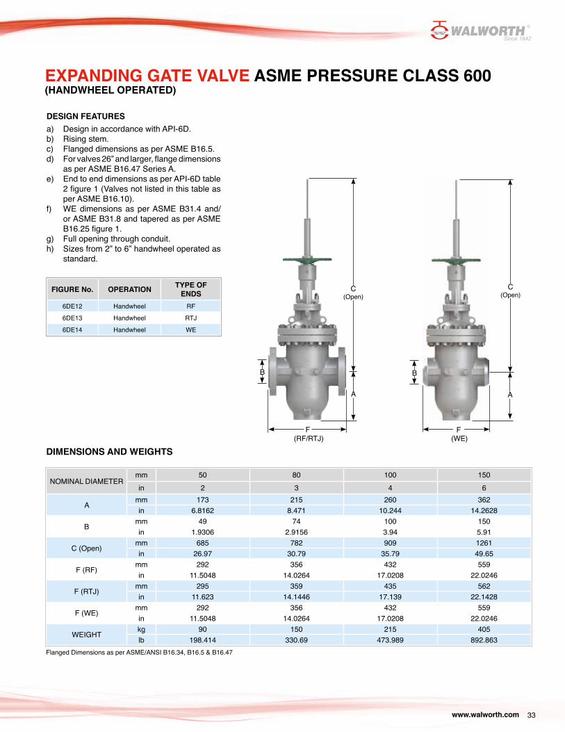
FIGURE No. OPERATION TYPE OF ENDS
6DE12 Handwheel RF
6DE13 Handwheel RTJ
6DE14 Handwheel WE
EXPANDING GATE VALVE ASME PRESSURE CLASS 600(HANDWHEEL OPERATED)
Flanged Dimensions as per ASME/ANSI B16.34, B16.5 & B16.47
DIMENSIONS AND WEIGHTS
NOMINAL DIAMETERmm 50 80 100 150in 2 3 4 6
Amm 173 215 260 362in 6.8162 8.471 10.244 14.2628
Bmm 49 74 100 150in 1.9306 2.9156 3.94 5.91
C (Open)mm 685 782 909 1261in 26.97 30.79 35.79 49.65
F (RF)mm 292 356 432 559in 11.5048 14.0264 17.0208 22.0246
F (RTJ)mm 295 359 435 562in 11.623 14.1446 17.139 22.1428
F (WE)mm 292 356 432 559in 11.5048 14.0264 17.0208 22.0246
WEIGHTkg 90 150 215 405lb 198.414 330.69 473.989 892.863
DESIGN FEATURES a) Design in accordance with API-6D.b) Rising stem.c) Flanged dimensions as per ASME B16.5.d) For valves 26” and larger, flange dimensions
as per ASME B16.47 Series A.e) End to end dimensions as per API-6D table
2 figure 1 (Valves not listed in this table as per ASME B16.10).
f) WE dimensions as per ASME B31.4 and/or ASME B31.8 and tapered as per ASME B16.25 figure 1.
g) Full opening through conduit.h) Sizes from 2” to 6” handwheel operated as
standard.
A
B
F
C (Open)
F
A
B
C (Open)
(RF/RTJ) (WE)
www.walworth.com34
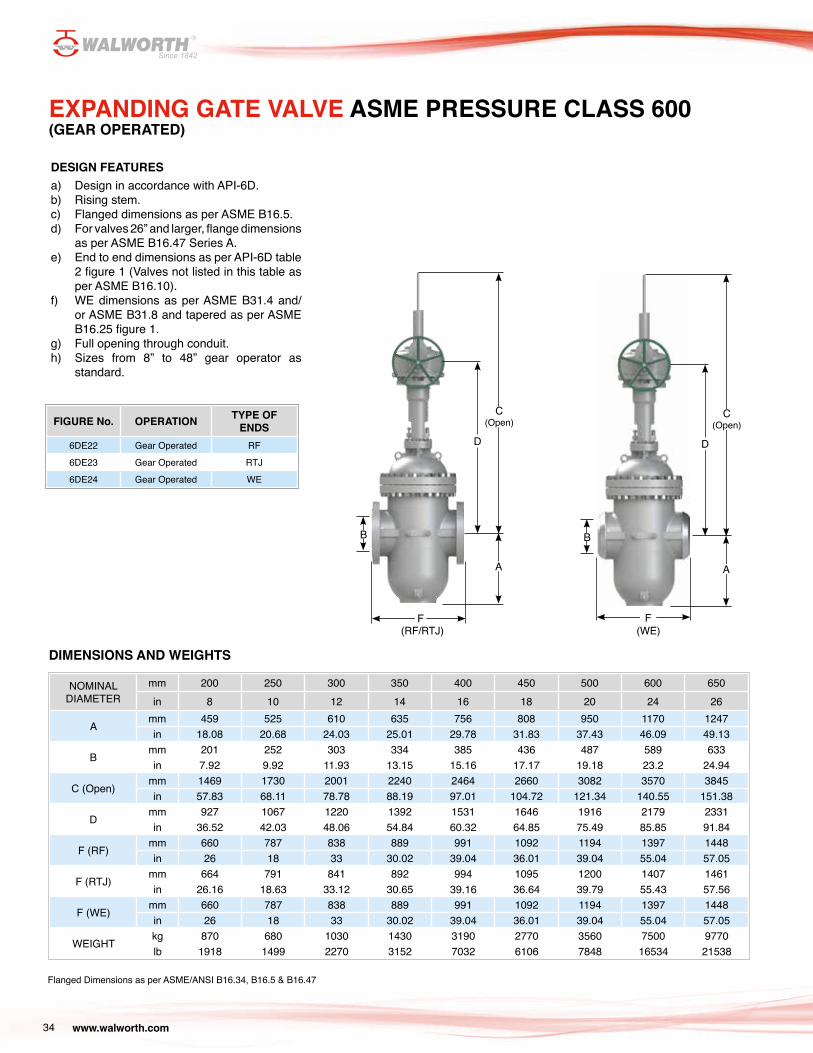
EXPANDING GATE VALVE ASME PRESSURE CLASS 600(GEAR OPERATED)
FIGURE No. OPERATION TYPE OF ENDS
6DE22 Gear Operated RF
6DE23 Gear Operated RTJ
6DE24 Gear Operated WE
NOMINAL DIAMETER
mm 200 250 300 350 400 450 500 600 650in 8 10 12 14 16 18 20 24 26
Amm 459 525 610 635 756 808 950 1170 1247in 18.08 20.68 24.03 25.01 29.78 31.83 37.43 46.09 49.13
Bmm 201 252 303 334 385 436 487 589 633in 7.92 9.92 11.93 13.15 15.16 17.17 19.18 23.2 24.94
C (Open)mm 1469 1730 2001 2240 2464 2660 3082 3570 3845in 57.83 68.11 78.78 88.19 97.01 104.72 121.34 140.55 151.38
Dmm 927 1067 1220 1392 1531 1646 1916 2179 2331in 36.52 42.03 48.06 54.84 60.32 64.85 75.49 85.85 91.84
F (RF)mm 660 787 838 889 991 1092 1194 1397 1448in 26 18 33 30.02 39.04 36.01 39.04 55.04 57.05
F (RTJ)mm 664 791 841 892 994 1095 1200 1407 1461in 26.16 18.63 33.12 30.65 39.16 36.64 39.79 55.43 57.56
F (WE)mm 660 787 838 889 991 1092 1194 1397 1448in 26 18 33 30.02 39.04 36.01 39.04 55.04 57.05
WEIGHTkg 870 680 1030 1430 3190 2770 3560 7500 9770lb 1918 1499 2270 3152 7032 6106 7848 16534 21538
Flanged Dimensions as per ASME/ANSI B16.34, B16.5 & B16.47
DIMENSIONS AND WEIGHTS
DESIGN FEATURES a) Design in accordance with API-6D.b) Rising stem.c) Flanged dimensions as per ASME B16.5.d) For valves 26” and larger, flange dimensions
as per ASME B16.47 Series A.e) End to end dimensions as per API-6D table
2 figure 1 (Valves not listed in this table as per ASME B16.10).
f) WE dimensions as per ASME B31.4 and/or ASME B31.8 and tapered as per ASME B16.25 figure 1.
g) Full opening through conduit.h) Sizes from 8” to 48” gear operator as
standard.
F
A
B
C (Open)
D
A
B
F
C (Open)
D
(RF/RTJ) (WE)

www.walworth.com 35
EXPANDING GATE VALVE ASME PRESSURE CLASS 600(GEAR OPERATED)
FIGURE No. OPERATION TYPE OF ENDS
6DE22 Gear Operated RF
6DE23 Gear Operated RTJ
6DE24 Gear Operated WE
NOMINAL DIAMETER
mm 700 750 800 850 900 950 1000 1050 1200in 28 30 32 34 36 38 40 42 48
Amm 1299 1376 1448 1530 1592 1774 1851 2028 2180in 51.18 54.21 57.05 60.28 62.72 69.89 72.92 79.9 85.89
Bmm 684 735 779 830 874 925 976 1020 1166in 26.94 28.95 30.69 32.7 34.43 36.44 38.45 40.18 45.94
C (Open)mm 4032 4322 4569 4848 5122 5306 5670 5984 6538in 158.74 170.16 179.88 190.87 201.65 208.9 223.23 235.59 257.4
Dmm 2391 2569 2744 2911 3084 3170 3435 3620 3872in 94.2 101.21 108.11 114.69 121.5 124.89 135.33 142.62 152.55
F (RF)mm 1549 1651 1778 1930 2083 2184 2286 2438 2794in 61.03 65.04 70.05 76.04 82.07 86.04 90.06 96.05 110.08
F (RTJ)mm 1562 1664 1794 1946 2099 - - - -in 61.54 65.56 70.68 76.67 82.7 - - - -
F (WE)mm 1549 1651 1778 1930 2083 2184 2286 2438 2794in 61.03 65.04 70.05 76.04 82.07 86.04 90.06 96.05 110.08
WEIGHTkg 11600 13600 15600 17800 20600 24150 25235 27950 38700lb 25573 29982 34391 39241 53241 53241 55633 61618 85318
Flanged Dimensions as per ASME/ANSI B16.34, B16.5 & B16.47
DIMENSIONS AND WEIGHTS
DESIGN FEATURES a) Design in accordance with API-6D.b) Rising stem.c) Flanged dimensions as per ASME B16.5.d) For valves 26” and larger, flange dimensions
as per ASME B16.47 Series A.e) End to end dimensions as per API-6D table
2 figure 1 (Valves not listed in this table as per ASME B16.10).
f) WE dimensions as per ASME B31.4 and/or ASME B31.8 and tapered as per ASME B16.25 figure 1.
g) Full opening through conduit.h) Sizes from 8” to 48” gear operator as
standard.
F
A
B
C (Open)
D
A
B
F
C (Open)
D
(RF/RTJ) (WE)
www.walworth.com36
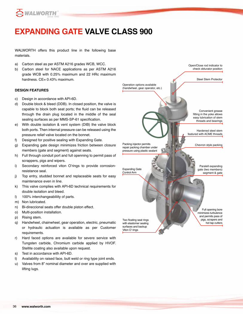
EXPANDING GATE VALVE CLASS 900
WALWORTH offers this product line in the following base materials.
a) Carbon steel as per ASTM A216 grades WCB, WCC.b) Carbon steel for NACE applications as per ASTM A216
grade WCB with 0.25% maximum and 22 HRc maximum hardness. CE= 0.43% maximum.
DESIGN FEATURES
c) Design in accordance with API-6D.d) Double block & bleed (DDB). In closed position, the valve is
capable to block both seat ports; the fluid can be released through the drain plug located in the middle of the seal sealing surfaces as per MMS-SP-61 specification.
e) With double isolation & vent system (DIB) the valve block both ports. Then internal pressure can be released using the pressure relief valve located on the bonnet.
f) Designed for positive sealing with Expanding Gate.g) Expanding gate design minimizes friction between closure
members (gate and segment) against seats.h) Full through conduit port and full openning to permit pass of
scrappers, pigs and wipers.i) Secondary reinforced viton O’rings to provide corrosion-
resistance seal.j) Top entry, studded bonnet and replaceable seats for easy
maintenance even in line.k) This valve complies with API-6D technical requirements for
double isolation and bleed.l) 100% interchangeabiliity of parts.m) Non lubricated.n) Bi-direccional seats offer double piston effect.o) Multi-position installation.p) Rising stem.q) Handwheel, chainwheel, gear operation, electric, pneumatic
or hydraulic actuation is available as per Customer requirements.
r) Hard faced options are available for severe service with Tungsten carbide, Chromium carbide applied by HVOF. Stellite coating also available upon request.
s) Test in accordance with API-6D.t) Availability on raised face, butt weld or ring type joint ends.u) Valves from 8” nominal diameter and over are supplied with
lifting lugs.
Open/Close rod indicator to check obturator position
Steel Stem Protector
Convenient grease fitting in the yoke allows easy lubrication of stem
threads and bearings
Operation options available (handwheel, gear operator, etc.)
Hardened steel stem featured with ACME threads
Packing injector permits repair packing chamber under pressure using plastic sealant
Chevron style packing
Full opening bore minimizes turbulence
and permits pass of pigs, scrapers and
hot tap cutters
Expanding Gate Control Arm
Two floating seat rings with elastomer sealing surfaces and backup Viton O’ rings
Paralell expanding gate (two members)
segment & gate
www.walworth.com 37
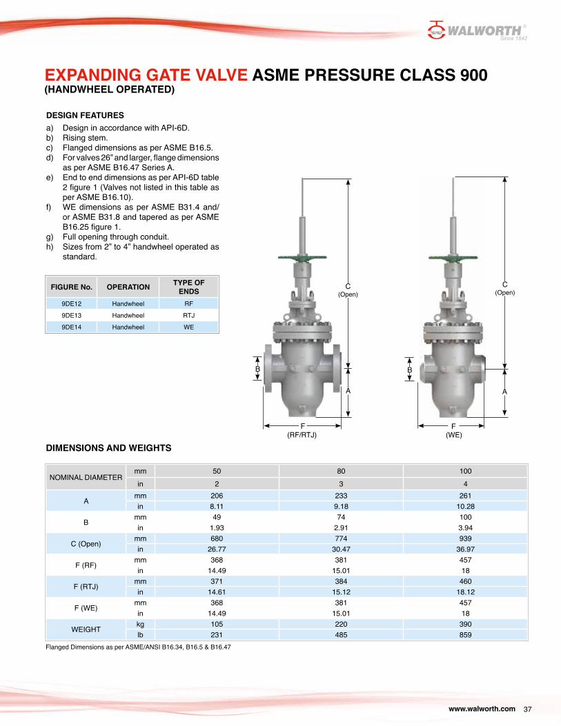
EXPANDING GATE VALVE ASME PRESSURE CLASS 900(HANDWHEEL OPERATED)
FIGURE No. OPERATION TYPE OF ENDS
9DE12 Handwheel RF
9DE13 Handwheel RTJ
9DE14 Handwheel WE
DESIGN FEATURES a) Design in accordance with API-6D.b) Rising stem.c) Flanged dimensions as per ASME B16.5.d) For valves 26” and larger, flange dimensions
as per ASME B16.47 Series A.e) End to end dimensions as per API-6D table
2 figure 1 (Valves not listed in this table as per ASME B16.10).
f) WE dimensions as per ASME B31.4 and/or ASME B31.8 and tapered as per ASME B16.25 figure 1.
g) Full opening through conduit.h) Sizes from 2” to 4” handwheel operated as
standard.
Flanged Dimensions as per ASME/ANSI B16.34, B16.5 & B16.47
DIMENSIONS AND WEIGHTS
NOMINAL DIAMETERmm 50 80 100in 2 3 4
Amm 206 233 261in 8.11 9.18 10.28
Bmm 49 74 100in 1.93 2.91 3.94
C (Open)mm 680 774 939in 26.77 30.47 36.97
F (RF)mm 368 381 457in 14.49 15.01 18
F (RTJ)mm 371 384 460in 14.61 15.12 18.12
F (WE)mm 368 381 457in 14.49 15.01 18
WEIGHTkg 105 220 390lb 231 485 859
A
B
F
C (Open)
F
A
B
C (Open)
(RF/RTJ) (WE)
www.walworth.com38
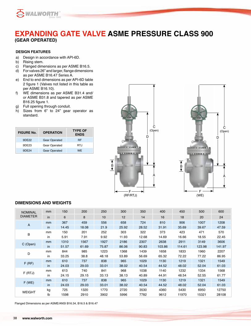
EXPANDING GATE VALVE ASME PRESSURE CLASS 900(GEAR OPERATED)
DESIGN FEATURES a) Design in accordance with API-6D.b) Rising stem.c) Flanged dimensions as per ASME B16.5.d) For valves 26” and larger, flange dimensions
as per ASME B16.47 Series A.e) End to end dimensions as per API-6D table
2 figure 1 (Valves not listed in this table as per ASME B16.10).
f) WE dimensions as per ASME B31.4 and/or ASME B31.8 and tapered as per ASME B16.25 figure 1.
g) Full opening through conduit.h) Sizes from 6” to 24” gear operator as
standard.
FIGURE No. OPERATION TYPE OF ENDS
9DE22 Gear Operated RF
9DE23 Gear Operated RTJ
9DE24 Gear Operated WE
NOMINAL DIAMETER
mm 150 200 250 300 350 400 450 500 600in 6 8 10 12 14 16 18 20 24
Amm 367 459 556 658 724 810 906 1007 1208in 14.45 18.08 21.9 25.92 28.52 31.91 35.69 39.67 47.59
Bmm 150 201 252 303 322 373 423 471 570in 5.91 7.91 9.92 11.93 12.68 14.69 16.66 18.55 22.45
C (Open)mm 1310 1567 1927 2186 2307 2638 2911 3149 3606in 51.57 61.69 75.87 86.06 90.83 103.86 114.61 123.98 141.97
Dmm 844 985 1223 1368 1439 1658 1833 1960 2207in 33.25 38.8 48.18 53.89 56.69 65.32 72.22 77.22 86.95
F (RF)mm 610 737 838 965 1029 1130 1219 1321 1549in 24.03 29.03 33.01 38.02 40.54 44.52 48.02 52.04 61.03
F (RTJ)mm 613 740 841 968 1038 1140 1232 1334 1568in 24.15 29.15 33.13 38.13 40.89 44.91 48.54 52.55 61.77
F (WE)mm 610 737 838 965 1029 1130 1219 1321 1549in 24.03 29.03 33.01 38.02 40.54 44.52 48.02 52.04 61.03
WEIGHTkg 725 1320 1770 2720 3530 4360 5430 6950 12750lb 1598 2910 3902 5996 7782 9612 11970 15321 28108
Flanged Dimensions as per ASME/ANSI B16.34, B16.5 & B16.47
DIMENSIONS AND WEIGHTS
F
A
B
C (Open)
D
A
B
F
C (Open)
D
(RF/RTJ) (WE)
www.walworth.com 39
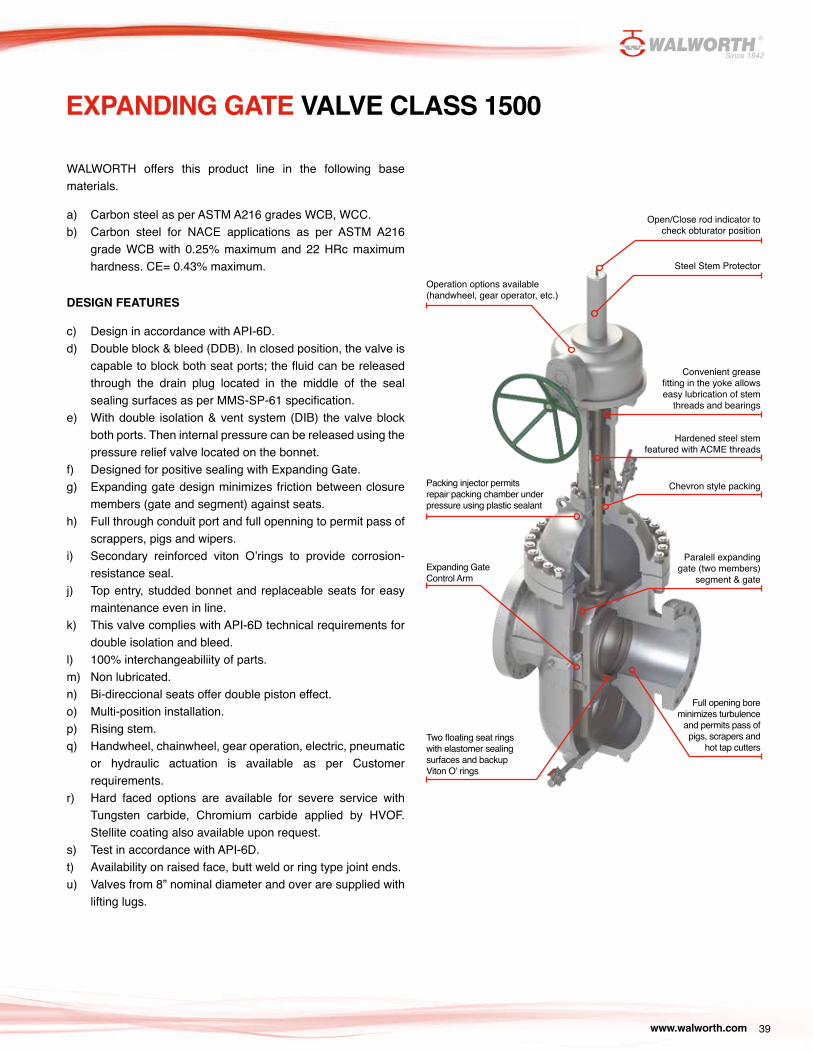
EXPANDING GATE VALVE CLASS 1500
WALWORTH offers this product line in the following base materials.
a) Carbon steel as per ASTM A216 grades WCB, WCC.b) Carbon steel for NACE applications as per ASTM A216
grade WCB with 0.25% maximum and 22 HRc maximum hardness. CE= 0.43% maximum.
DESIGN FEATURES
c) Design in accordance with API-6D.d) Double block & bleed (DDB). In closed position, the valve is
capable to block both seat ports; the fluid can be released through the drain plug located in the middle of the seal sealing surfaces as per MMS-SP-61 specification.
e) With double isolation & vent system (DIB) the valve block both ports. Then internal pressure can be released using the pressure relief valve located on the bonnet.
f) Designed for positive sealing with Expanding Gate.g) Expanding gate design minimizes friction between closure
members (gate and segment) against seats.h) Full through conduit port and full openning to permit pass of
scrappers, pigs and wipers.i) Secondary reinforced viton O’rings to provide corrosion-
resistance seal.j) Top entry, studded bonnet and replaceable seats for easy
maintenance even in line.k) This valve complies with API-6D technical requirements for
double isolation and bleed.l) 100% interchangeabiliity of parts.m) Non lubricated.n) Bi-direccional seats offer double piston effect.o) Multi-position installation.p) Rising stem.q) Handwheel, chainwheel, gear operation, electric, pneumatic
or hydraulic actuation is available as per Customer requirements.
r) Hard faced options are available for severe service with Tungsten carbide, Chromium carbide applied by HVOF. Stellite coating also available upon request.
s) Test in accordance with API-6D.t) Availability on raised face, butt weld or ring type joint ends.u) Valves from 8” nominal diameter and over are supplied with
lifting lugs.
Open/Close rod indicator to check obturator position
Steel Stem Protector
Convenient grease fitting in the yoke allows easy lubrication of stem
threads and bearings
Operation options available (handwheel, gear operator, etc.)
Hardened steel stem featured with ACME threads
Packing injector permits repair packing chamber under pressure using plastic sealant
Chevron style packing
Full opening bore minimizes turbulence
and permits pass of pigs, scrapers and
hot tap cutters
Expanding Gate Control Arm
Two floating seat rings with elastomer sealing surfaces and backup Viton O’ rings
Paralell expanding gate (two members)
segment & gate
www.walworth.com40
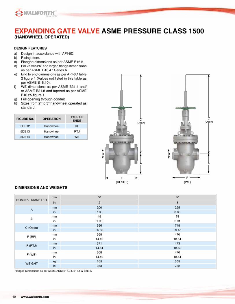
EXPANDING GATE VALVE ASME PRESSURE CLASS 1500(HANDWHEEL OPERATED)
FIGURE No. OPERATION TYPE OF ENDS
5DE12 Handwheel RF5DE13 Handwheel RTJ5DE14 Handwheel WE
DESIGN FEATURES a) Design in accordance with API-6D.b) Rising stem.c) Flanged dimensions as per ASME B16.5.d) For valves 26” and larger, flange dimensions
as per ASME B16.47 Series A.e) End to end dimensions as per API-6D table
2 figure 1 (Valves not listed in this table as per ASME B16.10).
f) WE dimensions as per ASME B31.4 and/or ASME B31.8 and tapered as per ASME B16.25 figure 1.
g) Full opening through conduit.h) Sizes from 2” to 3” handwheel operated as
standard.
Flanged Dimensions as per ASME/ANSI B16.34, B16.5 & B16.47
DIMENSIONS AND WEIGHTS
NOMINAL DIAMETERmm 50 80in 2 3
Amm 200 225in 7.88 8.86
Bmm 49 74in 1.93 2.91
C (Open)mm 656 748in 25.83 29.45
F (RF)mm 368 470in 14.49 18.51
F (RTJ)mm 371 473in 14.61 18.63
F (WE)mm 368 470in 14.49 18.51
WEIGHTkg 165 355lb 363 782
A
B
F
C (Open)
F
A
B
C (Open)
(RF/RTJ) (WE)
www.walworth.com 41
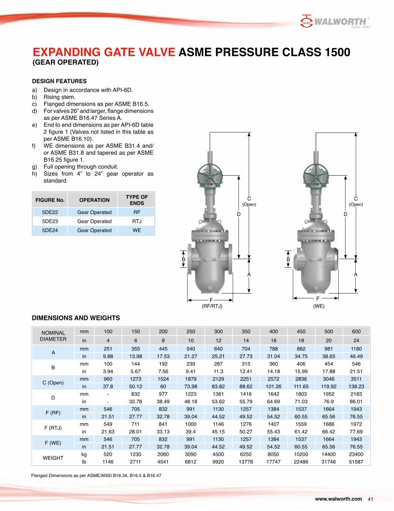
FIGURE No. OPERATION TYPE OF ENDS
5DE22 Gear Operated RF5DE23 Gear Operated RTJ5DE24 Gear Operated WE
EXPANDING GATE VALVE ASME PRESSURE CLASS 1500(GEAR OPERATED)
DESIGN FEATURES a) Design in accordance with API-6D.b) Rising stem.c) Flanged dimensions as per ASME B16.5.d) For valves 26” and larger, flange dimensions
as per ASME B16.47 Series A.e) End to end dimensions as per API-6D table
2 figure 1 (Valves not listed in this table as per ASME B16.10).
f) WE dimensions as per ASME B31.4 and/or ASME B31.8 and tapered as per ASME B16.25 figure 1.
g) Full opening through conduit.h) Sizes from 4” to 24” gear operator as
standard.
NOMINAL DIAMETER
mm 100 150 200 250 300 350 400 450 500 600in 4 6 8 10 12 14 16 18 20 24
Amm 251 355 445 540 640 704 788 882 981 1180in 9.88 13.98 17.53 21.27 25.21 27.73 31.04 34.75 38.65 46.49
Bmm 100 144 192 239 287 315 360 406 454 546in 3.94 5.67 7.56 9.41 11.3 12.41 14.18 15.99 17.88 21.51
C (Open)mm 960 1273 1524 1879 2129 2251 2572 2836 3046 3511in 37.8 50.12 60 73.98 83.82 88.62 101.26 111.65 119.92 138.23
Dmm - 832 977 1223 1361 1416 1642 1803 1952 2183in - 32.78 38.49 48.18 53.62 55.79 64.69 71.03 76.9 86.01
F (RF)mm 546 705 832 991 1130 1257 1384 1537 1664 1943in 21.51 27.77 32.78 39.04 44.52 49.52 54.52 60.55 65.56 76.55
F (RTJ)mm 549 711 841 1000 1146 1276 1407 1559 1686 1972in 21.63 28.01 33.13 39.4 45.15 50.27 55.43 61.42 66.42 77.69
F (WE)mm 546 705 832 991 1130 1257 1384 1537 1664 1943in 21.51 27.77 32.78 39.04 44.52 49.52 54.52 60.55 65.56 76.55
WEIGHTkg 520 1230 2060 3090 4500 6250 8050 10200 14400 23400lb 1146 2711 4541 6812 9920 13778 17747 22486 31746 51587
Flanged Dimensions as per ASME/ANSI B16.34, B16.5 & B16.47
DIMENSIONS AND WEIGHTS
F
A
B
C (Open)
D
A
B
F
C (Open)
D
(RF/RTJ) (WE)

www.walworth.com42
MOST COMMON TRIM ARRANGEMENTS
FEATURES METAL TO SOFT SEATDESCRIPTION ES1 ES2 ES3
TEMPERATURE -20ºF to 250ºF -20ºF to 250ºF -20ºF to 250ºF
(-29ºC to 121ºC) (-29ºC to 121ºC) (-29ºC to 121ºC)
SERVICESTANDARD TRIM FOR GENERAL,ENERGY, GAS AND OIL SERVICE
FOR CORROSION RESISTANCE SERVICE
TRIM FOR GENERAL,ENERGY, GAS AND OIL SERVICE
GATE & SEGMENT WCB, WCC or A105N + ENP (0.003") SS410 + ENP (0.003”) WCB, WCC or A105N + ENP (0.003")
SEAT RING A105N+ENP (0.003”) SS410 + ENP (0.003”) A105N+ENP (0.003”)
SEAT RING INSERT RPTFE OR NYLON SOFT SEAL (SEE TABLE 1)
RPTFE OR NYLON SOFT SEAL (SEE TABLE 1)
RPTFE OR NYLON SOFT SEAL (SEE TABLE 1)
STEM AISI 4140+ENP (0.003”) SS 410 17-4PH
FEATURES METAL TO SOFT SEATDESCRIPTION EM1 EM2 EM3 EM4 EM5 EM6
TEMPERATURE -20ºF to 550ºF -20ºF to 550ºF -20ºF to 550ºF -20ºF to 550ºF -20ºF to 550ºF -20ºF to 550ºF
(-29ºC to 288ºC) (-29ºC to 288ºC) (-29ºC to 288ºC) (-29ºC to 288ºC) (-29ºC to 288ºC) (-29ºC to 288ºC)
SERVICE
HIGH TEMPERATURE AND ABRASIVE RESISTANCE SERVICE
HIGH TEMPERATURE, ABRASIVE AND CORROSION RESISTANCE SERVICE
HIGH TEMPERATURE AND ABRASIVE RESISTANCE SERVICE
HIGH TEMPERATURE, ABRASIVE AND CORROSION RESISTANCE SERVICE
HIGH TEMPERATURE AND ABRASIVE RESISTANCE SERVICE
HIGH TEMPERATURE, ABRASIVE AND CORROSION RESISTANCE SERVICE
GATE & SEGMENT
WCB, WCC or A105N + TUNGSTEN CARBIDE*
SS 410 + TUNGSTEN CARBIDE*
WCB, WCC or A105N + STELLITE 6*
SS 410 + STELLITE 6*
WCB, WCC or A105N + CHROMIUM CARBIDE*
SS 410 + CHROMIUM CARBIDE*
SEAT RINGA105N + TUNGSTEN CARBIDE*
SS 410 + TUNGSTEN CARBIDE*
A105N + STELLITE 6*
SS 410 + STELLITE 6*
A105N + CHROMIUM CARBIDE*
SS 410 + CHROMIUM CARBIDE*
SEAT RING INSERT - (METAL TO METAL SEAL)
- (METAL TO METAL SEAL)
- (METAL TO METAL SEAL)
- (METAL TO METAL SEAL)
- (METAL TO METAL SEAL)
- (METAL TO METAL SEAL)
STEM SS 410 SS 410 SS 410 SS 410 SS 410 SS 410
METAL TO SOFT SEAT
METAL TO METAL SEAT
*Hard Overlay is normally of 0.006” thickness Notes: a. Special arrangements can be supplied as per Customers request.b. All valves are suitable for Sour Service as they comply with NACE MR0175
www.walworth.com 43
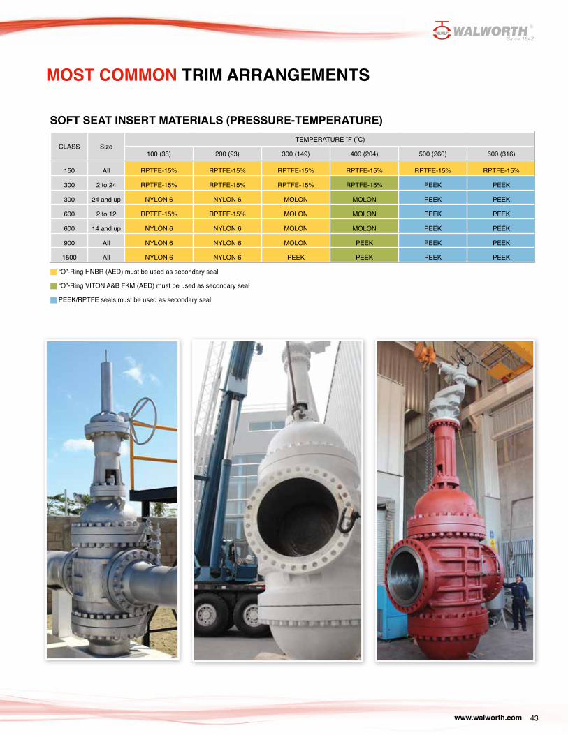
MOST COMMON TRIM ARRANGEMENTS
SOFT SEAT INSERT MATERIALS (PRESSURE-TEMPERATURE)
“O”-Ring HNBR (AED) must be used as secondary seal
“O”-Ring VITON A&B FKM (AED) must be used as secondary seal
PEEK/RPTFE seals must be used as secondary seal
CLASS SizeTEMPERATURE ˚F (˚C)
100 (38) 200 (93) 300 (149) 400 (204) 500 (260) 600 (316)
150 All RPTFE-15% RPTFE-15% RPTFE-15% RPTFE-15% RPTFE-15% RPTFE-15%
300 2 to 24 RPTFE-15% RPTFE-15% RPTFE-15% RPTFE-15% PEEK PEEK
300 24 and up NYLON 6 NYLON 6 MOLON MOLON PEEK PEEK
600 2 to 12 RPTFE-15% RPTFE-15% MOLON MOLON PEEK PEEK
600 14 and up NYLON 6 NYLON 6 MOLON MOLON PEEK PEEK
900 All NYLON 6 NYLON 6 MOLON PEEK PEEK PEEK
1500 All NYLON 6 NYLON 6 PEEK PEEK PEEK PEEK

www.walworth.com44
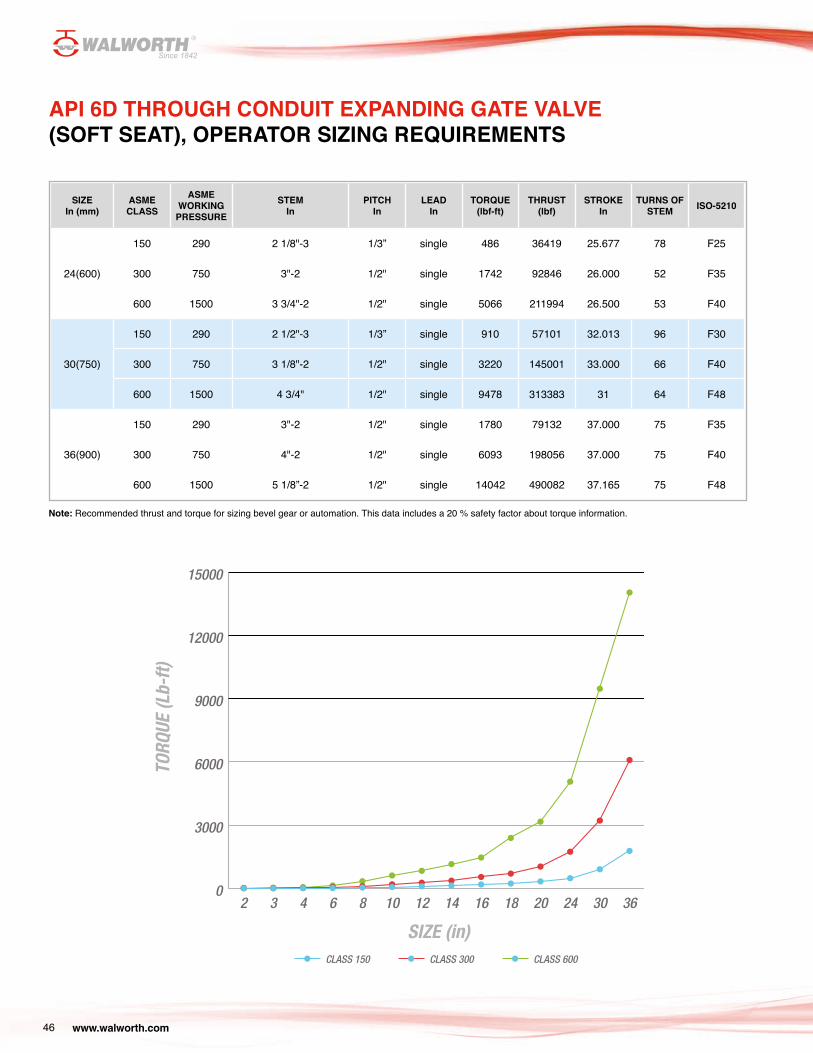
Note: Recommended thrust and torque for sizing bevel gear or automation. This data includes a 20 % safety factor about torque information.
* WALWORTH Expanding Gate Valves with gear operator are supplied with ISO flanges in accordance with ISO-5210.Bare stem valves will be supplied with ISO flange upon request.
Continues...
API 6D THROUGH CONDUIT EXPANDING GATE VALVE (SOFT SEAT), OPERATOR SIZING REQUIREMENTS
STEM DIAM. PITCH LEAD
STROKE
ISO-5210*
SIZEIn (mm)
ASME CLASS
ASME WORKING
PRESSURE
STEM In
PITCHIn
LEADIn
TORQUE(lbf-ft)
THRUST(lbf)
STROKEIn
TURNS OF STEM ISO-5210
2 (50)
150 290 7/8"-6 1/6" single 4 675 3.164 20 F10
300 750 7/8"-6 1/6" single 19 1574 3.164 20 F10
600 1500 7/8"-6 1/6" single 19 3597 3.164 20 F10
3 (80)
150 290 7/8"-6 1/6" single 6 1124 4.163 27 F10
300 750 1"-5 1/5" single 16 2698 4.2 21 F10
600 1500 1"-5 1/5" single 35 5845 4.2 21 F10
4(100)
150 290 1”-5 1/5" single 11 1574 5.2 26 F10
300 750 1 1/8"-5 1/5" single 27 3822 5.2 26 F12
600 1500 1 1/8"-5 1/5" single 59 8543 5.2 26 F12
www.walworth.com 45
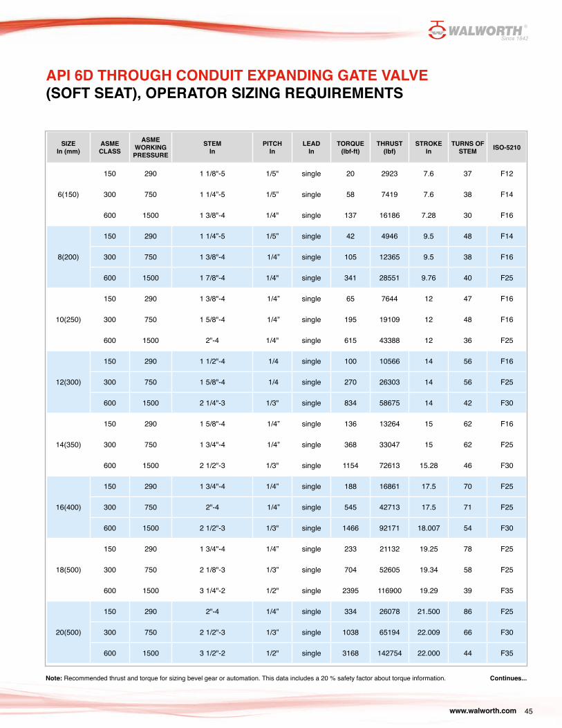
API 6D THROUGH CONDUIT EXPANDING GATE VALVE (SOFT SEAT), OPERATOR SIZING REQUIREMENTS
SIZEIn (mm)
ASME CLASS
ASME WORKING
PRESSURESTEM
InPITCH
InLEAD
InTORQUE
(lbf-ft)THRUST
(lbf)STROKE
InTURNS OF
STEM ISO-5210
6(150)
150 290 1 1/8"-5 1/5" single 20 2923 7.6 37 F12
300 750 1 1/4”-5 1/5” single 58 7419 7.6 38 F14
600 1500 1 3/8"-4 1/4" single 137 16186 7.28 30 F16
8(200)
150 290 1 1/4”-5 1/5” single 42 4946 9.5 48 F14
300 750 1 3/8"-4 1/4” single 105 12365 9.5 38 F16
600 1500 1 7/8"-4 1/4" single 341 28551 9.76 40 F25
10(250)
150 290 1 3/8"-4 1/4” single 65 7644 12 47 F16
300 750 1 5/8"-4 1/4” single 195 19109 12 48 F16
600 1500 2"-4 1/4" single 615 43388 12 36 F25
12(300)
150 290 1 1/2"-4 1/4 single 100 10566 14 56 F16
300 750 1 5/8"-4 1/4 single 270 26303 14 56 F25
600 1500 2 1/4"-3 1/3" single 834 58675 14 42 F30
14(350)
150 290 1 5/8"-4 1/4” single 136 13264 15 62 F16
300 750 1 3/4"-4 1/4” single 368 33047 15 62 F25
600 1500 2 1/2"-3 1/3" single 1154 72613 15.28 46 F30
16(400)
150 290 1 3/4"-4 1/4” single 188 16861 17.5 70 F25
300 750 2"-4 1/4” single 545 42713 17.5 71 F25
600 1500 2 1/2"-3 1/3" single 1466 92171 18.007 54 F30
18(500)
150 290 1 3/4"-4 1/4” single 233 21132 19.25 78 F25
300 750 2 1/8"-3 1/3” single 704 52605 19.34 58 F25
600 1500 3 1/4"-2 1/2" single 2395 116900 19.29 39 F35
20(500)
150 290 2"-4 1/4” single 334 26078 21.500 86 F25
300 750 2 1/2"-3 1/3” single 1038 65194 22.009 66 F30
600 1500 3 1/2"-2 1/2" single 3168 142754 22.000 44 F35
Note: Recommended thrust and torque for sizing bevel gear or automation. This data includes a 20 % safety factor about torque information. Continues...
www.walworth.com46
SIZEIn (mm)
ASME CLASS
ASME WORKING
PRESSURESTEM
InPITCH
InLEAD
InTORQUE
(lbf-ft)THRUST
(lbf)STROKE
InTURNS OF
STEM ISO-5210
24(600)
150 290 2 1/8"-3 1/3” single 486 36419 25.677 78 F25
300 750 3"-2 1/2" single 1742 92846 26.000 52 F35
600 1500 3 3/4"-2 1/2" single 5066 211994 26.500 53 F40
30(750)
150 290 2 1/2"-3 1/3” single 910 57101 32.013 96 F30
300 750 3 1/8"-2 1/2" single 3220 145001 33.000 66 F40
600 1500 4 3/4" 1/2" single 9478 313383 31 64 F48
36(900)
150 290 3"-2 1/2" single 1780 79132 37.000 75 F35
300 750 4"-2 1/2" single 6093 198056 37.000 75 F40
600 1500 5 1/8”-2 1/2" single 14042 490082 37.165 75 F48
0
3000
6000
9000
12000
15000
CLASS 600CLASS 300CLASS 150
36302420181614121086432
TORQ
UE (L
b-ft)
SIZE (in)
Note: Recommended thrust and torque for sizing bevel gear or automation. This data includes a 20 % safety factor about torque information.
API 6D THROUGH CONDUIT EXPANDING GATE VALVE (SOFT SEAT), OPERATOR SIZING REQUIREMENTS
www.walworth.com 47
WALWORTH Expanding Gate Valves can be supplied with flanged ends in raised face, flat faces or ring joint type as well as in welding ends (buttweld). They can also be supplied with combined ends, such as flanged by weld, in accordance to customer requirements.
The buttweld ends in standard valves are machined in accordance with ASME B 31.4 and/or ASME B 31.8 and tapered as per ASME B16.5 figure 1; are supplied to meet the following pipe schedules:
TYPES OF END CONNECTIONS
Valve
Valve Valve
ValvePipe
Pipe Pipe
Pipe
Flanged EndsFlat Face
Flanged EndsRing Type Joint
Flanged EndsRaised Face
Weld Ends Buttweld
Valve Pressure Class Weld End Pipe Schedule
150/300 Schedule 40 – 2" to 10" Standard Wall – 12" to 24"
600 Schedule 80
900 Schedule 160 – 2" to 3" Schedule 120 – 4" and Larger
1500 Schedule 160
TECHNICAL INFORMATION
The customer must clearly specify the pipe wall thickness and type of pipe to be welded to the valves for schedules different than the above.
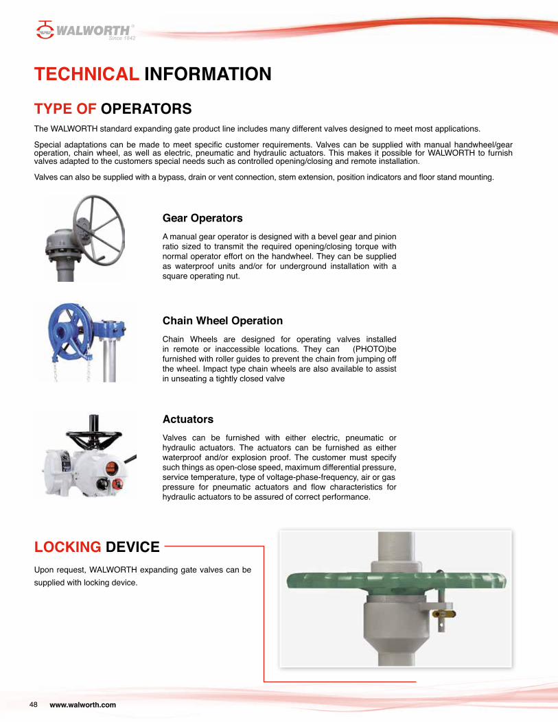
www.walworth.com48
The WALWORTH standard expanding gate product line includes many different valves designed to meet most applications.
Special adaptations can be made to meet specific customer requirements. Valves can be supplied with manual handwheel/gear operation, chain wheel, as well as electric, pneumatic and hydraulic actuators. This makes it possible for WALWORTH to furnish valves adapted to the customers special needs such as controlled opening/closing and remote installation.
Valves can also be supplied with a bypass, drain or vent connection, stem extension, position indicators and floor stand mounting.
TYPE OF OPERATORS
Gear Operators A manual gear operator is designed with a bevel gear and pinion ratio sized to transmit the required opening/closing torque with normal operator effort on the handwheel. They can be supplied as waterproof units and/or for underground installation with a square operating nut.
TECHNICAL INFORMATION
LOCKING DEVICEUpon request, WALWORTH expanding gate valves can be supplied with locking device.
Chain Wheel Operation Chain Wheels are designed for operating valves installed in remote or inaccessible locations. They can (PHOTO)be furnished with roller guides to prevent the chain from jumping off the wheel. Impact type chain wheels are also available to assist in unseating a tightly closed valve
Actuators Valves can be furnished with either electric, pneumatic or hydraulic actuators. The actuators can be furnished as either waterproof and/or explosion proof. The customer must specify such things as open-close speed, maximum differential pressure, service temperature, type of voltage-phase-frequency, air or gas pressure for pneumatic actuators and flow characteristics for hydraulic actuators to be assured of correct performance.
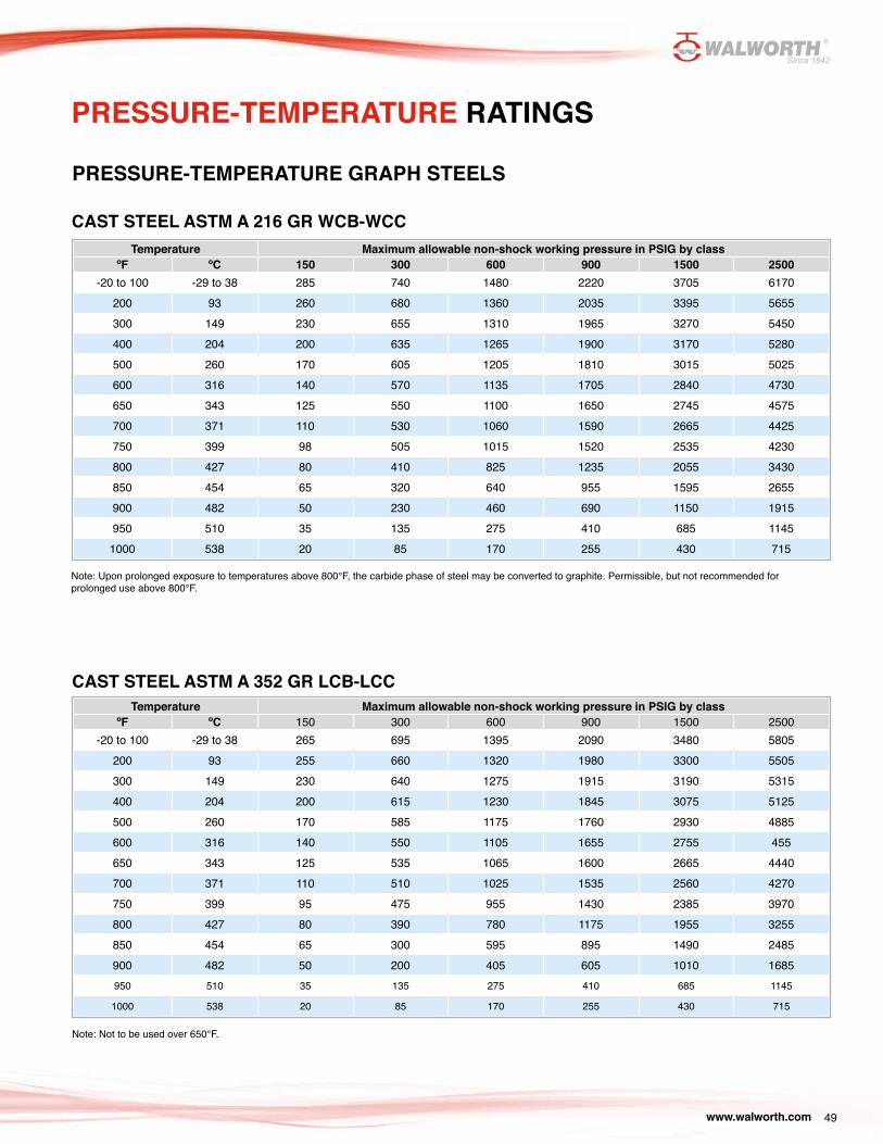
www.walworth.com 49
PRESSURE-TEMPERATURE RATINGS
Temperature Maximum allowable non-shock working pressure in PSIG by classºF ºC 150 300 600 900 1500 2500
-20 to 100 -29 to 38 285 740 1480 2220 3705 6170200 93 260 680 1360 2035 3395 5655300 149 230 655 1310 1965 3270 5450400 204 200 635 1265 1900 3170 5280500 260 170 605 1205 1810 3015 5025600 316 140 570 1135 1705 2840 4730650 343 125 550 1100 1650 2745 4575700 371 110 530 1060 1590 2665 4425750 399 98 505 1015 1520 2535 4230800 427 80 410 825 1235 2055 3430850 454 65 320 640 955 1595 2655900 482 50 230 460 690 1150 1915950 510 35 135 275 410 685 1145
1000 538 20 85 170 255 430 715
CAST STEEL ASTM A 216 GR WCB-WCC
Note: Upon prolonged exposure to temperatures above 800°F, the carbide phase of steel may be converted to graphite. Permissible, but not recommended for prolonged use above 800°F.
PRESSURE-TEMPERATURE GRAPH STEELS
Temperature Maximum allowable non-shock working pressure in PSIG by classºF ºC 150 300 600 900 1500 2500
-20 to 100 -29 to 38 265 695 1395 2090 3480 5805200 93 255 660 1320 1980 3300 5505300 149 230 640 1275 1915 3190 5315400 204 200 615 1230 1845 3075 5125500 260 170 585 1175 1760 2930 4885600 316 140 550 1105 1655 2755 455650 343 125 535 1065 1600 2665 4440700 371 110 510 1025 1535 2560 4270750 399 95 475 955 1430 2385 3970800 427 80 390 780 1175 1955 3255850 454 65 300 595 895 1490 2485900 482 50 200 405 605 1010 1685950 510 35 135 275 410 685 1145
1000 538 20 85 170 255 430 715
CAST STEEL ASTM A 352 GR LCB-LCC
Note: Not to be used over 650°F.
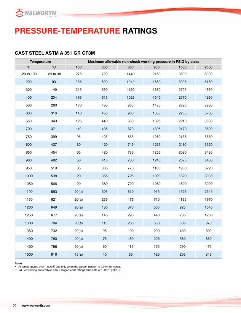
www.walworth.com50
PRESSURE-TEMPERATURE RATINGS
Temperature Maximum allowable non-shock working pressure in PSIG by classºF ºC 150 300 600 900 1500 2500
-20 to 100 -29 to 38 275 720 1440 2160 3600 6000
200 93 235 620 1240 1860 3095 5160
300 149 215 560 1120 1680 2795 4660
400 204 195 515 1025 1540 2570 4280
500 260 170 480 955 1435 2390 3980
600 316 140 450 900 1355 2255 3760
650 343 125 440 885 1325 2210 3680
700 371 110 435 870 1305 2170 3620
750 399 95 425 855 1280 2135 3560
800 427 80 420 745 1265 2110 3520
850 454 65 420 735 1255 2090 3480
900 482 50 415 730 1245 2075 3460
950 510 35 385 775 1160 1930 3220
1000 538 20 365 725 1090 1820 3030
1050 566 20 360 720 1080 1800 3000
1100 593 20(a) 305 610 915 1525 2545
1150 621 20(a) 235 475 710 1185 1970
1200 649 20(a) 185 370 555 925 1545
1250 677 20(a) 145 295 440 735 1230
1300 704 20(a) 115 235 350 585 970
1350 732 20(a) 95 190 290 480 800
1400 760 20(a) 75 150 225 380 630
1450 788 20(a) 60 115 175 290 475
1500 816 15(a) 40 85 125 205 345
CAST STEEL ASTM A 351 GR CF8M
Notes:• At temperatures over 1,000°F, use only when the carbon content is 0.04% or higher. • (a) For welding ends valves only. Flanged ends ratings terminate at 1000°F (538°C).
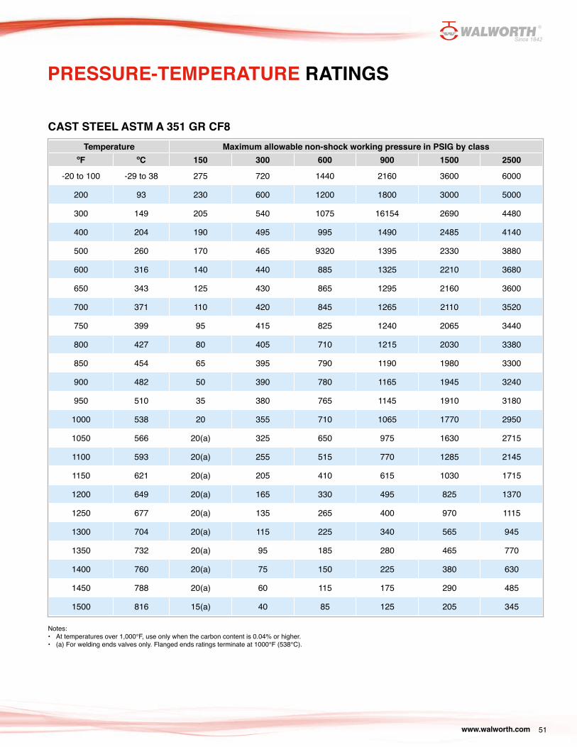
www.walworth.com 51
PRESSURE-TEMPERATURE RATINGS
Temperature Maximum allowable non-shock working pressure in PSIG by classºF ºC 150 300 600 900 1500 2500
-20 to 100 -29 to 38 275 720 1440 2160 3600 6000
200 93 230 600 1200 1800 3000 5000
300 149 205 540 1075 16154 2690 4480
400 204 190 495 995 1490 2485 4140
500 260 170 465 9320 1395 2330 3880
600 316 140 440 885 1325 2210 3680
650 343 125 430 865 1295 2160 3600
700 371 110 420 845 1265 2110 3520
750 399 95 415 825 1240 2065 3440
800 427 80 405 710 1215 2030 3380
850 454 65 395 790 1190 1980 3300
900 482 50 390 780 1165 1945 3240
950 510 35 380 765 1145 1910 3180
1000 538 20 355 710 1065 1770 2950
1050 566 20(a) 325 650 975 1630 2715
1100 593 20(a) 255 515 770 1285 2145
1150 621 20(a) 205 410 615 1030 1715
1200 649 20(a) 165 330 495 825 1370
1250 677 20(a) 135 265 400 970 1115
1300 704 20(a) 115 225 340 565 945
1350 732 20(a) 95 185 280 465 770
1400 760 20(a) 75 150 225 380 630
1450 788 20(a) 60 115 175 290 485
1500 816 15(a) 40 85 125 205 345
CAST STEEL ASTM A 351 GR CF8
Notes:• At temperatures over 1,000°F, use only when the carbon content is 0.04% or higher. • (a) For welding ends valves only. Flanged ends ratings terminate at 1000°F (538°C).
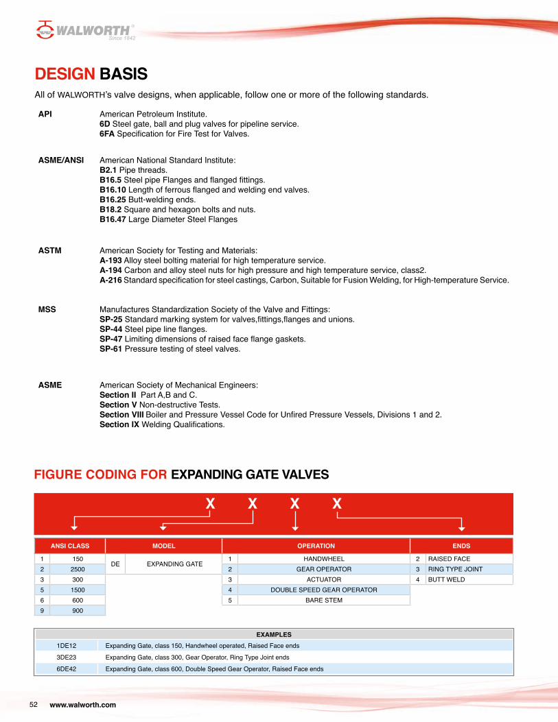
www.walworth.com52
DESIGN BASISAll of WALWORTH’s valve designs, when applicable, follow one or more of the following standards.
API American Petroleum Institute.6D Steel gate, ball and plug valves for pipeline service.6FA Specification for Fire Test for Valves.
ASME/ANSI American National Standard Institute:B2.1 Pipe threads.B16.5 Steel pipe Flanges and flanged fittings.B16.10 Length of ferrous flanged and welding end valves.B16.25 Butt-welding ends.B18.2 Square and hexagon bolts and nuts.B16.47 Large Diameter Steel Flanges
ASTM American Society for Testing and Materials:A-193 Alloy steel bolting material for high temperature service.A-194 Carbon and alloy steel nuts for high pressure and high temperature service, class2.A-216 Standard specification for steel castings, Carbon, Suitable for Fusion Welding, for High-temperature Service.
MSS Manufactures Standardization Society of the Valve and Fittings:SP-25 Standard marking system for valves,fittings,flanges and unions.SP-44 Steel pipe line flanges.SP-47 Limiting dimensions of raised face flange gaskets.SP-61 Pressure testing of steel valves.
ASME American Society of Mechanical Engineers:Section II Part A,B and C.Section V Non-destructive Tests.Section VIII Boiler and Pressure Vessel Code for Unfired Pressure Vessels, Divisions 1 and 2.Section IX Welding Qualifications.
EXAMPLES1DE12 Expanding Gate, class 150, Handwheel operated, Raised Face ends
3DE23 Expanding Gate, class 300, Gear Operator, Ring Type Joint ends
6DE42 Expanding Gate, class 600, Double Speed Gear Operator, Raised Face ends
FIGURE CODING FOR EXPANDING GATE VALVES
X X X X
ANSI CLASS MODEL OPERATION ENDS
1 150DE EXPANDING GATE
1 HANDWHEEL 2 RAISED FACE2 2500 2 GEAR OPERATOR 3 RING TYPE JOINT3 300 3 ACTUATOR 4 BUTT WELD5 1500 4 DOUBLE SPEED GEAR OPERATOR6 600 5 BARE STEM 9 900
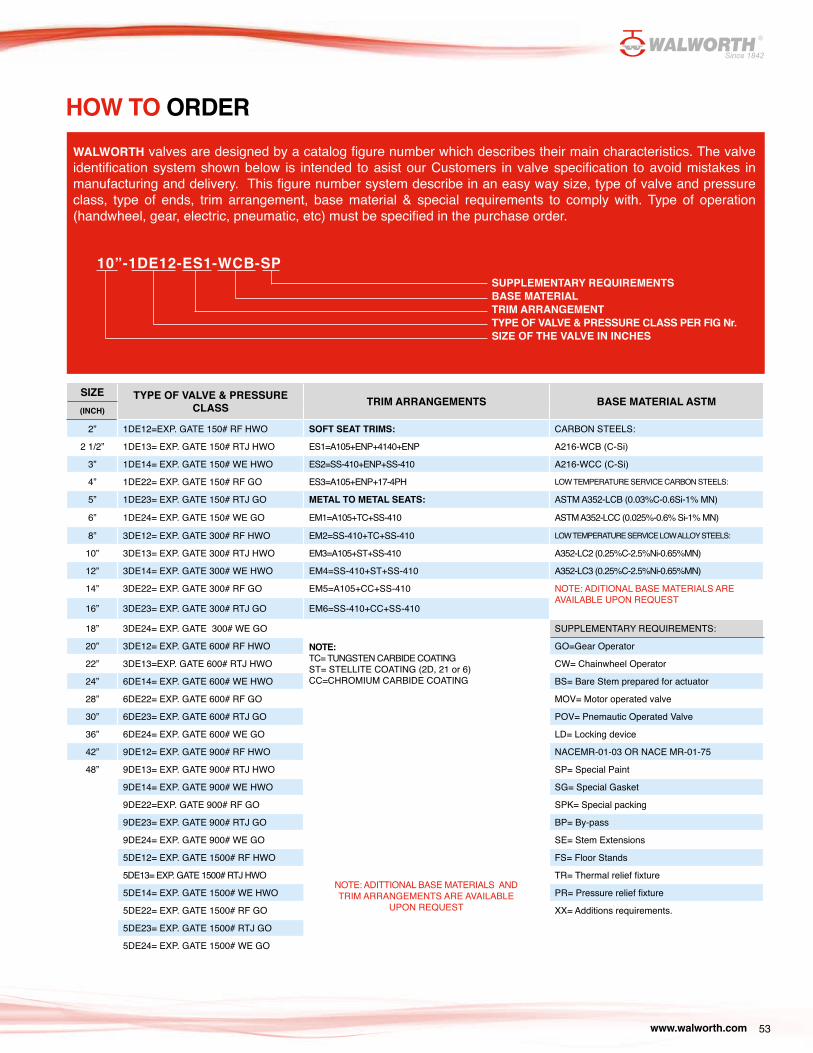
www.walworth.com 53
HOW TO ORDERWALWORTH valves are designed by a catalog figure number which describes their main characteristics. The valve identification system shown below is intended to asist our Customers in valve specification to avoid mistakes in manufacturing and delivery. This figure number system describe in an easy way size, type of valve and pressure class, type of ends, trim arrangement, base material & special requirements to comply with. Type of operation (handwheel, gear, electric, pneumatic, etc) must be specified in the purchase order.
10”-1DE12-ES1-WCB-SPSUPPLEMENTARY REQUIREMENTSBASE MATERIALTRIM ARRANGEMENTTYPE OF VALVE & PRESSURE CLASS PER FIG Nr.SIZE OF THE VALVE IN INCHES
SIZE TYPE OF VALVE & PRESSURE CLASS TRIM ARRANGEMENTS BASE MATERIAL ASTM
(INCH)
2” 1DE12=EXP. GATE 150# RF HWO SOFT SEAT TRIMS: CARBON STEELS:
2 1/2” 1DE13= EXP. GATE 150# RTJ HWO ES1=A105+ENP+4140+ENP A216-WCB (C-Si)
3” 1DE14= EXP. GATE 150# WE HWO ES2=SS-410+ENP+SS-410 A216-WCC (C-Si)
4” 1DE22= EXP. GATE 150# RF GO ES3=A105+ENP+17-4PH LOW TEMPERATURE SERVICE CARBON STEELS:
5” 1DE23= EXP. GATE 150# RTJ GO METAL TO METAL SEATS: ASTM A352-LCB (0.03%C-0.6Si-1% MN)
6” 1DE24= EXP. GATE 150# WE GO EM1=A105+TC+SS-410 ASTM A352-LCC (0.025%-0.6% Si-1% MN)
8” 3DE12= EXP. GATE 300# RF HWO EM2=SS-410+TC+SS-410 LOW TEMPERATURE SERVICE LOW ALLOY STEELS:
10” 3DE13= EXP. GATE 300# RTJ HWO EM3=A105+ST+SS-410 A352-LC2 (0.25%C-2.5%Ni-0.65%MN)
12” 3DE14= EXP. GATE 300# WE HWO EM4=SS-410+ST+SS-410 A352-LC3 (0.25%C-2.5%Ni-0.65%MN)
14” 3DE22= EXP. GATE 300# RF GO EM5=A105+CC+SS-410 NOTE: ADITIONAL BASE MATERIALS AREAVAILABLE UPON REQUEST
16” 3DE23= EXP. GATE 300# RTJ GO EM6=SS-410+CC+SS-410
18” 3DE24= EXP. GATE 300# WE GO SUPPLEMENTARY REQUIREMENTS:
20” 3DE12= EXP. GATE 600# RF HWO NOTE: TC= TUNGSTEN CARBIDE COATINGST= STELLITE COATING (2D, 21 or 6)CC=CHROMIUM CARBIDE COATING
GO=Gear Operator
22” 3DE13=EXP. GATE 600# RTJ HWO CW= Chainwheel Operator
24” 6DE14= EXP. GATE 600# WE HWO BS= Bare Stem prepared for actuator
28” 6DE22= EXP. GATE 600# RF GO MOV= Motor operated valve
30” 6DE23= EXP. GATE 600# RTJ GO POV= Pnemautic Operated Valve
36” 6DE24= EXP. GATE 600# WE GO LD= Locking device
42” 9DE12= EXP. GATE 900# RF HWO NACEMR-01-03 OR NACE MR-01-75
48” 9DE13= EXP. GATE 900# RTJ HWO SP= Special Paint
9DE14= EXP. GATE 900# WE HWO SG= Special Gasket
9DE22=EXP. GATE 900# RF GO SPK= Special packing
9DE23= EXP. GATE 900# RTJ GO BP= By-pass
9DE24= EXP. GATE 900# WE GO SE= Stem Extensions
5DE12= EXP. GATE 1500# RF HWO FS= Floor Stands
5DE13= EXP. GATE 1500# RTJ HWO TR= Thermal relief fixture
5DE14= EXP. GATE 1500# WE HWO PR= Pressure relief fixture
5DE22= EXP. GATE 1500# RF GO XX= Additions requirements.
5DE23= EXP. GATE 1500# RTJ GO
5DE24= EXP. GATE 1500# WE GO
NOTE: ADITTIONAL BASE MATERIALS ANDTRIM ARRANGEMENTS ARE AVAILABLE
UPON REQUEST
www.walworth.com54
THE WALWORTH COMPANY GENERAL TERMS AND CONDITIONS
ACCEPTANCE: All quotations are for acceptance within 30 days from date of quotation unless extended in writing. In the event a purchase order is placed after this period of time, the WALWORTH Company reserves the right to requote base prices of all valves offered. All orders and contracts are subject to credit approval and acceptance by the WALWORTH Company.
FREIGHT: When prices are f.o.b. point of shipment - no freight allowance - we will attempt to route shipments in the method which will result in the lowest cost unless otherwise instructed. All shipments will be freight charges collect except when stipulated on the purchase order, in which case you will be invoiced for all transportation charges. Delivery of material to a common carrier shall be considered to be delivery to Buyer and shall be at Buyer’s risk thereafter. Claims of loss of or damage to material in transit shall be filed by the Buyer directly with the carrier.
PRICES: There will be added to all prices quoted sales, use, occupation or any other excise or similar tax which Seller may be required to pay or collect on or in connection with the sale. Seller shall be established by Federal, State or other government regulation with respect to the product(s) topped by the order which shall be lower than the price(s) specified in the order.
ESCALATION TERMS: Prices shown in this price schedule reflect the costs in effect at the time of publication. These prices will remain firm on all products with a quoted delivery of twenty–six (26) weeks or less. On products which have a scheduled delivery of more than twenty-six (26) weeks, the goods will be invoiced based on the applicable price sheet in effect at the time of shipment. In no event will the invoiced price be less than the price originally quoted.
PURCHASED COMPONENTS: (i.e. motors, gearing, etc.) Prices are quoted on the supplier’s price in effect at the time of quotation. Actual invoice price will be adjusted in accordance with the supplier’s escalation policy.
DIFFERED SHIPMENTS: If for any reason the customer desires to delay shipments more than 30 days after manufacturing is complete, or to place a on hold or stop to the order during the manufacturing cycle, The WALWORTH Company reserves the right to consider the order cancelled and to invoke cancellation charges per the schedule bellow.
CANCELLATION: After order acceptance by WALWORTH, items or completed orders may be cancelled and Buyer will be charged for work performed, based on the following schedule:
- Five percent (5%) of prices of stock items.- Ten percent (10%) of price of stock items ordered in quantities which exceednormal inventory levels.- Five percent (5%) of prices prior to drawing submittal on made-to-order items.- 15% after drawing approval, but prior to the start of castings.- 30% to 50% during casting cycle, depending on the state of completion.- 55% to 75% during machining and assembly operations, depending on thestate of completion.-100% after final assembly and test.
REMITTANCES: Remittances must be made to the address indicated on theinvoice.
CREDIT TERMS: As quoted. Invoices on balances overdue will be subject to a service charge of 1 1/2 % per month on such indebtedness.
DELIVERIES: Shipments and deliveries shall at all times be subject to the approval of Seller’s Credit Department. If the Buyer shall fail to make any
payments according to the terms of the contract, Seller may, in addition to and not in limitation of its other rights and remedies, at its option, cancel all or any part of Buyer’s incomplete contracts with Seller, or may defer shipments of deliveries under Buyer’s contracts with Seller except upon receipt of satisfactory security or for cash shipment.
All schedule of shipments are estimated as closely as possible and Seller will use its best efforts to ship within the time scheduled, but does not guarantee to do so. Schedules commence with the date Seller receives authorization to proceed with the order, subject to the provisions of the next sentence. The order will not be released for manufacture until complete specifications and approved drawings (if drawing approval is required) are received at the plant of manufacturer and the estimated schedule of shipment will commence with the date of such receipt.
Seller shall not be liable for any direct, indirect or consequential damage or loss caused by any delay in delivery, regardless of the cause of delay.
Without limiting the generality of the foregoing, Seller assumes no responsibility for delays in delivery resulting from fire, flood, accidents, riots, strikes, transportation delays, labor or material shortages, existing or future laws, acts of any governmental authority, or any other cause beyond Seller’s control. Items offered from stock are subject to prior sale.
INSPECTION: Final inspection and acceptance of products must be made at the plant of manufacture, unless otherwise provided in the order and/ or in agreed upon specifications. Prices do not include charges for special tests or inspections performed at the request of the Buyer, unless called for in the order and/or in agreed upon specifications.
RETURNS: Permission in writing and return tagging instructions must be obtained from Seller before any goods returned for credit or adjustment will be accepted. Where returned goods are accepted, a minimum charge of 25% of the invoice price will be made, plus freight from both directions and costs of reconditioning the material for resale as new.
WARRANTY: Seller will replace without charge or refund the purchase price of products manufactured by Seller which prove to be defective in the material or workmanship, provided in each case that the product is properly installed and is used in the service for which Seller recommends it and that a written claim, specifying the alleged defect, is presented to Seller. Seller shall in no event be responsible for (a) claims for labor, expenses or other damages occasioned by defective products or (b) for consequences or secondary damages. THE WARRANTY STATED IN THIS PARAGRAPH IS IN LIEU OF ALL OTHER WARRANTIES, EITHER EXPRESSED OR IMPLIED. WITH RESPECT TO WARRANTIES, THIS PARAGRAPH STATES BUYER’S EXCLUSIVE REMEDY AND SELLER’S EXCLUSIVE LIABILITY.
DESIGN, ETC: Seller reserves the right to change design, materials or specifications without notice. There will be a charge for modifying an order after it has been entered when such change or modification results in additional engineering or clerical work for either The WALWORTH Company or our suppliers.
MINIMUM CHARGE: Orders totaling less than $100.00 net will be billed at a minimum charge of $100.00. Repair parts will be billed at a minimum charge of $50.00.
NOTE: We reserve the right to correct obvious clerical errors in quotations, invoices, and other contracts.

www.walworth.com
USA/CAN AUTHORIZED DISTRIBUTOR
TWC The Valve Company13641 Dublin Court, Stafford, Texas 77477 | Phone: (281) 566 1200 Fax: (281) 566 1299 |
www.twcvalves.com | e-mail: [email protected]
MÉXICO
Industrial de Válvulas, S.A. de C.V. Industria Lote 16 Sin Número, Fracc. Industrial El Trébol De Tepotzotlán, Tepotzotlán Estado de México C.P. 54610
Phone: (52 55) 5899 1700 Fax: (52 55) 5876 0156 | e-mail: [email protected]
Scan me with your smartphone to get more info about WALWORTH valves
EXPANDING GATE VALVES | 2016 EDITION | VERSION 2
Related Documents