ExoWear Medical Fitness Device Final Report Mengda Qi, Titus Fong, Caleb Klaus TA: James Norton ECE 445 Senior Design Spring 2016

Welcome message from author
This document is posted to help you gain knowledge. Please leave a comment to let me know what you think about it! Share it to your friends and learn new things together.
Transcript

ExoWear Medical Fitness Device
Final Report
Mengda Qi, Titus Fong, Caleb Klaus
TA: James Norton
ECE 445 Senior Design
Spring 2016

Abstract
We designed and created a medical fitness device that tracks medical exercises, provides
realtime feedback and analytics, and seeks to improve patient compliance. A patient straps the
device to his leg before a home physical therapy session and pairs it with his computer. While
the exercise is being performed, the device’s sensors capture acceleration and rotation data from
the user’s movements which is then modeled for visualization on a computer screen. An
animated bar on the screen simultaneously displays the correct motion for an exercise chosen by
the user that provides guidance and helps the user perform the exercise correctly. The device is
powered by an embedded rechargeable battery and can be charged with a standard mini USB
cable. This project received 3rd place in the 2016 Cozad New Venture Competition and has been
accepted into the 20162017 iVenture, Polsky, and Summer@CIE Accelerators for further
development.
1

Table of Contents
1. Introduction i. Motivation p3 ii. Objectives p3 iii. Benefits p4 iv. Functions & Features p4
2. Design i. Overview p5 ii. Control Subsystem p6
(1) Microcontroller p6 (2) Wireless Communication p7
iii. Sensors Subsystem p8 (1) IMU sensor p8
iv. Power Subsystem p8 (1) Charging Circuit p11 (2) Power Switching Circuit p11 (3) Buck Converter p12 (4) Undervoltage Lockout p12
v. Microcontroller Software p12 vi. 3D Modeling Software p15
3. Design Verification i. Overview p15 ii. Inertial Measurement Unit p15
4. Cost i. Labor: p16 ii. Parts List: p16
5. Conclusions i. Accomplishments p17 ii. Uncertainties p18 iii. Ethical Considerations p18 iv. Future Work p19
References p20 Appendix A: Additional Figures p21 Appendix B: Requirements and Verification p25
2

1. Introduction
i. Motivation
There is currently a shortage of 30,000 physical therapist and a projected continual undersupply
of physical therapist for at least another 4 years [1]. There are over 13.6 million Americans with
shoulder pain [2] (2003) and 52.5 million Americans with arthritis [3] (2012). With the
Affordable Care Act, the “essential health benefits” now extend to preventative and wellness
services, chronic disease management, and rehabilitative and habilitative services and devices
including physical therapy. That is why there is more outpatient physical therapy than ever
before. Barriers to physical therapy treatment adherence can stem from multiple sources like,
low physical activity levels, low selfefficacy, barriers to exercise, and low social support [4].
We have identified the following 2 sub problems that result from the barriers mentioned above.
First, the end user (patients) find it difficult to remember how to perform their medical exercises
correctly and as a result, neglect to do them on a regular basis. Secondly, patients lack the
motivation to perform their medical exercises [5]. (Patient compliance can be as low as 30%) [6]
Additionally, currently there is no way for physicians or physical therapist to monitor their
patient’s physical therapy progress at home without actually being there. Medicare home health
rates for 2014 is $132.40 per physical therapist visit [7].
ii. Objectives
We recognize that the shortage of physicians can be solved in one of two ways. Either increase
the number of physicians, or increase the amount of work each physician can do. We will focus
on the latter option. By providing better technology, the amount of time needed on each patient
should decrease, thereby increasing the amount of patients each physician can help. Physical
therapy for knee rehab consists of a set of exercises. Here we concentrate on the development of
a prototype system to help users do 2 of these exercises, straight leg raise and leg extensions [8].
The reason for this is because the first 3 months out of a 9 month rehabilitation plan includes the
strengthening exercises mentioned above [9].
3

Patients often have to perform over six different types of exercise at different intervals
throughout the day. This can easily overwhelm patients who already have a full day of work and
as a result patients find themselves not practicing their exercises at all. We are lowering the
barriers for patients by showing a simulation of the correct exercise while the patient performs
the exercise. For our project this will be a basic simulation of the straight leg raise and leg
extension, which the user will attempt to follow. The smartphone or PC will be next to the
patient while they perform their exercises so they can easily view the simulation and their own
motion on the screen and adjust their motion if they are falling behind or going too fast.
iii. Benefits
● Patient motivated to do exercises
● Convenience Nonintrusive, lightweight device that can be easily strapped on
● Realtime motion displayed on PC with training motion to guide user during exercise
● Physical therapist can analyze results for a better holistic understanding of patient’s rehab
iv. Functions & Features
● Real time motion tracking by IMU sensors
● On board intermediate data processing
● Bluetooth module which enables wireless data transfer between device and PC
● Microcontroller which handles communication between sensors and bluetooth module
● PC app which receives and models the data
● Rechargeable battery and power circuit
4

2. Design
Figure 1. System Overview
i. Overview
Our overall system design is shown in figure 1. This project consists of three device subsystems,
Control, Sensor, and Power, and two software modules Microcontroller Software, and 3D
Modeling Software. The physical device (figure 6) was designed on a single PCB (figure 10)
with breakout boards for the sensor subsystem. It will strap onto the user’s leg with velcro straps,
with one sensor above the knee, and one at the ankle. An illustration of the user performing a
knee exercise with the device strapped on is shown in figure 8.
5

ii. Control Subsystem
The control subsystem (figure 2) manages the wireless communication between the mobile
device and the microcontroller. It consists of a microcontroller, a bluetooth low energy module, a
status LED, and a push button for powering and resetting the device.
Figure 2. Control and Seniors Schematic
(1) Microcontroller
Inputs:
a. 3.3 V from power supply
b. IMU sensor data (I2C interface)
c. Bluetooth module data (SPI interface)
d. Push button switch
Purpose:
a. The microcontroller is the hub of the device. It will control the state of the IMU
sensors (transmitting data or not) and will determine the frequency of acceleration
6

and rotation data collection. The microcontroller will also control the state of the
bluetooth module, and transmit data from the IMU to the bluetooth module. It will
also receive input from the push button for powering on, powering off, and
resetting the system. It will provide device status through a LED, which will show
if the device is on or off, as well as whether it is actively transmitting data or not.
Outputs:
a. IMU control signals (I2C interface)
b. Bluetooth control signals (SPI interface)
c. Acceleration and rotational data to bluetooth module
d. LED indicator
(2) Wireless Communication
Inputs:
a. 3.3 V from power supply
b. Microcontroller data (SPI interface)
c. PC device data (Bluetooth protocol)
Purpose:
a. The wireless communication block is a single bluetooth transmitter that will allow
acceleration and rotation data to be transferred from the wearable device to the PC
device. Acceleration and rotation data received from the microcontroller will be
sent to the PC device through the bluetooth protocol. Data from the PC, such as
control signals to shut down the device then need to be transferred back. The
wireless communication module will also be able to receive and send this data to
the microcontroller.
Outputs:
a. PC device
b. Microcontroller
7
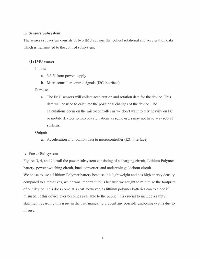
iii. Sensors Subsystem
The sensors subsystem consists of two IMU sensors that collect rotational and acceleration data
which is transmitted to the control subsystem.
(1) IMU sensor
Inputs:
a. 3.3 V from power supply
b. Microcontroller control signals (I2C interface)
Purpose
a. The IMU sensors will collect acceleration and rotation data for the device. This
data will be used to calculate the positional changes of the device. The
calculations occur on the microcontroller as we don’t want to rely heavily on PC
or mobile devices to handle calculations as some users may not have very robust
systems.
Outputs:
a. Acceleration and rotation data to microcontroller (I2C interface)
iv. Power Subsystem
Figures 3, 4, and 9 detail the power subsystem consisting of a charging circuit, Lithium Polymer
battery, power switching circuit, buck converter, and undervoltage lockout circuit.
We chose to use a Lithium Polymer battery because it is lightweight and has high energy density
compared to alternatives, which was important to us because we sought to minimize the footprint
of our device. This does come at a cost, however, as lithium polymer batteries can explode if
misused. If this device ever becomes available to the public, it is crucial to include a safety
statement regarding this issue in the user manual to prevent any possible exploding events due to
misuse.
8

Figure 3. Power Subsystem Schematic
Figure 4. Buck Converter Schematic
9

There were two unknown resistor values we needed to calculate in figure 3. For the value of R2,
a simple V=IR calculation of 5V/470Ω ≈ 10mA which is sufficient to drive a red LED. The
value of R3 requires a more complex calculation since it depends on the intrinsic properties of
the pchannel mosfet transistor. The equation below shows the current supplied by a pchannel
transistor based on transistor characteristics.
Ideally, based on max current draw, ids should be at least 48 mA. Given the battery voltage of 3.7
V, the resistor should be around 75 Ω to draw 50 mA of current.
Table 1 shows the maximum current draw of each component as well as the resulting total
current draw of the device. The device should function for at least 5 hours under maximum usage
to ensure the user does not need to charge the device more than once a day. Assuming an
overhead of 100% (worst case scenario), the maximum current draw is 64mA. The following
power calculation yielded the maximum power draw of this device under 5 hours of usage.
5 hours * 64mA = 320mAh
Thus we needed a battery which had a capacity of at least 320mAh, and to be on the safe side we
chose a battery rated at 350mAh.
Device Max Current Draw
Microcontroller 12 mA
IMU A 4 mA
IMU B 4 mA
Bluetooth Module 12 mA
Total 32 mA
With 50% overhead 48 mA
10

With 100% overhead 64mA
Table 1. Current Draw
(1) Charging Circuit
Inputs:
a. 5 V DC from miniUSB
Purpose
a. The charging circuit will provide power to the control and sensor subsystems by
switching between battery and AC adapter as necessary. On normal operation,
where the device is unplugged from a 5V DC source, the charging circuit will
draw current from the rechargeable battery. If the battery has a low charge, the
low battery LED will light up to prompt the user to recharge the device.
Outputs:
a. Variable DC to recharge battery (current and voltage depend on charging
conditions)
b. LED to indicate low battery charge
(2) Power Switching Circuit
Inputs:
a. 5 V/0 V USB DC
b. 3.5 4.2 V Battery DC
Purpose
a. The power switching circuit is made up of a pchannel MOSFET and 2 diodes to
switch between either the battery or USB inputs. If the battery is charging, the
load should only draw from the 5 V source, and not the battery. The transistor
gate is controlled by the USB source. When the USB source is switched off, the
gate allows the current from the battery to flow through to the load.
Outputs:
a. 3.3 V Regulator
11

(3) Buck Converter
Inputs:
a. 3.3 V 5 V DC from battery or USB source
Purpose:
a. The buck converter should take in 3.3V 5V and output 3.3V to the rest of the
circuit. The buck converter should be at least 80% efficient to maximize battery
life. For the final PCB
Outputs:
a. 3.3 V DC
(4) Undervoltage Lockout
Inputs:
a. 05V DC from battery
Purpose:
a. The UVLO (figure 9) prevents battery usage when the battery drops below 3.5V
to prevent deep battery discharge. For lithium polymer batteries, deep discharge
can permanently damage the battery or reduce capacity over time. The UVLO
circuit has a comparator that controls a PMOS for switching the load on or off.
The comparator takes in the battery voltage and a compares it to a shunt
reference. When the battery voltage drops below the reference voltage, the
comparator switches the PMOS so that the load no longers draws current from the
battery. The UVLO circuit uses resistors in the megohm range to reduce current
draw for longer battery life. A simulation of the working UVLO is shown in
figure 8.
Outputs:
a. 3.54.2V DC from battery
12

v. Microcontroller Software
This software component takes in both the Digital Motion Processor (DMP) and raw data from
the two inertial measurement units (IMUs) and passes this data to the computer for further
processing. The software first sets up the connection baud rate for the bluetooth and initializes
the offsets for both IMUs. The software then goes into a loop every ten milliseconds for data
collection and passing. In the loop, the software requests quaternions, acceleration and euler
angle data from the fifo buffer in the IMUs and requests the bluetooth module to pass data on to
the PC. The software also calculates a 22 byte package (table 2) from the quaternions data for the
Processing software to graph the 3D model of the movement. To ensure stability, during every
loop the software checks the connection with the PC and IMUs, and will not update the 22 byte
package if either or both do not have a connection. The diagram for this is shown in figure 5.
13
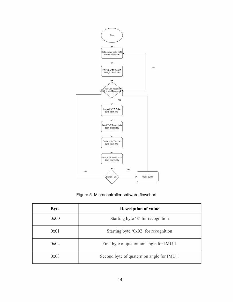
Figure 5. Microcontroller software flowchart
Byte Description of value
0x00 Starting byte ‘$’ for recognition
0x01 Starting byte ‘0x02’ for recognition
0x02 First byte of quaternion angle for IMU 1
0x03 Second byte of quaternion angle for IMU 1
14

0x04 First byte of quaternion X axis for IMU 1
0x05 Second byte of quaternion X axis for IMU 1
0x06 First byte of quaternion Y axis for IMU 1
0x07 Second byte of quaternion Y axis for IMU 1
0x08 First byte of quaternion Z axis for IMU 1
0x09 Second byte of quaternion Z axis for IMU 1
0x10 First byte of quaternion angle for IMU 2
0x11 Second byte of quaternion angle for IMU 2
0x12 First byte of quaternion X axis for IMU 2
0x13 Second byte of quaternion X axis for IMU 2
0x14 First byte of quaternion Y axis for IMU 2
0x15 Second byte of quaternion Y axis for IMU 2
0x16 First byte of quaternion Z axis for IMU 2
0x17 Second byte of quaternion Z axis for IMU 2
0x18 Ending byte ‘0x02’ for recognition
0x19 Packet count for processing
0x20 ‘\r’ carriage return for serial port
0x21 ‘\n’ newline for serial port
Bytes 0x020x17 will then be repeated as many times as necessary
Table 2. Data byte mapping for sensor data packet transmission via bluetooth
15

vi. 3D Modeling Software
This software component takes in the 22 byte quaternions data packet shown in table 2 and
draws the 3D model of the movement in Processing 3.0. The software uses OpenGL library for
drawing and toxic library for 3D model calculation. This software first draws the movement
guide which the user needs to follow in a red bar. Next, the software does calculations on the
quaternions bytes received from the bluetooth and draws the approximate position of the IMUs
from the quaternions data to show the patient movement. The screenshot of the straight leg raise
and leg extensions Processing model in action are shown in figures 12 and figure 13.
3. Design Verification
i. Overview
Design requirements and verification is detailed in Appendix B. Our System successfully
performed all the necessary functions.
ii. Inertial Measurement Unit
The most important part of our device is the IMU measurement, especially the Z axis which is
where both leg exercises revolve around. To verify the IMU performance of receiving the correct
euler degree data, we put the IMU in a flat and 90 degree position in the Z axis and verificated
the eugler degree we got. We got between 0.01 and 0.00 for the IMU in the flat position and
between 88.00 to 88.99 for the IMU in the 90 degree position of the Z axis. This is within 5%
accuracy which was required. The IMU moves according to the physical movement which was
visually verificated in the 3D modeling program, showing that it has no problem with smooth
data measurement.
4. Cost
16

i. Labor:
A lot of work went into our project in order to produce a working device. Table 3 shows the approximate cost of labor of our project.
Partner Hourly Rate Total Hours Total (x2.5)
Titus Fong $50 100 $12500
Mengda Qi $50 100 $12500
Caleb Klaus $50 100 $12500
Total $150 300 $37500
Table 3. Labor Costs
ii. Parts List:
This device consists of many components, each of which comes with a price. We sought to
balance price and convenience (availability, documentation, etc) when choosing parts. Table 4
lists the cost of the components which were used in our project.
Item Parts Quantity Unit Price Total
Microcontroller ATmega328P 1 $1.43 $1.43
Bluetooth Module nRF51822 2 $17.95 $35.9
Inertial Measurement Unit MPU6050 2 $39.95 $79.9
Charge Management
Controllers
MCP73831 1 $1.28 $1.28
17

Linear Regulator LM1117 1 $1.65 $1.65
Printed Circuit Board
(PCB)
Designed by us
Manufactured by PCBway
10 $6.65 $66.50
Protoboard 2 $5 $10
PMOS Transistor DMG1013UW 1 $0.99 $0.99
Total $153.7
3
Table 4. Parts List
Adding the total values of table 3 and table 4, the grand total cost of our project comes out to
$37,653.73.
5. Conclusions
i. Accomplishments
In conclusion, we successfully designed and created a health and fitness device that tracks
medical leg exercises. Our PCB successfully transmitted the movement data collected from the
IMUs to the PC. We are also successfully created a 3D animation with our software model on
PC. We meet all the requirement mentioned in the verification table. This project received 3rd
place in the 2016 Cozad New Venture Competition and has been accepted in the 20162017
iVenture, Polsky, and Summer@CIE Accelerator program for further development.
ii. Uncertainties
One of the challenges that we encountered was data processing and filtering. The data received
had problems with motion drafting. After some research on this problem, we were able to set the
offset of the IMU to address the drafting problem. The drafting in the IMU is now undetectable
18

by eye. We also encountered a system freezing problem. By clearing the buffer in IMU after
every single loop and lowing the sample rate, we were able to collect data continuously for at last
ten minutes.
iii. Ethical Considerations
Due to the fact we created a product which could be potentially harmful to the public because of
the use of electrical components, we accept responsibility in making decisions consistent with
the safety, health, and welfare of the public, and are committed to promptly disclose factors that
might endanger the public or the environment. Since this product is tied to the medical field,
appropriate federal and state regulations were followed. We worked with an external team to
ensure that all HIPAA rules were closely followed in terms of data storage and personal records
maintenance. We also followed the IEEE code of ethics in this project. We strived to be honest
in our estimates to the best of our knowledge, and were open to constructive criticism from our
professors, TAs, and peers. We did our best to not discriminate by considering all demographics
as our target customer. We were always willing to help out our colleagues when necessary and
offered our honest opinions through peer review to help them succeed.
iv. Future Work
The stability is one of the major issue that we have to address for future development as stated
above. The other work we will do in the future is to design a smaller PCB for the device for
normal usage since the device we have is too large. We printed a larger PCB to ensure all
components could be soldered easily. However we designed a more compact PCB (figure 11)
which can be printed in the future. We will also look into installing two bluetooth modules so
that the two IMUs do not have to link with each other to reduce the footprint of the device. We
will also develop a mobile app to keep tack of the patient improvement on these medical
exercises. This work will be done in the near future while we are participating in the 20162017
iVenture, Polsky, and Summer@CIE Accelerators. In our business plan, we are planning on
launching the product in the 3rd quarter of 2017 for hospital and clinic to use.
19

References 1. “A Model To Project The Supply And Demand Of Physical Therapists 20102020”. American Physical
Therapy Association. Web. 28 Feb. 2016 http://www.apta.org/WorkforceData/ModelDescriptionFigures/ 2. "ACSM | Fact Sheets." ACSM | Fact Sheets. Web. 28 Feb. 2016. https://www.acsm.org/publicinformation/brochuresfactsheets/factsheets 3. "ArthritisRelated Statistics." Centers for Disease Control and Prevention. Centers for Disease Control and
Prevention, 2016. Web. 28 Feb. 2016. http://www.cdc.gov/arthritis/data_statistics/arthritisrelatedstats.htm 4. "ArthritisRelated Statistics." Centers for Disease Control and Prevention. Centers for Disease Control and
Prevention, 2016. Web. 28 Feb. 2016.
20

http://www.cdc.gov/arthritis/data_statistics/arthritisrelatedstats.htm 5. Dr Campbell. “J Epidemiol Community Health 2001.” Web. 28 Feb. 2016 http://jech.bmj.com/content/55/2/132.full 6. "Result Filters." National Center for Biotechnology Information. U.S. National Library of Medicine. Web. 28
Feb. 2016. http://www.ncbi.nlm.nih.gov/pubmed/8234458 7. "Medicare Home Health Rates Set for 2014." Medicare Home Health Rates Set for 2014. Web. 28 Feb. 2016. http://www.asha.org/News/2013/MedicareHomeHealthRatesSetfor2014/ 8. “Knee Conditioning Program”. American Academy of Orthopaedic Surgeons. Web. 28 Feb. 2016 http://orthoinfo.aaos.org/PDFs/Rehab_Knee_6.pdf 9. “Steps to Success: A Guide to Knee Rehabilitation”. Carticel Web. 28 Feb. 2016 http://www.kneeclinic.info/download/Carticel_ACI_Rehabilitation_Guide.pdf 10. “Rotator Cuff and Shoulder Conditioning Program” American Academy of Orthopaedic Surgeons. Web. 28
Feb. 2016 http://orthoinfo.aaos.org/PDFs/Rehab_Shoulder_5.pdf 11. “Hip Conditioning Program” American Academy of Orthopaedic Surgeons. Web. 28 Feb. 2016 http://orthoinfo.aaos.org/PDFs/Rehab_Hip_3.pdf
Appendix A: Additional Figures
21

Figure 6. ExoWear Physical Device
Figure 7. Physical Application
22

Figure 8. UVLO Simulation
Figure 9. UVLO Schematic
23

Figure 10. PCB Design
Figure 11. Compact PCB 3D model
24

Figure 12. Leg Extension in 3D Processing
Figure 13. Leg Raise in 3D Processing
25

Appendix B: Requirements and Verification
Requirement Verification Points
Power
Buck Converter
1. From input of 5 V ±
0.2 V, output of 3.3 V
± 0.1 V with max load
of 100 mA
1. Verification Process for Item 1:
a. Attach 35 ohm resistor as load
b. Attach oscilloscope across load
c. Set NMOS gate voltage to 31.25 kHz
square wave with 59.375% duty cycle
d. Ensure output voltage remains
between 3.2 V and 3.4 V
10
Battery
1. Battery must store
350 mAh, ±30 mAh
tolerance, of charge
2. Battery must maintain
charge when device is
not in use. No
substantial current
leak (up to 10%
capacity in 5 days)
should occur.
3. Device functions for 5
1. Verification Process for Item 1:
a. Attach 5.5 ohm resistor bank as load
b. Measure I and V at 5 minute intervals
c. Terminate test when any Vcell 3.3 V
d. Perform midpoint Riemann
summation
e. Ensure 350 mAh, ±30 mAh extracted
2. Verification Process for Item 2:
a. Fully charge battery
b. Unplug charger from wall outlet
c. Allow to sit for 5 days
d. Measure cell voltages
e. Ensure battery has not discharged
beyond 10% of max value
3. Verification Process for Item 3:
3
26

hours
a. Fully charge battery
b. Unplug charger from wall outlet
c. Turn on device
d. Wait 5 hours
e. Ensure device still functions
Charger
1. Battery must fully
charge to 350 mAh
±30 mAh in less than
90 minutes
1. Verification Process for Item 1:
a. Unplug charger from wall outlet
b. Fully drain battery
c. Plug charger into wall outlet
d. Wait 90 minutes
e. Ensure battery contains 350 mAh,
±30 mAh
2
Under Voltage Lock Out
1. Battery is cut off from
the rest of the device
when battery voltage
drops below 3 V ± 0.1
V
1. Verification Process for Item 1:
a. Fully charge battery
b. Unplug charger from wall outlet
c. Connect battery to device
d. Wait until device powers off from
lack of power
e. Measure battery voltage
f. Ensure battery voltage is 3V ± 0.1 V
15
Power Switching Circuit
1. Voltage output
switches to 5 V ± 0.2
V when Vin source is
5 V ± 0.2 V
2. Voltage output
1. Verification Process for Item 1:
a. Allow the battery to be fully charged
b. Attach 5V ± 0.2 V DC voltage supply
to 5V Vin
c. Output from circuit should be 5V ±
0.2 V and current draw from battery
should be 0.1 mA≤
5
27

switches to 3.7 V ±
0.1 V when Vin
source is open
2. Verification Process for Item 2
a. Allow the battery to be fully charged
b. Remove Vin source
c. Ensure there is a 3.7V ± 0.1 V power
supply to the linear regulator from the
battery
Control
Wireless data transmission
1. Functions for 3.3 V
± 0.1 V for Vin
2. RF bluetooth range is
at least 5 meters
3. Wirelessly transmits
data at 115200 ± 1000
bps
1. Verification Process for Item 1:
a. Attach 200 ohm resistance between
leads
b. Request bluetooth RF broad (slave) to
send test data to computer (master)
c. Attach variable voltage supply to Vin
d. Sweep from 3.2 V to 3.4 V and
ensure digital output remains original
value
2. Verification Process for Item 2:
a. Request bluetooth RF broad (slave) to
send testing data to computer
(master)
b. Move from the computer (master) to
5 meter away and ensure digital
output remains of original value
3. Verification Process for Item 3:
a. Request bluetooth RF broad (slave) to
send test data to computer (master)
b. Send 115200 bits (14,400 bytes) of
data
2.5
28
c. After 1 second, ensure 115200 ±
1000 bits received by computer
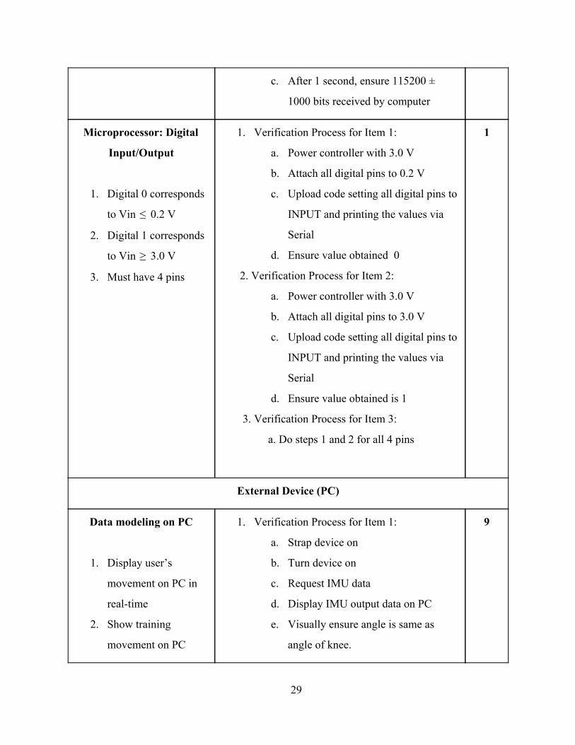
Microprocessor: Digital
Input/Output
1. Digital 0 corresponds
to Vin 0.2 V≤
2. Digital 1 corresponds
to Vin 3.0 V≥
3. Must have 4 pins
1. Verification Process for Item 1:
a. Power controller with 3.0 V
b. Attach all digital pins to 0.2 V
c. Upload code setting all digital pins to
INPUT and printing the values via
Serial
d. Ensure value obtained 0
2. Verification Process for Item 2:
a. Power controller with 3.0 V
b. Attach all digital pins to 3.0 V
c. Upload code setting all digital pins to
INPUT and printing the values via
Serial
d. Ensure value obtained is 1
3. Verification Process for Item 3:
a. Do steps 1 and 2 for all 4 pins
1
External Device (PC)
Data modeling on PC
1. Display user’s
movement on PC in
realtime
2. Show training
movement on PC
1. Verification Process for Item 1:
a. Strap device on
b. Turn device on
c. Request IMU data
d. Display IMU output data on PC
e. Visually ensure angle is same as
angle of knee.
9
29

which the user needs
to follow.
2. Verification Process for Item 2:
a. Display a bar which starts at 0
degrees
b. Verify bar slowly goes up to 90
degrees, then back to 0, and repeats
Sensors
Inertial measurement unit
1. Functions for 3.3 V ±
0.1 V for Vin
2. Rotational angle data
from the IMU is
within 5 degrees of
actual rotational angle
1. Verification Process for Item 1:
a. Attach 200 ohm resistance between
leads
b. Keep IMU still to simulate no motion
c. Attach variable voltage supply to Vin
d. Sweep from 3.2 V to 3.4 V and
ensure digital output remains at the
original value
2. Verification Process for Item 3:
a. Attach two IMU together at 0 degrees
angle
b. Request data from IMU for
accelerometer, angular rate sensor
and Digital Motion Processing data
c. Move IMUs with relation to each
other to create an angle
d. Measure the angle between the 2
IMUs with a protractor
e. Ensure the two IMUs have output
angular rate and Digital Motion
2.5
30

Processing angle values that are
within 5 degrees of the measured
angle
31
Related Documents