Copyright © 1998-2014, Sargent Manufacturing Company, an ASSA ABLOY Group company. All rights reserved. Reproduction in whole or in part without the express written permission of Sargent Manufacturing Company is prohibited. Exit Device Series 8 0

Welcome message from author
This document is posted to help you gain knowledge. Please leave a comment to let me know what you think about it! Share it to your friends and learn new things together.
Transcript
Copyright © 1998-2014, Sargent Manufacturing Company, an ASSA ABLOY Group company. All rights reserved. Reproduction in whole or in part without the express written permission of Sargent Manufacturing Company is prohibited.
Exit Device
Series80
80 Series
9064
1:P
6/1/
14
Copy
right
© 1
998-
2014
, Sar
gent
Man
ufac
turin
g Co
mpa
ny, a
n AS
SA A
BLO
Y G
roup
com
pany
. All
right
s res
erve
d.
Re
prod
uctio
n in
who
le o
r in
part
with
out t
he e
xpre
ss w
ritte
n pe
rmis
sion
of S
arge
nt M
anuf
actu
ring
Com
pany
is p
rohi
bite
d.
1-800-727-5477 • www.sargentlock.com
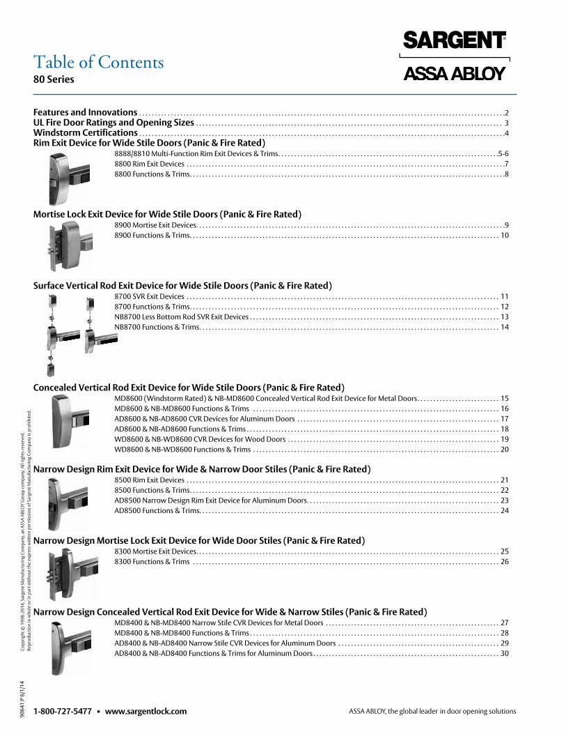
Features and Innovations . . . . . . . . . . . . . . . . . . . . . . . . . . . . . . . . . . . . . . . . . . . . . . . . . . . . . . . . . . . . . . . . . . . . . . . . . . . . . . . . . . . . . . . . . . . . . . . . . . . . . . . . . . . . . . . . . . . . 2UL Fire Door Ratings and Opening Sizes . . . . . . . . . . . . . . . . . . . . . . . . . . . . . . . . . . . . . . . . . . . . . . . . . . . . . . . . . . . . . . . . . . . . . . . . . . . . . . . . . . . . . . . . . . . . . . . . . 3Windstorm Certifications . . . . . . . . . . . . . . . . . . . . . . . . . . . . . . . . . . . . . . . . . . . . . . . . . . . . . . . . . . . . . . . . . . . . . . . . . . . . . . . . . . . . . . . . . . . . . . . . . . . . . . . . . . . . . . . . . . . .4Rim Exit Device for Wide Stile Doors (Panic & Fire Rated) 8888/8810 Multi-Function Rim Exit Devices & Trims . . . . . . . . . . . . . . . . . . . . . . . . . . . . . . . . . . . . . . . . . . . . . . . . . . . . . . . . . . . . . . . . . . . . . .5-6 8800 Rim Exit Devices . . . . . . . . . . . . . . . . . . . . . . . . . . . . . . . . . . . . . . . . . . . . . . . . . . . . . . . . . . . . . . . . . . . . . . . . . . . . . . . . . . . . . . . . . . . . . . . . . . . . .7 8800 Functions & Trims . . . . . . . . . . . . . . . . . . . . . . . . . . . . . . . . . . . . . . . . . . . . . . . . . . . . . . . . . . . . . . . . . . . . . . . . . . . . . . . . . . . . . . . . . . . . . . . . . . . .8
Mortise Lock Exit Device for Wide Stile Doors (Panic & Fire Rated) 8900 Mortise Exit Devices . . . . . . . . . . . . . . . . . . . . . . . . . . . . . . . . . . . . . . . . . . . . . . . . . . . . . . . . . . . . . . . . . . . . . . . . . . . . . . . . . . . . . . . . . . . . . . . . . .9 8900 Functions & Trims . . . . . . . . . . . . . . . . . . . . . . . . . . . . . . . . . . . . . . . . . . . . . . . . . . . . . . . . . . . . . . . . . . . . . . . . . . . . . . . . . . . . . . . . . . . . . . . . . . 10
Surface Vertical Rod Exit Device for Wide Stile Doors (Panic & Fire Rated) 8700 SVR Exit Devices . . . . . . . . . . . . . . . . . . . . . . . . . . . . . . . . . . . . . . . . . . . . . . . . . . . . . . . . . . . . . . . . . . . . . . . . . . . . . . . . . . . . . . . . . . . . . . . . . . . 11 8700 Functions & Trims . . . . . . . . . . . . . . . . . . . . . . . . . . . . . . . . . . . . . . . . . . . . . . . . . . . . . . . . . . . . . . . . . . . . . . . . . . . . . . . . . . . . . . . . . . . . . . . . . . 12 NB8700 Less Bottom Rod SVR Exit Devices . . . . . . . . . . . . . . . . . . . . . . . . . . . . . . . . . . . . . . . . . . . . . . . . . . . . . . . . . . . . . . . . . . . . . . . . . . . . . . . 13 NB8700 Functions & Trims . . . . . . . . . . . . . . . . . . . . . . . . . . . . . . . . . . . . . . . . . . . . . . . . . . . . . . . . . . . . . . . . . . . . . . . . . . . . . . . . . . . . . . . . . . . . . . . 14
Concealed Vertical Rod Exit Device for Wide Stile Doors (Panic & Fire Rated) MD8600 (Windstorm Rated) & NB-MD8600 Concealed Vertical Rod Exit Device for Metal Doors . . . . . . . . . . . . . . . . . . . . . . . . . . 15 MD8600 & NB-MD8600 Functions & Trims . . . . . . . . . . . . . . . . . . . . . . . . . . . . . . . . . . . . . . . . . . . . . . . . . . . . . . . . . . . . . . . . . . . . . . . . . . . . . . 16 AD8600 & NB-AD8600 CVR Devices for Aluminum Doors . . . . . . . . . . . . . . . . . . . . . . . . . . . . . . . . . . . . . . . . . . . . . . . . . . . . . . . . . . . . . . . . 17 AD8600 & NB-AD8600 Functions & Trims . . . . . . . . . . . . . . . . . . . . . . . . . . . . . . . . . . . . . . . . . . . . . . . . . . . . . . . . . . . . . . . . . . . . . . . . . . . . . . . . 18 WD8600 & NB-WD8600 CVR Devices for Wood Doors . . . . . . . . . . . . . . . . . . . . . . . . . . . . . . . . . . . . . . . . . . . . . . . . . . . . . . . . . . . . . . . . . . . 19 WD8600 & NB-WD8600 Functions & Trims . . . . . . . . . . . . . . . . . . . . . . . . . . . . . . . . . . . . . . . . . . . . . . . . . . . . . . . . . . . . . . . . . . . . . . . . . . . . . . 20
Narrow Design Rim Exit Device for Wide & Narrow Door Stiles (Panic & Fire Rated) 8500 Rim Exit Devices . . . . . . . . . . . . . . . . . . . . . . . . . . . . . . . . . . . . . . . . . . . . . . . . . . . . . . . . . . . . . . . . . . . . . . . . . . . . . . . . . . . . . . . . . . . . . . . . . . . 21 8500 Functions & Trims . . . . . . . . . . . . . . . . . . . . . . . . . . . . . . . . . . . . . . . . . . . . . . . . . . . . . . . . . . . . . . . . . . . . . . . . . . . . . . . . . . . . . . . . . . . . . . . . . . 22 AD8500 Narrow Design Rim Exit Device for Aluminum Doors . . . . . . . . . . . . . . . . . . . . . . . . . . . . . . . . . . . . . . . . . . . . . . . . . . . . . . . . . . . . . 23 AD8500 Functions & Trims . . . . . . . . . . . . . . . . . . . . . . . . . . . . . . . . . . . . . . . . . . . . . . . . . . . . . . . . . . . . . . . . . . . . . . . . . . . . . . . . . . . . . . . . . . . . . . . 24
Narrow Design Mortise Lock Exit Device for Wide Door Stiles (Panic & Fire Rated) 8300 Mortise Exit Devices . . . . . . . . . . . . . . . . . . . . . . . . . . . . . . . . . . . . . . . . . . . . . . . . . . . . . . . . . . . . . . . . . . . . . . . . . . . . . . . . . . . . . . . . . . . . . . . . 25 8300 Functions & Trims . . . . . . . . . . . . . . . . . . . . . . . . . . . . . . . . . . . . . . . . . . . . . . . . . . . . . . . . . . . . . . . . . . . . . . . . . . . . . . . . . . . . . . . . . . . . . . . . . 26
Narrow Design Concealed Vertical Rod Exit Device for Wide & Narrow Stiles (Panic & Fire Rated) MD8400 & NB-MD8400 Narrow Stile CVR Devices for Metal Doors . . . . . . . . . . . . . . . . . . . . . . . . . . . . . . . . . . . . . . . . . . . . . . . . . . . . . . . 27 MD8400 & NB-MD8400 Functions & Trims . . . . . . . . . . . . . . . . . . . . . . . . . . . . . . . . . . . . . . . . . . . . . . . . . . . . . . . . . . . . . . . . . . . . . . . . . . . . . . . 28 AD8400 & NB-AD8400 Narrow Stile CVR Devices for Aluminum Doors . . . . . . . . . . . . . . . . . . . . . . . . . . . . . . . . . . . . . . . . . . . . . . . . . . . 29 AD8400 & NB-AD8400 Functions & Trims for Aluminum Doors . . . . . . . . . . . . . . . . . . . . . . . . . . . . . . . . . . . . . . . . . . . . . . . . . . . . . . . . . . . 30
Table of Contents
80 Series
9064
1:P
6/1/
14
Copy
right
© 1
998-
2014
, Sar
gent
Man
ufac
turin
g Co
mpa
ny, a
n AS
SA A
BLO
Y G
roup
com
pany
. All
right
s res
erve
d.
Re
prod
uctio
n in
who
le o
r in
part
with
out t
he e
xpre
ss w
ritte
n pe
rmis
sion
of S
arge
nt M
anuf
actu
ring
Com
pany
is p
rohi
bite
d.
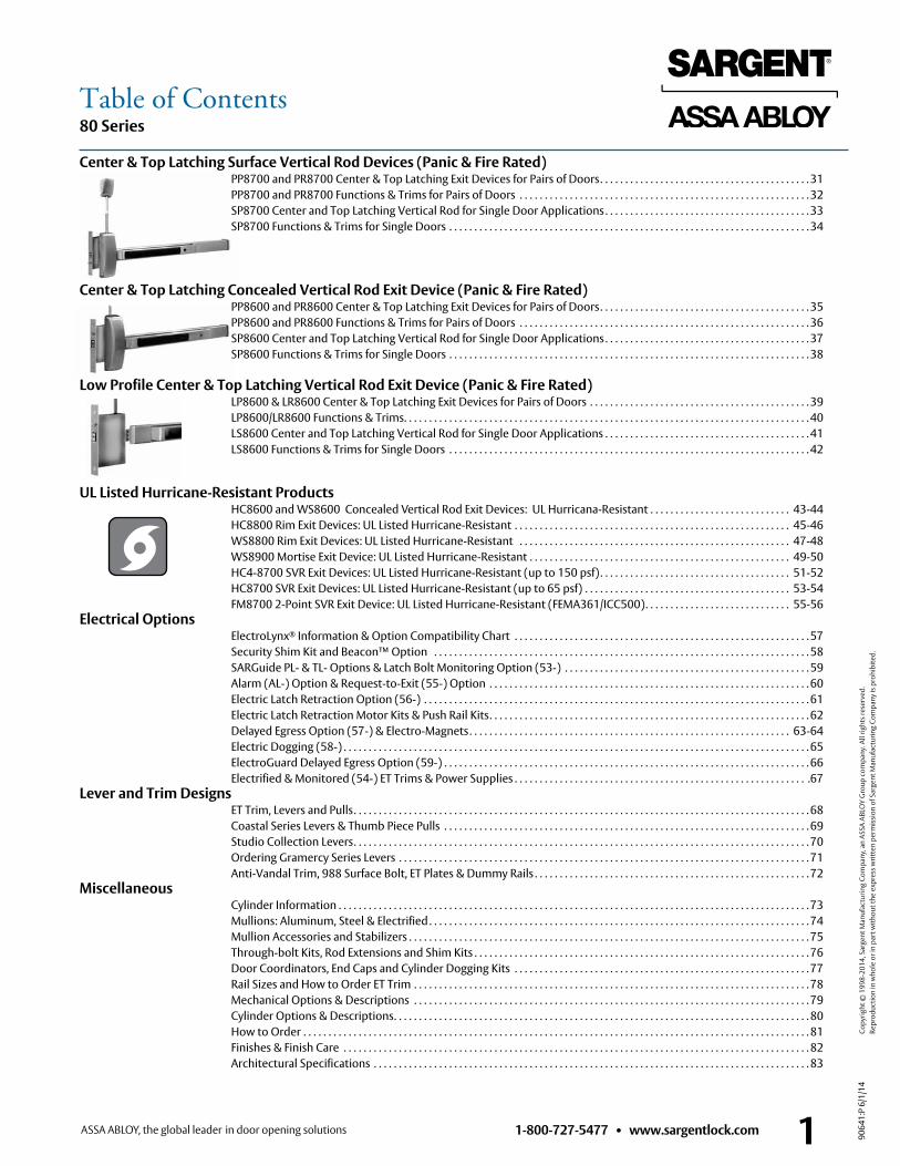
Center & Top Latching Surface Vertical Rod Devices (Panic & Fire Rated) PP8700 and PR8700 Center & Top Latching Exit Devices for Pairs of Doors . . . . . . . . . . . . . . . . . . . . . . . . . . . . . . . . . . . . . . . . . . 31 PP8700 and PR8700 Functions & Trims for Pairs of Doors . . . . . . . . . . . . . . . . . . . . . . . . . . . . . . . . . . . . . . . . . . . . . . . . . . . . . . . . . . 32 SP8700 Center and Top Latching Vertical Rod for Single Door Applications . . . . . . . . . . . . . . . . . . . . . . . . . . . . . . . . . . . . . . . . . 33 SP8700 Functions & Trims for Single Doors . . . . . . . . . . . . . . . . . . . . . . . . . . . . . . . . . . . . . . . . . . . . . . . . . . . . . . . . . . . . . . . . . . . . . . . . 34
Center & Top Latching Concealed Vertical Rod Exit Device (Panic & Fire Rated) PP8600 and PR8600 Center & Top Latching Exit Devices for Pairs of Doors . . . . . . . . . . . . . . . . . . . . . . . . . . . . . . . . . . . . . . . . . . 35 PP8600 and PR8600 Functions & Trims for Pairs of Doors . . . . . . . . . . . . . . . . . . . . . . . . . . . . . . . . . . . . . . . . . . . . . . . . . . . . . . . . . . 36 SP8600 Center and Top Latching Vertical Rod for Single Door Applications . . . . . . . . . . . . . . . . . . . . . . . . . . . . . . . . . . . . . . . . . 37 SP8600 Functions & Trims for Single Doors . . . . . . . . . . . . . . . . . . . . . . . . . . . . . . . . . . . . . . . . . . . . . . . . . . . . . . . . . . . . . . . . . . . . . . . . 38
Low Profile Center & Top Latching Vertical Rod Exit Device (Panic & Fire Rated) LP8600 & LR8600 Center & Top Latching Exit Devices for Pairs of Doors . . . . . . . . . . . . . . . . . . . . . . . . . . . . . . . . . . . . . . . . . . . . 39 LP8600/LR8600 Functions & Trims . . . . . . . . . . . . . . . . . . . . . . . . . . . . . . . . . . . . . . . . . . . . . . . . . . . . . . . . . . . . . . . . . . . . . . . . . . . . . . . . . 40 LS8600 Center and Top Latching Vertical Rod for Single Door Applications . . . . . . . . . . . . . . . . . . . . . . . . . . . . . . . . . . . . . . . . . 41 LS8600 Functions & Trims for Single Doors . . . . . . . . . . . . . . . . . . . . . . . . . . . . . . . . . . . . . . . . . . . . . . . . . . . . . . . . . . . . . . . . . . . . . . . . 42
UL Listed Hurricane-Resistant Products HC8600 and WS8600 Concealed Vertical Rod Exit Devices: UL Hurricana-Resistant . . . . . . . . . . . . . . . . . . . . . . . . . . . . 43-44 HC8800 Rim Exit Devices: UL Listed Hurricane-Resistant . . . . . . . . . . . . . . . . . . . . . . . . . . . . . . . . . . . . . . . . . . . . . . . . . . . . . . . 45-46 WS8800 Rim Exit Devices: UL Listed Hurricane-Resistant . . . . . . . . . . . . . . . . . . . . . . . . . . . . . . . . . . . . . . . . . . . . . . . . . . . . . . 47-48 WS8900 Mortise Exit Device: UL Listed Hurricane-Resistant . . . . . . . . . . . . . . . . . . . . . . . . . . . . . . . . . . . . . . . . . . . . . . . . . . . . 49-50 HC4-8700 SVR Exit Devices: UL Listed Hurricane-Resistant (up to 150 psf) . . . . . . . . . . . . . . . . . . . . . . . . . . . . . . . . . . . . . . 51-52 HC8700 SVR Exit Devices: UL Listed Hurricane-Resistant (up to 65 psf) . . . . . . . . . . . . . . . . . . . . . . . . . . . . . . . . . . . . . . . . . 53-54 FM8700 2-Point SVR Exit Device: UL Listed Hurricane-Resistant (FEMA361/ICC500) . . . . . . . . . . . . . . . . . . . . . . . . . . . . . 55-56Electrical Options ElectroLynx® Information & Option Compatibility Chart . . . . . . . . . . . . . . . . . . . . . . . . . . . . . . . . . . . . . . . . . . . . . . . . . . . . . . . . . . . 57 Security Shim Kit and Beacon™ Option . . . . . . . . . . . . . . . . . . . . . . . . . . . . . . . . . . . . . . . . . . . . . . . . . . . . . . . . . . . . . . . . . . . . . . . . . . . 58 SARGuide PL- & TL- Options & Latch Bolt Monitoring Option (53-) . . . . . . . . . . . . . . . . . . . . . . . . . . . . . . . . . . . . . . . . . . . . . . . . . 59 Alarm (AL-) Option & Request-to-Exit (55-) Option . . . . . . . . . . . . . . . . . . . . . . . . . . . . . . . . . . . . . . . . . . . . . . . . . . . . . . . . . . . . . . . . 60 Electric Latch Retraction Option (56-) . . . . . . . . . . . . . . . . . . . . . . . . . . . . . . . . . . . . . . . . . . . . . . . . . . . . . . . . . . . . . . . . . . . . . . . . . . . . . 61 Electric Latch Retraction Motor Kits & Push Rail Kits . . . . . . . . . . . . . . . . . . . . . . . . . . . . . . . . . . . . . . . . . . . . . . . . . . . . . . . . . . . . . . . . 62 Delayed Egress Option (57-) & Electro-Magnets . . . . . . . . . . . . . . . . . . . . . . . . . . . . . . . . . . . . . . . . . . . . . . . . . . . . . . . . . . . . . . . . 63-64 Electric Dogging (58-) . . . . . . . . . . . . . . . . . . . . . . . . . . . . . . . . . . . . . . . . . . . . . . . . . . . . . . . . . . . . . . . . . . . . . . . . . . . . . . . . . . . . . . . . . . . . . 65 ElectroGuard Delayed Egress Option (59-) . . . . . . . . . . . . . . . . . . . . . . . . . . . . . . . . . . . . . . . . . . . . . . . . . . . . . . . . . . . . . . . . . . . . . . . . . 66 Electrified & Monitored (54-) ET Trims & Power Supplies . . . . . . . . . . . . . . . . . . . . . . . . . . . . . . . . . . . . . . . . . . . . . . . . . . . . . . . . . . .67Lever and Trim Designs ET Trim, Levers and Pulls . . . . . . . . . . . . . . . . . . . . . . . . . . . . . . . . . . . . . . . . . . . . . . . . . . . . . . . . . . . . . . . . . . . . . . . . . . . . . . . . . . . . . . . . . . . 68 Coastal Series Levers & Thumb Piece Pulls . . . . . . . . . . . . . . . . . . . . . . . . . . . . . . . . . . . . . . . . . . . . . . . . . . . . . . . . . . . . . . . . . . . . . . . . . 69 Studio Collection Levers . . . . . . . . . . . . . . . . . . . . . . . . . . . . . . . . . . . . . . . . . . . . . . . . . . . . . . . . . . . . . . . . . . . . . . . . . . . . . . . . . . . . . . . . . . . 70 Ordering Gramercy Series Levers . . . . . . . . . . . . . . . . . . . . . . . . . . . . . . . . . . . . . . . . . . . . . . . . . . . . . . . . . . . . . . . . . . . . . . . . . . . . . . . . . . 71 Anti-Vandal Trim, 988 Surface Bolt, ET Plates & Dummy Rails . . . . . . . . . . . . . . . . . . . . . . . . . . . . . . . . . . . . . . . . . . . . . . . . . . . . . . . 72Miscellaneous Cylinder Information . . . . . . . . . . . . . . . . . . . . . . . . . . . . . . . . . . . . . . . . . . . . . . . . . . . . . . . . . . . . . . . . . . . . . . . . . . . . . . . . . . . . . . . . . . . . . . 73 Mullions: Aluminum, Steel & Electrified . . . . . . . . . . . . . . . . . . . . . . . . . . . . . . . . . . . . . . . . . . . . . . . . . . . . . . . . . . . . . . . . . . . . . . . . . . . . 74 Mullion Accessories and Stabilizers . . . . . . . . . . . . . . . . . . . . . . . . . . . . . . . . . . . . . . . . . . . . . . . . . . . . . . . . . . . . . . . . . . . . . . . . . . . . . . . . 75 Through-bolt Kits, Rod Extensions and Shim Kits . . . . . . . . . . . . . . . . . . . . . . . . . . . . . . . . . . . . . . . . . . . . . . . . . . . . . . . . . . . . . . . . . . . 76 Door Coordinators, End Caps and Cylinder Dogging Kits . . . . . . . . . . . . . . . . . . . . . . . . . . . . . . . . . . . . . . . . . . . . . . . . . . . . . . . . . . . 77 Rail Sizes and How to Order ET Trim . . . . . . . . . . . . . . . . . . . . . . . . . . . . . . . . . . . . . . . . . . . . . . . . . . . . . . . . . . . . . . . . . . . . . . . . . . . . . . . 78 Mechanical Options & Descriptions . . . . . . . . . . . . . . . . . . . . . . . . . . . . . . . . . . . . . . . . . . . . . . . . . . . . . . . . . . . . . . . . . . . . . . . . . . . . . . . 79 Cylinder Options & Descriptions . . . . . . . . . . . . . . . . . . . . . . . . . . . . . . . . . . . . . . . . . . . . . . . . . . . . . . . . . . . . . . . . . . . . . . . . . . . . . . . . . . . 80 How to Order . . . . . . . . . . . . . . . . . . . . . . . . . . . . . . . . . . . . . . . . . . . . . . . . . . . . . . . . . . . . . . . . . . . . . . . . . . . . . . . . . . . . . . . . . . . . . . . . . . . . . 81 Finishes & Finish Care . . . . . . . . . . . . . . . . . . . . . . . . . . . . . . . . . . . . . . . . . . . . . . . . . . . . . . . . . . . . . . . . . . . . . . . . . . . . . . . . . . . . . . . . . . . . . 82 Architectural Specifications . . . . . . . . . . . . . . . . . . . . . . . . . . . . . . . . . . . . . . . . . . . . . . . . . . . . . . . . . . . . . . . . . . . . . . . . . . . . . . . . . . . . . . . 83
1-800-727-5477 • www.sargentlock.com 1
Table of Contents
80 Series
9064
1:P
6/1/
14
Copy
right
© 1
998-
2014
, Sar
gent
Man
ufac
turin
g Co
mpa
ny, a
n AS
SA A
BLO
Y G
roup
com
pany
. All
right
s res
erve
d.
Re
prod
uctio
n in
who
le o
r in
part
with
out t
he e
xpre
ss w
ritte
n pe
rmis
sion
of S
arge
nt M
anuf
actu
ring
Com
pany
is p
rohi
bite
d.
1-800-727-5477 • www.sargentlock.com2
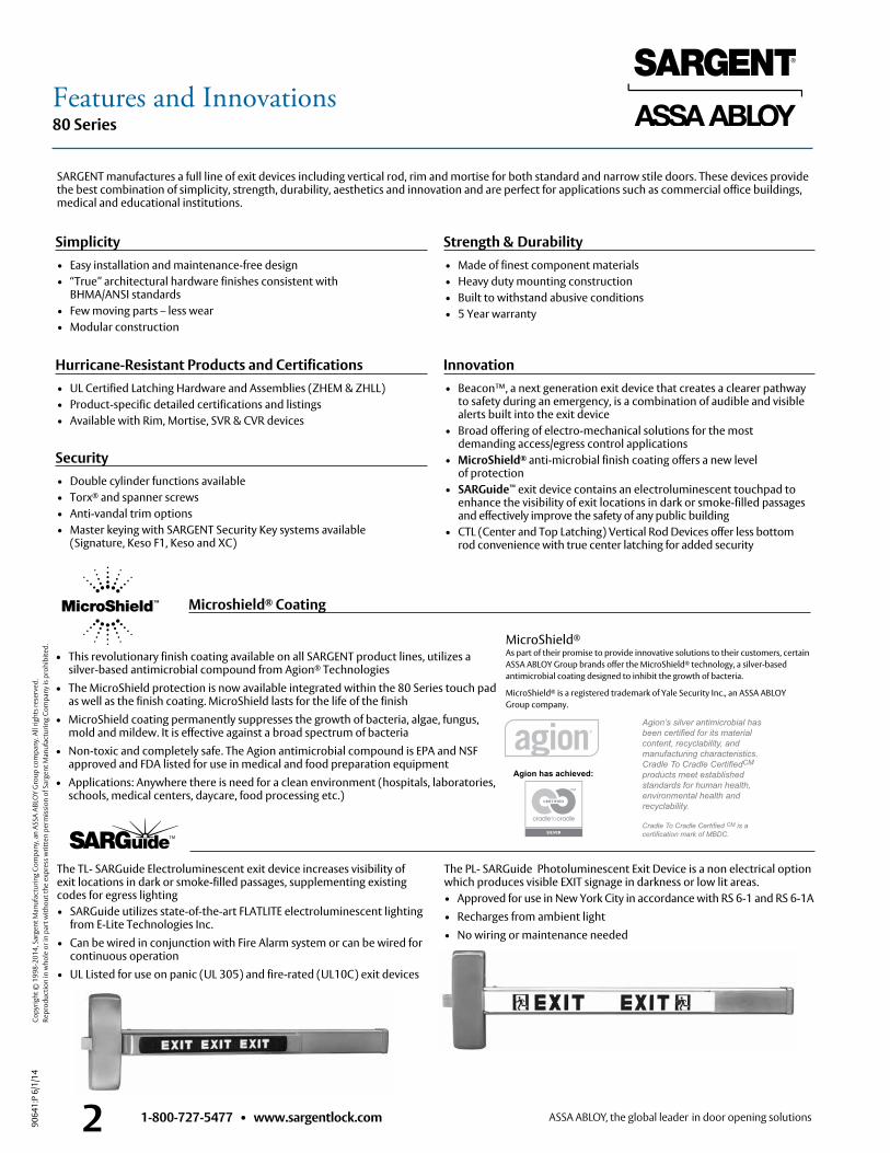
• This revolutionary finish coating available on all SARGENT product lines, utilizes a silver-based antimicrobial compound from Agion® Technologies
• The MicroShield protection is now available integrated within the 80 Series touch pad as well as the finish coating . MicroShield lasts for the life of the finish
• MicroShield coating permanently suppresses the growth of bacteria, algae, fungus, mold and mildew . It is effective against a broad spectrum of bacteria
• Non-toxic and completely safe . The Agion antimicrobial compound is EPA and NSF approved and FDA listed for use in medical and food preparation equipment
• Applications: Anywhere there is need for a clean environment (hospitals, laboratories, schools, medical centers, daycare, food processing etc .)
Strength & Durability• Made of finest component materials• Heavy duty mounting construction• Built to withstand abusive conditions• 5 Year warranty
SARGENT manufactures a full line of exit devices including vertical rod, rim and mortise for both standard and narrow stile doors . These devices provide the best combination of simplicity, strength, durability, aesthetics and innovation and are perfect for applications such as commercial office buildings, medical and educational institutions .
Innovation• Beacon™, a next generation exit device that creates a clearer pathway
to safety during an emergency, is a combination of audible and visible alerts built into the exit device
• Broad offering of electro-mechanical solutions for the most demanding access/egress control applications
• MicroShield® anti-microbial finish coating offers a new level of protection
• SARGuide™ exit device contains an electroluminescent touchpad to enhance the visibility of exit locations in dark or smoke-filled passages and effectively improve the safety of any public building
• CTL (Center and Top Latching) Vertical Rod Devices offer less bottom rod convenience with true center latching for added security
Security• Double cylinder functions available• Torx® and spanner screws• Anti-vandal trim options• Master keying with SARGENT Security Key systems available
(Signature, Keso F1, Keso and XC)
Microshield® Coating
The TL- SARGuide Electroluminescent exit device increases visibility of exit locations in dark or smoke-filled passages, supplementing existing codes for egress lighting• SARGuide utilizes state-of-the-art FLATLITE electroluminescent lighting
from E-Lite Technologies Inc .• Can be wired in conjunction with Fire Alarm system or can be wired for
continuous operation• UL Listed for use on panic (UL 305) and fire-rated (UL10C) exit devices
The PL- SARGuide Photoluminescent Exit Device is a non electrical option which produces visible EXIT signage in darkness or low lit areas .• Approved for use in New York City in accordance with RS 6-1 and RS 6-1A• Recharges from ambient light• No wiring or maintenance needed
Simplicity• Easy installation and maintenance-free design• “True” architectural hardware finishes consistent with
BHMA/ANSI standards• Few moving parts – less wear• Modular construction
Hurricane-Resistant Products and Certifications• UL Certified Latching Hardware and Assemblies (ZHEM & ZHLL)• Product-specific detailed certifications and listings• Available with Rim, Mortise, SVR & CVR devices
MicroShield®
As part of their promise to provide innovative solutions to their customers, certain ASSA ABLOY Group brands offer the MicroShield® technology, a silver-based antimicrobial coating designed to inhibit the growth of bacteria .
MicroShield® is a registered trademark of Yale Security Inc ., an ASSA ABLOY Group company .
Features and Innovations
80 Series
9064
1:P
6/1/
14
Copy
right
© 1
998-
2014
, Sar
gent
Man
ufac
turin
g Co
mpa
ny, a
n AS
SA A
BLO
Y G
roup
com
pany
. All
right
s res
erve
d.
Re
prod
uctio
n in
who
le o
r in
part
with
out t
he e
xpre
ss w
ritte
n pe
rmis
sion
of S
arge
nt M
anuf
actu
ring
Com
pany
is p
rohi
bite
d.
1-800-727-5477 • www.sargentlock.com 3Note: Please contact door manufacturer for specifications regarding fire door construction
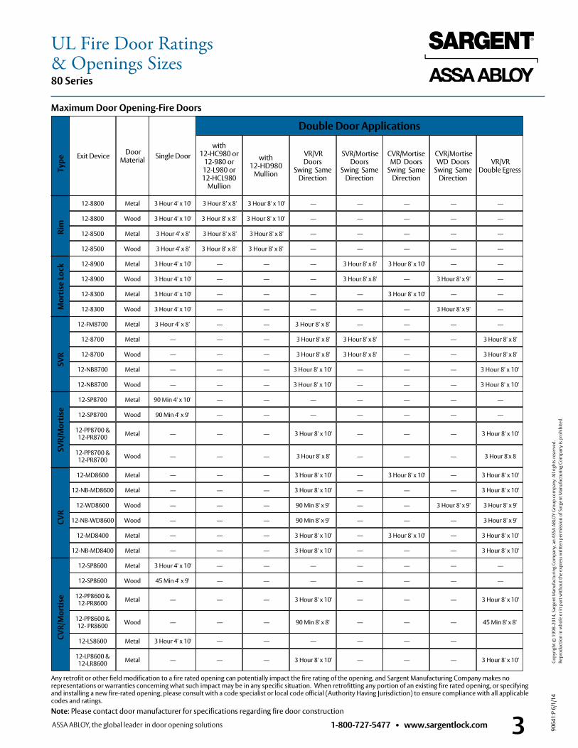
Maximum Door Opening-Fire Doors
Exit Device Door Material Single Door
Double Door Applications
with 12-HC980 or
12-980 or 12-L980 or 12-HCL980
Mullion
with12-HD980
Mullion
VR/VR Doors
Swing Same Direction
SVR/Mortise Doors
Swing Same Direction
CVR/Mortise MD Doors
Swing Same Direction
CVR/Mortise WD Doors
Swing Same Direction
VR/VR Double Egress
12-8800 Metal 3 Hour 4' x 10' 3 Hour 8’ x 8' 3 Hour 8' x 10' –– –– –– –– ––
12-8800 Wood 3 Hour 4' x 10' 3 Hour 8' x 8' 3 Hour 8' x 10' –– –– –– –– ––
12-8900 Metal 3 Hour 4' x 10' –– –– –– 3 Hour 8' x 8' 3 Hour 8' x 10' –– ––
12-8900 Wood 3 Hour 4' x 10' –– –– –– 3 Hour 8' x 8' –– 3 Hour 8' x 9' ––
12-8300 Metal 3 Hour 4' x 10' –– –– –– –– 3 Hour 8' x 10' –– ––
12-8300 Wood 3 Hour 4' x 10' –– –– –– –– –– 3 Hour 8' x 9' ––
12-FM8700 Metal 3 Hour 4' x 8' –– –– 3 Hour 8' x 8' –– –– –– ––
12-8700 Metal –– –– –– 3 Hour 8' x 8' 3 Hour 8' x 8' –– –– 3 Hour 8' x 8'
12-8700 Wood –– –– –– 3 Hour 8' x 8' 3 Hour 8' x 8' –– –– 3 Hour 8' x 8'
12-NB8700 Metal –– –– –– 3 Hour 8' x 10' –– –– –– 3 Hour 8' x 10'
12-NB8700 Wood –– –– –– 3 Hour 8' x 10' –– –– –– 3 Hour 8' x 10'
12-SP8700 Metal 90 Min 4' x 10' –– –– –– –– –– –– ––
12-SP8700 Wood 90 Min 4' x 9' –– –– –– –– –– –– ––
12-PP8700 & 12-PR8700 Metal –– –– –– 3 Hour 8' x 10' –– –– –– 3 Hour 8' x 10'
12-PP8700 & 12-PR8700 Wood –– –– –– 3 Hour 8' x 8' –– –– –– 3 Hour 8'x 8
12-MD8600 Metal –– –– –– 3 Hour 8' x 10' –– 3 Hour 8' x 10' –– 3 Hour 8' x 10'
12-NB-MD8600 Metal –– –– –– 3 Hour 8' x 10' –– –– –– 3 Hour 8' x 10'
12-WD8600 Wood –– –– –– 90 Min 8' x 9' –– –– 3 Hour 8' x 9' 3 Hour 8' x 9'
12-NB-WD8600 Wood –– –– –– 90 Min 8' x 9' –– –– –– 3 Hour 8' x 9'
12-MD8400 Metal –– –– –– 3 Hour 8' x 10' –– 3 Hour 8' x 10' –– 3 Hour 8' x 10'
12-NB-MD8400 Metal –– –– –– 3 Hour 8' x 10' –– –– –– 3 Hour 8' x 10'
12-SP8600 Metal 3 Hour 4' x 10' –– –– –– –– –– –– ––
12-SP8600 Wood 45 Min 4' x 9' –– –– –– –– –– –– ––
12-PP8600 & 12-PR8600 Metal –– –– –– 3 Hour 8' x 10' –– –– –– 3 Hour 8' x 10'
12-PP8600 & 12- PR8600 Wood –– –– –– 90 Min 8' x 8' –– –– –– 45 Min 8' x 8'
12-LS8600 Metal 3 Hour 4' x 10' –– –– –– –– –– ––
12-LP8600 & 12-LR8600 Metal –– –– –– 3 Hour 8' x 10' –– –– –– 3 Hour 8' x 10'
CVR
/Mor
tise
CVR
SVR
/Mor
tise
S
VR
M
ortis
e Lo
ck
R
im
Type
12-8500 Metal 3 Hour 4' x 8' 3 Hour 8' x 8' 3 Hour 8' x 8' –– –– –– –– ––
12-8500 Wood 3 Hour 4' x 8' 3 Hour 8' x 8' 3 Hour 8' x 8' –– –– –– –– ––
UL Fire Door Ratings& Openings Sizes
Any retrofit or other field modification to a fire rated opening can potentially impact the fire rating of the opening, and Sargent Manufacturing Company makes no representations or warranties concerning what such impact may be in any specific situation . When retrofitting any portion of an existing fire rated opening, or specifying and installing a new fire-rated opening, please consult with a code specialist or local code official (Authority Having Jurisdiction) to ensure compliance with all applicable codes and ratings .
1-800-727-5477 • www.sargentlock.com49064
1:P
6/1/
14
Copy
right
© 1
998-
2014
, Sar
gent
Man
ufac
turin
g Co
mpa
ny, a
n AS
SA A
BLO
Y G
roup
com
pany
. All
right
s res
erve
d.
Re
prod
uctio
n in
who
le o
r in
part
with
out t
he e
xpre
ss w
ritte
n pe
rmis
sion
of S
arge
nt M
anuf
actu
ring
Com
pany
is p
rohi
bite
d.
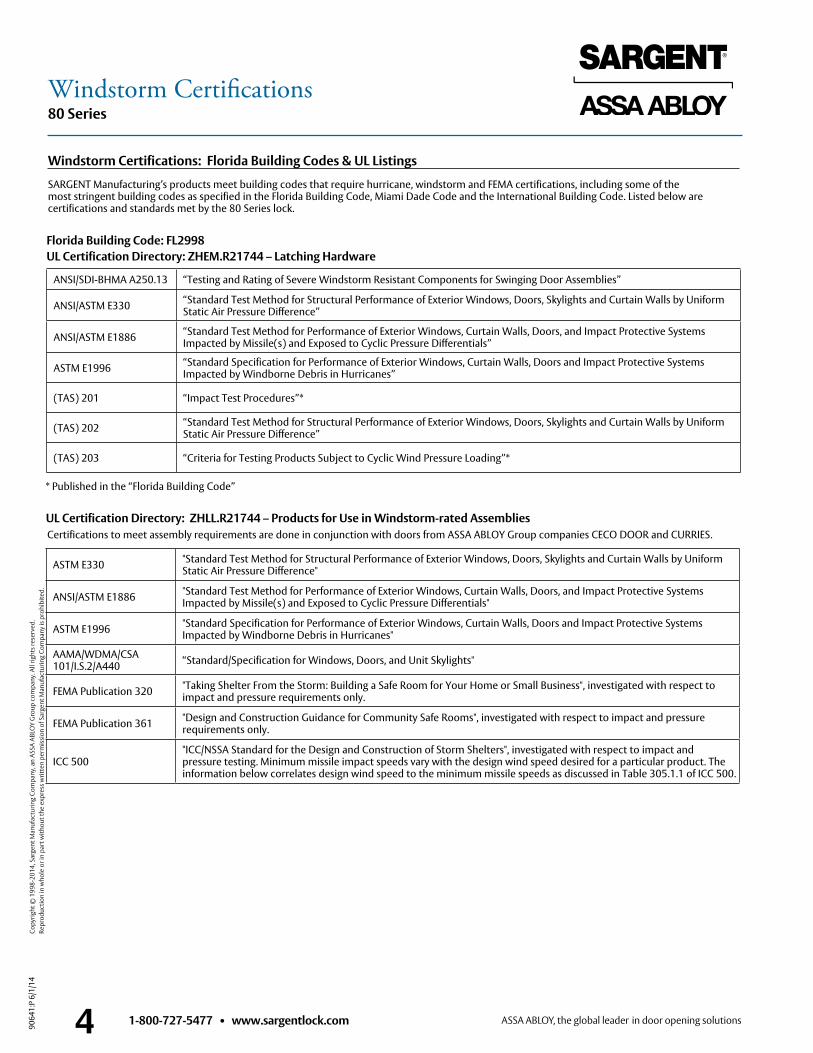
80 SeriesWindstorm Certifications
Florida Building Code: FL2998 UL Certification Directory: ZHEM.R21744 – Latching Hardware
UL Certification Directory: ZHLL.R21744 – Products for Use in Windstorm-rated Assemblies
ANSI/SDI-BHMA A250 .13 “Testing and Rating of Severe Windstorm Resistant Components for Swinging Door Assemblies”
ANSI/ASTM E330 “Standard Test Method for Structural Performance of Exterior Windows, Doors, Skylights and Curtain Walls by Uniform Static Air Pressure Difference”
ANSI/ASTM E1886 “Standard Test Method for Performance of Exterior Windows, Curtain Walls, Doors, and Impact Protective Systems Impacted by Missile(s) and Exposed to Cyclic Pressure Differentials”
ASTM E1996 “Standard Specification for Performance of Exterior Windows, Curtain Walls, Doors and Impact Protective Systems Impacted by Windborne Debris in Hurricanes”
(TAS) 201 “Impact Test Procedures”*
(TAS) 202 “Standard Test Method for Structural Performance of Exterior Windows, Doors, Skylights and Curtain Walls by Uniform Static Air Pressure Difference”
(TAS) 203 “Criteria for Testing Products Subject to Cyclic Wind Pressure Loading”*
ASTM E330 "Standard Test Method for Structural Performance of Exterior Windows, Doors, Skylights and Curtain Walls by Uniform Static Air Pressure Difference"
ANSI/ASTM E1886 "Standard Test Method for Performance of Exterior Windows, Curtain Walls, Doors, and Impact Protective Systems Impacted by Missile(s) and Exposed to Cyclic Pressure Differentials"
ASTM E1996 "Standard Specification for Performance of Exterior Windows, Curtain Walls, Doors and Impact Protective Systems Impacted by Windborne Debris in Hurricanes"
AAMA/WDMA/CSA 101/I .S .2/A440 “Standard/Specification for Windows, Doors, and Unit Skylights"
FEMA Publication 320 "Taking Shelter From the Storm: Building a Safe Room for Your Home or Small Business", investigated with respect to impact and pressure requirements only .
FEMA Publication 361 "Design and Construction Guidance for Community Safe Rooms", investigated with respect to impact and pressure requirements only .
ICC 500"ICC/NSSA Standard for the Design and Construction of Storm Shelters", investigated with respect to impact and pressure testing . Minimum missile impact speeds vary with the design wind speed desired for a particular product . The information below correlates design wind speed to the minimum missile speeds as discussed in Table 305 .1 .1 of ICC 500 .
SARGENT Manufacturing’s products meet building codes that require hurricane, windstorm and FEMA certifications, including some of the most stringent building codes as specified in the Florida Building Code, Miami Dade Code and the International Building Code . Listed below are certifications and standards met by the 80 Series lock .
Certifications to meet assembly requirements are done in conjunction with doors from ASSA ABLOY Group companies CECO DOOR and CURRIES .
Windstorm Certifications: Florida Building Codes & UL Listings
* Published in the “Florida Building Code”
1-800-727-5477 • www.sargentlock.com 5
80 Series
9064
1:P
6/1/
14
Copy
right
© 1
998-
2014
, Sar
gent
Man
ufac
turin
g Co
mpa
ny, a
n AS
SA A
BLO
Y G
roup
com
pany
. All
right
s res
erve
d.
Re
prod
uctio
n in
who
le o
r in
part
with
out t
he e
xpre
ss w
ritte
n pe
rmis
sion
of S
arge
nt M
anuf
actu
ring
Com
pany
is p
rohi
bite
d.
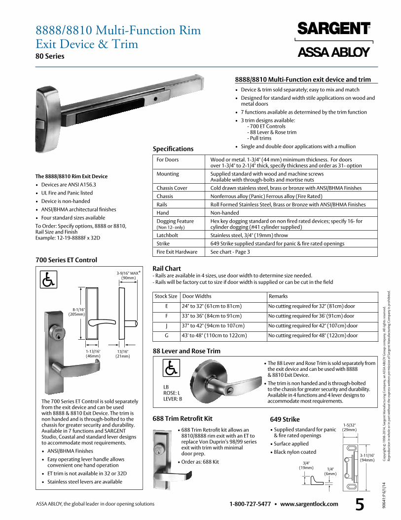
649 Strike• Supplied standard for panic
& fire rated openings• Surface applied• Black nylon coated
700 Series ET Control
The 700 Series ET Control is sold separately from the exit device and can be used with 8888 & 8810 Exit Device . The trim is non handed and is through-bolted to the chassis for greater security and durability . Available in 7 functions and SARGENT Studio, Coastal and standard lever designs to accommodate most requirements .
• ANSI/BHMA Finishes • Easy operating lever handle allows
convenient one hand operation • ET trim is not available in 32 or 32D • Stainless steel levers are available
For Doors Wood or metal . 1-3/4" (44 mm) minimum thickness . For doors over 1-3/4" to 2-1/4" thick, specify thickness and order as 31- option
Mounting Supplied standard with wood and machine screws Available with through-bolts and mortise nuts
Chassis Cover Cold drawn stainless steel, brass or bronze with ANSI/BHMA Finishes Chassis Nonferrous alloy (Panic) Ferrous alloy (Fire Rated) Rails Roll Formed Stainless Steel, Brass or Bronze with ANSI/BHMA Finishes Hand Non-handed Dogging Feature Hex key dogging standard on non fired rated devices; specify 16- for (Non 12- only) cylinder dogging (#41 cylinder supplied) Latchbolt Stainless steel, 3/4" (19mm) throw Strike 649 Strike supplied standard for panic & fire rated openings Fire Exit Hardware See chart - Page 3
LB ROSE: L LEVER: B
Specifications
13/16" (21mm)
1-13/16" (46mm)
8-1/16" (205mm)
3-9/16” MAX* (90mm)
8888/8810 Multi-Function exit device and trim• Device & trim sold separately; easy to mix and match• Designed for standard width stile applications on wood and
metal doors• 7 functions available as determined by the trim function• 3 trim designs available: - 700 ET Controls - 88 Lever & Rose trim - Pull trims• Single and double door applications with a mullion
Rail Chart - Rails are available in 4 sizes, use door width to determine size needed . - Rails will be factory cut to size if door width is supplied or can be cut in the field
The 8888/8810 Rim Exit Device• Devices are ANSI A156 .3• UL Fire and Panic listed• Device is non-handed• ANSI/BHMA architectural finishes• Four standard sizes availableTo Order: Specify options, 8888 or 8810, Rail Size and Finish Example: 12-19-8888F x 32D
3/4" (19mm) 1/4"
(6mm)
688 Trim Retrofit Kit
• 688 Trim Retrofit kit allows an 8810/8888 rim exit with an ET to replace Von Duprin’s 98/99 series exit with trim with minimal door prep .
• Order as: 688 Kit
Stock Size Door Widths Remarks
E 24" to 32" (61cm to 81cm) No cutting required for 32" (81cm) door
F 33" to 36" (84cm to 91cm) No cutting required for 36' (91cm) door
J 37" to 42" (94cm to 107cm) No cutting required for 42" (107cm) door
G 43' to 48" (110cm to 122cm) No cutting required for 48" (122cm) door
1-5/32"(29mm)
3-11/16"(94mm)
• The 88 Lever and Rose Trim is sold separately from the exit device and can be used with 8888 & 8810 Exit Device .
• The trim is non handed and is through-bolted to the chassis for greater security and durability . Available in 4 functions and 4 lever designs to accommodate most requirements .
88 Lever and Rose Trim
8888/8810 Multi-Function RimExit Device & Trim
1-800-727-5477 • www.sargentlock.com6
80 Series
9064
1:P
6/1/
14
Copy
right
© 1
998-
2014
, Sar
gent
Man
ufac
turin
g Co
mpa
ny, a
n AS
SA A
BLO
Y G
roup
com
pany
. All
right
s res
erve
d.
Re
prod
uctio
n in
who
le o
r in
part
with
out t
he e
xpre
ss w
ritte
n pe
rmis
sion
of S
arge
nt M
anuf
actu
ring
Com
pany
is p
rohi
bite
d.
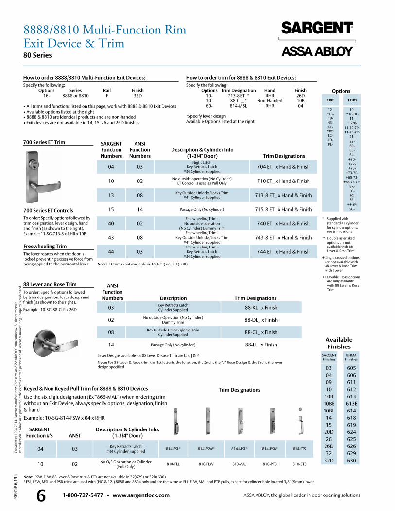
Trim Designations
SARGENT Function Numbers
ANSIFunction Numbers
ANSIFunction Numbers
Description & Cylinder Info (1-3/4" Door)
Freewheeling TrimThe lever rotates when the door is locked preventing excessive force from being applied to the horizontal lever
Keyed & Non Keyed Pull Trim for 8888 & 8810 Devices
Use the six digit designation (Ex “866-MAL”) when ordering trim without an Exit Device, always specify options, designation, finish & hand
Example: 10-SG-814-FSW x 04 x RHR
SARGENT Function #’s ANSI
Description & Cylinder Info. (1-3/4" Door)
Available Finishes
SARGENT Finishes
BHMA Finishes
03 04 09 10
10B 10BE 10BL
1415
20D26
26D32
32D
605 606 611 612 613
613E614618619624625626629 630
700 Series ET Trim
04 03Night Latch
Key Retracts Latch#34 Cylinder Supplied
704 ET_ x Hand & Finish
10 02 No outside operation (No Cylinder)ET Control is used as Pull Only 710 ET_ x Hand & Finish
13 08 Key Outside Unlocks/Locks Trim #41 Cylinder Supplied 713-8 ET_ x Hand & Finish
15 14 Passage Only (No cylinder) 715-8 ET_ x Hand & Finish
40 02Freewheeling Trim -
No outside operation (No Cylinder) Dummy Trim
740 ET_ x Hand & Finish
43 08Freewheeling Trim -
Key Outside Unlocks/Locks Trim #41 Cylinder Supplied
743-8 ET_ x Hand & Finish
44 03Freewheeling Trim - Key Retracts Latch
#34 Cylinder Supplied744 ET_ x Hand & Finish
03 Key Retracts Latch Cylinder Supplied 88-KL_ x Finish
02 No outside Operation (No Cylinder)Dummy Trim 88-DL_ x Finish
08 Key Outside Unlocks/locks TrimCylinder Supplied 88-CL_ x Finish
14 Passage Only (No cylinder) 88-LL_ x Finish
04 03 Key Retracts Latch#34 Cylinder Supplied 814-FSL* 814-FSW* 814-MSL* 814-PSB* 814-STS
10 02 No O/S Operation or Cylinder (Pull Only) 810-FLL 810-FLW 810-MAL 810-PTB 810-STS
Note: ET trim is not available in 32 (629) or 32D (630)
Lever Designs available for 88 Lever & Rose Trim are L, B, J & P
Note: For 88 Lever & Rose trim, the 1st letter is the function, the 2nd is the “L” Rose Design & the 3rd is the lever design specified
Note: FSW, FLW, 88 Lever & Rose trim & ET’s are not available in 32(629) or 32D(630) * FSL, FSW, MSL and PSB trims are used with (HC-& 12-) 8888 and 8804 only and are the same as FLL, FLW, MAL and PTB pulls, except for cylinder hole located 3/8” (9mm) lower .
Options
Exit Trim
12-*16-19-43-GL-
CPC-LC-LD-PL-
10-**10-UL-
11-11-70-
11-72-7P-11-73-7P-
21-22-60-63-64-
+70-+72-+73-
+73-7P-+65-73-
+65-73-7P-BR-LC-SC-SE-
++ SF-SG-
Trim Designations
How to order 8888/8810 Multi-Function Exit Devices:Specify the following: Options Series Rail Finish 16- 8888 or 8810 F 32D
• All trims and functions listed on this page, work with 8888 & 8810 Exit Devices• Available options listed at the right• 8888 & 8810 are identical products and are non-handed• Exit devices are not available in 14, 15, 26 and 26D finishes
How to order trim for 8888 & 8810 Exit Devices:Specify the following: Options Trim Designation Hand Finish 10- 713-8 ET_* RHR 26D 10- 88-CL_ * Non-Handed 10B 60- 814-MSL RHR 04
*Specify lever designAvailable Options listed at the right
* Supplied with standard 41 cylinder, for cylinder options, see trim options
** Double asterisked options are not available with 88 Lever & Rose Trim
+ Single crossed options are not available with 88 Lever & Rose Trim with J Lever
++ Double Cross options are only available with 88 Lever & Rose Trim
88 Lever and Rose TrimTo order: Specify options followed by trim designation, lever design and finish (as shown to the right) .
Example: 10-SG-88-CLP x 26D
Description Trim Designations
700 Series ET ControlsTo order: Specify options followed by trim designation, lever design, hand and finish (as shown to the right) . Example: 11-SG-713-8 x RHR x 10B
8888/8810 Multi-Function RimExit Device & Trim
1-800-727-5477 • www.sargentlock.com 7
80 Series
9064
1:P
6/1/
14
Copy
right
© 1
998-
2014
, Sar
gent
Man
ufac
turin
g Co
mpa
ny, a
n AS
SA A
BLO
Y G
roup
com
pany
. All
right
s res
erve
d.
Re
prod
uctio
n in
who
le o
r in
part
with
out t
he e
xpre
ss w
ritte
n pe
rmis
sion
of S
arge
nt M
anuf
actu
ring
Com
pany
is p
rohi
bite
d.
649 Strike • Supplied standard for panic &
fire rated openings • Surface applied • Black nylon coated
688 Trim Retrofit Kit
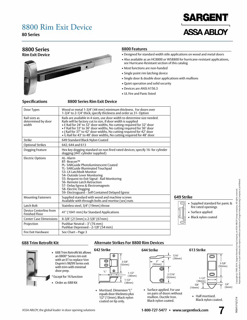
Specifications 8800 Series Rim Exit Device
8800 Features• Designed for standard width stile applications on wood and metal doors• Also available as an HC8800 or WS8800 for hurricane-resistant applications,
see Hurricane-Resistant section of this catalog• Most functions are non-handed• Single point rim latching device• Single door & double door applications with mullions• Quiet operation and solid security• Devices are ANSI A156 .3• UL Fire and Panic listed
8800 Series Rim Exit Device
Door Types Wood or metal 1-3/4" (44 mm) minimum thickness . For doors over 1-3/4" to 2-1/4" thick, specify thickness and order as 31- Option
Rail sizes as Rails are available in 4 sizes, use door width to determine size needed . determined by door Rails will be factory cut to size, if door width is supplied width • E Rail for 24" to 32" door widths, No cutting required for 32" door • F Rail for 33" to 36" door widths, No cutting required for 36" door • J Rail for 37" to 42" door widths, No cutting required for 42" door • G Rail for 43" to 48" door widths, No cutting required for 48" door Strike 649 Standard Black Nylon Coated Optional Strikes 642, 644 and 613 Dogging Feature Hex key dogging standard on non fired rated devices; specify 16- for cylinder dogging (#41 cylinder supplied) Electric Options AL- Alarm BT- Beacon™ PL- SARGuide Photoluminescent Coated TL- SARGuide Illuminated Touchpad 53- LX Latchbolt Monitor 54- Outside Lever Monitoring 55- Request-to-Exit Signal - Rail Monitoring 56- Remote Latch Retraction 57- Delay Egress & Electromagnets 58- Electric Dogging 59- Electroguard – Self Contained Delayed Egress Mounting Fasteners Supplied standard with wood and machine screws
Available with through-bolts and mortise (sex) nuts Latch Bolt Stainless steel, 3/4" (19mm) throw Device Centerline from 41" (1041 mm) for Standard Applications Finished Floor Center Case Dimensions 8-3/8" (213mm) x 2-5/8" (67mm) Projection Pushbar Neutral – 3" (76 mm)
Pushbar Depressed – 2-1/8" (54 mm) Fire Exit Hardware See Chart – Page 3
• Mortised . Dimension “L” equals door thickness plus 1/2" (13mm) . Black nylon coated on lip only .
Alternate Strikes For 8800 Rim Devices
• Half mortised . Black nylon coated .
• Surface applied . For use on pairs of doors without mullion . Ductile Iron . Black nylon coated .
1/4" (6mm)
1-1/2" (38mm)
5/8" (16mm)
3-5/8" (92mm)
1-1/2"(38mm)
3-5/8" (92mm)
1-1/2" (38mm)
“L”
7/16" (38mm)
2” (92mm)
2-7/16"(62mm)
613 Strike642 Strike 644 Strike• 688 Trim Retrofit kit allows
an 8800* Series rim exit with an ET to replace Von Duprin’s 98/99 Series exit with trim with minimal door prep .
* Except for 16 function
• Order as: 688 Kit
8800 Rim Exit Device
1-800-727-5477 • www.sargentlock.com8
80 Series
9064
1:P
6/1/
14
Copy
right
© 1
998-
2014
, Sar
gent
Man
ufac
turin
g Co
mpa
ny, a
n AS
SA A
BLO
Y G
roup
com
pany
. All
right
s res
erve
d.
Re
prod
uctio
n in
who
le o
r in
part
with
out t
he e
xpre
ss w
ritte
n pe
rmis
sion
of S
arge
nt M
anuf
actu
ring
Com
pany
is p
rohi
bite
d.
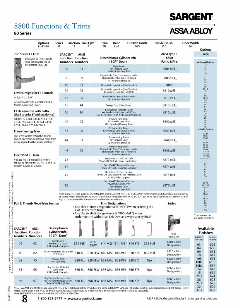
8800 Panic & Fire
Options Series Function Rail Lgth Trim Hand Outside Finish Inside Finish Door Width F1-83-56 88 13 F ETL RHR 26D 32D 36"
04 03Night Latch
Key Retracts Latch#34 Cylinder Supplied
8804 x ET_
06 09Key unlocks Trim, Trim retracts latch/
Trim relocks when key is removed#41 Cylinder Supplied
8806 x ET_
10 01 No outside operation (No Cylinder) 8810
10 02 No outside operation (No Cylinder)ET Control is used as Pull Only 8810 x ET_
13 08 Key Outside Unlocks/locks Trim #41 Cylinder Supplied 8813 x ET_
15 14 Passage Only (No cylinder) 8815 x ET_
16 10Key Outside Retracts Latch;
Key Inside Unlocks/Locks O/S TrimO/S #34 Cylinder & I/S #44 Cylinder Supplied
8816 x ET_
40 02Freewheeling Trim -
No outside operation (No Cylinder) Dummy Trim
8840 x ET_
43 08Freewheeling Trim -
Key Outside Unlocks/locks Trim #41 Cylinder Supplied
8843 x ET_
44 03Freewheeling Trim - Key Retracts Latch
#34 Cylinder Supplied8844 x ET_
46 09Freewheeling Trim -
Key unlocks Trim, Trim retracts latch/ Trim relocks when key is removed
#41 Cylinder Supplied8846 x ET_
73 Electrified ET Trim - Fail Safe Power Off, Unlocks Lever (No Cylinder) 8873 x ET_
74 Electrified ET Trim - Fail Secure Power Off, Locks Lever (No Cylinder) 8874 x ET_
75Electrified ET Trim - Fail Safe
Power Off, Unlocks Lever, Key Retracts Latch #34 Cylinder Supplied
8875 x ET_
76Electrified ET Trim - Fail Secure
Power Off, Locks Lever, Key Retracts Latch
#34 Cylinder Supplied8876 x ET_
ANSI Type 1 Options
Description & Cylinder Info (1-3/4" Door)
8800Panic & Fire
8800
Mechanical Options: 12- 16- 19- 31- 36- 37- 43- 53- 54- 55- 56-
56-HK- 57- 58- 59-
BC-59- 76-85-86-87- AL- BT-
CPC- GL- LD- PL- SG- TB- TL-
Cylinder Options: 10-
10-21- 10UL- 10-63-
11- 11-21- 11-60- 11-63- 11-64-
11-70-7P- 11-72-7P- 11-73-7P-
11-65-73-7P- 21- 22- 51- 52- 60- 63- 64- 70- 72- 73-
65-73- 65-73-7P-
73-7P- 81- 82-
F1-82- 83-
F1-83- 84- BR- LC-
*SC- *SE-
Lever Designs for ET ControlsA, B, E, F, J, L, P, W
Also available with Coastal Series & Studio Collection Levers
ET Designation with Suffix (Used to order ET without device)8800 Series: 704, 706-8, 710, 713-8, 715-8, 716, 740, 743-8, 744, 746-8, 773-8, 774-8, 775-8 & 776-8
Freewheeling TrimThe lever rotates when the door is locked preventing excessive force from being applied to the horizontal lever
Note: Exit devices are available in all standard finishes, except 14, 15, 26 & 26D . With these finishes, exit devices are supplied in 32 or 32D to match accordingly . 26 or 26D is automatically supplied when 32 or 32D is specified . For nickel finishes, specify 14/32 or 15/32D to receive nickel finished trims and stainless exit devices .
* FSL, FSW, MSL and PSB trims are used with (HC-& 12-) 8888 and 8804 only and are the same as FLL, FLW, MAL and PTB pulls except for cylinder hole located 3/8” (9mm) lower .Note: Thumb piece trims for 63 and 66 function devices are identical and are identified as 66 function when trim is ordered separately .Note: FLW & FSW trims are not available in 32(629) or 32D(630)
* Options are not available with 8816
Description & Cylinder Info.(1-3/4" Door)
04 03Night Latch
Key Retracts Latch #34 Cylinder Supplied
814-FSL* 814-FSW* 814-MSL* 814-PSB* 814-STS 8804 x Trim
Designation
Available Finishes
10 02 No O/S Operation or Cylinder (Pull Only) 810-FLL 810-FLW 810-MAL 810-PTB 810-STS 8810 x Trim
Designation
SARGENT Finishes
BHMA Finishes
28 15 Passage Only (No cylinder) 828-FLL 828-FLW 828-MAL 828-PTB 828-STS 8828 x Trim
Designation
03 04 09 10
10B 10BE10BL
1415
20D26
26D32
32D
605 606 611 612 613
613E614618619624625626629630
63 05Key Outside Unlocks/
Locks Trim #34 Cylinder Supplied
866-FLL 866-FLW 866-MAL 866-PTB 866-STS 8863 x TrimDesignation
66 07Key Outside Retracts Latch;
Key Inside Unlocks/Locks O/S Trim O/S #34 & I/S #44
866-FLL 866-FLW 866-MAL 866-PTB 866-STS
N/A
N/A
N/A
862 Pull
862 Pull
8866 x TrimDesignation
700 Series ET Trim Exits with ET Trim, specify
lever design after the ET designation (e .g ., ETL)
SeriesTrim Designations• Use three letter designations (Ex “PTB”) when ordering the
Exit Device with trim• Use the six digit designation (Ex “866-MAL”) when
ordering trim without an Exit Device, always specify finish
Pull & Thumb Piece Trim Section
SARGENT Function Numbers
ANSIFunction Numbers
SARGENT Function Numbers
ANSIFunction Numbers
Electrified ET TrimVoltage must be specified for the following functions: 73, 74, 75 and 76 . Specify: 12VDC or 24VDC
8800 Functions & Trims
1-800-727-5477 • www.sargentlock.com 9
80 Series
9064
1:P
6/1/
14
Copy
right
© 1
998-
2014
, Sar
gent
Man
ufac
turin
g Co
mpa
ny, a
n AS
SA A
BLO
Y G
roup
com
pany
. All
right
s res
erve
d.
Re
prod
uctio
n in
who
le o
r in
part
with
out t
he e
xpre
ss w
ritte
n pe
rmis
sion
of S
arge
nt M
anuf
actu
ring
Com
pany
is p
rohi
bite
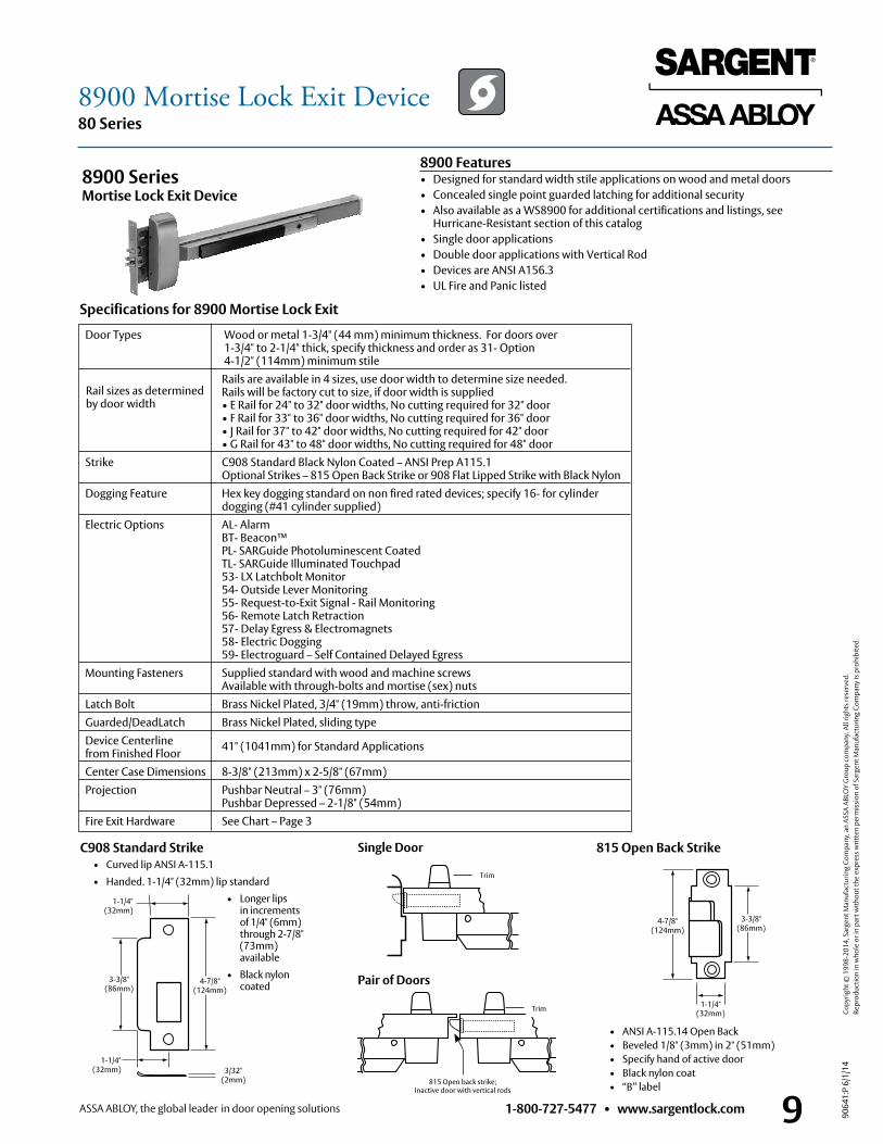
d.C908 Standard Strike • Curved lip ANSI A-115 .1
• Handed . 1-1/4" (32mm) lip standard
• Longer lips in increments of 1/4" (6mm) through 2-7/8" (73mm) available
• Black nylon coated
815 Open Back Strike
• ANSI A-115 .14 Open Back • Beveled 1/8" (3mm) in 2" (51mm) • Specify hand of active door • Black nylon coat • “B” label
4-7/8" (124mm)
3-3/8" (86mm)
1-1/4" (32mm)
Door Types Wood or metal 1-3/4" (44 mm) minimum thickness . For doors over 1-3/4" to 2-1/4" thick, specify thickness and order as 31- Option 4-1/2" (114mm) minimum stile
Rails are available in 4 sizes, use door width to determine size needed . Rails will be factory cut to size, if door width is supplied • E Rail for 24" to 32" door widths, No cutting required for 32" door • F Rail for 33" to 36" door widths, No cutting required for 36" door • J Rail for 37" to 42" door widths, No cutting required for 42" door • G Rail for 43" to 48" door widths, No cutting required for 48" door Strike C908 Standard Black Nylon Coated – ANSI Prep A115 .1
Optional Strikes – 815 Open Back Strike or 908 Flat Lipped Strike with Black Nylon Dogging Feature Hex key dogging standard on non fired rated devices; specify 16- for cylinder dogging (#41 cylinder supplied) Electric Options AL- Alarm BT- Beacon™ PL- SARGuide Photoluminescent Coated TL- SARGuide Illuminated Touchpad 53- LX Latchbolt Monitor 54- Outside Lever Monitoring 55- Request-to-Exit Signal - Rail Monitoring 56- Remote Latch Retraction 57- Delay Egress & Electromagnets 58- Electric Dogging 59- Electroguard – Self Contained Delayed Egress Mounting Fasteners Supplied standard with wood and machine screws
Available with through-bolts and mortise (sex) nuts Latch Bolt Brass Nickel Plated, 3/4" (19mm) throw, anti-friction Guarded/DeadLatch Brass Nickel Plated, sliding type Device Centerline 41" (1041mm) for Standard Applications from Finished Floor Center Case Dimensions 8-3/8" (213mm) x 2-5/8" (67mm) Projection Pushbar Neutral – 3" (76mm)
Pushbar Depressed – 2-1/8" (54mm) Fire Exit Hardware See Chart – Page 3
8900 Series Mortise Lock Exit Device
Trim
Single Door
Trim
Pair of Doors
Specifications for 8900 Mortise Lock Exit
1-1/4" (32mm)
1-1/4" (32mm) 3/32"
(2mm) 815 Open back strike;Inactive door with vertical rods
3-3/8" (86mm)
4-7/8" (124mm)
8900 Features• Designed for standard width stile applications on wood and metal doors• Concealed single point guarded latching for additional security• Also available as a WS8900 for additional certifications and listings, see
Hurricane-Resistant section of this catalog• Single door applications• Double door applications with Vertical Rod • Devices are ANSI A156 .3• UL Fire and Panic listed
Rail sizes as determined by door width
8900 Mortise Lock Exit Device
1-800-727-5477 • www.sargentlock.com10
80 Series
9064
1:P
6/1/
14
Copy
right
© 1
998-
2014
, Sar
gent
Man
ufac
turin
g Co
mpa
ny, a
n AS
SA A
BLO
Y G
roup
com
pany
. All
right
s res
erve
d.
Re
prod
uctio
n in
who
le o
r in
part
with
out t
he e
xpre
ss w
ritte
n pe
rmis
sion
of S
arge
nt M
anuf
actu
ring
Com
pany
is p
rohi
bite
d.
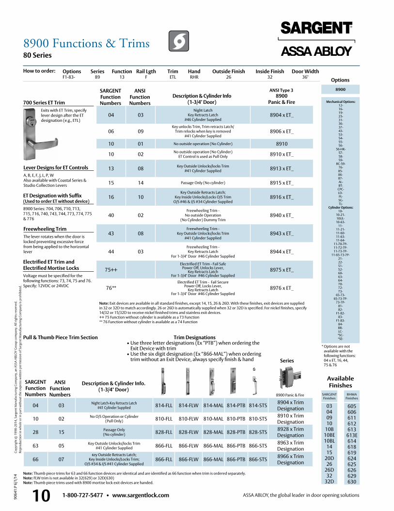
ANSI Type 3
Options
Description & Cylinder Info (1-3/4" Door)
8900 Panic & Fire
8900
Mechanical Options: 12- 16- 19- 23- 31- 36- 37- 43- 53- 54- 55- 56-
56-HK- 57- 58- 59-
BC-59- 76-85-86-87- AL- BT-
CPC- LD- PL- SG- TL-
Cylinder Options: 10-
10-21- 10UL- 10-63-
11- 11-21- 11-60- 11-63- 11-64-
11-70-7P- 11-72-7P- 11-73-7P-
11-65-73-7P- 21- 22- 51- 52- 60- 63- 64- 70- 72- 73-
65-73- 65-73-7P-
73-7P- 81- 82-
F1-82- 83-
F1-83- 84- BR- LC-
*SC- *SE-
Lever Designs for ET ControlsA, B, E, F, J, L, P, WAlso available with Coastal Series &Studio Collection Levers
Note: Exit devices are available in all standard finishes, except 14, 15, 26 & 26D . With these finishes, exit devices are supplied in 32 or 32D to match accordingly . 26 or 26D is automatically supplied when 32 or 32D is specified . For nickel finishes, specify 14/32 or 15/32D to receive nickel finished trims and stainless exit devices .++ 75 Function without cylinder is available as a 73 Function** 76 Function without cylinder is available as a 74 Function
Description & Cylinder Info. (1-3/4" Door)
Available Finishes
SARGENT Finishes
BHMA Finishes
03 04 09 10
10B10BE10BL
1415
20D26
26D32
32D
605 606 611 612 613
613E614618619624625626629 630
700 Series ET Trim Exits with ET Trim, specify
lever design after the ET designation (e .g ., ETL)
Options Series Function Rail Lgth Trim Hand Outside Finish Inside Finish Door Width F1-83- 89 13 F ETL RHR 26 32 36"
04 03Night Latch
Key Retracts Latch #46 Cylinder Supplied
8904 x ET_
06 09Key unlocks Trim, Trim retracts Latch/
Trim relocks when key is removed#41 Cylinder Supplied
8906 x ET_
10 01 No outside operation (No Cylinder) 8910
10 02 No outside operation (No Cylinder) ET Control is used as Pull Only 8910 x ET_
13 08 Key Outside Unlocks/locks Trim #41 Cylinder Supplied 8913 x ET_
15 14 Passage Only (No cylinder) 8915 x ET_
16 10Key Outside Retracts Latch;
Key Inside Unlocks/Locks O/S Trim O/S #46 & I/S #34 Cylinder Supplied
8916 x ET_
40 02Freewheeling Trim -
No outside Operation (No Cylinder) Dummy Trim
8940 x ET_
43 08Freewheeling Trim -
Key Outside Unlocks/locks Trim #41 Cylinder Supplied
8943 x ET_
44 03Freewheeling Trim - Key Retracts Latch
For 1-3/4" Door #46 Cylinder Supplied8944 x ET_
75++Electrified ET Trim - Fail Safe
Power Off, Unlocks Lever, Key Retracts Latch
For 1-3/4" Door #46 Cylinder Supplied8975 x ET_
76**Electrified ET Trim - Fail Secure
Power Off, Locks Lever, Key Retracts Latch
For 1-3/4" Door #46 Cylinder Supplied8976 x ET_
04 03 Night Latch-Key Retracts Latch#41 Cylinder Supplied 814-FLL 814-FLW 814-MAL 814-PTB 814-STS 8904 x Trim
Designation
10 02 No O/S Operation or Cylinder (Pull Only) 810-FLL 810-FLW 810-MAL 810-PTB 810-STS 8910 x Trim
Designation
28 15 Passage Only(No cylinder) 828-FLL 828-FLW 828-MAL 828-PTB 828-STS 8928 x Trim
Designation
63 05 Key Outside Unlocks/locks Trim #41 Cylinder Supplied 866-FLL 866-FLW 866-MAL 866-PTB 866-STS 8963 x Trim
Designation
66 07Key Outside Retracts Latch;
Key Inside Unlocks/Locks Trim; O/S #34 & I/S #41 Cylinder Supplied
866-FLL 866-FLW 866-MAL 866-PTB 866-STS 8966 x TrimDesignation
8900 Panic & Fire
Pull & Thumb Piece Trim Section
SARGENT Function Numbers
ANSIFunction Numbers
SARGENT Function Numbers
ANSIFunction Numbers
Series
How to order:
Freewheeling TrimThe lever rotates when the door is locked preventing excessive force from being applied to the horizontal lever
Electrified ET Trim and Electrified Mortise Locks Voltage must be specified for the following functions: 73, 74, 75 and 76 . Specify: 12VDC or 24VDC
ET Designation with Suffix (Used to order ET without device)8900 Series: 704, 706, 710, 713, 715, 716, 740, 743, 744, 773, 774, 775 & 776
* Options are not available with the following functions: 04 x ET, 16, 44, 75 & 76
Trim Designations• Use three letter designations (Ex “PTB”) when ordering the
Exit Device with trim• Use the six digit designation (Ex “866-MAL”) when ordering
trim without an Exit Device, always specify finish & hand
Note: Thumb piece trims for 63 and 66 function devices are identical and are identified as 66 function when trim is ordered separately .Note: FLW trim is not available in 32(629) or 32D(630)Note: Thumb piece trims used with 8900 mortise lock exit devices are handed .
8900 Functions & Trims
1-800-727-5477 • www.sargentlock.com 11
80 Series
9064
1:P
6/1/
14
Copy
right
© 1
998-
2014
, Sar
gent
Man
ufac
turin
g Co
mpa
ny, a
n AS
SA A
BLO
Y G
roup
com
pany
. All
right
s res
erve
d.
Re
prod
uctio
n in
who
le o
r in
part
with
out t
he e
xpre
ss w
ritte
n pe
rmis
sion
of S
arge
nt M
anuf
actu
ring
Com
pany
is p
rohi
bite
d.
648 & 653 Strikes (Alternate Strikes for 8700 SVR Devices)
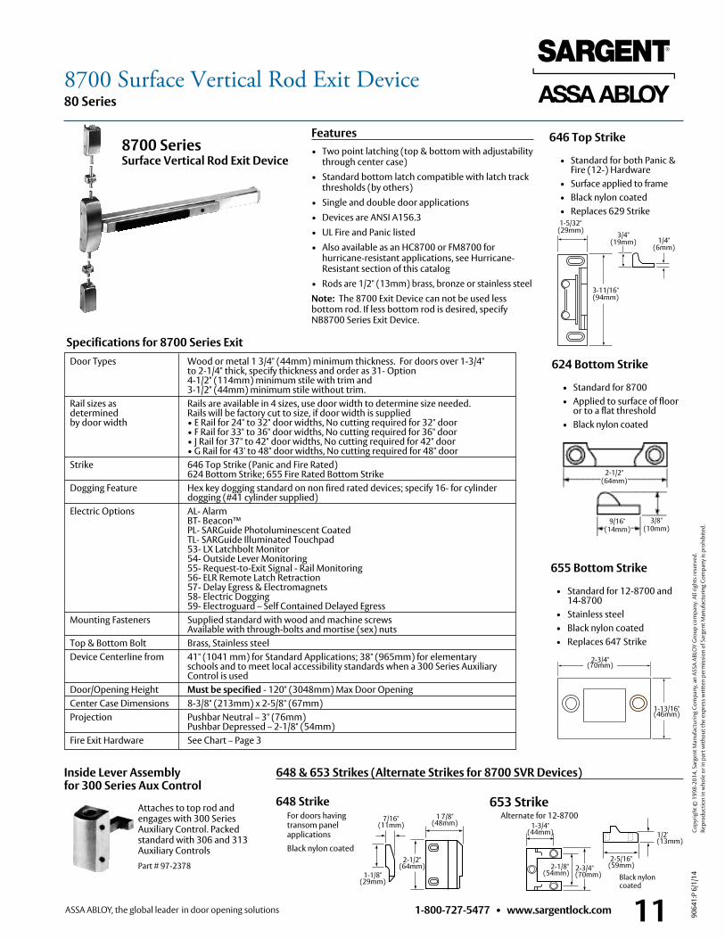
8700 Series Surface Vertical Rod Exit Device
624 Bottom Strike
• Standard for 8700 • Applied to surface of floor
or to a flat threshold • Black nylon coated
2-1/2" (64mm)
3/8" (10mm)
9/16" (14mm)
Specifications for 8700 Series Exit
Features• Two point latching (top & bottom with adjustability
through center case)• Standard bottom latch compatible with latch track
thresholds (by others)• Single and double door applications• Devices are ANSI A156 .3• UL Fire and Panic listed• Also available as an HC8700 or FM8700 for
hurricane-resistant applications, see Hurricane-Resistant section of this catalog
• Rods are 1/2" (13mm) brass, bronze or stainless steelNote: The 8700 Exit Device can not be used less bottom rod . If less bottom rod is desired, specify NB8700 Series Exit Device .
646 Top Strike
• Standard for both Panic & Fire (12-) Hardware
• Surface applied to frame • Black nylon coated • Replaces 629 Strike
1-5/32"(29mm)
3-11/16"(94mm)
3/4" (19mm) 1/4"
(6mm)
655 Bottom Strike
• Standard for 12-8700 and 14-8700
• Stainless steel • Black nylon coated • Replaces 647 Strike
2-3/4" (70mm)
1-13/16"(46mm)
Inside Lever Assembly for 300 Series Aux Control
Attaches to top rod and engages with 300 Series Auxiliary Control . Packed standard with 306 and 313 Auxiliary ControlsPart # 97-2378
1 7/8" (48mm)
1-1/8" (29mm)
7/16" (11mm)
2-1/2" (64mm)
648 StrikeFor doors having transom panel applications
Black nylon coated
Alternate for 12-87001-3/4"
(44mm)
2-3/4" (70mm)
2-1/8" (54mm)
653 Strike
1/2' (13mm)
2-5/16" (59mm)
Black nylon coated
Door Types Wood or metal 1 3/4" (44mm) minimum thickness . For doors over 1-3/4" to 2-1/4" thick, specify thickness and order as 31- Option 4-1/2" (114mm) minimum stile with trim and 3-1/2" (44mm) minimum stile without trim .
Rail sizes as Rails are available in 4 sizes, use door width to determine size needed . determined Rails will be factory cut to size, if door width is supplied by door width • E Rail for 24" to 32" door widths, No cutting required for 32" door • F Rail for 33" to 36" door widths, No cutting required for 36" door • J Rail for 37" to 42" door widths, No cutting required for 42" door • G Rail for 43' to 48" door widths, No cutting required for 48" door Strike 646 Top Strike (Panic and Fire Rated)
624 Bottom Strike; 655 Fire Rated Bottom Strike Dogging Feature Hex key dogging standard on non fired rated devices; specify 16- for cylinder dogging (#41 cylinder supplied) Electric Options AL- Alarm BT- Beacon™ PL- SARGuide Photoluminescent Coated TL- SARGuide Illuminated Touchpad 53- LX Latchbolt Monitor 54- Outside Lever Monitoring 55- Request-to-Exit Signal - Rail Monitoring 56- ELR Remote Latch Retraction 57- Delay Egress & Electromagnets 58- Electric Dogging 59- Electroguard – Self Contained Delayed Egress Mounting Fasteners Supplied standard with wood and machine screws
Available with through-bolts and mortise (sex) nuts Top & Bottom Bolt Brass, Stainless steel Device Centerline from 41" (1041 mm) for Standard Applications; 38" (965mm) for elementary
schools and to meet local accessibility standards when a 300 Series Auxiliary Control is used
Door/Opening Height Must be specified - 120" (3048mm) Max Door Opening Center Case Dimensions 8-3/8" (213mm) x 2-5/8" (67mm) Projection Pushbar Neutral – 3" (76mm)
Pushbar Depressed – 2-1/8" (54mm) Fire Exit Hardware See Chart – Page 3
8700 Surface Vertical Rod Exit Device
1-800-727-5477 • www.sargentlock.com12
80 Series
9064
1:P
6/1/
14
Copy
right
© 1
998-
2014
, Sar
gent
Man
ufac
turin
g Co
mpa
ny, a
n AS
SA A
BLO
Y G
roup
com
pany
. All
right
s res
erve
d.
Re
prod
uctio
n in
who
le o
r in
part
with
out t
he e
xpre
ss w
ritte
n pe
rmis
sion
of S
arge
nt M
anuf
actu
ring
Com
pany
is p
rohi
bite
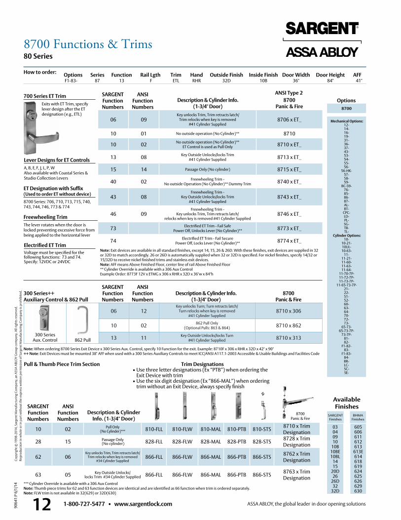
d. Description & Cylinder Info. (1-3/4" Door)
8700 Panic & Fire
8700Panic & Fire
ANSI Type 2 OptionsDescription & Cylinder Info.
(1-3/4" Door)8700
Panic & Fire 8700
Mechanical Options: 12- 14- 16- 19- 31- 36- 37- 43- 53- 54- 55- 56-
56-HK- 57- 58- 59-
BC-59- 76-85-86-87- AL- BT-
CPC- LD- PL- SG- TB- TL-
Cylinder Options: 10-
10-21- 10UL- 10-63-
11- 11-21- 11-60- 11-63- 11-64-
11-70-7P- 11-72-7P- 11-73-7P-
11-65-73-7P- 21- 22- 51- 52- 60- 63- 64- 70- 72- 73-
65-73- 65-73-7P-
73-7P- 81- 82-
F1-82- 83-
F1-83- 84- BR- LC- SC- SE-
Freewheeling TrimThe lever rotates when the door is locked preventing excessive force from being applied to the horizontal lever
Electrified ET TrimVoltage must be specified for the following functions: 73 and 74 . Specify: 12VDC or 24VDC
Description & Cylinder Info. (1-3/4" Door)
Available Finishes
SARGENT Finishes
BHMA Finishes
03 04 09 10
10B 10BE10BL
1415
20D26
26D32
32D
605 606 611 612 613
613E614618619624625626629 630
700 Series ET Trim Exits with ET Trim, specify
lever design after the ET designation (e .g ., ETL)
Options Series Function Rail Lgth Trim Hand Outside Finish Inside Finish Door Width Door Height AFF F1-83- 87 13 F ETL RHR 32D 10B 36" 84" 41"
06 09 Key unlocks Trim, Trim retracts latch/
Trim relocks when key is removed #41 Cylinder Supplied
8706 x ET_
10 01 No outside operation (No Cylinder)** 8710
10 02 No outside operation (No Cylinder)** ET Control is used as Pull Only 8710 x ET_
13 08 Key Outside Unlocks/locks Trim #41 Cylinder Supplied 8713 x ET_
15 14 Passage Only (No cylinder) 8715 x ET_
40 02 Freewheeling Trim - No outside Operation (No Cylinder)** Dummy Trim 8740 x ET_
43 08Freewheeling Trim -
Key Outside Unlocks/locks Trim#41 Cylinder Supplied
8743 x ET_
46 09Freewheeling Trim -
Key unlocks Trim, Trim retracts latch/relocks when key is removed #41 Cylinder Supplied
8746 x ET_
73 Electrified ET Trim - Fail SafePower Off, Unlocks Lever (No Cylinder)** 8773 x ET_
74 Electrified ET Trim - Fail SecurePower Off, Locks Lever (No Cylinder)** 8774 x ET_
10 02 Pull Only(No Cylinder)*** 810-FLL 810-FLW 810-MAL 810-PTB 810-STS 8710 x Trim
Designation
28 15 Passage Only (No cylinder) 828-FLL 828-FLW 828-MAL 828-PTB 828-STS 8728 x Trim
Designation
62 06Key unlocks Trim, Trim retracts latch/
Trim relocks when key is removed #34 Cylinder Supplied
866-FLL 866-FLW 866-MAL 866-PTB 866-STS 8762 x TrimDesignation
63 05 Key Outside Unlocks/ locks Trim #34 Cylinder Supplied 866-FLL 866-FLW 866-MAL 866-PTB 866-STS 8763 x Trim
Designation
06 12Key unlocks Turn; Turn retracts latch/
Turn relocks when key is removed#41 Cylinder Supplied
8710 x 306
10 02 862 Pull Only(Optional Pulls: 863 & 864) 8710 x 862
13 11 Key Outside Unlocks/locks Turn#41 Cylinder Supplied 8710 x 313862 Pull
SARGENT Function Numbers
ANSIFunction Numbers
SARGENT Function Numbers
300 Series++ Auxiliary Control & 862 Pull
ANSIFunction Numbers
SARGENT Function Numbers
ANSIFunction Numbers
300 Series Aux . Control
How to order:
Note: Exit devices are available in all standard finishes, except 14, 15, 26 & 26D . With these finishes, exit devices are supplied in 32 or 32D to match accordingly . 26 or 26D is automatically supplied when 32 or 32D is specified . For nickel finishes, specify 14/32 or 15/32D to receive nickel finished trims and stainless exit devices . Note: AFF means Above Finished Floor, center line of rail Above Finished Floor** Cylinder Override is available with a 306 Aux ControlExample Order: 8773F 12V x ETMG x 306 x RHR x 32D x 36"w x 84"h
*** Cylinder Override is available with a 306 Aux ControlNote: Thumb piece trims for 62 and 63 function devices are identical and are identified as 66 function when trim is ordered separately .Note: FLW trim is not available in 32(629) or 32D(630)
Pull & Thumb Piece Trim Section
ET Designation with Suffix (Used to order ET without device)8700 Series: 706, 710, 713, 715, 740, 743, 744, 746, 773 & 774
Lever Designs for ET ControlsA, B, E, F, J, L, P, WAlso available with Coastal Series &Studio Collection Levers
Note: When ordering 8700 Series Exit Device x 300 Series Aux . Control, specify 10 Function for the exit . Example: 8710F x 306 x RHR x 32D x 42" x 90" ++ Note: Exit Devices must be mounted 38" AFF when used with a 300 Series Auxiliary Controls to meet ICC/ANSI A117 .1-2003 Accessible & Usable Buildings and Facilities Code
Trim Designations• Use three letter designations (Ex “PTB”) when ordering the
Exit Device with trim• Use the six digit designation (Ex “866-MAL”) when ordering
trim without an Exit Device, always specify finish
8700 Functions & Trims
1-800-727-5477 • www.sargentlock.com 13
80 Series
9064
1:P
6/1/
14
Copy
right
© 1
998-
2014
, Sar
gent
Man
ufac
turin
g Co
mpa
ny, a
n AS
SA A
BLO
Y G
roup
com
pany
. All
right
s res
erve
d.
Re
prod
uctio
n in
who
le o
r in
part
with
out t
he e
xpre
ss w
ritte
n pe
rmis
sion
of S
arge
nt M
anuf
actu
ring
Com
pany
is p
rohi
bite
d.
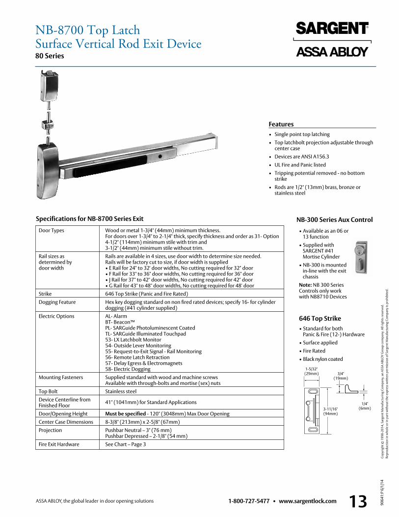
Features• Single point top latching• Top latchbolt projection adjustable through
center case• Devices are ANSI A156 .3• UL Fire and Panic listed• Tripping potential removed - no bottom
strike• Rods are 1/2" (13mm) brass, bronze or
stainless steel
Door Types Wood or metal 1-3/4" (44mm) minimum thickness . For doors over 1-3/4" to 2-1/4" thick, specify thickness and order as 31- Option 4-1/2" (114mm) minimum stile with trim and 3-1/2" (44mm) minimum stile without trim .
Rail sizes as Rails are available in 4 sizes, use door width to determine size needed . determined by Rails will be factory cut to size, if door width is supplied door width • E Rail for 24" to 32' door widths, No cutting required for 32" door
• F Rail for 33" to 36" door widths, No cutting required for 36" door • J Rail for 37" to 42" door widths, No cutting required for 42" door • G Rail for 43" to 48" door widths, No cutting required for 48' door
Strike 646 Top Strike (Panic and Fire Rated) Dogging Feature Hex key dogging standard on non fired rated devices; specify 16- for cylinder dogging (#41 cylinder supplied) Electric Options AL- Alarm BT- Beacon™ PL- SARGuide Photoluminescent Coated TL- SARGuide Illuminated Touchpad 53- LX Latchbolt Monitor 54- Outside Lever Monitoring 55- Request-to-Exit Signal - Rail Monitoring 56- Remote Latch Retraction 57- Delay Egress & Electromagnets 58- Electric Dogging Mounting Fasteners Supplied standard with wood and machine screws
Available with through-bolts and mortise (sex) nuts Top Bolt Stainless steel Device Centerline from 41" (1041mm) for Standard Applications Finished Floor Door/Opening Height Must be specified - 120" (3048mm) Max Door Opening Center Case Dimensions 8-3/8" (213mm) x 2-5/8" (67mm) Projection Pushbar Neutral – 3" (76 mm)
Pushbar Depressed – 2-1/8" (54 mm) Fire Exit Hardware See Chart – Page 3
Specifications for NB-8700 Series Exit
646 Top Strike• Standard for both
Panic & Fire (12-) Hardware• Surface applied• Fire Rated• Black nylon coated
3/4" (19mm)
1/4" (6mm)
1-5/32"(29mm)
3-11/16"(94mm)
NB-300 Series Aux Control
• Available as an 06 or 13 function
• Supplied with SARGENT #41 Mortise Cylinder
• NB-300 is mounted in-line with the exit chassis
Note: NB 300 Series Controls only work with NB8710 Devices
NB-8700 Top LatchSurface Vertical Rod Exit Device
1-800-727-5477 • www.sargentlock.com14
80 Series
9064
1:P
6/1/
14
Copy
right
© 1
998-
2014
, Sar
gent
Man
ufac
turin
g Co
mpa
ny, a
n AS
SA A
BLO
Y G
roup
com
pany
. All
right
s res
erve
d.
Re
prod
uctio
n in
who
le o
r in
part
with
out t
he e
xpre
ss w
ritte
n pe
rmis
sion
of S
arge
nt M
anuf
actu
ring
Com
pany
is p
rohi
bite
d.
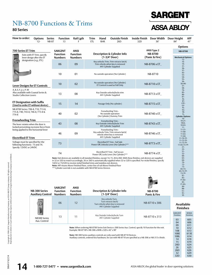
ANSI Type 2 Options
Description & Cylinder Info(1-3/4" Door)
NB-8700 (Panic & Fire)
NB-8700
Mechanical Options:12- 16- 19- 31- 36- 37- 43- 53- 54- 55- 56-
56-HK- 57- 58- 76-85-86-87- AL- BT-
CPC- LD- PL- SG- TB- TL-
Cylinder Options: 10-
10-21- 10UL- 10-63-
11- 11-21- 11-60- 11-63- 11-64-
11-70-7P- 11-72-7P- 11-73-7P-
11-65-73-7P- 21- 22- 51- 52- 60- 63- 64- 70- 72- 73-
65-73- 65-73-7P-
73-7P- 81- 82-
F1-82- 83-
F1-83- 84- BR- LC-SC-SE-
Lever Designs for ET ControlsA, B, E, F, J, L, P, WAlso available with Coastal Series & Studio Collection Levers
Freewheeling TrimThe lever rotates when the door is locked preventing excessive force from being applied to the horizontal lever
Available Finishes
SARGENT Finishes
BHMA Finishes
03 04 09 10
10B 10BE10BL
1415
20D26
26D32
32D
605 606 611 612 613
613E614618619624625626629 630
700 Series ET Trim Exits with ET Trim, specify
lever design after the ET designation (e .g ., ETL)
Options Series Function Rail Lgth Trim Hand Outside Finish Inside Finish Door Width Door Height AFF 12- NB-87 13 F ETL RHR 26D 32D 36" 84" 41"
06 09 Key unlocks Trim, Trim retracts latch/
Trim relocks when key is removed #41 Cylinder Supplied
NB-8706 x ET_
10 01 No outside operation (No Cylinder) NB-8710
10 02 No outside operation (No Cylinder) ET Control is used as Pull Only NB-8710 x ET_
13 08 Key Outside unlocks/locks trim #41 Cylinder Supplied NB-8713 x ET_
15 14 Passage Only (No cylinder) NB-8715 x ET_
40 02Freewheeling Trim -
No outside operation (No Cylinder) Dummy Trim
NB-8740 x ET_
43 08Freewheeling Trim -
Key Outside Unlocks/locks Trim#41 Cylinder Supplied
NB-8743 x ET_
46 09Freewheeling Trim -
Key unlocks Trim, Trim retracts latch/relocks when key is removed
#41 Cylinder Supplied
NB-8746 x ET_
73 Electrified ET Trim - Fail SafePower Off, Unlocks Lever (No Cylinder)*** NB-8773 x ET_
74 Electrified ET Trim - Fail SecurePower Off, Locks Lever (No Cylinder)*** NB-8774 x ET_
Note: When ordering NB-8700 Series Exit Device x 300 Series Aux . Control, specify 10 Function for the exit . Example: NB-8710F x NB-306 x RHR x 32D x 42" x 90"
Note: NB-300 Series auxiliary controls are only used with NB-8710 Devices .Auxiliary controls, ordered less hardware, for use with NB-8710 are specified as a NB-306 or NB-313 x finish .
NB-8700Panic & Fire
SARGENT Function Numbers
ANSIFunction Numbers
How to order:
06 12Key unlocks Turn,
Turn retracts latch/ Turn relocks when key is removed
#41 Cylinder Supplied
NB-8710 x 306
13 11 Key Outside Unlocks/locks Turn#41 Cylinder Supplied NB-8710 x 313
SARGENT Function Numbers
NB-300 Series Auxiliary Control
ANSIFunction Numbers
NB300 Series Aux . Control
Note: Exit devices are available in all standard finishes, except 14, 15, 26 & 26D . With these finishes, exit devices are supplied in 32 or 32D to match accordingly . 26 or 26D is automatically supplied when 32 or 32D is specified . For nickel finishes, specify 14/32 or 15/32D to receive nickel finished trims and stainless exit devices .Note: AFF means Above Finished Floor, center line of rail Above Finished Floor*** Cylinder override is not available with NB-8700 Series Devices
Electrified ET TrimVoltage must be specified for the following functions: 73 and 74 . Specify: 12VDC or 24VDC
Description & Cylinder Info(1-3/4" Door)
ET Designation with Suffix (Used to order ET without device)NB-8700 Series: 706-8, 710, 713-8, 715-8, 740, 743-8, 746-8, 773-8 & 774-8
NB-8700 Functions & Trims
1-800-727-5477 • www.sargentlock.com 15
80 Series
9064
1:P
6/1/
14
Copy
right
© 1
998-
2014
, Sar
gent
Man
ufac
turin
g Co
mpa
ny, a
n AS
SA A
BLO
Y G
roup
com
pany
. All
right
s res
erve
d.
Re
prod
uctio
n in
who
le o
r in
part
with
out t
he e
xpre
ss w
ritte
n pe
rmis
sion
of S
arge
nt M
anuf
actu
ring
Com
pany
is p
rohi
bite
d.
606 Bottom Strike
• Furnished with expansion shields • Mortised into floor • Stainless steel
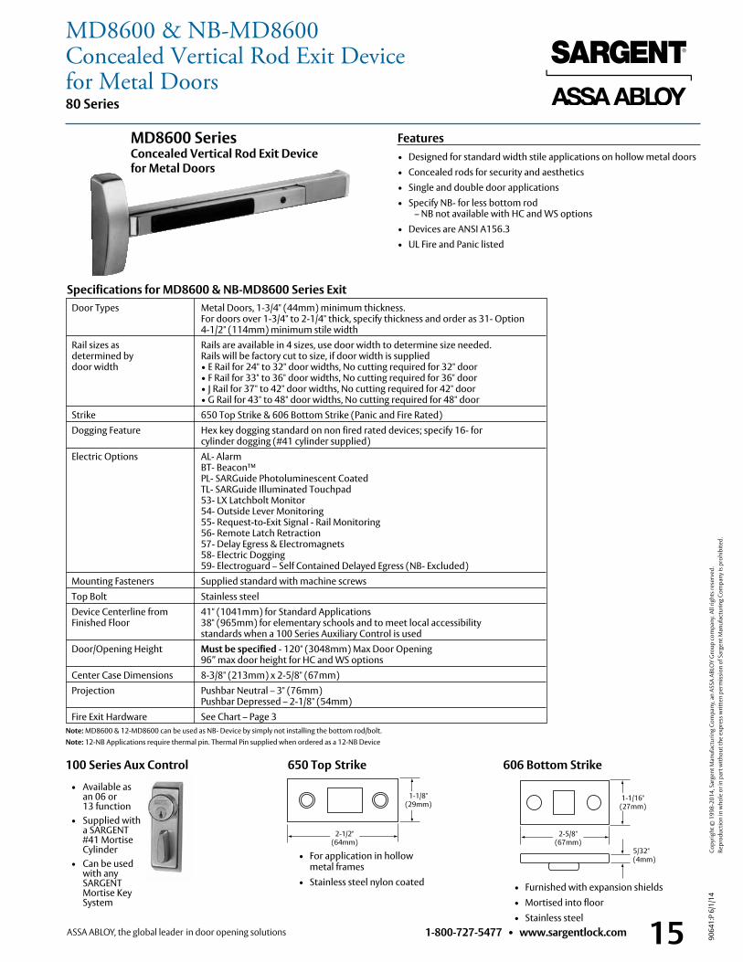
Door Types Metal Doors, 1-3/4" (44mm) minimum thickness . For doors over 1-3/4" to 2-1/4" thick, specify thickness and order as 31- Option 4-1/2" (114mm) minimum stile width
Rail sizes as Rails are available in 4 sizes, use door width to determine size needed . determined by Rails will be factory cut to size, if door width is supplied door width • E Rail for 24" to 32" door widths, No cutting required for 32" door • F Rail for 33" to 36" door widths, No cutting required for 36" door • J Rail for 37" to 42" door widths, No cutting required for 42" door • G Rail for 43" to 48" door widths, No cutting required for 48" door Strike 650 Top Strike & 606 Bottom Strike (Panic and Fire Rated) Dogging Feature Hex key dogging standard on non fired rated devices; specify 16- for cylinder dogging (#41 cylinder supplied) Electric Options AL- Alarm BT- Beacon™ PL- SARGuide Photoluminescent Coated TL- SARGuide Illuminated Touchpad 53- LX Latchbolt Monitor 54- Outside Lever Monitoring 55- Request-to-Exit Signal - Rail Monitoring 56- Remote Latch Retraction 57- Delay Egress & Electromagnets 58- Electric Dogging 59- Electroguard – Self Contained Delayed Egress (NB- Excluded) Mounting Fasteners Supplied standard with machine screws Top Bolt Stainless steel Device Centerline from 41" (1041mm) for Standard Applications Finished Floor 38" (965mm) for elementary schools and to meet local accessibility standards when a 100 Series Auxiliary Control is used Door/Opening Height Must be specified - 120" (3048mm) Max Door Opening
96” max door height for HC and WS options Center Case Dimensions 8-3/8" (213mm) x 2-5/8" (67mm) Projection Pushbar Neutral – 3" (76mm)
Pushbar Depressed – 2-1/8" (54mm) Fire Exit Hardware See Chart – Page 3
Specifications for MD8600 & NB-MD8600 Series Exit
Features• Designed for standard width stile applications on hollow metal doors• Concealed rods for security and aesthetics• Single and double door applications• Specify NB- for less bottom rod
– NB not available with HC and WS options • Devices are ANSI A156 .3• UL Fire and Panic listed
MD8600 Series Concealed Vertical Rod Exit Device for Metal Doors
650 Top Strike
• For application in hollow metal frames
• Stainless steel nylon coated
2-1/2" (64mm)
1-1/8"(29mm)
5/32" (4mm)
1-1/16" (27mm)
2-5/8" (67mm)
Note: MD8600 & 12-MD8600 can be used as NB- Device by simply not installing the bottom rod/bolt . Note: 12-NB Applications require thermal pin . Thermal Pin supplied when ordered as a 12-NB Device
100 Series Aux Control
• Available as an 06 or 13 function
• Supplied with a SARGENT #41 Mortise Cylinder
• Can be used with any SARGENT Mortise Key System
MD8600 & NB-MD8600Concealed Vertical Rod Exit Device for Metal Doors
1-800-727-5477 • www.sargentlock.com16
80 Series
9064
1:P
6/1/
14
Copy
right
© 1
998-
2014
, Sar
gent
Man
ufac
turin
g Co
mpa
ny, a
n AS
SA A
BLO
Y G
roup
com
pany
. All
right
s res
erve
d.
Re
prod
uctio
n in
who
le o
r in
part
with
out t
he e
xpre
ss w
ritte
n pe
rmis
sion
of S
arge
nt M
anuf
actu
ring
Com
pany
is p
rohi
bite
d.
ANSI Type 8
Options
Lever Designs for ET ControlsA, B, E, F, J, L, P, WAlso available with Coastal Series & Studio Collection Levers
Freewheeling TrimThe lever rotates when the door is locked preventing excessive force from being applied to the horizontal lever
Electrified ET TrimVoltage must be specified for the following functions: 73 and 74 . Specify: 12VDC or 24VDC
Note: Exit devices are available in all standard finishes, except 14, 15, 26 & 26D . With these finishes, exit devices are supplied in 32 or 32D to match accordingly . 26 or 26D is automatically supplied when 32 or 32D is specified . For nickel finishes, specify 14/32 or 15/32D to receive nickel finished trims and stainless exit devices .Note: AFF means Above Finished Floor, center line of rail Above Finished Floor** Cylinder Override is available with a 106 Aux ControlExample Order: MD8673F 12V x ETMG x 106 x RHR x 32D x 36"w x 84"h
Available Finishes
SARGENT Finishes
BHMA Finishes
03 04 09 10
10B 10BE10BL
1415
20D26
26D32
32D
605 606 611 612 613
613E614618619624625626629 630
700 Series ET Trim Exits with ET Trim, specify
lever design after the ET designation (e .g ., ETL)
Options Series Function Rail Lgth Trim Hand Outside Finish Inside Finish Door Width Door Height AFF57-NB- MD86 13 F ETL RHR 03 03 36" 84" 41"
06 09 Key unlocks Trim, Trim retracts latch/
Trim relocks when key is removed #41 Cylinder Supplied
MD8606 x ET_
10 01 No outside operation (No Cylinder)** MD8610
10 02 No outside operation (No Cylinder)** ET Control is used as Pull Only MD8610 x ET_
13 08 Key Outside Unlocks/locks Trim #41 Cylinder Supplied MD8613 x ET_
15 14 Passage Only (No cylinder) MD8615 x ET_
40 02Freewheeling Trim -
No outside Operation (No Cylinder)** Dummy Trim
MD8640 x ET_
43 08Freewheeling Trim -
Key Outside Unlocks/locks Trim #41 Cylinder Supplied
MD8643 x ET_
46 09
Freewheeling Trim - Key unlocks Trim, Trim retracts latch/
Trim relocks when key is removed #41 Cylinder Supplied
MD8646 x ET_
73 Electrified ET Trim - Fail Safe Power Off, Unlocks Lever (No Cylinder)** MD8673 x ET_
74 Electrified ET Trim - Fail Secure Power Off, Locks Lever (No Cylinder)** MD8674 x ET_
MD8600
Mechanical Options: 12- 16- 19- 31- 36- 37- 43- 53- 54- 55- 56-
56-HK- 57- 58- 59-
BC-59- 76-85-86-87- AL- BT-
CPC-HC- LD- NB- PL- SG- TL-
WS- Cylinder Options:
10- 10-21- 10UL- 10-63-
11- 11-21- 11-60- 11-63- 11-64-
11-70-7P- 11-72-7P- 11-73-7P-
11-65-73-7P- 21- 22- 51- 52- 60- 63- 64- 70- 72- 73-
65-73- 65-73-7P-
73-7P- 81- 82-
F1-82- 83-
F1-83- 84- BR- LC-SC-SE-
Note: When ordering MD8600/NB-MD8600 Series Exit Device x 100 Series Aux . Control, specify 10 Function for the exit . Example: MD8610F x 106 x RHR x 32D x 42" x 90"
++ Note: Exit Devices must be mounted 38" AFF when used with a 100 Series Auxiliary Controls to meet ICC/ANSI A117 .1-2003 Accessible & Usable Buildings and Facilities Code
MD8600Panic & Fire
Description & Cylinder Info(1-3/4" Door)
SARGENT Function Numbers
ANSIFunction Numbers
MD8600 Panic & Fire
How to order:
06 12Key unlocks Turn, Turn retracts latch/
Turn relocks when key is removed#41 Cylinder Supplied
MD8610 x 106
10 02 862 Pull Only(Optional Pulls: 863 & 864) MD8610 x 862 Pull
13 11 Key Outside Unlocks/locks Turn#41 Cylinder Supplied MD8610 x 113 862 Pull
SARGENT Function Numbers
Description & Cylinder Info(1-3/4" Door)
100 Series Auxiliary Control++& 862 Pull
ANSIFunction Numbers
100 Series Aux . Control
ET Designation with Suffix (Used to order ET without device)MD8600 & NB-MD8600 Series: 706-4, 710-4, 713-4, 715-4, 740-4, 743-4, 746-4, 773-4, & 774-4
MD8600 & NB-MD8600 Functions & Trims for Metal Doors
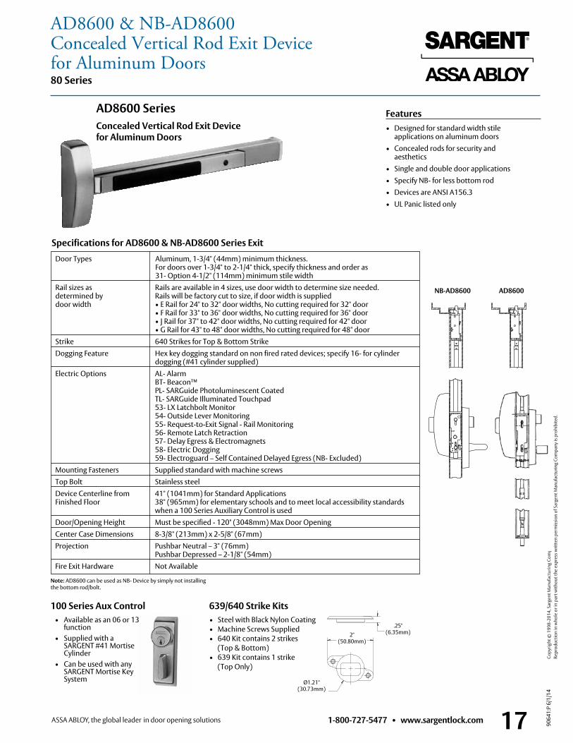
1-800-727-5477 • www.sargentlock.com 17
80 Series
9064
1:P
6/1/
14
Copy
right
© 1
998-
2014
, Sar
gent
Man
ufac
turin
g Co
mpa
ny, a
n AS
SA A
BLO
Y G
roup
com
pany
. All
right
s res
erve
d.
Re
prod
uctio
n in
who
le o
r in
part
with
out t
he e
xpre
ss w
ritte
n pe
rmis
sion
of S
arge
nt M
anuf
actu
ring
Com
pany
is p
rohi
bite
d.
• Steel with Black Nylon Coating• Machine Screws Supplied• 640 Kit contains 2 strikes
(Top & Bottom)• 639 Kit contains 1 strike
(Top Only)
639/640 Strike Kits
Door Types Aluminum, 1-3/4" (44mm) minimum thickness . For doors over 1-3/4" to 2-1/4" thick, specify thickness and order as 31- Option 4-1/2" (114mm) minimum stile width Rail sizes as Rails are available in 4 sizes, use door width to determine size needed . determined by Rails will be factory cut to size, if door width is supplied door width • E Rail for 24" to 32" door widths, No cutting required for 32" door • F Rail for 33" to 36" door widths, No cutting required for 36" door • J Rail for 37" to 42" door widths, No cutting required for 42" door • G Rail for 43" to 48" door widths, No cutting required for 48" door Strike 640 Strikes for Top & Bottom Strike Dogging Feature Hex key dogging standard on non fired rated devices; specify 16- for cylinder dogging (#41 cylinder supplied) Electric Options AL- Alarm BT- Beacon™ PL- SARGuide Photoluminescent Coated TL- SARGuide Illuminated Touchpad 53- LX Latchbolt Monitor 54- Outside Lever Monitoring 55- Request-to-Exit Signal - Rail Monitoring 56- Remote Latch Retraction 57- Delay Egress & Electromagnets 58- Electric Dogging 59- Electroguard – Self Contained Delayed Egress (NB- Excluded) Mounting Fasteners Supplied standard with machine screws Top Bolt Stainless steel Device Centerline from 41" (1041mm) for Standard Applications Finished Floor 38" (965mm) for elementary schools and to meet local accessibility standards when a 100 Series Auxiliary Control is used Door/Opening Height Must be specified - 120" (3048mm) Max Door Opening Center Case Dimensions 8-3/8" (213mm) x 2-5/8" (67mm) Projection Pushbar Neutral – 3" (76mm)
Pushbar Depressed – 2-1/8" (54mm) Fire Exit Hardware Not Available
Specifications for AD8600 & NB-AD8600 Series Exit
Features• Designed for standard width stile
applications on aluminum doors• Concealed rods for security and aesthetics• Single and double door applications• Specify NB- for less bottom rod • Devices are ANSI A156 .3• UL Panic listed only
AD8600 SeriesConcealed Vertical Rod Exit Device for Aluminum Doors
2.00in50.80mm
1.21in30.73mm
.25in6.35mm
2" (50 .80mm)
.25" (6 .35mm)
Ø1 .21" (30 .73mm)
Note: AD8600 can be used as NB- Device by simply not installing the bottom rod/bolt .
NB-MD8400MD84008400WD8600 NB-WD8600NB-MD8600MD8600 NB-MD8400MD8400
8400WD8600 NB-WD8600NB-MD8600MD8600
NB-MD8400MD84008400WD8600 NB-WD8600NB-MD8600MD8600
NB-AD8600 AD8600
100 Series Aux Control • Available as an 06 or 13
function • Supplied with a
SARGENT #41 Mortise Cylinder
• Can be used with any SARGENT Mortise Key System
AD8600 & NB-AD8600Concealed Vertical Rod Exit Devicefor Aluminum Doors
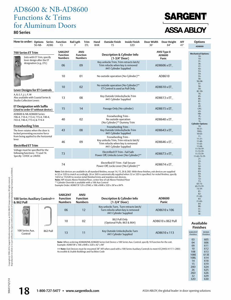
1-800-727-5477 • www.sargentlock.com18
80 Series
9064
1:P
6/1/
14
Copy
right
© 1
998-
2014
, Sar
gent
Man
ufac
turin
g Co
mpa
ny, a
n AS
SA A
BLO
Y G
roup
com
pany
. All
right
s res
erve
d.
Re
prod
uctio
n in
who
le o
r in
part
with
out t
he e
xpre
ss w
ritte
n pe
rmis
sion
of S
arge
nt M
anuf
actu
ring
Com
pany
is p
rohi
bite
d.
ANSI Type 8
Options
Lever Designs for ET ControlsA, B, E, F, J, L, P, WAlso available with Coastal Series & Studio Collection Levers
Freewheeling TrimThe lever rotates when the door is locked preventing excessive force from being applied to the horizontal lever
Electrified ET TrimVoltage must be specified for the following functions: 73 and 74 . Specify: 12VDC or 24VDC
Note: Exit devices are available in all standard finishes, except 14, 15, 26 & 26D . With these finishes, exit devices are supplied in 32 or 32D to match accordingly . 26 or 26D is automatically supplied when 32 or 32D is specified . For nickel finishes, specify 14/32 or 15/32D to receive nickel finished trims and stainless exit devices .Note: AFF means Above Finished Floor, center line of rail Above Finished Floor** Cylinder Override is available with a 106 Aux ControlExample Order: AD8673F 12V x ETMG x 106 x RHR x 32D x 36"w x 84"h
Available Finishes
SARGENT Finishes
BHMA Finishes
03 04 09 10
10B 10BE10BL
1415
20D26
26D32
32D
605 606 611 612 613
613E614618619624625626629 630
700 Series ET Trim Exits with ET Trim, specify
lever design after the ET designation (e .g ., ETL)
Options Series Function Rail Lgth Trim Hand Outside Finish Inside Finish Door Width Door Height AFF56-NB- AD86 13 F ETL RHR 15 32D 36" 84" 41"
06 09 Key unlocks Trim, Trim retracts latch/
Trim relocks when key is removed #41 Cylinder Supplied
AD8606 x ET_
10 01 No outside operation (No Cylinder)** AD8610
10 02 No outside operation (No Cylinder)** ET Control is used as Pull Only AD8610 x ET_
13 08 Key Outside Unlocks/locks Trim #41 Cylinder Supplied AD8613 x ET_
15 14 Passage Only (No cylinder) AD8615 x ET_
40 02Freewheeling Trim -
No outside operation (No Cylinder)** Dummy Trim
AD8640 x ET_
43 08Freewheeling Trim -
Key Outside Unlocks/locks Trim #41 Cylinder Supplied
AD8643 x ET_
46 09
Freewheeling Trim - Key unlocks Trim, Trim retracts latch/
Trim relocks when key is removed #41 Cylinder Supplied
AD8646 x ET_
73 Electrified ET Trim - Fail Safe Power Off, Unlocks Lever (No Cylinder)** AD8673 x ET_
74 Electrified ET Trim - Fail Secure Power Off, Locks Lever (No Cylinder)** AD8674 x ET_
AD8600
Mechanical Options: 16- 19- 31- 36- 37- 43- 53- 54- 55- 56-
56-HK- 57- 58- 59-
BC-59- 76-85-86-87- AL- BT-
CPC- LD- NB- PL- SG- TL-
Cylinder Options: 10-
10-21- 10UL- 10-63-
11- 11-21- 11-60- 11-63- 11-64-
11-70-7P- 11-72-7P- 11-73-7P-
11-65-73-7P- 21- 22- 51- 52- 60- 63- 64- 70- 72- 73-
65-73- 65-73-7P-
73-7P- 81- 82-
F1-82- 83-
F1-83- 84- BR- LC-SC-SE-
Note: When ordering AD8600/NB-AD8600 Series Exit Device x 100 Series Aux . Control, specify 10 Function for the exit . Example: AD8610F x 106 x RHR x 32D x 42" x 90"
++ Note: Exit Devices must be mounted 38” AFF when used with a 100 Series Auxiliary Controls to meet ICC/ANSI A117 .1-2003 Accessible & Usable Buildings and Facilities Code
AD8600Panic
Description & Cylinder Info(1-3/4" Door)
AD8600Panic
How to order:
06 12Key unlocks Turn, Turn retracts latch/
Turn relocks when key is removed#41 Cylinder Supplied
AD8610 x 106
10 02 862 Pull Only(Optional Pulls: 863 & 864) AD8610 x 862 Pull
13 11 Key Outside Unlocks/locks Turn#41 Cylinder Supplied AD8610 x 113862 Pull
SARGENT Function Numbers
Description & Cylinder Info(1-3/4" Door)
100 Series Auxiliary Control++& 862 Pull
ANSIFunction Numbers
100 Series Aux . Control
ET Designation with Suffix (Used to order ET without device)AD8600 & NB-AD8600 Series: 706-4, 710-4, 713-4, 715-4, 740-4, 743-4, 746-4, 773-4, & 774-4
AD8600 & NB-AD8600Functions & Trimsfor Aluminum Doors
SARGENT Function Numbers
ANSIFunction Numbers
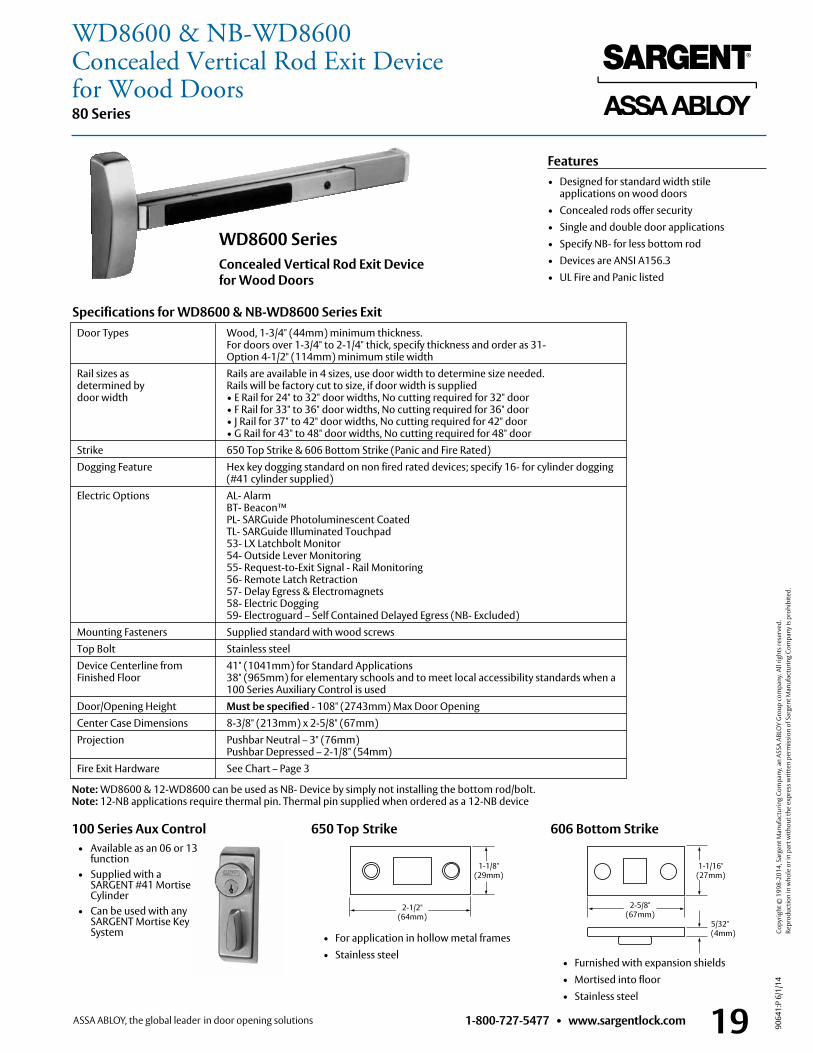
1-800-727-5477 • www.sargentlock.com 19
80 Series
9064
1:P
6/1/
14
Copy
right
© 1
998-
2014
, Sar
gent
Man
ufac
turin
g Co
mpa
ny, a
n AS
SA A
BLO
Y G
roup
com
pany
. All
right
s res
erve
d.
Re
prod
uctio
n in
who
le o
r in
part
with
out t
he e
xpre
ss w
ritte
n pe
rmis
sion
of S
arge
nt M
anuf
actu
ring
Com
pany
is p
rohi
bite
d.
606 Bottom Strike
• Furnished with expansion shields • Mortised into floor • Stainless steel
Door Types Wood, 1-3/4" (44mm) minimum thickness . For doors over 1-3/4" to 2-1/4" thick, specify thickness and order as 31- Option 4-1/2" (114mm) minimum stile width
Rail sizes as Rails are available in 4 sizes, use door width to determine size needed . determined by Rails will be factory cut to size, if door width is supplied door width • E Rail for 24" to 32" door widths, No cutting required for 32" door • F Rail for 33" to 36" door widths, No cutting required for 36" door • J Rail for 37" to 42" door widths, No cutting required for 42" door • G Rail for 43" to 48" door widths, No cutting required for 48" door Strike 650 Top Strike & 606 Bottom Strike (Panic and Fire Rated) Dogging Feature Hex key dogging standard on non fired rated devices; specify 16- for cylinder dogging (#41 cylinder supplied) Electric Options AL- Alarm BT- Beacon™ PL- SARGuide Photoluminescent Coated TL- SARGuide Illuminated Touchpad 53- LX Latchbolt Monitor 54- Outside Lever Monitoring 55- Request-to-Exit Signal - Rail Monitoring 56- Remote Latch Retraction 57- Delay Egress & Electromagnets 58- Electric Dogging 59- Electroguard – Self Contained Delayed Egress (NB- Excluded) Mounting Fasteners Supplied standard with wood screws Top Bolt Stainless steel Device Centerline from 41" (1041mm) for Standard Applications
Finished Floor 38" (965mm) for elementary schools and to meet local accessibility standards when a 100 Series Auxiliary Control is used
Door/Opening Height Must be specified - 108" (2743mm) Max Door Opening Center Case Dimensions 8-3/8" (213mm) x 2-5/8" (67mm) Projection Pushbar Neutral – 3" (76mm)
Pushbar Depressed – 2-1/8" (54mm) Fire Exit Hardware See Chart – Page 3
Specifications for WD8600 & NB-WD8600 Series Exit
Features• Designed for standard width stile applications on wood doors• Concealed rods offer security• Single and double door applications• Specify NB- for less bottom rod • Devices are ANSI A156 .3• UL Fire and Panic listed
650 Top Strike
• For application in hollow metal frames • Stainless steel
2-1/2" (64mm)
1-1/8"(29mm)
5/32" (4mm)
1-1/16" (27mm)
2-5/8" (67mm)
Note: WD8600 & 12-WD8600 can be used as NB- Device by simply not installing the bottom rod/bolt . Note: 12-NB applications require thermal pin . Thermal pin supplied when ordered as a 12-NB device
WD8600 SeriesConcealed Vertical Rod Exit Device for Wood Doors
100 Series Aux Control • Available as an 06 or 13
function • Supplied with a
SARGENT #41 Mortise Cylinder
• Can be used with any SARGENT Mortise Key System
WD8600 & NB-WD8600Concealed Vertical Rod Exit Devicefor Wood Doors
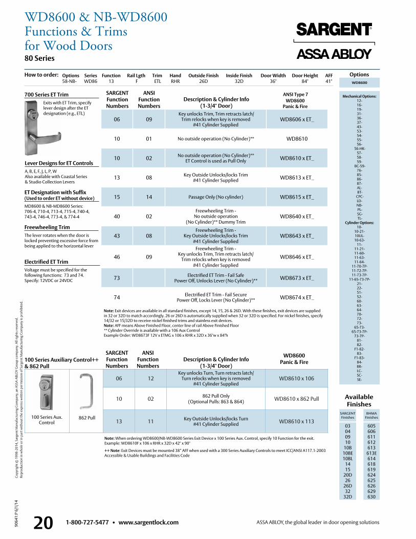
1-800-727-5477 • www.sargentlock.com20
80 Series
9064
1:P
6/1/
14
Copy
right
© 1
998-
2014
, Sar
gent
Man
ufac
turin
g Co
mpa
ny, a
n AS
SA A
BLO
Y G
roup
com
pany
. All
right
s res
erve
d.
Re
prod
uctio
n in
who
le o
r in
part
with
out t
he e
xpre
ss w
ritte
n pe
rmis
sion
of S
arge
nt M
anuf
actu
ring
Com
pany
is p
rohi
bite
d.
ANSI Type 7 WD8600 Panic & Fire
Lever Designs for ET ControlsA, B, E, F, J, L, P, WAlso available with Coastal Series & Studio Collection Levers
Freewheeling TrimThe lever rotates when the door is locked preventing excessive force from being applied to the horizontal lever
Electrified ET TrimVoltage must be specified for the following functions: 73 and 74 . Specify: 12VDC or 24VDC
Available Finishes
SARGENT Finishes
BHMA Finishes
03 04 09 10
10B 10BE10BL
1415
20D26
26D32
32D
605 606 611 612 613
613E614618619624625626629 630
700 Series ET Trim Exits with ET Trim, specify
lever design after the ET designation (e .g ., ETL)
Options Series Function Rail Lgth Trim Hand Outside Finish Inside Finish Door Width Door Height AFF58-NB- WD86 13 F ETL RHR 26D 32D 36" 84" 41"
06 09 Key unlocks Trim, Trim retracts latch/
Trim relocks when key is removed #41 Cylinder Supplied
WD8606 x ET_
10 01 No outside operation (No Cylinder)** WD8610
10 02 No outside operation (No Cylinder)** ET Control is used as Pull Only WD8610 x ET_
13 08 Key Outside Unlocks/locks Trim #41 Cylinder Supplied WD8613 x ET_
15 14 Passage Only (No cylinder) WD8615 x ET_
40 02Freewheeling Trim -
No outside operation (No Cylinder)** Dummy Trim
WD8640 x ET_
43 08Freewheeling Trim -
Key Outside Unlocks/locks Trim #41 Cylinder Supplied
WD8643 x ET_
46 09Freewheeling Trim -
Key unlocks Trim, Trim retracts latch/ Trim relocks when key is removed
#41 Cylinder Supplied
WD8646 x ET_
73 Electrified ET Trim - Fail Safe Power Off, Unlocks Lever (No Cylinder)** WD8673 x ET_
74 Electrified ET Trim - Fail Secure Power Off, Locks Lever (No Cylinder)** WD8674 x ET_
Note: When ordering WD8600/NB-WD8600 Series Exit Device x 100 Series Aux . Control, specify 10 Function for the exit . Example: WD8610F x 106 x RHR x 32D x 42" x 90"
++ Note: Exit Devices must be mounted 38” AFF when used with a 300 Series Auxiliary Controls to meet ICC/ANSI A117 .1-2003 Accessible & Usable Buildings and Facilities Code
OptionsWD8600
Mechanical Options: 12- 16- 19- 31- 36- 37- 43- 53- 54- 55- 56-
56-HK- 57- 58- 59-
BC-59- 76-85-86-87- AL- BT-
CPC- LD- NB- PL- SG- TL-
Cylinder Options: 10-
10-21- 10UL- 10-63-
11- 11-21- 11-60- 11-63- 11-64-
11-70-7P- 11-72-7P- 11-73-7P-
11-65-73-7P- 21- 22- 51- 52- 60- 63- 64- 70- 72- 73-
65-73- 65-73-7P-
73-7P- 81- 82-
F1-82- 83-
F1-83- 84- BR- LC-SC-SE-
Description & Cylinder Info(1-3/4" Door)
SARGENT Function Numbers
ANSIFunction Numbers
Note: Exit devices are available in all standard finishes, except 14, 15, 26 & 26D . With these finishes, exit devices are supplied in 32 or 32D to match accordingly . 26 or 26D is automatically supplied when 32 or 32D is specified . For nickel finishes, specify 14/32 or 15/32D to receive nickel finished trims and stainless exit devices .Note: AFF means Above Finished Floor, center line of rail Above Finished Floor** Cylinder Override is available with a 106 Aux ControlExample Order: WD8673F 12V x ETMG x 106 x RHR x 32D x 36"w x 84"h
How to order:
WD8600Panic & Fire
06 12Key unlocks Turn, Turn retracts latch/
Turn relocks when key is removed#41 Cylinder Supplied
WD8610 x 106
10 02 862 Pull Only(Optional Pulls: 863 & 864) WD8610 x 862 Pull
13 11 Key Outside Unlocks/locks Turn#41 Cylinder Supplied WD8610 x 113
862 Pull
SARGENT Function Numbers
Description & Cylinder Info(1-3/4" Door)
100 Series Auxiliary Control++& 862 Pull
ANSIFunction Numbers
100 Series Aux . Control
ET Designation with Suffix (Used to order ET without device)MD8600 & NB-MD8600 Series: 706-4, 710-4, 713-4, 715-4, 740-4, 743-4, 746-4, 773-4, & 774-4
WD8600 & NB-WD8600Functions & Trimsfor Wood Doors
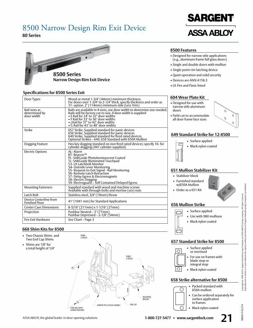
1-800-727-5477 • www.sargentlock.com 21
80 Series
9064
1:P
6/1/
14
Copy
right
© 1
998-
2014
, Sar
gent
Man
ufac
turin
g Co
mpa
ny, a
n AS
SA A
BLO
Y G
roup
com
pany
. All
right
s res
erve
d.
Re
prod
uctio
n in
who
le o
r in
part
with
out t
he e
xpre
ss w
ritte
n pe
rmis
sion
of S
arge
nt M
anuf
actu
ring
Com
pany
is p
rohi
bite
d.
8500 Features• Designed for narrow stile applications
(e .g ., aluminum frame full glass doors)• Single and double doors with mullion• Single point rim latching device• Quiet operation and solid security• Devices are ANSI A156 .3• UL Fire and Panic listed
Specifications for 8500 Series Exit
8500 Series Narrow Design Rim Exit Device
Door Types Wood or metal 1-3/4" (44mm) minimum thickness . For doors over 1-3/4" to 2-1/4" thick, specify thickness and order as 31- option . 2" (114mm) minimum stile (Less Trim)
Rail sizes as Rails are available in 4 sizes, use door width to determine size needed . determined by Rails will be factory cut to size, if door width is supplied door width • E Rail for 24" to 32" door widths • F Rail for 33" to 36" door widths • J Rail for 37" to 42" door widths • G Rail for 43" to 48" door widths Strike 657 Strike, Supplied standard for panic devices
656 Strike, Supplied standard for panic devices 649 Strike, Supplied standard for fired rated devices Optional Strikes – 649, 658 Standard with 650A Mullion
Dogging Feature Hex key dogging standard on non fired rated devices; specify 16- for cylinder dogging (#41 cylinder supplied) Electric Options AL- Alarm BT- Beacon™ PL- SARGuide Photoluminescent Coated TL- SARGuide Illuminated Touchpad 53- LX Latchbolt Monitor 54- Outside Lever Monitoring 55- Request-to-Exit Signal - Rail Monitoring 56- Remote Latch Retraction 57- Delay Egress & Electromagnets 58- Electric Dogging 59- Electroguard – Self Contained Delayed Egress Mounting Fasteners Supplied standard with wood and machine screws
Available with through-bolts and mortise (sex) nuts Latch Bolt Stainless steel, 3/4" (19mm) throw Device Centerline from 41" (1041 mm) for Standard Applications
Finished Floor Center Case Dimensions 8-5/16" (211mm) x 1-1/16" (27mm) Projection Pushbar Neutral – 3" (77mm)
Pushbar Depressed – 2-1/8" (54mm) Fire Exit Hardware See Chart – Page 3
657 Standard Strike for 8500 • Surface applied
or mortised • For use on frames with
blade stop or integral stop
• Black nylon coated
656 Mullion Strike • Surface applied • Use with 980 mullions • Black nylon coated
668 Shim Kits for 8500 • Two Chassis Shims and
Two End Cap Shims• Shims are 1/8" for
a total height of 1/4"
658 Strike alternative for 8500 • Packed standard with
650A mullion • Can be ordered separately for
surface application to frames
• Black nylon coated
SHIMS (2 REQ'D)
THRU-BOLT WITHSCREWS PROVIDED
NARROW STILE CHASSIS ASSEMBLY END CAP
MOUNTINGBRACKET
SHIMS (2 REQ'D)
649 Standard Strike for 12-8500 • Surface applied • Black nylon coated
8500 Narrow Design Rim Exit Device
651 Mullion Stabilizer Kit • Stabilizer block • Furnished standard
w/650A Mullion • Order as a 651 Kit
604 Wear Plate Kit• Designed for use with
narrow stile aluminum doors
• Field cut to accommodate all door frame face sizes
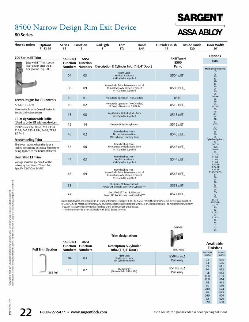
1-800-727-5477 • www.sargentlock.com22
80 Series
9064
1:P
6/1/
14
Copy
right
© 1
998-
2014
, Sar
gent
Man
ufac
turin
g Co
mpa
ny, a
n AS
SA A
BLO
Y G
roup
com
pany
. All
right
s res
erve
d.
Re
prod
uctio
n in
who
le o
r in
part
with
out t
he e
xpre
ss w
ritte
n pe
rmis
sion
of S
arge
nt M
anuf
actu
ring
Com
pany
is p
rohi
bite
d.
Options Series Function Rail Lgth Trim Hand Outside Finish Inside Finish Door Width F1-83-56 85 13 F ETL RHR 15 32D 36"
04 03Night Latch
Key Retracts Latch#34 Cylinder Supplied
8504 x ET_
06 09Key unlocks Trim, Trim retracts latch/
Trim relocks when key is removed#41 Cylinder Supplied
8506 x ET_
10 01 No outside operation (No Cylinder) 8510
10 02 No outside operation (No Cylinder) ET Control is used as Pull Only 8510 x ET_
13 08 Key Outside Unlocks/locks Trim #41 Cylinder Supplied 8513 x ET_
15 14 Passage Only (No cylinder) 8515 x ET_
40 02Freewheeling Trim -
No outside operation (No Cylinder) Dummy Trim
8540 x ET_
43 08Freewheeling Trim -
Key Outside Unlocks/locks Trim #41 Cylinder Supplied
8543 x ET_
44 03Freewheeling Trim - Key Retracts Latch
#34 Cylinder Supplied8544 x ET_
46 09Freewheeling Trim -
Key unlocks Trim, Trim retracts latch/ Trim relocks when key is removed
#41 Cylinder Supplied8546 x ET_
73 Electrified ET Trim - Fail Safe Power Off, Unlocks Lever (No Cylinder)*** 8573 x ET_
74 Electrified ET Trim - Fail Secure Power Off, Locks Lever (No Cylinder)*** 8574 x ET_
ANSI Type 4 Options
Description & Cylinder Info. (1-3/4" Door)8500 Panic
8500
Mechanical Options: 16-19- 31- 36- 37- 43- 53- 54- 55- 56-
56-HK- 57- 58- 59-
BC-59- 76-85-86-87- AL- BT-
CPC- GL- LD- PL- SG- TL-
Cylinder Options: 10-
10-21- 10UL- 10-63-
11- 11-21- 11-60- 11-63- 11-64-
11-70-7P- 11-72-7P- 11-73-7P-
11-65-73-7P- 21- 22- 51- 52- 60- 63- 64- 70- 72- 73-
65-73- 65-73-7P-
73-7P- 81- 82-
F1-82- 83-
F1-83- 84- BR- LC-SC-SE-
Lever Designs for ET ControlsA, B, E, F, J, L, P, W
Also available with Coastal Series &Studio Collection Levers
Freewheeling TrimThe lever rotates when the door is locked preventing excessive force from being applied to the horizontal lever
Note: Exit devices are available in all standard finishes, except 14, 15, 26 & 26D . With these finishes, exit devices are supplied in 32 or 32D to match accordingly . 26 or 26D is automatically supplied when 32 or 32D is specified . For nickel finishes, specify 14/32 or 15/32D to receive nickel finished trims and stainless exit devices .*** Cylinder override is not available with 8500 Series Devices
Available Finishes
SARGENT Finishes
BHMA Finishes
03 04 09 10
10B 10BE10BL
1415
20D26
26D32
32D
605 606 611 612 613
613E614618619624625626629 630
700 Series ET Trim Exits with ET Trim, specify
lever design after the ET designation (e .g ., ETL)
SARGENT Function Numbers
ANSIFunction Numbers
How to order:
Electrified ET TrimVoltage must be specified for the following functions: 73 and 74 . Specify: 12VDC or 24VDC
ET Designation with Suffix (Used to order ET without device)8500 Series: 704, 706-8, 710, 713-8, 715-8, 740, 743-8, 744, 746-8, 773-8 & 774-8
04 03Night Latch
Key Retracts Latch#34 Cylinder Supplied
8504 x 862Pull only
10 02 862 Pull Only(Optional Pulls: 863 & 864)
8510 x 862Pull only862 Pull
SARGENT Function Numbers
Description & Cylinder Info. (1-3/4" Door)Pull Trim Section
ANSIFunction Numbers 8500 Panic
Series
Trim designations
8500 Narrow Design Rim Exit Device
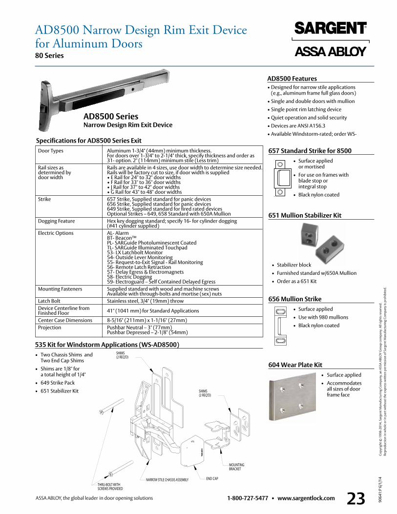
1-800-727-5477 • www.sargentlock.com 23
80 Series
9064
1:P
6/1/
14
Copy
right
© 1
998-
2014
, Sar
gent
Man
ufac
turin
g Co
mpa
ny, a
n AS
SA A
BLO
Y G
roup
com
pany
. All
right
s res
erve
d.
Re
prod
uctio
n in
who
le o
r in
part
with
out t
he e
xpre
ss w
ritte
n pe
rmis
sion
of S
arge
nt M
anuf
actu
ring
Com
pany
is p
rohi
bite
d.
AD8500 Features• Designed for narrow stile applications
(e .g ., aluminum frame full glass doors)• Single and double doors with mullion• Single point rim latching device• Quiet operation and solid security• Devices are ANSI A156 .3• Available Windstorm-rated; order WS-
Specifications for AD8500 Series Exit
AD8500 Series Narrow Design Rim Exit Device
Door Types Aluminum 1-3/4" (44mm) minimum thickness . For doors over 1-3/4" to 2-1/4" thick, specify thickness and order as 31- option . 2" (114mm) minimum stile (Less trim)
Rail sizes as Rails are available in 4 sizes, use door width to determine size needed . determined by Rails will be factory cut to size, if door width is supplied door width • E Rail for 24" to 32" door widths • F Rail for 33" to 36" door widths • J Rail for 37" to 42" door widths • G Rail for 43" to 48" door widths Strike 657 Strike, Supplied standard for panic devices 656 Strike, Supplied standard for panic devices 649 Strike, Supplied standard for fired rated devices Optional Strikes – 649, 658 Standard with 650A Mullion Dogging Feature Hex key dogging standard; specify 16- for cylinder dogging (#41 cylinder supplied) Electric Options AL- Alarm BT- Beacon™ PL- SARGuide Photoluminescent Coated TL- SARGuide Illuminated Touchpad 53- LX Latchbolt Monitor 54- Outside Lever Monitoring 55- Request-to-Exit Signal - Rail Monitoring 56- Remote Latch Retraction 57- Delay Egress & Electromagnets 58- Electric Dogging 59- Electroguard – Self Contained Delayed Egress Mounting Fasteners Supplied standard with wood and machine screws
Available with through-bolts and mortise (sex) nuts Latch Bolt Stainless steel, 3/4" (19mm) throw Device Centerline from 41" (1041 mm) for Standard Applications
Finished Floor Center Case Dimensions 8-5/16" (211mm) x 1-1/16" (27mm) Projection Pushbar Neutral – 3" (77mm)
Pushbar Depressed – 2-1/8" (54mm)
535 Kit for Windstorm Applications (WS-AD8500)• Two Chassis Shims and
Two End Cap Shims• Shims are 1/8" for
a total height of 1/4"• 649 Strike Pack• 651 Stabilizer Kit
SHIMS (2 REQ'D)
THRU-BOLT WITHSCREWS PROVIDED
NARROW STILE CHASSIS ASSEMBLY END CAP
MOUNTINGBRACKET
SHIMS (2 REQ'D)
651 Mullion Stabilizer Kit
• Stabilizer block • Furnished standard w/650A Mullion • Order as a 651 Kit
AD8500 Narrow Design Rim Exit Devicefor Aluminum Doors
657 Standard Strike for 8500 • Surface applied
or mortised • For use on frames with
blade stop or integral stop
• Black nylon coated
656 Mullion Strike • Surface applied • Use with 980 mullions • Black nylon coated
604 Wear Plate Kit • Surface applied • Accommodates
all sizes of door frame face

1-800-727-5477 • www.sargentlock.com24
80 Series
9064
1:P
6/1/
14
Copy
right
© 1
998-
2014
, Sar
gent
Man
ufac
turin
g Co
mpa
ny, a
n AS
SA A
BLO
Y G
roup
com
pany
. All
right
s res
erve
d.
Re
prod
uctio
n in
who
le o
r in
part
with
out t
he e
xpre
ss w
ritte
n pe
rmis
sion
of S
arge
nt M
anuf
actu
ring
Com
pany
is p
rohi
bite
d.
Options Series Function Rail Lgth Trim Hand Outside Finish Inside Finish Door Width F1-83-56 AD85 13 F ETL RHR 15 32D 36"
04 03Night Latch
Key Retracts Latch#34 Cylinder Supplied
AD8504 x ET_
06 09Key unlocks Trim, Trim retracts latch/
Trim relocks when key is removed#41 Cylinder Supplied
AD8506 x ET_
10 01 No outside operation (No Cylinder) AD8510
10 02 No outside operation (No Cylinder) ET Control is used as Pull Only AD8510 x ET_
13 08 Key Outside Unlocks/locks Trim #41 Cylinder Supplied AD8513 x ET_
15 14 Passage Only (No cylinder) AD8515 x ET_
40 02Freewheeling Trim -
No outside operation (No Cylinder) Dummy Trim
AD8540 x ET_
43 08Freewheeling Trim -
Key Outside Unlocks/locks Trim #41 Cylinder Supplied
AD8543 x ET_
44 03Freewheeling Trim - Key Retracts Latch
#34 Cylinder SuppliedAD8544 x ET_
46 09Freewheeling Trim -
Key unlocks Trim, Trim retracts latch/ Trim relocks when key is removed
#41 Cylinder SuppliedAD8546 x ET_
73 Electrified ET Trim - Fail Safe Power Off, Unlocks Lever (No Cylinder)*** AD8573 x ET_
74 Electrified ET Trim - Fail Secure Power Off, Locks Lever (No Cylinder)*** AD8574 x ET_
ANSI Type 4 Options
Description & Cylinder Info. (1-3/4" Door)AD8500
Panic
AD8500
Mechanical Options: 16-19- 31- 36- 37- 43- 53- 54- 55- 56-
56-HK- 57- 58- 59-
BC-59- 76-85-86-87- AL- BT-
CPC- GL- LD- PL- SG- TL- WS-
Cylinder Options: 10-
10-21- 10UL- 10-63-
11- 11-21- 11-60- 11-63- 11-64-
11-70-7P- 11-72-7P- 11-73-7P-
11-65-73-7P- 21- 22- 51- 52- 60- 63- 64- 70- 72- 73-
65-73- 65-73-7P-
73-7P- 81- 82-
F1-82- 83-
F1-83- 84- BR- LC-SC-SE-
Lever Designs for ET ControlsA, B, E, F, J, L, P, W
Also available with Coastal Series &Studio Collection Levers
Freewheeling TrimThe lever rotates when the door is locked preventing excessive force from being applied to the horizontal lever
Note: Exit devices are available in all standard finishes, except 14, 15, 26 & 26D . With these finishes, exit devices are supplied in 32 or 32D to match accordingly . 26 or 26D is automatically supplied when 32 or 32D is specified . For nickel finishes, specify 14/32 or 15/32D to receive nickel finished trims and stainless exit devices .*** Cylinder override is not available with AD8500 Series Devices
Available Finishes
SARGENT Finishes
BHMA Finishes
03 04 09 10
10B 10BE10BL
1415
20D26
26D32
32D
605 606 611 612 613
613E614618619624625626629 630
700 Series ET Trim Exits with ET Trim, specify
lever design after the ET designation (e .g ., ETL)
SARGENT Function Numbers
ANSIFunction Numbers
How to order:
Electrified ET TrimVoltage must be specified for the following functions: 73 and 74 . Specify: 12VDC or 24VDC
ET Designation with Suffix (Used to order ET without device)AD8500 Series: 704, 706-8, 710, 713-8, 715-8, 740, 743-8, 744, 746-8, 773-8 & 774-8
04 03Night Latch
Key Retracts Latch#34 Cylinder Supplied
AD8504 x 862Pull only
10 02 862 Pull Only(Optional Pulls: 863 & 864)
AD8510 x 862Pull only862 Pull
SARGENT Function Numbers
Description & Cylinder Info. (1-3/4" Door)Pull Trim Section
ANSIFunction Numbers AD8500 Panic
Series
Trim designations
AD8500 Narrow Design Rim Exit Device
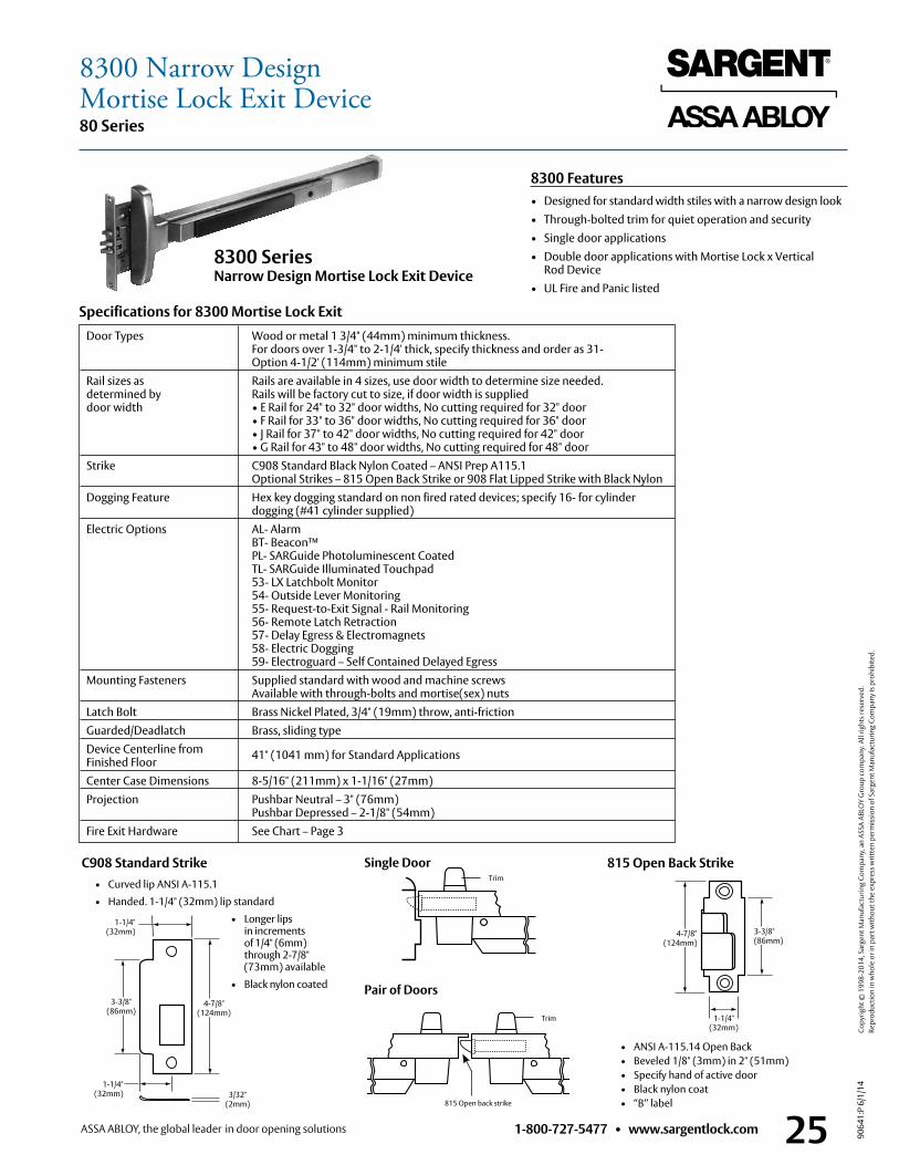
1-800-727-5477 • www.sargentlock.com 25
80 Series
9064
1:P
6/1/
14
Copy
right
© 1
998-
2014
, Sar
gent
Man
ufac
turin
g Co
mpa
ny, a
n AS
SA A
BLO
Y G
roup
com
pany
. All
right
s res
erve
d.
Re
prod
uctio
n in
who
le o
r in
part
with
out t
he e
xpre
ss w
ritte
n pe
rmis
sion
of S
arge
nt M
anuf
actu
ring
Com
pany
is p
rohi
bite
d.815 Open Back Strike
• ANSI A-115 .14 Open Back • Beveled 1/8" (3mm) in 2" (51mm) • Specify hand of active door • Black nylon coat • “B” label
4-7/8" (124mm)
3-3/8" (86mm)
1-1/4" (32mm)
Door Types Wood or metal 1 3/4" (44mm) minimum thickness . For doors over 1-3/4" to 2-1/4' thick, specify thickness and order as 31- Option 4-1/2' (114mm) minimum stile
Rail sizes as Rails are available in 4 sizes, use door width to determine size needed . determined by Rails will be factory cut to size, if door width is supplied door width • E Rail for 24" to 32" door widths, No cutting required for 32" door • F Rail for 33" to 36" door widths, No cutting required for 36" door • J Rail for 37" to 42" door widths, No cutting required for 42" door • G Rail for 43" to 48" door widths, No cutting required for 48" door Strike C908 Standard Black Nylon Coated – ANSI Prep A115 .1
Optional Strikes – 815 Open Back Strike or 908 Flat Lipped Strike with Black Nylon Dogging Feature Hex key dogging standard on non fired rated devices; specify 16- for cylinder dogging (#41 cylinder supplied) Electric Options AL- Alarm BT- Beacon™ PL- SARGuide Photoluminescent Coated TL- SARGuide Illuminated Touchpad 53- LX Latchbolt Monitor 54- Outside Lever Monitoring 55- Request-to-Exit Signal - Rail Monitoring 56- Remote Latch Retraction 57- Delay Egress & Electromagnets 58- Electric Dogging 59- Electroguard – Self Contained Delayed Egress Mounting Fasteners Supplied standard with wood and machine screws
Available with through-bolts and mortise(sex) nuts Latch Bolt Brass Nickel Plated, 3/4" (19mm) throw, anti-friction Guarded/Deadlatch Brass, sliding type Device Centerline from 41" (1041 mm) for Standard Applications
Finished Floor Center Case Dimensions 8-5/16" (211mm) x 1-1/16" (27mm) Projection Pushbar Neutral – 3" (76mm)
Pushbar Depressed – 2-1/8" (54mm) Fire Exit Hardware See Chart – Page 3
8300 Series Narrow Design Mortise Lock Exit Device
Trim
Single Door
Trim
Pair of Doors
Specifications for 8300 Mortise Lock Exit
815 Open back strike
C908 Standard Strike • Curved lip ANSI A-115 .1
• Handed . 1-1/4" (32mm) lip standard
• Longer lips in increments of 1/4" (6mm) through 2-7/8" (73mm) available
• Black nylon coated
1-1/4" (32mm)
1-1/4" (32mm) 3/32"
(2mm)
3-3/8" (86mm)
4-7/8" (124mm)
8300 Features• Designed for standard width stiles with a narrow design look• Through-bolted trim for quiet operation and security• Single door applications• Double door applications with Mortise Lock x Vertical
Rod Device• UL Fire and Panic listed
8300 Narrow DesignMortise Lock Exit Device
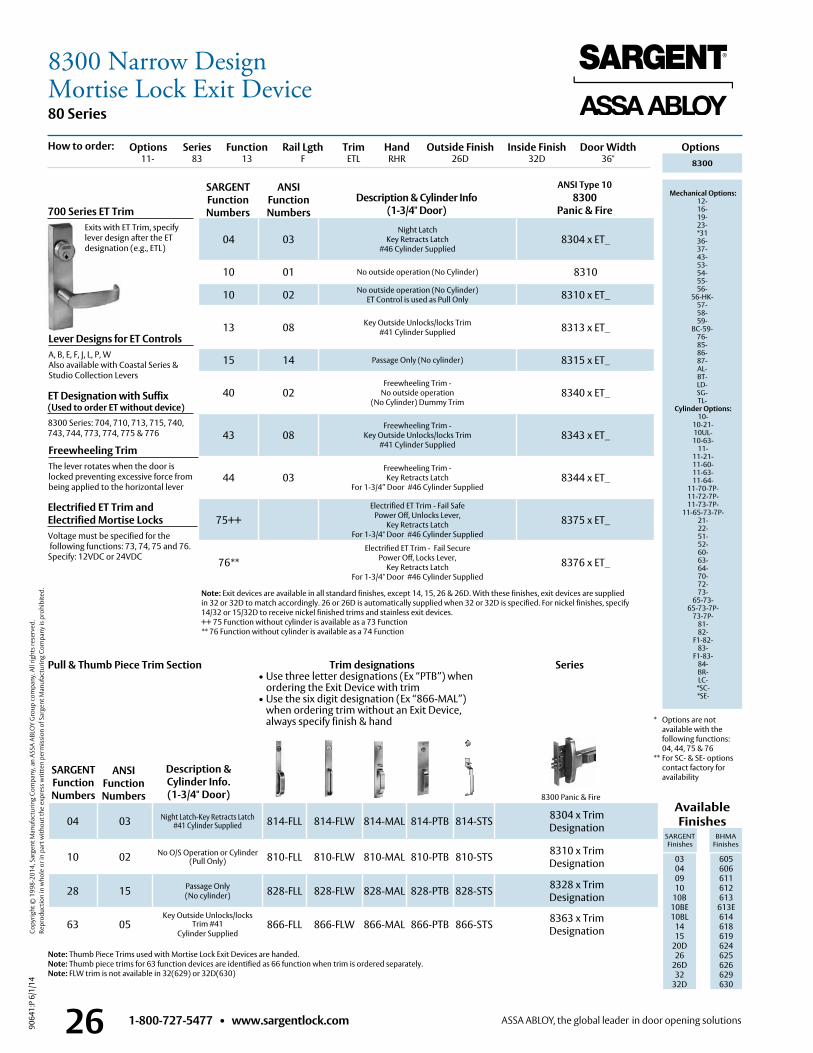
1-800-727-5477 • www.sargentlock.com26
80 Series
9064
1:P
6/1/
14
Copy
right
© 1
998-
2014
, Sar
gent
Man
ufac
turin
g Co
mpa
ny, a
n AS
SA A
BLO
Y G
roup
com
pany
. All
right
s res
erve
d.
Re
prod
uctio
n in
who
le o
r in
part
with
out t
he e
xpre
ss w
ritte
n pe
rmis
sion
of S
arge
nt M
anuf
actu
ring
Com
pany
is p
rohi
bite
d.
8300 Panic & Fire
ANSI Type 10Description & Cylinder Info
(1-3/4" Door)8300
Panic & Fire
Lever Designs for ET ControlsA, B, E, F, J, L, P, WAlso available with Coastal Series &Studio Collection Levers
Note: Exit devices are available in all standard finishes, except 14, 15, 26 & 26D . With these finishes, exit devices are supplied in 32 or 32D to match accordingly . 26 or 26D is automatically supplied when 32 or 32D is specified . For nickel finishes, specify 14/32 or 15/32D to receive nickel finished trims and stainless exit devices .++ 75 Function without cylinder is available as a 73 Function** 76 Function without cylinder is available as a 74 Function
Description & Cylinder Info. (1-3/4" Door)
700 Series ET Trim Exits with ET Trim, specify
lever design after the ET designation (e .g ., ETL)
04 03Night Latch
Key Retracts Latch #46 Cylinder Supplied
8304 x ET_
10 01 No outside operation (No Cylinder) 8310
10 02 No outside operation (No Cylinder) ET Control is used as Pull Only 8310 x ET_
13 08 Key Outside Unlocks/locks Trim #41 Cylinder Supplied 8313 x ET_
15 14 Passage Only (No cylinder) 8315 x ET_
40 02Freewheeling Trim -
No outside operation (No Cylinder) Dummy Trim
8340 x ET_
43 08Freewheeling Trim -
Key Outside Unlocks/locks Trim #41 Cylinder Supplied
8343 x ET_
44 03Freewheeling Trim - Key Retracts Latch
For 1-3/4” Door #46 Cylinder Supplied8344 x ET_
75++Electrified ET Trim - Fail Safe
Power Off, Unlocks Lever, Key Retracts Latch
For 1-3/4" Door #46 Cylinder Supplied
8375 x ET_
76**Electrified ET Trim - Fail Secure
Power Off, Locks Lever, Key Retracts Latch
For 1-3/4" Door #46 Cylinder Supplied
8376 x ET_
04 03 Night Latch-Key Retracts Latch#41 Cylinder Supplied 814-FLL 814-FLW 814-MAL 814-PTB 814-STS 8304 x Trim
Designation
10 02 No O/S Operation or Cylinder (Pull Only) 810-FLL 810-FLW 810-MAL 810-PTB 810-STS 8310 x Trim
Designation
28 15 Passage Only(No cylinder) 828-FLL 828-FLW 828-MAL 828-PTB 828-STS 8328 x Trim
Designation
63 05Key Outside Unlocks/locks
Trim #41Cylinder Supplied
866-FLL 866-FLW 866-MAL 866-PTB 866-STS 8363 x TrimDesignation
Pull & Thumb Piece Trim Section
SARGENT Function Numbers
ANSIFunction Numbers
SARGENT Function Numbers
ANSIFunction Numbers
Series
Freewheeling TrimThe lever rotates when the door is locked preventing excessive force from being applied to the horizontal lever
Electrified ET Trim and Electrified Mortise Locks Voltage must be specified for the following functions: 73, 74, 75 and 76 . Specify: 12VDC or 24VDC
ET Designation with Suffix (Used to order ET without device)8300 Series: 704, 710, 713, 715, 740, 743, 744, 773, 774, 775 & 776
Trim designations• Use three letter designations (Ex “PTB”) when
ordering the Exit Device with trim• Use the six digit designation (Ex “866-MAL”)
when ordering trim without an Exit Device, always specify finish & hand
Note: Thumb Piece Trims used with Mortise Lock Exit Devices are handed .Note: Thumb piece trims for 63 function devices are identified as 66 function when trim is ordered separately .Note: FLW trim is not available in 32(629) or 32D(630)
Options Series Function Rail Lgth Trim Hand Outside Finish Inside Finish Door Width 11- 83 13 F ETL RHR 26D 32D 36"
Options8300
Mechanical Options: 12-16-19-23-*3136-37-43-53-54-55-56-
56-HK-57-58-59-
BC-59-76-85-86-87-AL-BT- LD-SG-TL-
Cylinder Options: 10-
10-21- 10UL- 10-63-
11- 11-21- 11-60- 11-63- 11-64-
11-70-7P- 11-72-7P- 11-73-7P-
11-65-73-7P- 21- 22- 51- 52- 60- 63- 64- 70- 72- 73-
65-73- 65-73-7P-
73-7P- 81- 82-
F1-82- 83-
F1-83- 84- BR- LC-
*SC- *SE-
Available Finishes
SARGENT Finishes
BHMA Finishes
03 04 09 10
10B 10BE10BL
1415
20D26
26D32
32D
605 606 611 612 613
613E614618619624625626629 630
How to order:
* Options are not available with the following functions: 04, 44, 75 & 76
** For SC- & SE- options contact factory for availability
8300 Narrow DesignMortise Lock Exit Device
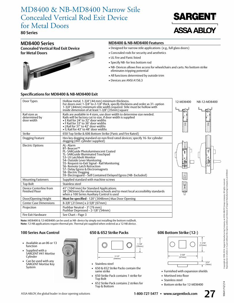
1-800-727-5477 • www.sargentlock.com 27
80 Series
9064
1:P
6/1/
14
Copy
right
© 1
998-
2014
, Sar
gent
Man
ufac
turin
g Co
mpa
ny, a
n AS
SA A
BLO
Y G
roup
com
pany
. All
right
s res
erve
d.
Re
prod
uctio
n in
who
le o
r in
part
with
out t
he e
xpre
ss w
ritte
n pe
rmis
sion
of S
arge
nt M
anuf
actu
ring
Com
pany
is p
rohi
bite
d.
NB-MD8400MD84008400WD8600 NB-WD8600NB-MD8600MD8600 NB-MD8400MD8400
8400WD8600 NB-WD8600NB-MD8600MD8600
NB-MD8400MD84008400WD8600 NB-WD8600NB-MD8600MD8600
12-MD8400 NB-12-MD8400
MD8400 & NB-MD8400 Features• Designed for narrow stile applications (e .g ., full glass doors)• Concealed rods for security and aesthetics• UL Fire and Panic listed• Specify NB- for less bottom rod • NB- Devices allows free access for wheelchairs and carts . No bottom strike
eliminates tripping potential• All functions determined by outside trim• Devices are ANSI A156 .3
MD8400 Series Concealed Vertical Rod Exit Device for Metal Doors
650 & 652 Strike Packs
• Stainless steel • 650 & 652 Strike Packs contain the
same strike • 650 Strike Pack contains 1 strike for
Top Bolt • 652 Strike Pack contains 2 strikes for
Top & Bottom
Door Types Hollow metal, 1-3/4" (44 mm) minimum thickness . For doors over 1-3/4" to 2-1/4" thick, specify thickness and order as 31- option 1-3/4" (44mm) minimum stile width required . Stile must be hollow with inside dimension of at least 1-3/8" (35mm) square Rail sizes as Rails are available in 4 sizes, use door width to determine size needed . determined by Rails will be factory cut to size, if door width is supplied door width • E Rail for 24" to 32" door widths • F Rail for 33" to 36" door widths • J Rail for 37" to 42" door widths • G Rail for 43" to 48" door widths Strike 650 Top Strike & 606 Bottom Strike (Panic and Fire Rated) Dogging Feature Hex key dogging standard on non fired rated devices; specify 16- for cylinder dogging (#41 cylinder supplied) Electric Options AL- Alarm BT- Beacon™ PL- SARGuide Photoluminescent Coated TL- SARGuide Illuminated Touchpad 53- LX Latchbolt Monitor 54- Outside Lever Monitoring 55- Request-to-Exit Signal - Rail Monitoring 56- Remote Latch Retraction 57- Delay Egress & Electromagnets 58- Electric Dogging 59- Electroguard – Self Contained Delayed Egress (NB- Excluded) Mounting Fasteners Supplied standard with machine screws Top Bolt Stainless steel Device Centerline from 41" (1041mm) for Standard Applications
Finished Floor 38" (965mm) for elementary schools and to meet local accessibility standards when a 100 Series Auxiliary Control is used
Door/Opening Height Must be specified - 120" (3048mm) Max Door Opening Center Case Dimensions 8-3/8" (213mm) x 2-5/8" (67mm) Projection Pushbar Neutral – 3" (76 mm)
Pushbar Depressed – 2-1/8" (54mm) Fire Exit Hardware See Chart – Page 3
Specifications for MD8400 & NB-MD8400 Exit
2-1/2" (64mm)
1-1/8"(29mm)
606 Bottom Strike (12-)
• Furnished with expansion shields • Mortised into floor • Stainless steel • Bottom strike for 12-MD8400
5/32" (4mm)
1-1/16" (27mm)
2-5/8" (67mm)
100 Series Aux Control
Note: MD8400 & 12-MD8400 can be used as NB- device by simply not installing the bottom rod/bolt . Note: 12-NB applications require thermal pin . Thermal pin supplied when ordered as a 12-NB device .
• Available as an 06 or 13 function
• Supplied with a SARGENT #41 Mortise Cylinder
• Can be used with any SARGENT Mortise Key System
MD8400 & NB-MD8400 Narrow StileConcealed Vertical Rod Exit Devicefor Metal Doors
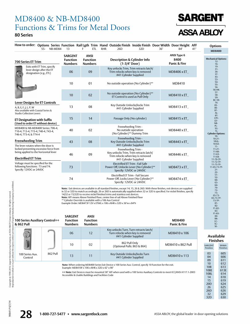
1-800-727-5477 • www.sargentlock.com28
80 Series
9064
1:P
6/1/
14
Copy
right
© 1
998-
2014
, Sar
gent
Man
ufac
turin
g Co
mpa
ny, a
n AS
SA A
BLO
Y G
roup
com
pany
. All
right
s res
erve
d.
Re
prod
uctio
n in
who
le o
r in
part
with
out t
he e
xpre
ss w
ritte
n pe
rmis
sion
of S
arge
nt M
anuf
actu
ring
Com
pany
is p
rohi
bite
d.
ANSI Type 6
Options
8400Panic & Fire
MD8400
Mechanical Options: 12- 16- 19- 31- 36- 37- 43- 53- 54- 55- 56-
56-HK- 57- 58- 59-
BC-59- 76-85-86-87- AL- BT-
CPC- LD-NB-PL-
SG- TL-
Cylinder Options: 10-
10-21- 10UL- 10-63-
11- 11-21- 11-60- 11-63- 11-64-
11-70-7P- 11-72-7P- 11-73-7P-
11-65-73-7P- 21- 22- 51- 52- 60- 63- 64- 70- 72- 73-
65-73- 65-73-7P-
73-7P- 81- 82-
F1-82- 83-
F1-83- 84- BR- LC-SC-SE-
Lever Designs for ET ControlsA, B, E, F, J, L, P, WAlso available with Coastal Series & Studio Collection Levers
Freewheeling TrimThe lever rotates when the door is locked preventing excessive force from being applied to the horizontal lever
Electrified ET TrimVoltage must be specified for the following functions: 73 and 74 . Specify: 12VDC or 24VDC
Note: Exit devices are available in all standard finishes, except 14, 15, 26 & 26D . With these finishes, exit devices are supplied in 32 or 32D to match accordingly . 26 or 26D is automatically supplied when 32 or 32D is specified . For nickel finishes, specify 14/32 or 15/32D to receive nickel finished trims and stainless exit devices .Note: AFF means Above Finished Floor, center line of rail Above Finished Floor** Cylinder Override is available with a 106 Aux Control Example Order: MD8473F 12V x ETMG x 106 x RHR x 32D x 36"w x 84"h
Available Finishes
SARGENT Finishes
BHMA Finishes
03 04 09 10
10B 10BE10BL
1415
20D26
26D32
32D
605 606 611 612 613
613E614618619624625626629 630
700 Series ET Trim Exits with ET Trim, specify
lever design after the ET designation (e .g ., ETL) 06 09
Key unlocks Trim, Trim retracts latch/ Trim relocks when key is removed
#41 Cylinder SuppliedMD8406 x ET_
10 01 No outside operation (No Cylinder)** MD8410
10 02 No outside operation (No Cylinder)** ET Control is used as Pull Only MD8410 x ET_
13 08 Key Outside Unlocks/locks Trim #41 Cylinder Supplied MD8413 x ET_
15 14 Passage Only (No cylinder) MD8415 x ET_
40 02Freewheeling Trim -
No outside operation (No Cylinder)** Dummy Trim
MD8440 x ET_
43 08Freewheeling Trim -
Key Outside Unlocks/locks Trim #41 Cylinder Supplied
MD8443 x ET_
46 09Freewheeling Trim -
Key unlocks Trim, Trim retracts latch/ Trim relocks when key is removed
#41 Cylinder Supplied
MD8446 x ET_
73Electrified ET Trim - Fail Safe
Power Off, Unlocks Lever (No Cylinder)**Specify: 12VDC or 24VDC
MD8473 x ET_
74Electrified ET Trim - Fail Secure
Power Off, Locks Lever (No Cylinder)**Specify: 12VDC or 24VDC
MD8474 x ET_
MD8400Panic & Fire
SARGENT Function Numbers
ANSIFunction Numbers
Description & Cylinder Info(1-3/4" Door)
Note: When ordering MD8400 Series Exit Device x 100 Series Aux . Control, specify 10 Function for the exit . Example: MD8410F x 106 x RHR x 32D x 42" x 90"
++ Note: Exit Devices must be mounted 38” AFF when used with a 100 Series Auxiliary Controls to meet ICC/ANSI A117 .1-2003 Accessible & Usable Buildings and Facilities Code
06 12Key unlocks Turn, Turn retracts latch/
Turn relocks when key is removed#41 Cylinder Supplied
MD8410 x 106
10 02 862 Pull Only(Optional Pulls: 863 & 864) MD8410 x 862 Pull
13 11 Key Outside Unlocks/locks Turn#41 Cylinder Supplied MD8410 x 113
862 Pull
SARGENT Function Numbers
100 Series Auxiliary Control++& 862 Pull
ANSIFunction Numbers
100 Series Aux . Control
ET Designation with Suffix (Used to order ET without device)MD8400 & NB-MD8400 Series: 706-4, 710-4, 713-4, 715-4, 740-4, 743-4, 746-4, 773-4, & 774-4
Options Series Function Rail Lgth Trim Hand Outside Finish Inside Finish Door Width Door Height AFF 55- NB-MD84 13 F ETL RHR 26D 32D 36" 84" 41"
How to order:
MD8400 & NB-MD8400Functions & Trims for Metal Doors
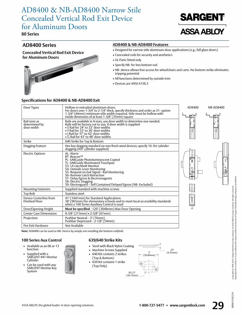
1-800-727-5477 • www.sargentlock.com 29
80 Series
9064
1:P
6/1/
14
Copy
right
© 1
998-
2014
, Sar
gent
Man
ufac
turin
g Co
mpa
ny, a
n AS
SA A
BLO
Y G
roup
com
pany
. All
right
s res
erve
d.
Re
prod
uctio
n in
who
le o
r in
part
with
out t
he e
xpre
ss w
ritte
n pe
rmis
sion
of S
arge
nt M
anuf
actu
ring
Com
pany
is p
rohi
bite
d.
NB-MD8400MD84008400WD8600 NB-WD8600NB-MD8600MD8600 NB-MD8400MD8400
8400WD8600 NB-WD8600NB-MD8600MD8600
NB-MD8400MD84008400WD8600 NB-WD8600NB-MD8600MD8600
AD8400 NB-AD8400
AD8400 & NB-AD8400 Features• Designed for narrow stile aluminum door applications (e .g ., full glass doors)• Concealed rods for security and aesthetics• UL Panic listed only• Specify NB- for less bottom rod • NB- device allows free access for wheelchairs and carts . No bottom strike eliminates
tripping potential• All functions determined by outside trim• Devices are ANSI A156 .3
AD8400 SeriesConcealed Vertical Rod Exit Device for Aluminum Doors
Door Types Hollow or extruded aluminum doors . For doors over 1-3/4" to 2-1/4" thick, specify thickness and order as 31- option 1-3/4" (44mm) minimum stile width required . Stile must be hollow with inside dimension of at least 1-3/8" (35mm) square Rail sizes as Rails are available in 4 sizes, use door width to determine size needed . determined by Rails will be factory cut to size, if door width is supplied door width • E Rail for 24" to 32" door widths • F Rail for 33" to 36" door widths • J Rail for 37" to 42" door widths • G Rail for 43" to 48" door widths Strike 640 Strike for Top & Bottom Dogging Feature Hex key dogging standard on non fired rated devices; specify 16- for cylinder dogging (#41 cylinder supplied) Electric Options AL- Alarm BT- Beacon™ PL- SARGuide Photoluminescent Coated TL- SARGuide Illuminated Touchpad 53- LX Latchbolt Monitor 54- Outside Lever Monitoring 55- Request-to-Exit Signal - Rail Monitoring 56- Remote Latch Retraction 57- Delay Egress & Electromagnets 58- Electric Dogging 59- Electroguard – Self Contained Delayed Egress (NB- Excluded) Mounting Fasteners Supplied standard with machine screws Top Bolt Stainless steel Device Centerline from 41" (1041mm) for Standard Applications
Finished Floor 38" (965mm) for elementary schools and to meet local accessibility standards when a 100 Series Auxiliary Control is used
Door/Opening Height Must be specified - 120" (3048mm) Max Door Opening Center Case Dimensions 8-3/8" (213mm) x 2-5/8" (67mm) Projection Pushbar Neutral – 3" (76mm)
Pushbar Depressed – 2-1/8" (54mm) Fire Exit Hardware Not Available
Specifications for AD8400 & NB-AD8400 Exit
Note: AD8400 can be used as NB- Device by simply not installing the bottom rod/bolt .
• Steel with Black Nylon Coating• Machine Screws Supplied• 640 Kit contains 2 strikes
(Top & Bottom)• 639 Kit contains 1 strike
(Top Only)
639/640 Strike Kits
2.00in50.80mm
1.21in30.73mm
.25in6.35mm
2" (50 .80mm)
.25" (6 .35mm)
Ø1 .21" (30 .73mm)
100 Series Aux Control • Available as an 06 or 13
function • Supplied with a
SARGENT #41 Mortise Cylinder
• Can be used with any SARGENT Mortise Key System
AD8400 & NB-AD8400 Narrow StileConcealed Vertical Rod Exit Devicefor Aluminum Doors
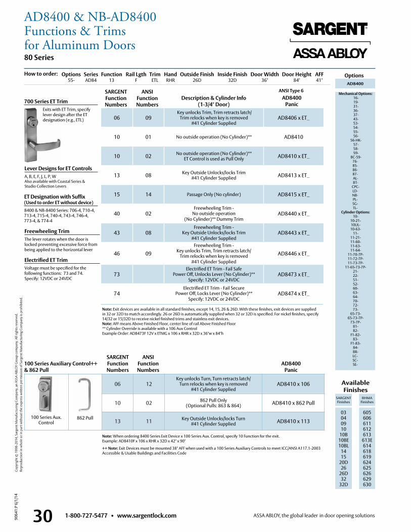
1-800-727-5477 • www.sargentlock.com30
80 Series
9064
1:P
6/1/
14
Copy
right
© 1
998-
2014
, Sar
gent
Man
ufac
turin
g Co
mpa
ny, a
n AS
SA A
BLO
Y G
roup
com
pany
. All
right
s res
erve
d.
Re
prod
uctio
n in
who
le o
r in
part
with
out t
he e
xpre
ss w
ritte
n pe
rmis
sion
of S
arge
nt M
anuf
actu
ring
Com
pany
is p
rohi
bite
d.
ANSI Type 6
Options
AD8400Panic
AD8400
Mechanical Options: 16- 19- 31- 36- 37- 43- 53- 54- 55- 56-
56-HK- 57- 58- 59-
BC-59- 76-85-86-87- AL- BT-
CPC- LD-NB-PL- SG- TL-
Cylinder Options: 10-
10-21- 10UL- 10-63-
11- 11-21- 11-60- 11-63- 11-64-
11-70-7P- 11-72-7P- 11-73-7P-
11-65-73-7P- 21- 22- 51- 52- 60- 63- 64- 70- 72- 73-
65-73- 65-73-7P-
73-7P- 81- 82-
F1-82- 83-
F1-83- 84- BR- LC-SC-SE-
Lever Designs for ET ControlsA, B, E, F, J, L, P, WAlso available with Coastal Series & Studio Collection Levers
Freewheeling TrimThe lever rotates when the door is locked preventing excessive force from being applied to the horizontal lever
Electrified ET TrimVoltage must be specified for the following functions: 73 and 74 . Specify: 12VDC or 24VDC
Note: Exit devices are available in all standard finishes, except 14, 15, 26 & 26D . With these finishes, exit devices are supplied in 32 or 32D to match accordingly . 26 or 26D is automatically supplied when 32 or 32D is specified . For nickel finishes, specify 14/32 or 15/32D to receive nickel finished trims and stainless exit devices .Note: AFF means Above Finished Floor, center line of rail Above Finished Floor** Cylinder Override is available with a 106 Aux Control Example Order: AD8473F 12V x ETMG x 106 x RHR x 32D x 36"w x 84"h
700 Series ET Trim Exits with ET Trim, specify
lever design after the ET designation (e .g ., ETL) 06 09
Key unlocks Trim, Trim retracts latch/ Trim relocks when key is removed
#41 Cylinder SuppliedAD8406 x ET_
10 01 No outside operation (No Cylinder)** AD8410
10 02 No outside operation (No Cylinder)** ET Control is used as Pull Only AD8410 x ET_
13 08 Key Outside Unlocks/locks Trim #41 Cylinder Supplied AD8413 x ET_
15 14 Passage Only (No cylinder) AD8415 x ET_
40 02Freewheeling Trim -
No outside operation (No Cylinder)** Dummy Trim
AD8440 x ET_
43 08Freewheeling Trim -
Key Outside Unlocks/locks Trim #41 Cylinder Supplied
AD8443 x ET_
46 09Freewheeling Trim -
Key unlocks Trim, Trim retracts latch/ Trim relocks when key is removed
#41 Cylinder Supplied
AD8446 x ET_
73Electrified ET Trim - Fail Safe
Power Off, Unlocks Lever (No Cylinder)**Specify: 12VDC or 24VDC
AD8473 x ET_
74Electrified ET Trim - Fail Secure
Power Off, Locks Lever (No Cylinder)**Specify: 12VDC or 24VDC
AD8474 x ET_
AD8400Panic
SARGENT Function Numbers
ANSIFunction Numbers
Description & Cylinder Info(1-3/4" Door)
Note: When ordering 8400 Series Exit Device x 100 Series Aux . Control, specify 10 Function for the exit . Example: AD8410F x 106 x RHR x 32D x 42" x 90"
++ Note: Exit Devices must be mounted 38" AFF when used with a 100 Series Auxiliary Controls to meet ICC/ANSI A117 .1-2003 Accessible & Usable Buildings and Facilities Code
06 12Key unlocks Turn, Turn retracts latch/
Turn relocks when key is removed#41 Cylinder Supplied
AD8410 x 106
10 02 862 Pull Only(Optional Pulls: 863 & 864) AD8410 x 862 Pull
13 11 Key Outside Unlocks/locks Turn#41 Cylinder Supplied AD8410 x 113
862 Pull
SARGENT Function Numbers
100 Series Auxiliary Control++& 862 Pull
ANSIFunction Numbers
100 Series Aux . Control
ET Designation with Suffix (Used to order ET without device)8400 & NB-8400 Series: 706-4, 710-4, 713-4, 715-4, 740-4, 743-4, 746-4, 773-4, & 774-4
Options Series Function Rail Lgth Trim Hand Outside Finish Inside Finish Door Width Door Height AFF 55- AD84 13 F ETL RHR 26D 32D 36" 84" 41"
How to order:
Available Finishes
SARGENT Finishes
BHMA Finishes
03 04 09 10
10B 10BE10BL
1415
20D26
26D32
32D
605 606 611 612 613
613E614618619624625626629 630
AD8400 & NB-AD8400Functions & Trimsfor Aluminum Doors
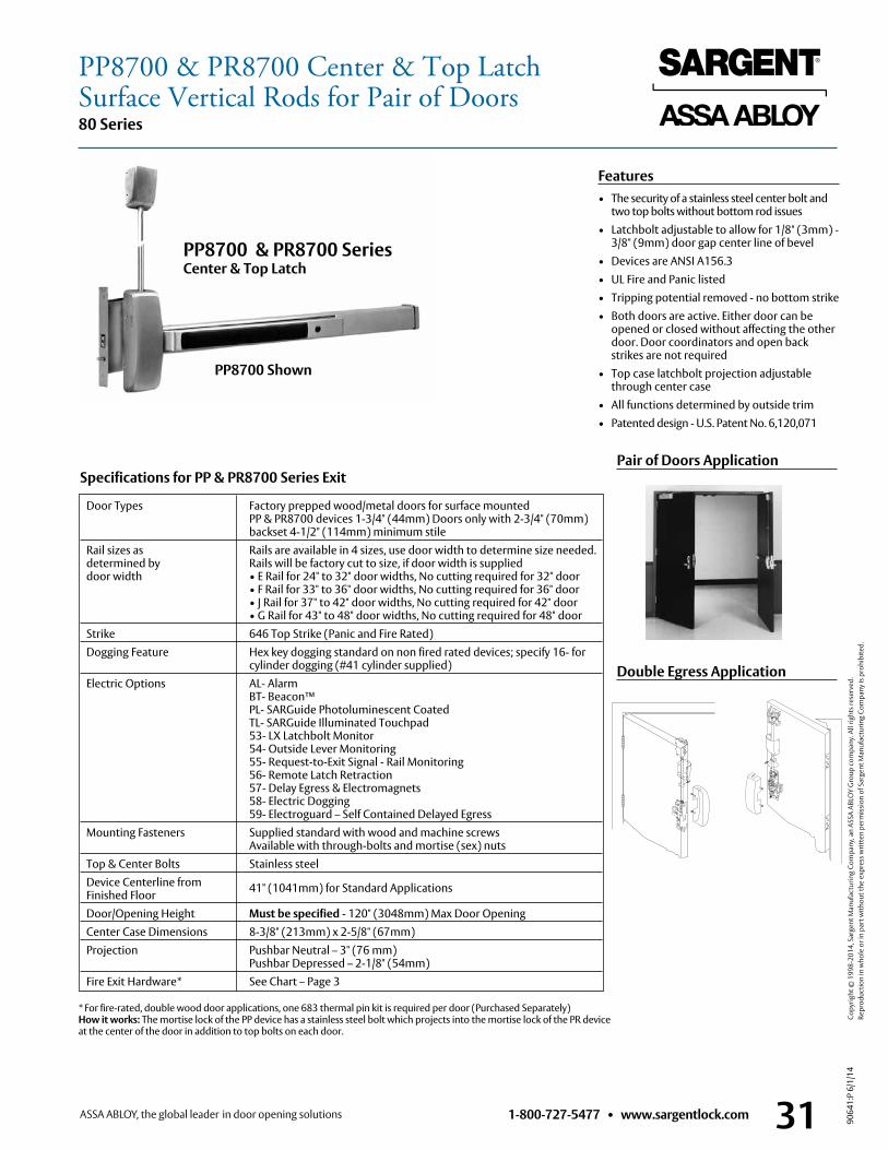
1-800-727-5477 • www.sargentlock.com 31
80 Series
9064
1:P
6/1/
14
Copy
right
© 1
998-
2014
, Sar
gent
Man
ufac
turin
g Co
mpa
ny, a
n AS
SA A
BLO
Y G
roup
com
pany
. All
right
s res
erve
d.
Re
prod
uctio
n in
who
le o
r in
part
with
out t
he e
xpre
ss w
ritte
n pe
rmis
sion
of S
arge
nt M
anuf
actu
ring
Com
pany
is p
rohi
bite
d.
Features• The security of a stainless steel center bolt and
two top bolts without bottom rod issues• Latchbolt adjustable to allow for 1/8" (3mm) -
3/8" (9mm) door gap center line of bevel• Devices are ANSI A156 .3• UL Fire and Panic listed• Tripping potential removed - no bottom strike• Both doors are active . Either door can be
opened or closed without affecting the other door . Door coordinators and open back strikes are not required
• Top case latchbolt projection adjustable through center case
• All functions determined by outside trim• Patented design - U .S . Patent No . 6,120,071
Door Types Factory prepped wood/metal doors for surface mounted PP & PR8700 devices 1-3/4" (44mm) Doors only with 2-3/4" (70mm) backset 4-1/2" (114mm) minimum stile
Rail sizes as Rails are available in 4 sizes, use door width to determine size needed . determined by Rails will be factory cut to size, if door width is supplied door width • E Rail for 24" to 32" door widths, No cutting required for 32" door • F Rail for 33" to 36" door widths, No cutting required for 36" door • J Rail for 37" to 42" door widths, No cutting required for 42" door • G Rail for 43" to 48" door widths, No cutting required for 48" door Strike 646 Top Strike (Panic and Fire Rated) Dogging Feature Hex key dogging standard on non fired rated devices; specify 16- for cylinder dogging (#41 cylinder supplied) Electric Options AL- Alarm BT- Beacon™ PL- SARGuide Photoluminescent Coated TL- SARGuide Illuminated Touchpad 53- LX Latchbolt Monitor 54- Outside Lever Monitoring 55- Request-to-Exit Signal - Rail Monitoring 56- Remote Latch Retraction 57- Delay Egress & Electromagnets 58- Electric Dogging 59- Electroguard – Self Contained Delayed Egress Mounting Fasteners Supplied standard with wood and machine screws
Available with through-bolts and mortise (sex) nuts Top & Center Bolts Stainless steel Device Centerline from 41" (1041mm) for Standard Applications Finished Floor Door/Opening Height Must be specified - 120" (3048mm) Max Door Opening Center Case Dimensions 8-3/8" (213mm) x 2-5/8" (67mm) Projection Pushbar Neutral – 3" (76 mm)
Pushbar Depressed – 2-1/8" (54mm) Fire Exit Hardware* See Chart – Page 3
Specifications for PP & PR8700 Series Exit
PP8700 & PR8700 Series Center & Top Latch
PP8700 Shown
* For fire-rated, double wood door applications, one 683 thermal pin kit is required per door (Purchased Separately) How it works: The mortise lock of the PP device has a stainless steel bolt which projects into the mortise lock of the PR device at the center of the door in addition to top bolts on each door .
Pair of Doors Application
Double Egress Application
PP8700 & PR8700 Center & Top LatchSurface Vertical Rods for Pair of Doors
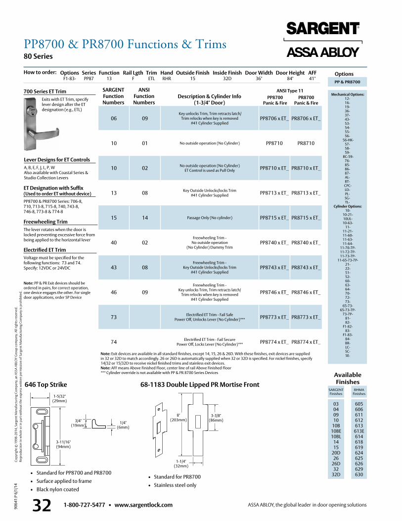
1-800-727-5477 • www.sargentlock.com32
80 Series
9064
1:P
6/1/
14
Copy
right
© 1
998-
2014
, Sar
gent
Man
ufac
turin
g Co
mpa
ny, a
n AS
SA A
BLO
Y G
roup
com
pany
. All
right
s res
erve
d.
Re
prod
uctio
n in
who
le o
r in
part
with
out t
he e
xpre
ss w
ritte
n pe
rmis
sion
of S
arge
nt M
anuf
actu
ring
Com
pany
is p
rohi
bite
d.
646 Top Strike
• Standard for PP8700 and PR8700 • Surface applied to frame • Black nylon coated
1-5/32"(29mm)
3-11/16"(94mm)
68-1183 Double Lipped PR Mortise Front
1-1/4" (32mm)
3/4" (19mm)
1/4" (6mm)
ANSI Type 11 Description & Cylinder Info
(1-3/4" Door)PP8700
Panic & FirePR8700
Panic & Fire
Lever Designs for ET ControlsA, B, E, F, J, L, P, WAlso available with Coastal Series &Studio Collection Levers
Freewheeling TrimThe lever rotates when the door is locked preventing excessive force from being applied to the horizontal lever
Electrified ET TrimVoltage must be specified for the following functions: 73 and 74 . Specify: 12VDC or 24VDC
Note: PP & PR Exit devices should be ordered in pairs, for correct operation, one device engages the other . For single door applications, order SP Device
700 Series ET Trim Exits with ET Trim, specify
lever design after the ET designation (e .g ., ETL)
06 09 Key unlocks Trim, Trim retracts latch/
Trim relocks when key is removed #41 Cylinder Supplied
PP8706 x ET_ PR8706 x ET_
10 01 No outside operation (No Cylinder) PP8710 PR8710
10 02 No outside operation (No Cylinder) ET Control is used as Pull Only PP8710 x ET_ PR8710 x ET_
13 08 Key Outside Unlocks/locks Trim #41 Cylinder Supplied PP8713 x ET_ PR8713 x ET_
15 14 Passage Only (No cylinder) PP8715 x ET_ PR8715 x ET_
40 02Freewheeling Trim -
No outside operation (No Cylinder) Dummy Trim
PP8740 x ET_ PR8740 x ET_
43 08Freewheeling Trim -
Key Outside Unlocks/locks Trim#41 Cylinder Supplied
PP8743 x ET_ PR8743 x ET_
46 09Freewheeling Trim -
Key unlocks Trim, Trim retracts latch/Trim relocks when key is removed
#41 Cylinder Supplied
PP8746 x ET_ PR8746 x ET_
73 Electrified ET Trim - Fail SafePower Off, Unlocks Lever (No Cylinder)*** PP8773 x ET_ PR8773 x ET_
74 Electrified ET Trim - Fail SecurePower Off, Locks Lever (No Cylinder)*** PP8774 x ET_ PR8774 x ET_
SARGENT Function Numbers
ANSIFunction Numbers
8" (203mm)
3-3/8" (86mm)
• Standard for PR8700• Stainless steel only
ET Designation with Suffix (Used to order ET without device)PP8700 & PR8700 Series: 706-8, 710, 713-8, 715-8, 740, 743-8, 746-8, 773-8 & 774-8
PP & PR8700
Mechanical Options: 12-16-19-36-37-43-53-54-55-56-
56-HK- 57- 58- 59-
BC-59- 76-85-86-87- AL- BT-
CPC- LD-PL- SG- TL-
Cylinder Options: 10-
10-21- 10UL- 10-63-
11- 11-21- 11-60- 11-63- 11-64-
11-70-7P- 11-72-7P- 11-73-7P-
11-65-73-7P- 21- 22- 51- 52- 60- 63- 64- 70- 72- 73-
65-73- 65-73-7P-
73-7P- 81- 82-
F1-82- 83-
F1-83- 84- BR- LC- SC- SE-
Options Series Function Rail Lgth Trim Hand Outside Finish Inside Finish Door Width Door Height AFF F1-83- PP87 13 F ETL RHR 15 32D 36" 84" 41"
How to order:
Available Finishes
SARGENT Finishes
BHMA Finishes
03 04 09 10
10B 10BE10BL
1415
20D26
26D32
32D
605 606 611 612 613
613E614618619624625626629 630
Options
Note: Exit devices are available in all standard finishes, except 14, 15, 26 & 26D . With these finishes, exit devices are supplied in 32 or 32D to match accordingly . 26 or 26D is automatically supplied when 32 or 32D is specified . For nickel finishes, specify 14/32 or 15/32D to receive nickel finished trims and stainless exit devices .Note: AFF means Above Finished Floor, center line of rail Above Finished Floor*** Cylinder override is not available with PP & PR 8700 Series Devices
PP8700 & PR8700 Functions & Trims
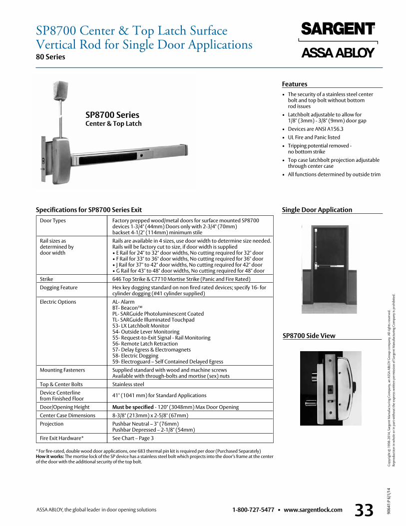
1-800-727-5477 • www.sargentlock.com 33
80 Series
9064
1:P
6/1/
14
Copy
right
© 1
998-
2014
, Sar
gent
Man
ufac
turin
g Co
mpa
ny, a
n AS
SA A
BLO
Y G
roup
com
pany
. All
right
s res
erve
d.
Re
prod
uctio
n in
who
le o
r in
part
with
out t
he e
xpre
ss w
ritte
n pe
rmis
sion
of S
arge
nt M
anuf
actu
ring
Com
pany
is p
rohi
bite
d.
Features• The security of a stainless steel center
bolt and top bolt without bottom rod issues
• Latchbolt adjustable to allow for 1/8" (3mm) - 3/8" (9mm) door gap
• Devices are ANSI A156 .3• UL Fire and Panic listed• Tripping potential removed -
no bottom strike• Top case latchbolt projection adjustable
through center case• All functions determined by outside trim
Door Types Factory prepped wood/metal doors for surface mounted SP8700 devices 1-3/4" (44mm) Doors only with 2-3/4" (70mm) backset 4-1/2" (114mm) minimum stile
Rail sizes as Rails are available in 4 sizes, use door width to determine size needed . determined by Rails will be factory cut to size, if door width is supplied door width • E Rail for 24" to 32" door widths, No cutting required for 32" door • F Rail for 33" to 36" door widths, No cutting required for 36" door • J Rail for 37" to 42" door widths, No cutting required for 42" door • G Rail for 43" to 48" door widths, No cutting required for 48" door Strike 646 Top Strike & C7710 Mortise Strike (Panic and Fire Rated) Dogging Feature Hex key dogging standard on non fired rated devices; specify 16- for cylinder dogging (#41 cylinder supplied) Electric Options AL- Alarm BT- Beacon™ PL- SARGuide Photoluminescent Coated TL- SARGuide Illuminated Touchpad 53- LX Latchbolt Monitor 54- Outside Lever Monitoring 55- Request-to-Exit Signal - Rail Monitoring 56- Remote Latch Retraction 57- Delay Egress & Electromagnets 58- Electric Dogging 59- Electroguard – Self Contained Delayed Egress Mounting Fasteners Supplied standard with wood and machine screws
Available with through-bolts and mortise (sex) nuts Top & Center Bolts Stainless steel Device Centerline 41" (1041 mm) for Standard Applications
from Finished Floor Door/Opening Height Must be specified - 120" (3048mm) Max Door Opening Center Case Dimensions 8-3/8" (213mm) x 2-5/8" (67mm) Projection Pushbar Neutral – 3" (76mm)
Pushbar Depressed – 2-1/8" (54mm) Fire Exit Hardware* See Chart – Page 3
Specifications for SP8700 Series Exit
SP8700 Series Center & Top Latch
* For fire-rated, double wood door applications, one 683 thermal pin kit is required per door (Purchased Separately) How it works: The mortise lock of the SP device has a stainless steel bolt which projects into the door’s frame at the center of the door with the additional security of the top bolt .
Single Door Application
SP8700 Side View
SP8700 Center & Top Latch SurfaceVertical Rod for Single Door Applications
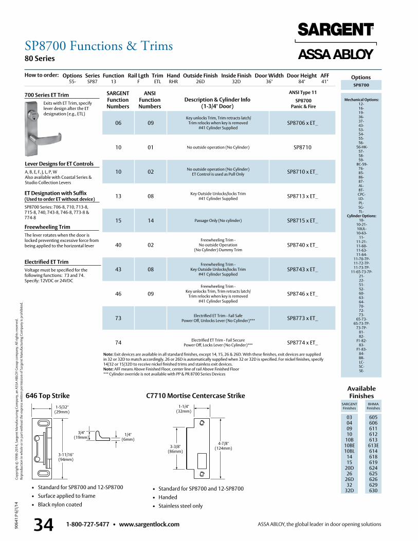
1-800-727-5477 • www.sargentlock.com34
80 Series
9064
1:P
6/1/
14
Copy
right
© 1
998-
2014
, Sar
gent
Man
ufac
turin
g Co
mpa
ny, a
n AS
SA A
BLO
Y G
roup
com
pany
. All
right
s res
erve
d.
Re
prod
uctio
n in
who
le o
r in
part
with
out t
he e
xpre
ss w
ritte
n pe
rmis
sion
of S
arge
nt M
anuf
actu
ring
Com
pany
is p
rohi
bite
d.
C7710 Mortise Centercase Strike
• Standard for SP8700 and 12-SP8700 • Handed • Stainless steel only
06 09 Key unlocks Trim, Trim retracts latch/
Trim relocks when key is removed #41 Cylinder Supplied
SP8706 x ET_
10 01 No outside operation (No Cylinder) SP8710
10 02 No outside operation (No Cylinder) ET Control is used as Pull Only SP8710 x ET_
13 08 Key Outside Unlocks/locks Trim #41 Cylinder Supplied SP8713 x ET_
15 14 Passage Only (No cylinder) SP8715 x ET_
40 02Freewheeling Trim -
No outside Operation (No Cylinder) Dummy Trim
SP8740 x ET_
43 08Freewheeling Trim -
Key Outside Unlocks/locks Trim#41 Cylinder Supplied
SP8743 x ET_
46 09Freewheeling Trim -
Key unlocks Trim, Trim retracts latch/Trim relocks when key is removed
#41 Cylinder Supplied
SP8746 x ET_
73 Electrified ET Trim - Fail SafePower Off, Unlocks Lever (No Cylinder)*** SP8773 x ET_
74 Electrified ET Trim - Fail SecurePower Off, Locks Lever (No Cylinder)*** SP8774 x ET_
ANSI Type 11 Description & Cylinder Info
(1-3/4" Door)SP8700
Panic & Fire
Lever Designs for ET ControlsA, B, E, F, J, L, P, WAlso available with Coastal Series & Studio Collection Levers
Freewheeling TrimThe lever rotates when the door is locked preventing excessive force from being applied to the horizontal lever
Electrified ET TrimVoltage must be specified for the following functions: 73 and 74 . Specify: 12VDC or 24VDC
700 Series ET Trim Exits with ET Trim, specify
lever design after the ET designation (e .g ., ETL)
SARGENT Function Numbers
ANSIFunction Numbers
646 Top Strike
• Standard for SP8700 and 12-SP8700 • Surface applied to frame • Black nylon coated
1-5/32"(29mm)
3-11/16"(94mm)
3/4" (19mm)
1/4" (6mm)
1-1/4"(32mm)
3-3/8"(86mm)
4-7/8"(124mm)
ET Designation with Suffix (Used to order ET without device)SP8700 Series: 706-8, 710, 713-8, 715-8, 740, 743-8, 746-8, 773-8 & 774-8
SP8700
Mechanical Options: 12-16-19-36-37-43-53-54-55-56-
56-HK- 57- 58- 59-
BC-59- 76-85-86-87- AL- BT-
CPC- LD-PL- SG- TL-
Cylinder Options: 10-
10-21- 10UL- 10-63-
11- 11-21- 11-60- 11-63- 11-64-
11-70-7P- 11-72-7P- 11-73-7P-
11-65-73-7P- 21- 22- 51- 52- 60- 63- 64- 70- 72- 73-
65-73- 65-73-7P-
73-7P- 81- 82-
F1-82- 83-
F1-83- 84- BR- LC- SC- SE-
Options Series Function Rail Lgth Trim Hand Outside Finish Inside Finish Door Width Door Height AFF 55- SP87 13 F ETL RHR 26D 32D 36" 84" 41"
How to order:
Available Finishes
SARGENT Finishes
BHMA Finishes
03 04 09 10
10B 10BE10BL
1415
20D26
26D32
32D
605 606 611 612 613
613E614618619624625626629 630
Options
Note: Exit devices are available in all standard finishes, except 14, 15, 26 & 26D . With these finishes, exit devices are supplied in 32 or 32D to match accordingly . 26 or 26D is automatically supplied when 32 or 32D is specified . For nickel finishes, specify 14/32 or 15/32D to receive nickel finished trims and stainless exit devices .Note: AFF means Above Finished Floor, center line of rail Above Finished Floor*** Cylinder override is not available with PP & PR 8700 Series Devices
SP8700 Functions & Trims
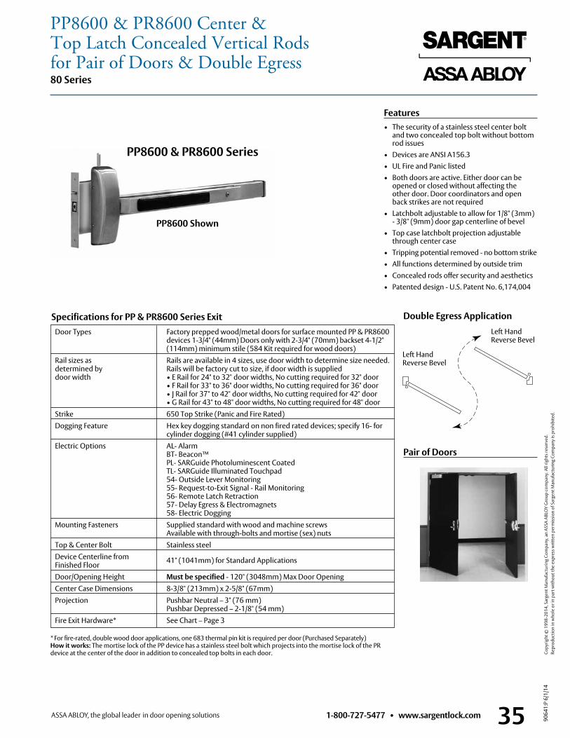
1-800-727-5477 • www.sargentlock.com 35
80 Series
9064
1:P
6/1/
14
Copy
right
© 1
998-
2014
, Sar
gent
Man
ufac
turin
g Co
mpa
ny, a
n AS
SA A
BLO
Y G
roup
com
pany
. All
right
s res
erve
d.
Re
prod
uctio
n in
who
le o
r in
part
with
out t
he e
xpre
ss w
ritte
n pe
rmis
sion
of S
arge
nt M
anuf
actu
ring
Com
pany
is p
rohi
bite
d.
Door Types Factory prepped wood/metal doors for surface mounted PP & PR8600 devices 1-3/4" (44mm) Doors only with 2-3/4" (70mm) backset 4-1/2" (114mm) minimum stile (584 Kit required for wood doors)
Rail sizes as Rails are available in 4 sizes, use door width to determine size needed . determined by Rails will be factory cut to size, if door width is supplied door width • E Rail for 24" to 32" door widths, No cutting required for 32" door • F Rail for 33" to 36" door widths, No cutting required for 36" door • J Rail for 37" to 42" door widths, No cutting required for 42" door • G Rail for 43" to 48" door widths, No cutting required for 48" door Strike 650 Top Strike (Panic and Fire Rated) Dogging Feature Hex key dogging standard on non fired rated devices; specify 16- for cylinder dogging (#41 cylinder supplied) Electric Options AL- Alarm BT- Beacon™ PL- SARGuide Photoluminescent Coated TL- SARGuide Illuminated Touchpad 54- Outside Lever Monitoring 55- Request-to-Exit Signal - Rail Monitoring 56- Remote Latch Retraction 57- Delay Egress & Electromagnets 58- Electric Dogging Mounting Fasteners Supplied standard with wood and machine screws
Available with through-bolts and mortise (sex) nuts Top & Center Bolt Stainless steel Device Centerline from 41" (1041mm) for Standard Applications Finished Floor Door/Opening Height Must be specified - 120" (3048mm) Max Door Opening Center Case Dimensions 8-3/8" (213mm) x 2-5/8" (67mm) Projection Pushbar Neutral – 3" (76 mm)
Pushbar Depressed – 2-1/8" (54 mm) Fire Exit Hardware* See Chart – Page 3
Features• The security of a stainless steel center bolt
and two concealed top bolt without bottom rod issues
• Devices are ANSI A156 .3• UL Fire and Panic listed• Both doors are active . Either door can be
opened or closed without affecting the other door . Door coordinators and open back strikes are not required
• Latchbolt adjustable to allow for 1/8" (3mm) - 3/8" (9mm) door gap centerline of bevel
• Top case latchbolt projection adjustable through center case
• Tripping potential removed - no bottom strike• All functions determined by outside trim• Concealed rods offer security and aesthetics• Patented design - U .S . Patent No . 6,174,004
Specifications for PP & PR8600 Series Exit
* For fire-rated, double wood door applications, one 683 thermal pin kit is required per door (Purchased Separately) How it works: The mortise lock of the PP device has a stainless steel bolt which projects into the mortise lock of the PR device at the center of the door in addition to concealed top bolts in each door .
PP8600 & PR8600 Series
PP8600 Shown
Left Hand Reverse Bevel
Left Hand Reverse Bevel
Double Egress Application
Pair of Doors
PP8600 & PR8600 Center & Top Latch Concealed Vertical Rods for Pair of Doors & Double Egress
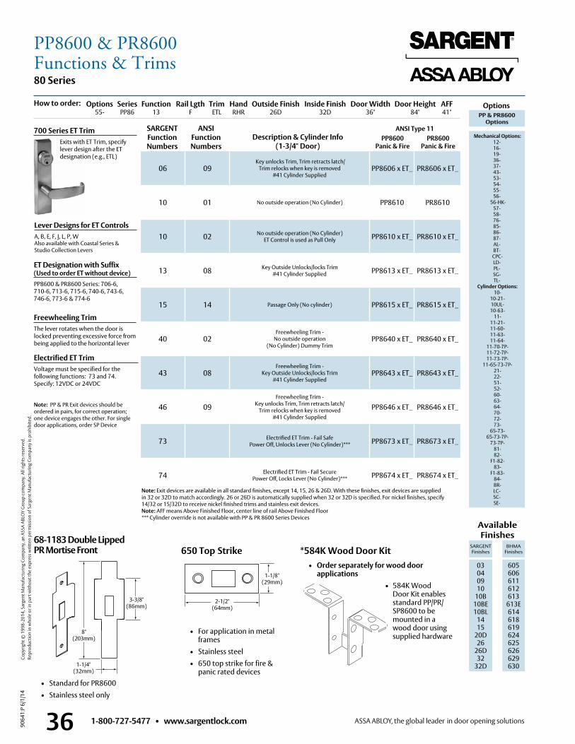
1-800-727-5477 • www.sargentlock.com36
80 Series
9064
1:P
6/1/
14
Copy
right
© 1
998-
2014
, Sar
gent
Man
ufac
turin
g Co
mpa
ny, a
n AS
SA A
BLO
Y G
roup
com
pany
. All
right
s res
erve
d.
Re
prod
uctio
n in
who
le o
r in
part
with
out t
he e
xpre
ss w
ritte
n pe
rmis
sion
of S
arge
nt M
anuf
actu
ring
Com
pany
is p
rohi
bite
d.
*584K Wood Door Kit • Order separately for wood door
applications • 584K Wood
Door Kit enables standard PP/PR/SP8600 to be mounted in a wood door using supplied hardware
68-1183 Double Lipped PR Mortise Front
• Standard for PR8600 • Stainless steel only
1-1/4" (32mm)
8" (203mm)
3-3/8" (86mm)
650 Top Strike
• For application in metal frames
• Stainless steel • 650 top strike for fire &
panic rated devices
2-1/2" (64mm)
1-1/8"(29mm)
ANSI Type 11 PP8600
Panic & FirePR8600
Panic & Fire
Lever Designs for ET ControlsA, B, E, F, J, L, P, WAlso available with Coastal Series & Studio Collection Levers
Freewheeling TrimThe lever rotates when the door is locked preventing excessive force from being applied to the horizontal lever
Electrified ET TrimVoltage must be specified for the following functions: 73 and 74 . Specify: 12VDC or 24VDC
700 Series ET Trim Exits with ET Trim, specify
lever design after the ET designation (e .g ., ETL)
06 09 Key unlocks Trim, Trim retracts latch/
Trim relocks when key is removed #41 Cylinder Supplied
PP8606 x ET_ PR8606 x ET_
10 01 No outside operation (No Cylinder) PP8610 PR8610
10 02 No outside operation (No Cylinder) ET Control is used as Pull Only PP8610 x ET_ PR8610 x ET_
13 08 Key Outside Unlocks/locks Trim #41 Cylinder Supplied PP8613 x ET_ PR8613 x ET_
15 14 Passage Only (No cylinder) PP8615 x ET_ PR8615 x ET_
40 02Freewheeling Trim -
No outside operation (No Cylinder) Dummy Trim
PP8640 x ET_ PR8640 x ET_
43 08Freewheeling Trim -
Key Outside Unlocks/locks Trim#41 Cylinder Supplied
PP8643 x ET_ PR8643 x ET_
46 09Freewheeling Trim -
Key unlocks Trim, Trim retracts latch/Trim relocks when key is removed
#41 Cylinder Supplied
PP8646 x ET_ PR8646 x ET_
73 Electrified ET Trim - Fail SafePower Off, Unlocks Lever (No Cylinder)*** PP8673 x ET_ PR8673 x ET_
74 Electrified ET Trim - Fail SecurePower Off, Locks Lever (No Cylinder)*** PP8674 x ET_ PR8674 x ET_
SARGENT Function Numbers
ANSIFunction Numbers
Description & Cylinder Info(1-3/4" Door)
Note: Exit devices are available in all standard finishes, except 14, 15, 26 & 26D . With these finishes, exit devices are supplied in 32 or 32D to match accordingly . 26 or 26D is automatically supplied when 32 or 32D is specified . For nickel finishes, specify 14/32 or 15/32D to receive nickel finished trims and stainless exit devices .Note: AFF means Above Finished Floor, center line of rail Above Finished Floor*** Cylinder override is not available with PP & PR 8600 Series Devices
Note: PP & PR Exit devices should be ordered in pairs, for correct operation; one device engages the other . For single door applications, order SP Device
ET Designation with Suffix (Used to order ET without device)PP8600 & PR8600 Series: 706-6, 710-6, 713-6, 715-6, 740-6, 743-6, 746-6, 773-6 & 774-6
PP & PR8600Options
Mechanical Options: 12-16-19-36-37-43-53-54-55-56-
56-HK- 57- 58- 76- 85- 86-87- AL- BT-
CPC- LD-PL- SG- TL-
Cylinder Options: 10-
10-21- 10UL- 10-63-
11- 11-21- 11-60- 11-63- 11-64-
11-70-7P- 11-72-7P- 11-73-7P-
11-65-73-7P- 21- 22- 51- 52- 60- 63- 64- 70- 72- 73-
65-73- 65-73-7P-
73-7P- 81- 82-
F1-82- 83-
F1-83- 84- BR- LC-SC-SE-
Options Series Function Rail Lgth Trim Hand Outside Finish Inside Finish Door Width Door Height AFF 55- PP86 13 F ETL RHR 26D 32D 36" 84" 41"
How to order:
Available Finishes
SARGENT Finishes
BHMA Finishes
03 04 09 10
10B 10BE10BL
1415
20D26
26D32
32D
605 606 611 612 613
613E614618619624625626629 630
Options
PP8600 & PR8600Functions & Trims
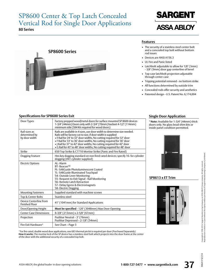
1-800-727-5477 • www.sargentlock.com 37
80 Series
9064
1:P
6/1/
14
Copy
right
© 1
998-
2014
, Sar
gent
Man
ufac
turin
g Co
mpa
ny, a
n AS
SA A
BLO
Y G
roup
com
pany
. All
right
s res
erve
d.
Re
prod
uctio
n in
who
le o
r in
part
with
out t
he e
xpre
ss w
ritte
n pe
rmis
sion
of S
arge
nt M
anuf
actu
ring
Com
pany
is p
rohi
bite
d.
Features• The security of a stainless steel center bolt
and a concealed top bolt without bottom rod issues
• Devices are ANSI A156 .3• UL Fire and Panic listed• Latchbolt adjustable to allow for 1/8" (3mm)
- 3/8" (9mm) door gap centerline of bevel• Top case latchbolt projection adjustable
through center case• Tripping potential removed - no bottom strike• All functions determined by outside trim• Concealed rods offer security and aesthetics• Patented design - U .S . Patent No . 6,174,004
Door Types Factory prepped wood/metal doors for surface mounted SP 8600 devices 1-3/4" (44mm) Doors only with 2-3/4" (70mm) backset 4-1/2" (114mm) minimum stile (584 Kit required for wood doors)
Rail sizes as Rails are available in 4 sizes, use door width to determine size needed . determined by Rails will be factory cut to size, if door width is supplied by door width • E Rail for 24" to 32" door widths, No cutting required for 32" door • F Rail for 33" to 36" door widths, No cutting required for 36" door • J Rail for 37" to 42" door widths, No cutting required for 42" door • G Rail for 43" to 48" door widths, No cutting required for 48" door Strike 650 Top Strike & C7710 Mortise Strike (Panic and Fire Rated) Dogging Feature Hex key dogging standard on non fired rated devices; specify 16- for cylinder dogging (#41 cylinder supplied) Electric Options AL- Alarm BT- Beacon™ PL- SARGuide Photoluminescent Coated TL- SARGuide Illuminated Touchpad 54- Outside Lever Monitoring 55- Request-to-Exit Signal - Rail Monitoring 56- Remote Latch Retraction 57- Delay Egress & Electromagnets 58- Electric Dogging Mounting Fasteners Supplied standard with machine screws Top & Center Bolts Stainless steel Device Centerline from 41" (1041mm) for Standard Applications Finished Floor Door/Opening Height Must be specified - 120" (3048mm) Max Door Opening Center Case Dimensions 8-3/8" (213mm) x 2-5/8" (67mm) Projection Pushbar Neutral – 3" (76mm)
Pushbar Depressed – 2-1/8" (54mm) Fire Exit Hardware* See Chart – Page 3
Specifications for SP8600 Series Exit Single Door Application* Note: Available for 1-3/4" (44mm) thick doors only . No glass bead shim kits or inside panel condition permitted .
SP8613 x ET Trim
* For fire-rated, double wood door applications, one 683 thermal pin kit is required per door (Purchased Separately) How it works: The mortise lock of the SP device has a stainless steel bolt which projects into the door frame at the center of the door with the additional security of a concealed top bolt .
SP8600 Series
SP8600 Center & Top Latch ConcealedVertical Rod for Single Door Applications
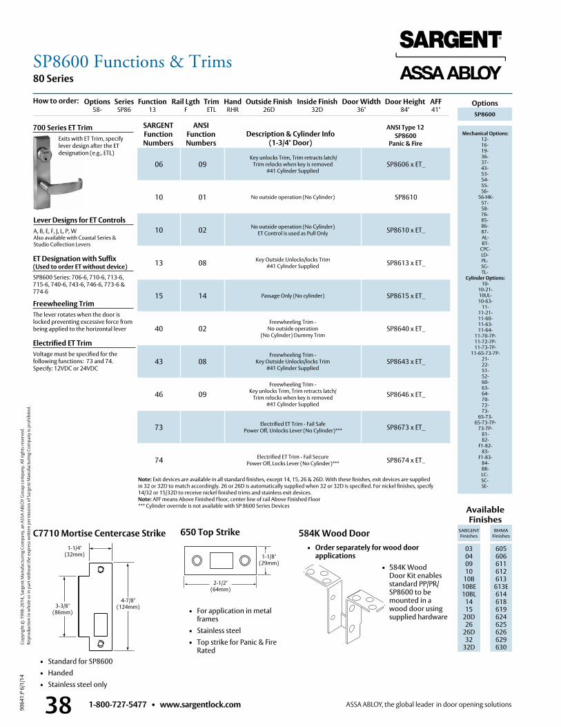
1-800-727-5477 • www.sargentlock.com38
80 Series
9064
1:P
6/1/
14
Copy
right
© 1
998-
2014
, Sar
gent
Man
ufac
turin
g Co
mpa
ny, a
n AS
SA A
BLO
Y G
roup
com
pany
. All
right
s res
erve
d.
Re
prod
uctio
n in
who
le o
r in
part
with
out t
he e
xpre
ss w
ritte
n pe
rmis
sion
of S
arge
nt M
anuf
actu
ring
Com
pany
is p
rohi
bite
d.
C7710 Mortise Centercase Strike
ANSI Type 12
1-1/4"(32mm)
3-3/8"(86mm)
4-7/8"(124mm)
SP8600 Panic & Fire
Lever Designs for ET ControlsA, B, E, F, J, L, P, WAlso available with Coastal Series & Studio Collection Levers
Freewheeling TrimThe lever rotates when the door is locked preventing excessive force from being applied to the horizontal lever
Electrified ET TrimVoltage must be specified for the following functions: 73 and 74 . Specify: 12VDC or 24VDC
700 Series ET Trim Exits with ET Trim, specify
lever design after the ET designation (e .g ., ETL)
06 09 Key unlocks Trim, Trim retracts latch/
Trim relocks when key is removed #41 Cylinder Supplied
SP8606 x ET_
10 01 No outside operation (No Cylinder) SP8610
10 02 No outside operation (No Cylinder) ET Control is used as Pull Only SP8610 x ET_
13 08 Key Outside Unlocks/locks Trim #41 Cylinder Supplied SP8613 x ET_
15 14 Passage Only (No cylinder) SP8615 x ET_
40 02Freewheeling Trim -
No outside operation (No Cylinder) Dummy Trim
SP8640 x ET_
43 08Freewheeling Trim -
Key Outside Unlocks/locks Trim#41 Cylinder Supplied
SP8643 x ET_
46 09Freewheeling Trim -
Key unlocks Trim, Trim retracts latch/Trim relocks when key is removed
#41 Cylinder Supplied
SP8646 x ET_
73 Electrified ET Trim - Fail SafePower Off, Unlocks Lever (No Cylinder)*** SP8673 x ET_
74 Electrified ET Trim - Fail SecurePower Off, Locks Lever (No Cylinder)*** SP8674 x ET_
SARGENT Function Numbers
ANSIFunction Numbers
Description & Cylinder Info(1-3/4" Door)
584K Wood Door • Order separately for wood door
applications • 584K Wood
Door Kit enables standard PP/PR/SP8600 to be mounted in a wood door using supplied hardware
• Standard for SP8600• Handed• Stainless steel only
650 Top Strike
• For application in metal frames
• Stainless steel • Top strike for Panic & Fire
Rated
2-1/2" (64mm)
Note: Exit devices are available in all standard finishes, except 14, 15, 26 & 26D . With these finishes, exit devices are supplied in 32 or 32D to match accordingly . 26 or 26D is automatically supplied when 32 or 32D is specified . For nickel finishes, specify 14/32 or 15/32D to receive nickel finished trims and stainless exit devices .Note: AFF means Above Finished Floor, center line of rail Above Finished Floor*** Cylinder override is not available with SP 8600 Series Devices
ET Designation with Suffix (Used to order ET without device)SP8600 Series: 706-6, 710-6, 713-6, 715-6, 740-6, 743-6, 746-6, 773-6 & 774-6
1-1/8"(29mm)
SP8600
Mechanical Options: 12-16-19-36-37-43-53-54-55-56-
56-HK- 57- 58- 76- 85- 86-87- AL- BT-
CPC- LD-PL- SG- TL-
Cylinder Options: 10-
10-21- 10UL- 10-63-
11- 11-21- 11-60- 11-63- 11-64-
11-70-7P- 11-72-7P- 11-73-7P-
11-65-73-7P- 21- 22- 51- 52- 60- 63- 64- 70- 72- 73-
65-73- 65-73-7P-
73-7P- 81- 82-
F1-82- 83-
F1-83- 84- BR- LC-SC-SE-
Options Series Function Rail Lgth Trim Hand Outside Finish Inside Finish Door Width Door Height AFF 58- SP86 13 F ETL RHR 26D 32D 36" 84" 41"
How to order:
Available Finishes
SARGENT Finishes
BHMA Finishes
03 04 09 10
10B 10BE10BL
1415
20D26
26D32
32D
605 606 611 612 613
613E614618619624625626629 630
Options
SP8600 Functions & Trims
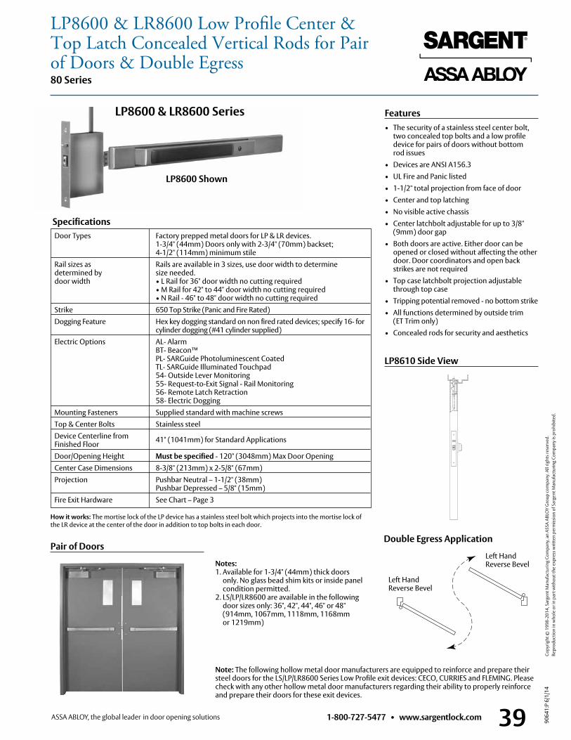
1-800-727-5477 • www.sargentlock.com 39
80 Series
9064
1:P
6/1/
14
Copy
right
© 1
998-
2014
, Sar
gent
Man
ufac
turin
g Co
mpa
ny, a
n AS
SA A
BLO
Y G
roup
com
pany
. All
right
s res
erve
d.
Re
prod
uctio
n in
who
le o
r in
part
with
out t
he e
xpre
ss w
ritte
n pe
rmis
sion
of S
arge
nt M
anuf
actu
ring
Com
pany
is p
rohi
bite
d.
Door Types Factory prepped metal doors for LP & LR devices . 1-3/4" (44mm) Doors only with 2-3/4" (70mm) backset; 4-1/2" (114mm) minimum stile
Rail sizes as Rails are available in 3 sizes, use door width to determine determined by size needed . door width • L Rail for 36" door width no cutting required • M Rail for 42" to 44" door width no cutting required • N Rail - 46" to 48" door width no cutting required Strike 650 Top Strike (Panic and Fire Rated) Dogging Feature Hex key dogging standard on non fired rated devices; specify 16- for cylinder dogging (#41 cylinder supplied) Electric Options AL- Alarm BT- Beacon™ PL- SARGuide Photoluminescent Coated TL- SARGuide Illuminated Touchpad 54- Outside Lever Monitoring 55- Request-to-Exit Signal - Rail Monitoring 56- Remote Latch Retraction 58- Electric Dogging Mounting Fasteners Supplied standard with machine screws Top & Center Bolts Stainless steel Device Centerline from 41" (1041mm) for Standard Applications
Finished Floor Door/Opening Height Must be specified - 120" (3048mm) Max Door Opening Center Case Dimensions 8-3/8" (213mm) x 2-5/8" (67mm) Projection Pushbar Neutral – 1-1/2" (38mm)
Pushbar Depressed – 5/8" (15mm) Fire Exit Hardware See Chart – Page 3
Features• The security of a stainless steel center bolt,
two concealed top bolts and a low profile device for pairs of doors without bottom rod issues
• Devices are ANSI A156 .3• UL Fire and Panic listed• 1-1/2" total projection from face of door• Center and top latching• No visible active chassis• Center latchbolt adjustable for up to 3/8"
(9mm) door gap• Both doors are active . Either door can be
opened or closed without affecting the other door . Door coordinators and open back strikes are not required
• Top case latchbolt projection adjustable through top case
• Tripping potential removed - no bottom strike• All functions determined by outside trim
(ET Trim only)• Concealed rods for security and aesthetics
Specifications
Note: The following hollow metal door manufacturers are equipped to reinforce and prepare their steel doors for the LS/LP/LR8600 Series Low Profile exit devices: CECO, CURRIES and FLEMING . Please check with any other hollow metal door manufacturers regarding their ability to properly reinforce and prepare their doors for these exit devices .
Notes:1 . Available for 1-3/4" (44mm) thick doors
only . No glass bead shim kits or inside panel condition permitted .
2 . LS/LP/LR8600 are available in the following door sizes only: 36", 42", 44", 46" or 48" (914mm, 1067mm, 1118mm, 1168mm or 1219mm)
LP8600 & LR8600 Series
How it works: The mortise lock of the LP device has a stainless steel bolt which projects into the mortise lock of the LR device at the center of the door in addition to top bolts in each door .
Left Hand Reverse Bevel
Left Hand Reverse Bevel
Double Egress Application
LP8610 Side View
Pair of Doors
LP8600 Shown
LP8600 & LR8600 Low Profile Center & Top Latch Concealed Vertical Rods for Pair of Doors & Double Egress
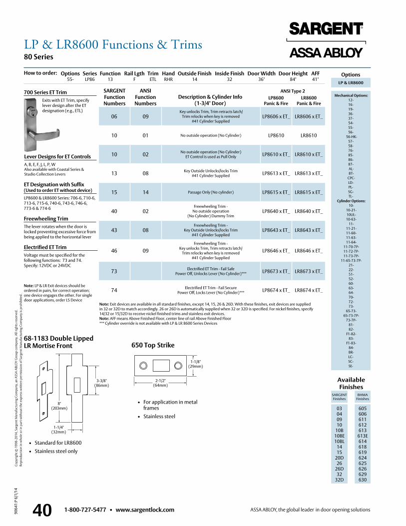
1-800-727-5477 • www.sargentlock.com40
80 Series
9064
1:P
6/1/
14
Copy
right
© 1
998-
2014
, Sar
gent
Man
ufac
turin
g Co
mpa
ny, a
n AS
SA A
BLO
Y G
roup
com
pany
. All
right
s res
erve
d.
Re
prod
uctio
n in
who
le o
r in
part
with
out t
he e
xpre
ss w
ritte
n pe
rmis
sion
of S
arge
nt M
anuf
actu
ring
Com
pany
is p
rohi
bite
d.
ANSI Type 2 LP8600 LR8600 Panic & Fire Panic & Fire
Lever Designs for ET ControlsA, B, E, F, J, L, P, WAlso available with Coastal Series & Studio Collection Levers
Freewheeling TrimThe lever rotates when the door is locked preventing excessive force from being applied to the horizontal lever
Electrified ET TrimVoltage must be specified for the following functions: 73 and 74 . Specify: 12VDC or 24VDC
Note: Exit devices are available in all standard finishes, except 14, 15, 26 & 26D . With these finishes, exit devices are supplied in 32 or 32D to match accordingly . 26 or 26D is automatically supplied when 32 or 32D is specified . For nickel finishes, specify 14/32 or 15/32D to receive nickel finished trims and stainless exit devices .Note: AFF means Above Finished Floor, center line of rail Above Finished Floor*** Cylinder override is not available with LP & LR 8600 Series Devices
Note: LP & LR Exit devices should be ordered in pairs, for correct operation; one device engages the other . For single door applications, order LS Device
700 Series ET Trim Exits with ET Trim, specify
lever design after the ET designation (e .g ., ETL)
06 09 Key unlocks Trim, Trim retracts latch/
Trim relocks when key is removed #41 Cylinder Supplied
LP8606 x ET_ LR8606 x ET_
10 01 No outside operation (No Cylinder) LP8610 LR8610
10 02 No outside operation (No Cylinder) ET Control is used as Pull Only LP8610 x ET_ LR8610 x ET_
13 08 Key Outside Unlocks/locks Trim #41 Cylinder Supplied LP8613 x ET_ LR8613 x ET_
15 14 Passage Only (No cylinder) LP8615 x ET_ LR8615 x ET_
40 02Freewheeling Trim -
No outside operation (No Cylinder) Dummy Trim
LP8640 x ET_ LR8640 x ET_
43 08Freewheeling Trim -
Key Outside Unlocks/locks Trim #41 Cylinder Supplied
LP8643 x ET_ LR8643 x ET_
46 09Freewheeling Trim -
Key unlocks Trim, Trim retracts latch/ Trim relocks when key is removed
#41 Cylinder Supplied
LP8646 x ET_ LR8646 x ET_
73 Electrified ET Trim - Fail Safe Power Off, Unlocks Lever (No Cylinder)*** LP8673 x ET_ LR8673 x ET_
74 Electrified ET Trim - Fail Secure Power Off, Locks Lever (No Cylinder)*** LP8674 x ET_ LR8674 x ET_
SARGENT Function Numbers
ANSIFunction Numbers
Description & Cylinder Info(1-3/4" Door)
68-1183 Double Lipped LR Mortise Front
• Standard for LR8600 • Stainless steel only
1-1/4" (32mm)
8" (203mm)
3-3/8" (86mm)
650 Top Strike
• For application in metal frames
• Stainless steel
2-1/2" (64mm)
1-1/8"(29mm)
ET Designation with Suffix (Used to order ET without device)LP8600 & LR8600 Series: 706-6, 710-6, 713-6, 715-6, 740-6, 743-6, 746-6, 773-6 & 774-6
LP & LR8600
Mechanical Options:12-16-19-36-37-54-55-56-
56-HK- 57- 58- 76- 85- 86-87- AL- BT-
CPC- LD-PL- SG- TL-
Cylinder Options: 10-
10-21- 10UL- 10-63-
11- 11-21- 11-60- 11-63- 11-64-
11-70-7P- 11-72-7P- 11-73-7P-
11-65-73-7P- 21- 22- 51- 52- 60- 63- 64- 70- 72- 73-
65-73- 65-73-7P-
73-7P- 81- 82-
F1-82- 83-
F1-83- 84- BR- LC-SC-SE-
Options Series Function Rail Lgth Trim Hand Outside Finish Inside Finish Door Width Door Height AFF 55- LP86 13 F ETL RHR 14 32 36" 84" 41"
How to order:
Available Finishes
SARGENT Finishes
BHMA Finishes
03 04 09 10
10B 10BE10BL
1415
20D26
26D32
32D
605 606 611 612 613
613E614618619624625626629 630
Options
LP & LR8600 Functions & Trims
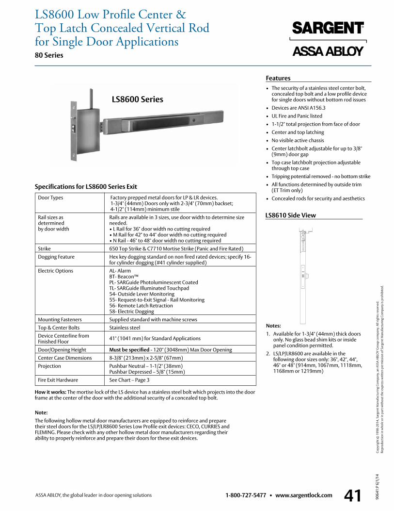
1-800-727-5477 • www.sargentlock.com 41
80 Series
9064
1:P
6/1/
14
Copy
right
© 1
998-
2014
, Sar
gent
Man
ufac
turin
g Co
mpa
ny, a
n AS
SA A
BLO
Y G
roup
com
pany
. All
right
s res
erve
d.
Re
prod
uctio
n in
who
le o
r in
part
with
out t
he e
xpre
ss w
ritte
n pe
rmis
sion
of S
arge
nt M
anuf
actu
ring
Com
pany
is p
rohi
bite
d.
Features• The security of a stainless steel center bolt,
concealed top bolt and a low profile device for single doors without bottom rod issues
• Devices are ANSI A156 .3• UL Fire and Panic listed• 1-1/2" total projection from face of door• Center and top latching• No visible active chassis• Center latchbolt adjustable for up to 3/8"
(9mm) door gap• Top case latchbolt projection adjustable
through top case• Tripping potential removed - no bottom strike• All functions determined by outside trim
(ET Trim only)• Concealed rods for security and aesthetics Door Types Factory prepped metal doors for LP & LR devices .
1-3/4" (44mm) Doors only with 2-3/4" (70mm) backset; 4-1/2" (114mm) minimum stile
Rail sizes as Rails are available in 3 sizes, use door width to determine size determined needed . by door width • L Rail for 36" door width no cutting required • M Rail for 42" to 44" door width no cutting required • N Rail - 46" to 48" door width no cutting required Strike 650 Top Strike & C7710 Mortise Strike (Panic and Fire Rated) Dogging Feature Hex key dogging standard on non fired rated devices; specify 16- for cylinder dogging (#41 cylinder supplied) Electric Options AL- Alarm BT- Beacon™ PL- SARGuide Photoluminescent Coated TL- SARGuide Illuminated Touchpad 54- Outside Lever Monitoring 55- Request-to-Exit Signal - Rail Monitoring 56- Remote Latch Retraction 58- Electric Dogging Mounting Fasteners Supplied standard with machine screws Top & Center Bolts Stainless steel Device Centerline from 41" (1041 mm) for Standard Applications
Finished Floor Door/Opening Height Must be specified - 120" (3048mm) Max Door Opening Center Case Dimensions 8-3/8" (213mm) x 2-5/8" (67mm) Projection Pushbar Neutral – 1-1/2" (38mm)
Pushbar Depressed – 5/8" (15mm) Fire Exit Hardware See Chart – Page 3
Specifications for LS8600 Series Exit
LS8600 Series
LS8610 Side View
Notes:1 . Available for 1-3/4" (44mm) thick doors only . No glass bead shim kits or inside
panel condition permitted .2 . LS/LP/LR8600 are available in the
following door sizes only: 36", 42", 44", 46" or 48" (914mm, 1067mm, 1118mm, 1168mm or 1219mm)
Note:The following hollow metal door manufacturers are equipped to reinforce and prepare their steel doors for the LS/LP/LR8600 Series Low Profile exit devices: CECO, CURRIES and FLEMING . Please check with any other hollow metal door manufacturers regarding their ability to properly reinforce and prepare their doors for these exit devices .
How it works: The mortise lock of the LS device has a stainless steel bolt which projects into the door frame at the center of the door with the additional security of a concealed top bolt .
LS8600 Low Profile Center & Top Latch Concealed Vertical Rod for Single Door Applications
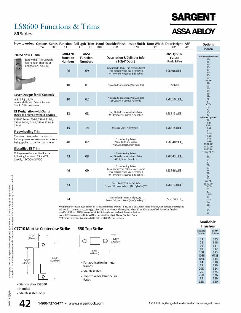
1-800-727-5477 • www.sargentlock.com42
80 Series
9064
1:P
6/1/
14
Copy
right
© 1
998-
2014
, Sar
gent
Man
ufac
turin
g Co
mpa
ny, a
n AS
SA A
BLO
Y G
roup
com
pany
. All
right
s res
erve
d.
Re
prod
uctio
n in
who
le o
r in
part
with
out t
he e
xpre
ss w
ritte
n pe
rmis
sion
of S
arge
nt M
anuf
actu
ring
Com
pany
is p
rohi
bite
d.
C7710 Mortise Centercase Strike
06 09 Key unlocks Trim, Trim retracts latch/
Trim relocks when key is removed #41 Cylinder Required & Supplied
LS8606 x ET_
10 01 No outside operation (No Cylinder) LS8610
10 02 No outside operation (No Cylinder) ET Control is used as Pull Only LS8610 x ET_
13 08 Key Outside Unlocks/locks Trim #41 Cylinder Required & Supplied LS8613 x ET_
15 14 Passage Only (No cylinder) LS8615 x ET_
40 02Freewheeling Trim -
No outside operation (No Cylinder) Dummy Trim
LS8640 x ET_
43 08Freewheeling Trim -
Key Outside Unlocks/locks Trim#41 Cylinder Supplied
LS8643 x ET_
46 09Freewheeling Trim -
Key unlocks Trim, Trim retracts latch/Trim relocks when key is removed#41 Cylinder Required & Supplied
LS8646 x ET_
73 Electrified ET Trim - Fail SafePower Off, Unlocks Lever (No Cylinder)*** LS8673 x ET_
74 Electrified ET Trim - Fail SecurePower Off, Locks Lever (No Cylinder)*** LS8674 x ET_
ANSI Type 12 LS8600
Panic & Fire
Lever Designs for ET ControlsA, B, E, F, J, L, P, W Also available with Coastal Series & Studio Collection Levers
Freewheeling TrimThe lever rotates when the door is locked preventing excessive force from being applied to the horizontal lever
Electrified ET TrimVoltage must be specified for the following functions: 73 and 74 . Specify: 12VDC or 24VDC
Note: Exit devices are available in all standard finishes, except 14, 15, 26 & 26D . With these finishes, exit devices are supplied in 32 or 32D to match accordingly . 26 or 26D is automatically supplied when 32 or 32D is specified . For nickel finishes, specify 14/32 or 15/32D to receive nickel finished trims and stainless exit devices .Note: AFF means Above Finished Floor, center line of rail Above Finished Floor*** Cylinder override is not available with LP 8700 Series Devices
700 Series ET Trim Exits with ET Trim, specify
lever design after the ET designation (e .g ., ETL)
SARGENT Function Numbers
ANSIFunction Numbers
Description & Cylinder Info(1-3/4" Door)
1-1/4"(32mm)
3-3/8"(86mm)
4-7/8"(124mm)
• Standard for LS8600• Handed• Stainless steel only
650 Top Strike
• For application in metal frames
• Stainless steel • Top strike for Panic & Fire
Rated
2-1/2" (64mm)
ET Designation with Suffix (Used to order ET without device)LS8600 Series: 706-6, 710-6, 713-6, 715-6, 740-6, 743-6, 746-6, 773-6 & 774-6
1-1/8"(29mm)
LS8600
Mechanical Options:12-16-19-36-37-54-55-56-
56-HK- 57- 58- 76- 85- 86-87- AL- BT-
CPC- LD-PL- SG- TL-
Cylinder Options: 10-
10-21- 10UL- 10-63-
11- 11-21- 11-60- 11-63- 11-64-
11-70-7P- 11-72-7P- 11-73-7P-
11-65-73-7P- 21- 22- 51- 52- 60- 63- 64- 70- 72- 73-
65-73- 65-73-7P-
73-7P- 81- 82-
F1-82- 83-
F1-83- 84- BR- LC-SC-SE-
Options Series Function Rail Lgth Trim Hand Outside Finish Inside Finish Door Width Door Height AFF 55- LP86 13 F ETL RHR 26D 32D 36" 84" 41"
How to order:
Available Finishes
SARGENT Finishes
BHMA Finishes
03 04 09 10
10B 10BE10BL
1415
20D26
26D32
32D
605 606 611 612 613
613E614618619624625626629 630
Options
LS8600 Functions & Trims
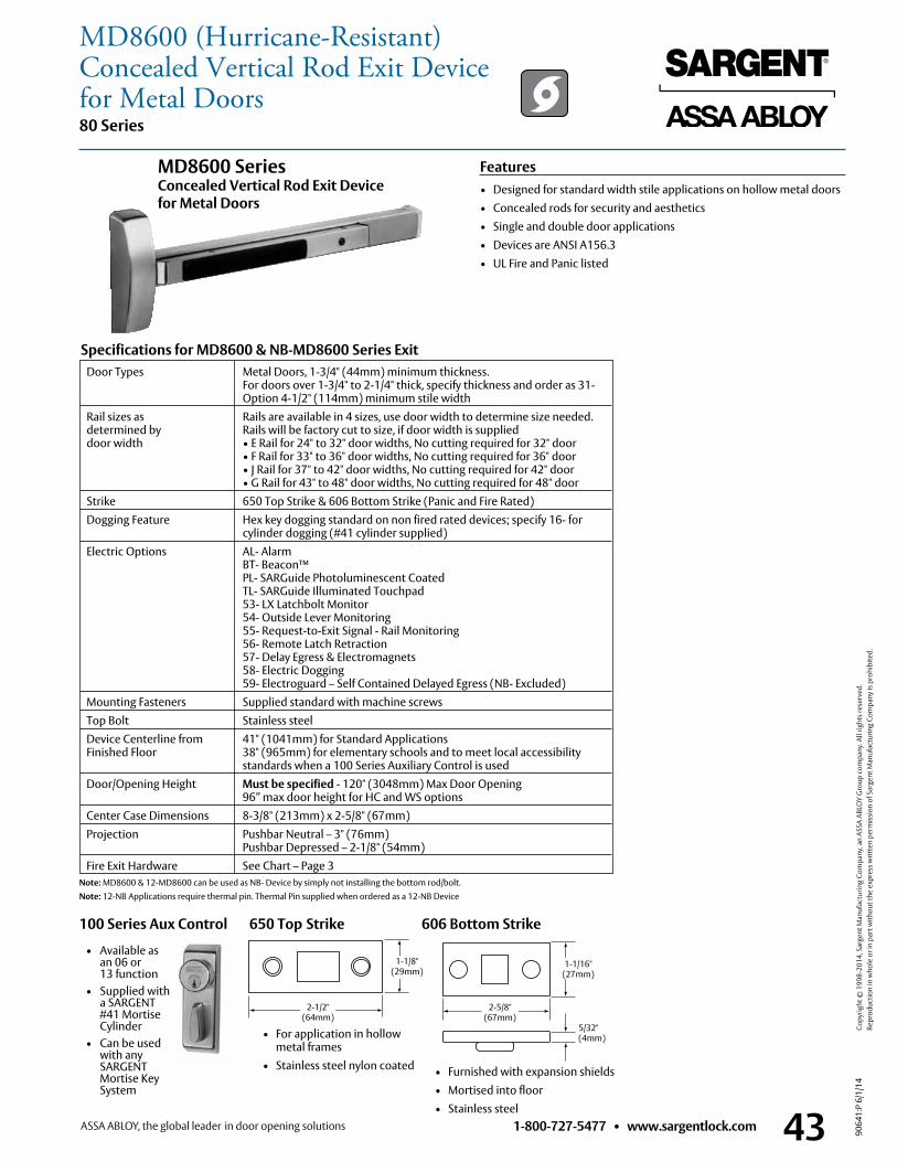
1-800-727-5477 • www.sargentlock.com 43
80 Series
9064
1:P
6/1/
14
Copy
right
© 1
998-
2014
, Sar
gent
Man
ufac
turin
g Co
mpa
ny, a
n AS
SA A
BLO
Y G
roup
com
pany
. All
right
s res
erve
d.
Re
prod
uctio
n in
who
le o
r in
part
with
out t
he e
xpre
ss w
ritte
n pe
rmis
sion
of S
arge
nt M
anuf
actu
ring
Com
pany
is p
rohi
bite
d.
606 Bottom Strike
• Furnished with expansion shields • Mortised into floor • Stainless steel
Door Types Metal Doors, 1-3/4" (44mm) minimum thickness . For doors over 1-3/4" to 2-1/4" thick, specify thickness and order as 31- Option 4-1/2" (114mm) minimum stile width
Rail sizes as Rails are available in 4 sizes, use door width to determine size needed . determined by Rails will be factory cut to size, if door width is supplied door width • E Rail for 24" to 32" door widths, No cutting required for 32" door • F Rail for 33" to 36" door widths, No cutting required for 36" door • J Rail for 37" to 42" door widths, No cutting required for 42" door • G Rail for 43" to 48" door widths, No cutting required for 48" door Strike 650 Top Strike & 606 Bottom Strike (Panic and Fire Rated) Dogging Feature Hex key dogging standard on non fired rated devices; specify 16- for cylinder dogging (#41 cylinder supplied) Electric Options AL- Alarm BT- Beacon™ PL- SARGuide Photoluminescent Coated TL- SARGuide Illuminated Touchpad 53- LX Latchbolt Monitor 54- Outside Lever Monitoring 55- Request-to-Exit Signal - Rail Monitoring 56- Remote Latch Retraction 57- Delay Egress & Electromagnets 58- Electric Dogging 59- Electroguard – Self Contained Delayed Egress (NB- Excluded) Mounting Fasteners Supplied standard with machine screws Top Bolt Stainless steel Device Centerline from 41" (1041mm) for Standard Applications Finished Floor 38" (965mm) for elementary schools and to meet local accessibility standards when a 100 Series Auxiliary Control is used Door/Opening Height Must be specified - 120" (3048mm) Max Door Opening
96” max door height for HC and WS options Center Case Dimensions 8-3/8" (213mm) x 2-5/8" (67mm) Projection Pushbar Neutral – 3" (76mm)
Pushbar Depressed – 2-1/8" (54mm) Fire Exit Hardware See Chart – Page 3
Specifications for MD8600 & NB-MD8600 Series Exit
Features• Designed for standard width stile applications on hollow metal doors• Concealed rods for security and aesthetics• Single and double door applications• Devices are ANSI A156 .3• UL Fire and Panic listed
MD8600 Series Concealed Vertical Rod Exit Device for Metal Doors
650 Top Strike
• For application in hollow metal frames
• Stainless steel nylon coated
2-1/2" (64mm)
1-1/8"(29mm)
5/32" (4mm)
1-1/16" (27mm)
2-5/8" (67mm)
Note: MD8600 & 12-MD8600 can be used as NB- Device by simply not installing the bottom rod/bolt . Note: 12-NB Applications require thermal pin . Thermal Pin supplied when ordered as a 12-NB Device
100 Series Aux Control
• Available as an 06 or 13 function
• Supplied with a SARGENT #41 Mortise Cylinder
• Can be used with any SARGENT Mortise Key System
MD8600 (Hurricane-Resistant)Concealed Vertical Rod Exit Device for Metal Doors
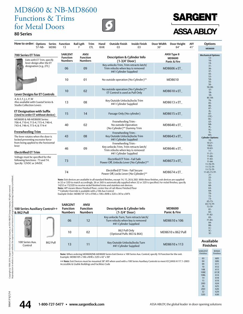
1-800-727-5477 • www.sargentlock.com44
80 Series
9064
1:P
6/1/
14
Copy
right
© 1
998-
2014
, Sar
gent
Man
ufac
turin
g Co
mpa
ny, a
n AS
SA A
BLO
Y G
roup
com
pany
. All
right
s res
erve
d.
Re
prod
uctio
n in
who
le o
r in
part
with
out t
he e
xpre
ss w
ritte
n pe
rmis
sion
of S
arge
nt M
anuf
actu
ring
Com
pany
is p
rohi
bite
d.
ANSI Type 8
Options
Lever Designs for ET ControlsA, B, E, F, J, L, P, WAlso available with Coastal Series & Studio Collection Levers
Freewheeling TrimThe lever rotates when the door is locked preventing excessive force from being applied to the horizontal lever
Electrified ET TrimVoltage must be specified for the following functions: 73 and 74 . Specify: 12VDC or 24VDC
Note: Exit devices are available in all standard finishes, except 14, 15, 26 & 26D . With these finishes, exit devices are supplied in 32 or 32D to match accordingly . 26 or 26D is automatically supplied when 32 or 32D is specified . For nickel finishes, specify 14/32 or 15/32D to receive nickel finished trims and stainless exit devices .Note: AFF means Above Finished Floor, center line of rail Above Finished Floor** Cylinder Override is available with a 106 Aux ControlExample Order: MD8673F 12V x ETMG x 106 x RHR x 32D x 36"w x 84"h
Available Finishes
SARGENT Finishes
BHMA Finishes
03 04 09 10
10B 10BE10BL
1415
20D26
26D32
32D
605 606 611 612 613
613E614618619624625626629 630
700 Series ET Trim Exits with ET Trim, specify
lever design after the ET designation (e .g ., ETL)
Options Series Function Rail Lgth Trim Hand Outside Finish Inside Finish Door Width Door Height AFF57-NB- MD86 13 F ETL RHR 03 03 36" 84" 41"
06 09 Key unlocks Trim, Trim retracts latch/
Trim relocks when key is removed #41 Cylinder Supplied
MD8606 x ET_
10 01 No outside operation (No Cylinder)** MD8610
10 02 No outside operation (No Cylinder)** ET Control is used as Pull Only MD8610 x ET_
13 08 Key Outside Unlocks/locks Trim #41 Cylinder Supplied MD8613 x ET_
15 14 Passage Only (No cylinder) MD8615 x ET_
40 02Freewheeling Trim -
No outside Operation (No Cylinder)** Dummy Trim
MD8640 x ET_
43 08Freewheeling Trim -
Key Outside Unlocks/locks Trim #41 Cylinder Supplied
MD8643 x ET_
46 09
Freewheeling Trim - Key unlocks Trim, Trim retracts latch/
Trim relocks when key is removed #41 Cylinder Supplied
MD8646 x ET_
73 Electrified ET Trim - Fail Safe Power Off, Unlocks Lever (No Cylinder)** MD8673 x ET_
74 Electrified ET Trim - Fail Secure Power Off, Locks Lever (No Cylinder)** MD8674 x ET_
MD8600
Mechanical Options: 12- 16- 19- 31- 36- 37- 43- 53- 54- 55- 56-
56-HK- 57- 58- 59-
BC-59- 76-85-86-87- AL- BT-
CPC-HC- LD- NB- PL- SG- TL-
WS- Cylinder Options:
10- 10-21- 10UL- 10-63-
11- 11-21- 11-60- 11-63- 11-64-
11-70-7P- 11-72-7P- 11-73-7P-
11-65-73-7P- 21- 22- 51- 52- 60- 63- 64- 70- 72- 73-
65-73- 65-73-7P-
73-7P- 81- 82-
F1-82- 83-
F1-83- 84- BR- LC-SC-SE-
Note: When ordering MD8600/NB-MD8600 Series Exit Device x 100 Series Aux . Control, specify 10 Function for the exit . Example: MD8610F x 106 x RHR x 32D x 42" x 90"
++ Note: Exit Devices must be mounted 38" AFF when used with a 100 Series Auxiliary Controls to meet ICC/ANSI A117 .1-2003 Accessible & Usable Buildings and Facilities Code
MD8600Panic & Fire
Description & Cylinder Info(1-3/4" Door)
SARGENT Function Numbers
ANSIFunction Numbers
MD8600 Panic & Fire
How to order:
06 12Key unlocks Turn, Turn retracts latch/
Turn relocks when key is removed#41 Cylinder Supplied
MD8610 x 106
10 02 862 Pull Only(Optional Pulls: 863 & 864) MD8610 x 862 Pull
13 11 Key Outside Unlocks/locks Turn#41 Cylinder Supplied MD8610 x 113 862 Pull
SARGENT Function Numbers
Description & Cylinder Info(1-3/4" Door)
100 Series Auxiliary Control++& 862 Pull
ANSIFunction Numbers
100 Series Aux . Control
ET Designation with Suffix (Used to order ET without device)MD8600 & NB-MD8600 Series: 706-4, 710-4, 713-4, 715-4, 740-4, 743-4, 746-4, 773-4, & 774-4
MD8600 & NB-MD8600Functions & Trimsfor Metal Doors
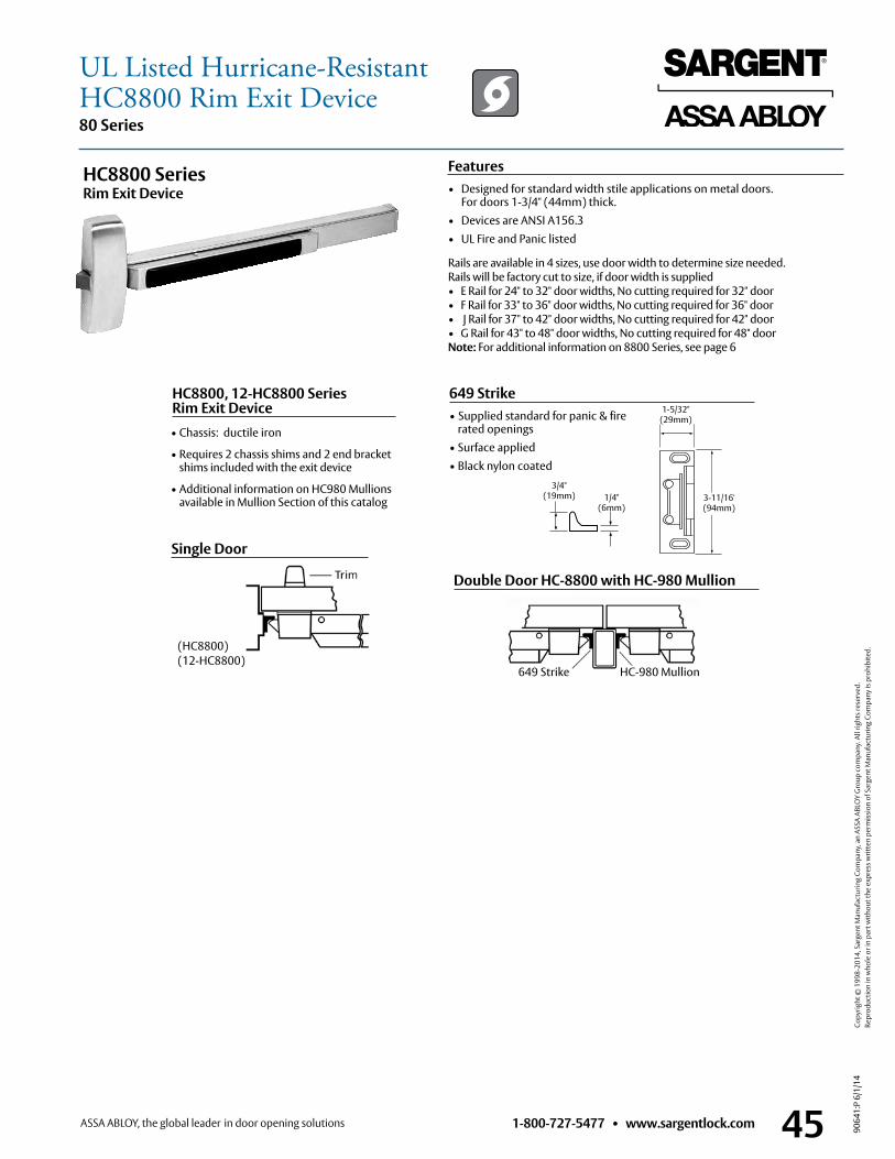
1-800-727-5477 • www.sargentlock.com 45
80 Series
9064
1:P
6/1/
14
Copy
right
© 1
998-
2014
, Sar
gent
Man
ufac
turin
g Co
mpa
ny, a
n AS
SA A
BLO
Y G
roup
com
pany
. All
right
s res
erve
d.
Re
prod
uctio
n in
who
le o
r in
part
with
out t
he e
xpre
ss w
ritte
n pe
rmis
sion
of S
arge
nt M
anuf
actu
ring
Com
pany
is p
rohi
bite
d.
Rails are available in 4 sizes, use door width to determine size needed . Rails will be factory cut to size, if door width is supplied • E Rail for 24" to 32" door widths, No cutting required for 32" door • F Rail for 33" to 36" door widths, No cutting required for 36" door • J Rail for 37" to 42" door widths, No cutting required for 42" door • G Rail for 43" to 48" door widths, No cutting required for 48" door Note: For additional information on 8800 Series, see page 6
HC8800 Series Rim Exit Device
Double Door HC-8800 with HC-980 Mullion
649 Strike HC-980 Mullion
• Chassis: ductile iron
• Requires 2 chassis shims and 2 end bracket shims included with the exit device
• Additional information on HC980 Mullions available in Mullion Section of this catalog
HC8800, 12-HC8800 Series Rim Exit Device
649 Strike• Supplied standard for panic & fire
rated openings• Surface applied• Black nylon coated
3/4" (19mm) 1/4"
(6mm)
1-5/32"(29mm)
3-11/16'(94mm)
Single Door (HC8800) (12-HC8800)
Features• Designed for standard width stile applications on metal doors .
For doors 1-3/4" (44mm) thick .• Devices are ANSI A156 .3 • UL Fire and Panic listed
UL Listed Hurricane-ResistantHC8800 Rim Exit Device
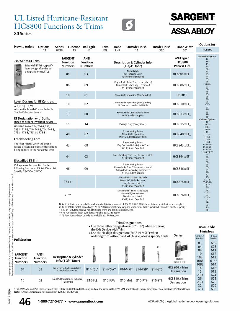
1-800-727-5477 • www.sargentlock.com46
80 Series
9064
1:P
6/1/
14
Copy
right
© 1
998-
2014
, Sar
gent
Man
ufac
turin
g Co
mpa
ny, a
n AS
SA A
BLO
Y G
roup
com
pany
. All
right
s res
erve
d.
Re
prod
uctio
n in
who
le o
r in
part
with
out t
he e
xpre
ss w
ritte
n pe
rmis
sion
of S
arge
nt M
anuf
actu
ring
Com
pany
is p
rohi
bite
d.
04 03Night Latch
Key Retracts Latch #34 Cylinder Supplied
HC8804 x ET_
06 09 Key unlocks Trim, Trim retracts latch/
Trim relocks when key is removed #41 Cylinder Supplied
HC8806 x ET_
10 01 No outside operation (No Cylinder) HC8810
10 02 No outside operation (No Cylinder) ET Control is used as Pull Only HC8810 x ET_
13 08 Key Outside Unlocks/locks Trim #41 Cylinder Supplied HC8813 x ET_
15 14 Passage Only (No cylinder) HC8815 x ET_
40 02Freewheeling Trim -
No outside operation (No Cylinder) Dummy Trim
HC8840 x ET_
43 08Freewheeling Trim -
Key Outside Unlocks/locks Trim#41 Cylinder Supplied
HC8843 x ET_
44 03 Freewheeling Trim - Key Retracts Latch #34 Cylinder Supplied HC8844 x ET_
46 09Freewheeling Trim -
Key unlocks Trim, Trim retracts latch/ Trim relocks when key is removed
#41 Cylinder Supplied
HC8846 x ET_
75++Electrified ET Trim - Fail Safe
Power Off, Unlocks Lever, Key Retracts Latch
#34 Cylinder Supplied
HC8875 x ET_
76**Electrified ET Trim - Fail Secure
Power Off, Locks Lever, \Key Retracts Latch
#34 Cylinder Supplied
HC8876 x ET_
ANSI Type 1
Options for
Description & Cylinder Info (1-3/4" Door)
HC8800Panic & Fire
HC8800
Mechanical Options: 12- 16- 19- 31- 36- 37- 43- 54- 55- 56-
56-HK- 57- 58- 76-85-86-87- BT-
CPC- LD- PL- SG- TB- TL-
Cylinder Options: 10-
10-21- 10UL- 10-63-
11- 11-21- 11-60- 11-63- 11-64-
11-70-7P- 11-72-7P- 11-73-7P-
11-65-73-7P- 21- 22- 51- 52- 60- 63- 64- 70- 72- 73-
65-73- 65-73-7P-
73-7P- 81- 82-
F1-82- 83-
F1-83- 84- BR- LC-SC-SE-
Freewheeling TrimThe lever rotates when the door is locked preventing excessive force from being applied to the horizontal lever
Note: Exit devices are available in all standard finishes, except 14, 15, 26 & 26D . With these finishes, exit devices are supplied in 32 or 32D to match accordingly . 26 or 26D is automatically supplied when 32 or 32D is specified . For nickel finishes, specify 14/32 or 15/32D to receive nickel finished trims and stainless exit devices .++ 75 Function without cylinder is available as a 73 Function** 76 Function without cylinder is available as a 74 Function
Description & Cylinder Info. (1-3/4" Door)
Available Finishes
SARGENT Finishes
BHMA Finishes
03 04 09 10
10B 10BE10BL
1415
20D26
26D32
32D
605 606 611 612 613
613E614618619624625626629630* FSL, FSW, MSL and PSB trims are used with (HC-& 12-) 8888 and 8804 only and are the same as FLL, FLW, MAL and PTB pulls except for cylinder hole located 3/8" (9mm) lower
Note: FLW & FSW trims are not available in 32(629) or 32D(630)
700 Series ET Trim Exits with ET Trim, specify
lever design after the ET designation (e .g ., ETL)
Options Series Function Rail Lgth Trim Hand Outside Finish Inside Finish Door Width 12 HC88 13 F ETL RHR 15 32D 36"
04 03 Night Latch-Key Retracts Latch#34 Cylinder Supplied 814-FSL* 814-FSW* 814-MSL* 814-PSB* 814-STS HC8804 x Trim
Designation
10 02 No O/S Operation or Cylinder(Pull Only) 810-FLL 810-FLW 810-MAL 810-PTB 810-STS HC8810 x Trim
Designation
HC800Panic & Fire
Series
SARGENT Function Numbers
ANSIFunction Numbers
SARGENT Function Numbers
ANSIFunction Numbers
How to order:
Lever Designs for ET ControlsA, B, E, F, J, L, P, WAlso available with Coastal Series &Studio Collection Levers
Electrified ET TrimVoltage must be specified for the following functions: 73, 74, 75 and 76 . Specify: 12VDC or 24VDC
Pull Section
ET Designation with Suffix (Used to order ET without device)HC-8800 Series: 704, 706-8, 710, 713-8, 715-8, 740, 743-8, 744, 746-8, 773-8, 774-8, 775-8 & 776-8
Trim Designations• Use three letter designations (Ex “PTB”) when ordering
the Exit Device with Trim• Use the six digit designation (Ex “814-MSL”) when
ordering trim without an Exit Device, always specify finish
UL Listed Hurricane-ResistantHC8800 Functions & Trims
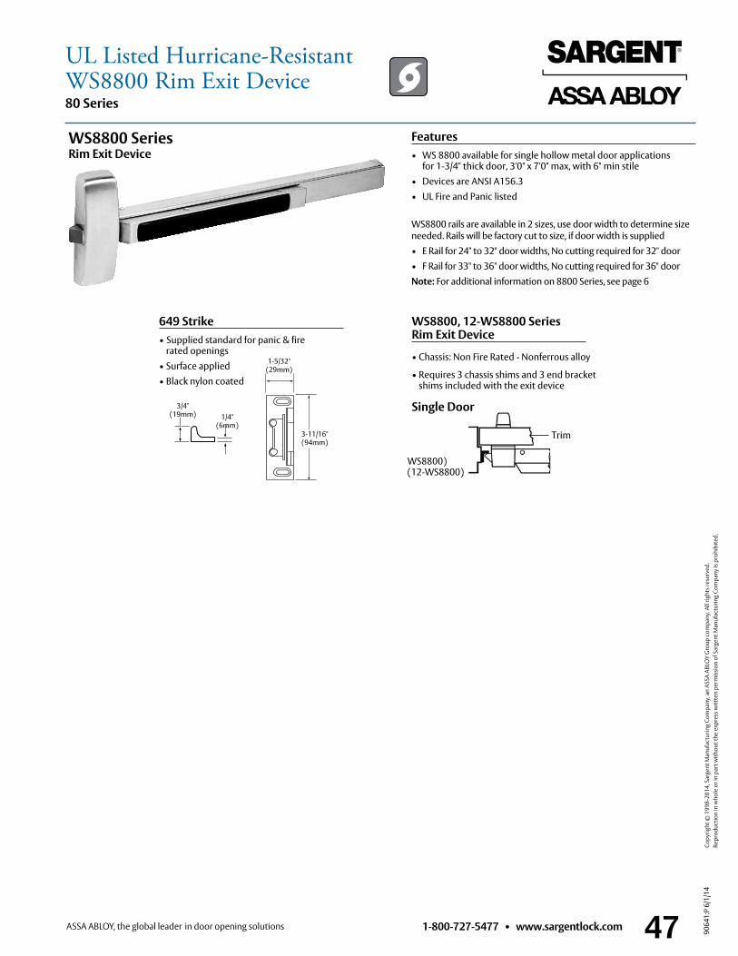
1-800-727-5477 • www.sargentlock.com 47
80 Series
9064
1:P
6/1/
14
Copy
right
© 1
998-
2014
, Sar
gent
Man
ufac
turin
g Co
mpa
ny, a
n AS
SA A
BLO
Y G
roup
com
pany
. All
right
s res
erve
d.
Re
prod
uctio
n in
who
le o
r in
part
with
out t
he e
xpre
ss w
ritte
n pe
rmis
sion
of S
arge
nt M
anuf
actu
ring
Com
pany
is p
rohi
bite
d.
WS8800 rails are available in 2 sizes, use door width to determine size needed . Rails will be factory cut to size, if door width is supplied• E Rail for 24" to 32" door widths, No cutting required for 32" door• F Rail for 33" to 36" door widths, No cutting required for 36" doorNote: For additional information on 8800 Series, see page 6
WS8800 Series Rim Exit Device
WS8800, 12-WS8800 Series Rim Exit Device
649 Strike• Supplied standard for panic & fire
rated openings• Surface applied• Black nylon coated
3/4" (19mm) 1/4"
(6mm)
1-5/32"(29mm)
3-11/16"(94mm)
Features• WS 8800 available for single hollow metal door applications
for 1-3/4" thick door, 3'0" x 7'0" max, with 6" min stile• Devices are ANSI A156 .3• UL Fire and Panic listed
• Chassis: Non Fire Rated - Nonferrous alloy
• Requires 3 chassis shims and 3 end bracket shims included with the exit device
Trim
Single Door
UL Listed Hurricane-ResistantWS8800 Rim Exit Device
WS8800) (12-WS8800)
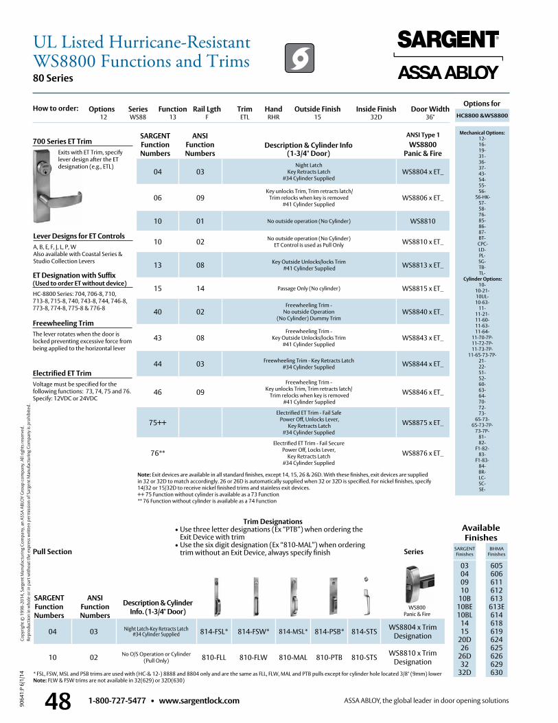
1-800-727-5477 • www.sargentlock.com48
80 Series
9064
1:P
6/1/
14
Copy
right
© 1
998-
2014
, Sar
gent
Man
ufac
turin
g Co
mpa
ny, a
n AS
SA A
BLO
Y G
roup
com
pany
. All
right
s res
erve
d.
Re
prod
uctio
n in
who
le o
r in
part
with
out t
he e
xpre
ss w
ritte
n pe
rmis
sion
of S
arge
nt M
anuf
actu
ring
Com
pany
is p
rohi
bite
d.
04 03Night Latch
Key Retracts Latch #34 Cylinder Supplied
WS8804 x ET_
06 09 Key unlocks Trim, Trim retracts latch/
Trim relocks when key is removed #41 Cylinder Supplied
WS8806 x ET_
10 01 No outside operation (No Cylinder) WS8810
10 02 No outside operation (No Cylinder) ET Control is used as Pull Only WS8810 x ET_
13 08 Key Outside Unlocks/locks Trim #41 Cylinder Supplied WS8813 x ET_
15 14 Passage Only (No cylinder) WS8815 x ET_
40 02Freewheeling Trim -
No outside Operation (No Cylinder) Dummy Trim
WS8840 x ET_
43 08Freewheeling Trim -
Key Outside Unlocks/locks Trim#41 Cylinder Supplied
WS8843 x ET_
44 03 Freewheeling Trim - Key Retracts Latch #34 Cylinder Supplied WS8844 x ET_
46 09Freewheeling Trim -
Key unlocks Trim, Trim retracts latch/ Trim relocks when key is removed
#41 Cylinder Supplied
WS8846 x ET_
75++Electrified ET Trim - Fail Safe
Power Off, Unlocks Lever, Key Retracts Latch
#34 Cylinder Supplied
WS8875 x ET_
76**Electrified ET Trim - Fail Secure
Power Off, Locks Lever, Key Retracts Latch
#34 Cylinder Supplied
WS8876 x ET_
ANSI Type 1
Options for
Description & Cylinder Info (1-3/4" Door)
WS8800Panic & Fire
HC8800 &WS8800
Mechanical Options: 12- 16- 19- 31- 36- 37- 43- 54- 55- 56-
56-HK- 57- 58- 76-85-86-87- BT-
CPC- LD- PL- SG- TB- TL-
Cylinder Options: 10-
10-21- 10UL- 10-63-
11- 11-21- 11-60- 11-63- 11-64-
11-70-7P- 11-72-7P- 11-73-7P-
11-65-73-7P- 21- 22- 51- 52- 60- 63- 64- 70- 72- 73-
65-73- 65-73-7P-
73-7P- 81- 82-
F1-82- 83-
F1-83- 84- BR- LC-SC-SE-
Freewheeling TrimThe lever rotates when the door is locked preventing excessive force from being applied to the horizontal lever
Note: Exit devices are available in all standard finishes, except 14, 15, 26 & 26D . With these finishes, exit devices are supplied in 32 or 32D to match accordingly . 26 or 26D is automatically supplied when 32 or 32D is specified . For nickel finishes, specify 14/32 or 15/32D to receive nickel finished trims and stainless exit devices .++ 75 Function without cylinder is available as a 73 Function** 76 Function without cylinder is available as a 74 Function
Description & Cylinder Info. (1-3/4" Door)
Available Finishes
SARGENT Finishes
BHMA Finishes
03 04 09 10
10B 10BE10BL
1415
20D26
26D32
32D
605 606 611 612 613
613E614618619624625626629630* FSL, FSW, MSL and PSB trims are used with (HC-& 12-) 8888 and 8804 only and are the same as FLL, FLW, MAL and PTB pulls except for cylinder hole located 3/8" (9mm) lower
Note: FLW & FSW trims are not available in 32(629) or 32D(630)
700 Series ET Trim Exits with ET Trim, specify
lever design after the ET designation (e .g ., ETL)
Options Series Function Rail Lgth Trim Hand Outside Finish Inside Finish Door Width 12 WS88 13 F ETL RHR 15 32D 36"
04 03 Night Latch-Key Retracts Latch#34 Cylinder Supplied 814-FSL* 814-FSW* 814-MSL* 814-PSB* 814-STS WS8804 x Trim
Designation
10 02 No O/S Operation or Cylinder(Pull Only) 810-FLL 810-FLW 810-MAL 810-PTB 810-STS WS8810 x Trim
Designation
WS800Panic & Fire
Series
SARGENT Function Numbers
ANSIFunction Numbers
SARGENT Function Numbers
ANSIFunction Numbers
How to order:
Lever Designs for ET ControlsA, B, E, F, J, L, P, WAlso available with Coastal Series &Studio Collection Levers
Electrified ET TrimVoltage must be specified for the following functions: 73, 74, 75 and 76 . Specify: 12VDC or 24VDC
Pull Section
ET Designation with Suffix (Used to order ET without device)HC-8800 Series: 704, 706-8, 710, 713-8, 715-8, 740, 743-8, 744, 746-8, 773-8, 774-8, 775-8 & 776-8
Trim Designations• Use three letter designations (Ex “PTB”) when ordering the
Exit Device with trim• Use the six digit designation (Ex “810-MAL”) when ordering
trim without an Exit Device, always specify finish
UL Listed Hurricane-ResistantWS8800 Functions and Trims
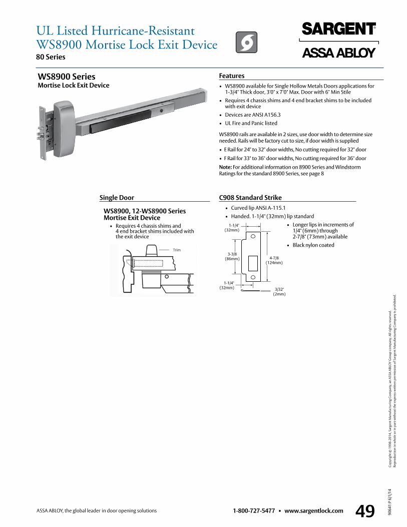
1-800-727-5477 • www.sargentlock.com 49
80 Series
9064
1:P
6/1/
14
Copy
right
© 1
998-
2014
, Sar
gent
Man
ufac
turin
g Co
mpa
ny, a
n AS
SA A
BLO
Y G
roup
com
pany
. All
right
s res
erve
d.
Re
prod
uctio
n in
who
le o
r in
part
with
out t
he e
xpre
ss w
ritte
n pe
rmis
sion
of S
arge
nt M
anuf
actu
ring
Com
pany
is p
rohi
bite
d.
C908 Standard Strike • Curved lip ANSI A-115 .1 • Handed . 1-1/4" (32mm) lip standard • Longer lips in increments of
1/4" (6mm) through 2-7/8" (73mm) available
• Black nylon coated
Single Door
1-1/4" (32mm)
1-1/4"(32mm) 3/32"
(2mm)
3-3/8 (86mm) 4-7/8
(124mm)
WS8900, 12-WS8900 Series Mortise Exit Device • Requires 4 chassis shims and
4 end bracket shims included with the exit device
WS8900 rails are available in 2 sizes, use door width to determine size needed . Rails will be factory cut to size, if door width is supplied
• E Rail for 24" to 32" door widths, No cutting required for 32" door
• F Rail for 33" to 36" door widths, No cutting required for 36" door
Note: For additional information on 8900 Series and Windstorm Ratings for the standard 8900 Series, see page 8
WS8900 Series Mortise Lock Exit Device
Features• WS8900 available for Single Hollow Metals Doors applications for
1-3/4" Thick door, 3'0" x 7'0" Max . Door with 6" Min Stile• Requires 4 chassis shims and 4 end bracket shims to be included
with exit device• Devices are ANSI A156 .3 • UL Fire and Panic listed
UL Listed Hurricane-ResistantWS8900 Mortise Lock Exit Device
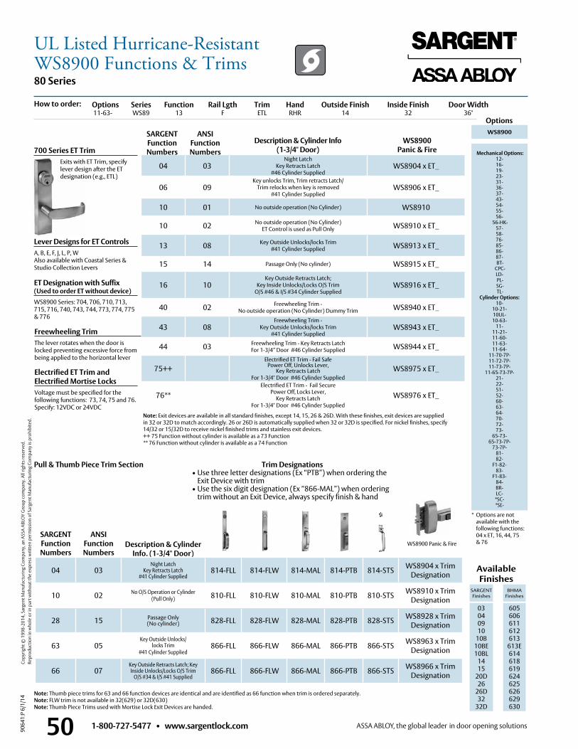
1-800-727-5477 • www.sargentlock.com50
80 Series
9064
1:P
6/1/
14
Copy
right
© 1
998-
2014
, Sar
gent
Man
ufac
turin
g Co
mpa
ny, a
n AS
SA A
BLO
Y G
roup
com
pany
. All
right
s res
erve
d.
Re
prod
uctio
n in
who
le o
r in
part
with
out t
he e
xpre
ss w
ritte
n pe
rmis
sion
of S
arge
nt M
anuf
actu
ring
Com
pany
is p
rohi
bite
d.
WS8900 Panic & Fire
Options
Description & Cylinder Info (1-3/4" Door)
WS8900Panic & Fire
WS8900
Mechanical Options: 12- 16- 19- 23- 31- 36- 37- 43- 54- 55- 56-
56-HK- 57- 58- 76-85-86-87- BT-
CPC- LD- PL- SG- TL-
Cylinder Options: 10-
10-21- 10UL- 10-63-
11- 11-21- 11-60- 11-63- 11-64-
11-70-7P- 11-72-7P- 11-73-7P-
11-65-73-7P- 21- 22- 51- 52- 60- 63- 64- 70- 72- 73-
65-73- 65-73-7P-
73-7P- 81- 82-
F1-82- 83-
F1-83- 84- BR- LC-
*SC- *SE-
Lever Designs for ET ControlsA, B, E, F, J, L, P, WAlso available with Coastal Series &Studio Collection Levers
Description & Cylinder Info. (1-3/4" Door)
Available Finishes
SARGENT Finishes
BHMA Finishes
03 04 09 10
10B 10BE10BL
1415
20D26
26D32
32D
605 606 611 612 613
613E614618619624625626629 630
700 Series ET Trim Exits with ET Trim, specify
lever design after the ET designation (e .g ., ETL)
Options Series Function Rail Lgth Trim Hand Outside Finish Inside Finish Door Width 11-63- WS89 13 F ETL RHR 14 32 36"
04 03Night Latch
Key Retracts Latch #46 Cylinder Supplied
WS8904 x ET_
06 09Key unlocks Trim, Trim retracts Latch/
Trim relocks when key is removed#41 Cylinder Supplied
WS8906 x ET_
10 01 No outside operation (No Cylinder) WS8910
10 02 No outside operation (No Cylinder) ET Control is used as Pull Only WS8910 x ET_
13 08 Key Outside Unlocks/locks Trim #41 Cylinder Supplied WS8913 x ET_
15 14 Passage Only (No cylinder) WS8915 x ET_
16 10Key Outside Retracts Latch;
Key Inside Unlocks/Locks O/S Trim O/S #46 & I/S #34 Cylinder Supplied
WS8916 x ET_
40 02 Freewheeling Trim - No outside operation (No Cylinder) Dummy Trim WS8940 x ET_
43 08Freewheeling Trim -
Key Outside Unlocks/locks Trim #41 Cylinder Supplied
WS8943 x ET_
44 03 Freewheeling Trim - Key Retracts Latch For 1-3/4” Door #46 Cylinder Supplied WS8944 x ET_
75++Electrified ET Trim - Fail Safe
Power Off, Unlocks Lever, Key Retracts Latch
For 1-3/4" Door #46 Cylinder SuppliedWS8975 x ET_
76**Electrified ET Trim - Fail Secure
Power Off, Locks Lever, Key Retracts Latch
For 1-3/4" Door #46 Cylinder Supplied
WS8976 x ET_
04 03Night Latch
Key Retracts Latch #41 Cylinder Supplied
814-FLL 814-FLW 814-MAL 814-PTB 814-STS WS8904 x TrimDesignation
10 02 No O/S Operation or Cylinder (Pull Only) 810-FLL 810-FLW 810-MAL 810-PTB 810-STS WS8910 x Trim
Designation
28 15 Passage Only (No cylinder) 828-FLL 828-FLW 828-MAL 828-PTB 828-STS WS8928 x Trim
Designation
63 05Key Outside Unlocks/
locks Trim #41 Cylinder Supplied
866-FLL 866-FLW 866-MAL 866-PTB 866-STS WS8963 x TrimDesignation
66 07Key Outside Retracts Latch; Key Inside Unlocks/Locks O/S Trim
O/S #34 & I/S #41 Supplied866-FLL 866-FLW 866-MAL 866-PTB 866-STS WS8966 x Trim
Designation
Note: Exit devices are available in all standard finishes, except 14, 15, 26 & 26D . With these finishes, exit devices are supplied in 32 or 32D to match accordingly . 26 or 26D is automatically supplied when 32 or 32D is specified . For nickel finishes, specify 14/32 or 15/32D to receive nickel finished trims and stainless exit devices .++ 75 Function without cylinder is available as a 73 Function** 76 Function without cylinder is available as a 74 Function
* Options are not available with the following functions: 04 x ET, 16, 44, 75 & 76
SARGENT Function Numbers
ANSIFunction Numbers
Pull & Thumb Piece Trim Section
SARGENT Function Numbers
ANSIFunction Numbers
How to order:
Freewheeling TrimThe lever rotates when the door is locked preventing excessive force from being applied to the horizontal lever
Electrified ET Trim and Electrified Mortise Locks Voltage must be specified for the following functions: 73, 74, 75 and 76 . Specify: 12VDC or 24VDC
ET Designation with Suffix (Used to order ET without device)WS8900 Series: 704, 706, 710, 713, 715, 716, 740, 743, 744, 773, 774, 775 & 776
Trim Designations• Use three letter designations (Ex “PTB”) when ordering the
Exit Device with trim• Use the six digit designation (Ex “866-MAL”) when ordering
trim without an Exit Device, always specify finish & hand
Note: Thumb piece trims for 63 and 66 function devices are identical and are identified as 66 function when trim is ordered separately .Note: FLW trim is not available in 32(629) or 32D(630) Note: Thumb Piece Trims used with Mortise Lock Exit Devices are handed .
UL Listed Hurricane-ResistantWS8900 Functions & Trims
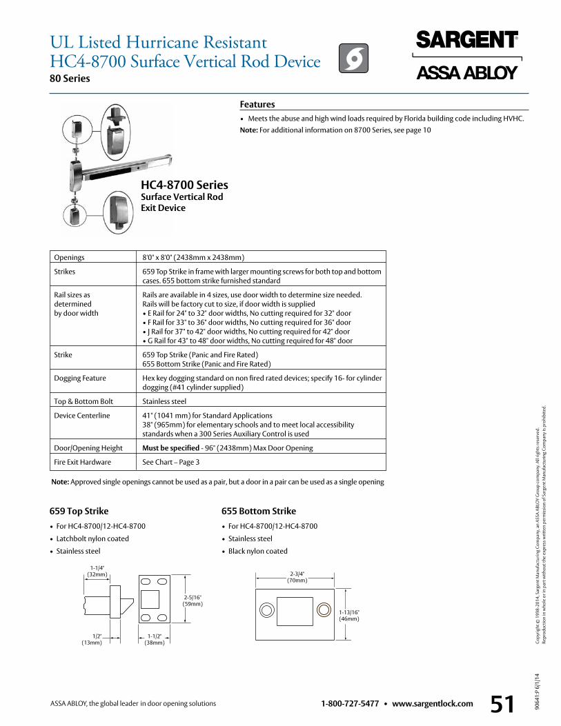
1-800-727-5477 • www.sargentlock.com 51
80 Series
9064
1:P
6/1/
14
Copy
right
© 1
998-
2014
, Sar
gent
Man
ufac
turin
g Co
mpa
ny, a
n AS
SA A
BLO
Y G
roup
com
pany
. All
right
s res
erve
d.
Re
prod
uctio
n in
who
le o
r in
part
with
out t
he e
xpre
ss w
ritte
n pe
rmis
sion
of S
arge
nt M
anuf
actu
ring
Com
pany
is p
rohi
bite
d.
655 Bottom Strike• For HC4-8700/12-HC4-8700
• Stainless steel
• Black nylon coated
659 Top Strike• For HC4-8700/12-HC4-8700
• Latchbolt nylon coated
• Stainless steel
Openings 8'0" x 8'0" (2438mm x 2438mm)
Strikes 659 Top Strike in frame with larger mounting screws for both top and bottom cases . 655 bottom strike furnished standard
Rail sizes as Rails are available in 4 sizes, use door width to determine size needed . determined Rails will be factory cut to size, if door width is supplied by door width • E Rail for 24" to 32" door widths, No cutting required for 32" door • F Rail for 33" to 36" door widths, No cutting required for 36" door • J Rail for 37" to 42" door widths, No cutting required for 42" door • G Rail for 43" to 48" door widths, No cutting required for 48" door
Strike 659 Top Strike (Panic and Fire Rated) 655 Bottom Strike (Panic and Fire Rated)
Dogging Feature Hex key dogging standard on non fired rated devices; specify 16- for cylinder dogging (#41 cylinder supplied)
Top & Bottom Bolt Stainless steel
Device Centerline 41" (1041 mm) for Standard Applications 38" (965mm) for elementary schools and to meet local accessibility standards when a 300 Series Auxiliary Control is used
Door/Opening Height Must be specified - 96" (2438mm) Max Door Opening
Fire Exit Hardware See Chart – Page 3
1-1/2" (38mm)
1/2" (13mm)
1-1/4" (32mm)
2-5/16" (59mm)
2-3/4" (70mm)
1-13/16"(46mm)
HC4-8700 Series Surface Vertical Rod Exit Device
Note: Approved single openings cannot be used as a pair, but a door in a pair can be used as a single opening
Features• Meets the abuse and high wind loads required by Florida building code including HVHC .Note: For additional information on 8700 Series, see page 10
UL Listed Hurricane ResistantHC4-8700 Surface Vertical Rod Device
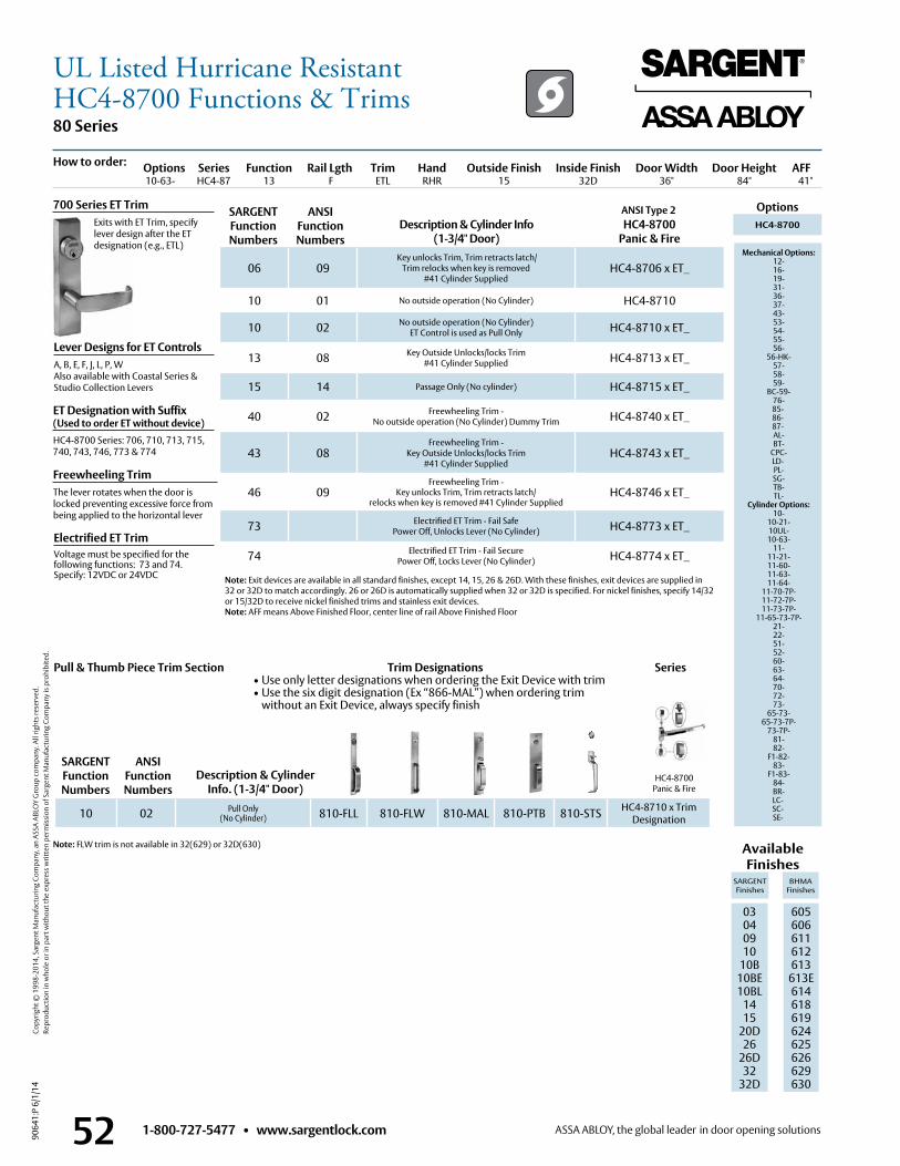
1-800-727-5477 • www.sargentlock.com52
80 Series
9064
1:P
6/1/
14
Copy
right
© 1
998-
2014
, Sar
gent
Man
ufac
turin
g Co
mpa
ny, a
n AS
SA A
BLO
Y G
roup
com
pany
. All
right
s res
erve
d.
Re
prod
uctio
n in
who
le o
r in
part
with
out t
he e
xpre
ss w
ritte
n pe
rmis
sion
of S
arge
nt M
anuf
actu
ring
Com
pany
is p
rohi
bite
d.
HC4-8700Panic & Fire
ANSI Type 2 OptionsDescription & Cylinder Info
(1-3/4" Door)HC4-8700
Panic & FireHC4-8700
Mechanical Options: 12- 16- 19- 31- 36- 37- 43- 53- 54- 55- 56-
56-HK- 57- 58- 59-
BC-59- 76-85-86-87- AL- BT-
CPC- LD- PL- SG- TB- TL-
Cylinder Options: 10-
10-21- 10UL- 10-63-
11- 11-21- 11-60- 11-63- 11-64-
11-70-7P- 11-72-7P- 11-73-7P-
11-65-73-7P- 21- 22- 51- 52- 60- 63- 64- 70- 72- 73-
65-73- 65-73-7P-
73-7P- 81- 82-
F1-82- 83-
F1-83- 84- BR- LC-SC-SE-
Lever Designs for ET ControlsA, B, E, F, J, L, P, WAlso available with Coastal Series &Studio Collection Levers
Freewheeling TrimThe lever rotates when the door is locked preventing excessive force from being applied to the horizontal lever
Electrified ET TrimVoltage must be specified for the following functions: 73 and 74 . Specify: 12VDC or 24VDC
Description & Cylinder Info. (1-3/4" Door)
Available Finishes
SARGENT Finishes
BHMA Finishes
03 04 09 10
10B 10BE10BL
1415
20D26
26D32
32D
605 606 611 612 613
613E614618619624625626629 630
700 Series ET Trim Exits with ET Trim, specify
lever design after the ET designation (e .g ., ETL)
Options Series Function Rail Lgth Trim Hand Outside Finish Inside Finish Door Width Door Height AFF 10-63- HC4-87 13 F ETL RHR 15 32D 36" 84" 41"
06 09 Key unlocks Trim, Trim retracts latch/
Trim relocks when key is removed #41 Cylinder Supplied
HC4-8706 x ET_
10 01 No outside operation (No Cylinder) HC4-8710
10 02 No outside operation (No Cylinder) ET Control is used as Pull Only HC4-8710 x ET_
13 08 Key Outside Unlocks/locks Trim #41 Cylinder Supplied HC4-8713 x ET_
15 14 Passage Only (No cylinder) HC4-8715 x ET_
40 02 Freewheeling Trim - No outside operation (No Cylinder) Dummy Trim HC4-8740 x ET_
43 08Freewheeling Trim -
Key Outside Unlocks/locks Trim#41 Cylinder Supplied
HC4-8743 x ET_
46 09Freewheeling Trim -
Key unlocks Trim, Trim retracts latch/relocks when key is removed #41 Cylinder Supplied
HC4-8746 x ET_
73 Electrified ET Trim - Fail SafePower Off, Unlocks Lever (No Cylinder) HC4-8773 x ET_
74 Electrified ET Trim - Fail SecurePower Off, Locks Lever (No Cylinder) HC4-8774 x ET_
10 02 Pull Only(No Cylinder) 810-FLL 810-FLW 810-MAL 810-PTB 810-STS HC4-8710 x Trim
Designation
SARGENT Function Numbers
ANSIFunction Numbers
SARGENT Function Numbers
ANSIFunction Numbers
Series
How to order:
Note: Exit devices are available in all standard finishes, except 14, 15, 26 & 26D . With these finishes, exit devices are supplied in 32 or 32D to match accordingly . 26 or 26D is automatically supplied when 32 or 32D is specified . For nickel finishes, specify 14/32 or 15/32D to receive nickel finished trims and stainless exit devices . Note: AFF means Above Finished Floor, center line of rail Above Finished Floor
Note: FLW trim is not available in 32(629) or 32D(630)
Pull & Thumb Piece Trim Section
ET Designation with Suffix (Used to order ET without device)HC4-8700 Series: 706, 710, 713, 715, 740, 743, 746, 773 & 774
Trim Designations• Use only letter designations when ordering the Exit Device with trim• Use the six digit designation (Ex “866-MAL”) when ordering trim
without an Exit Device, always specify finish
UL Listed Hurricane ResistantHC4-8700 Functions & Trims
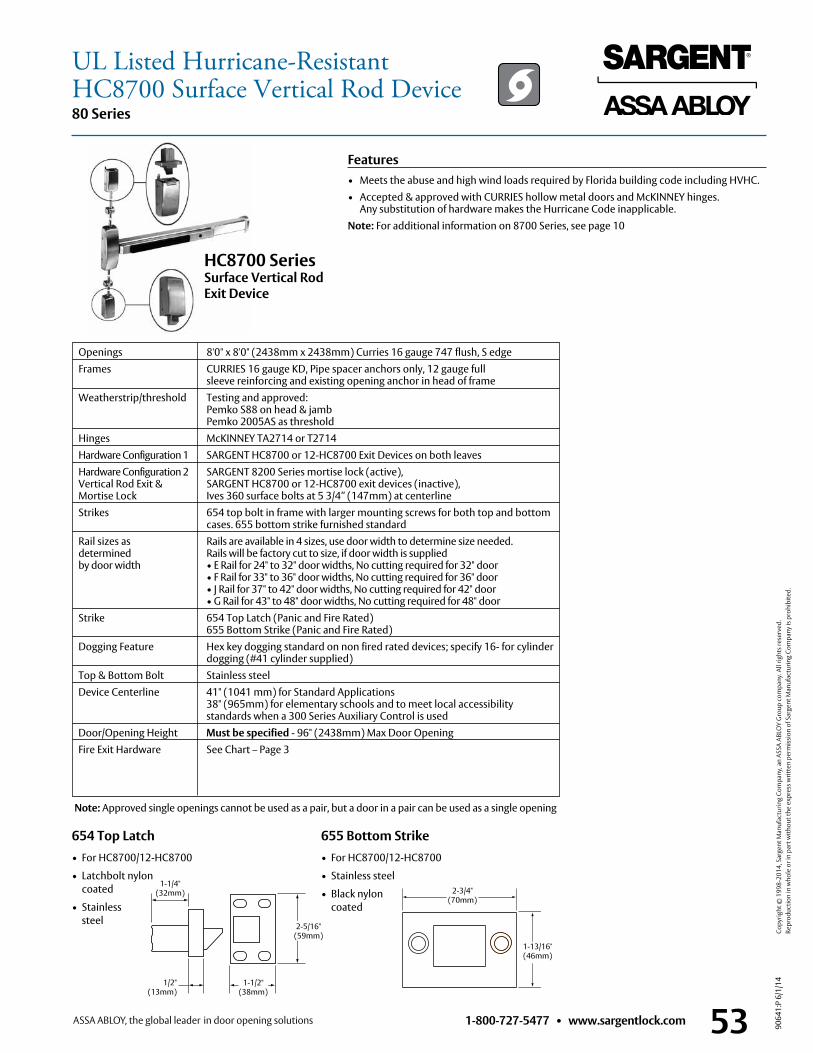
1-800-727-5477 • www.sargentlock.com 53
80 Series
9064
1:P
6/1/
14
Copy
right
© 1
998-
2014
, Sar
gent
Man
ufac
turin
g Co
mpa
ny, a
n AS
SA A
BLO
Y G
roup
com
pany
. All
right
s res
erve
d.
Re
prod
uctio
n in
who
le o
r in
part
with
out t
he e
xpre
ss w
ritte
n pe
rmis
sion
of S
arge
nt M
anuf
actu
ring
Com
pany
is p
rohi
bite
d.
Features• Meets the abuse and high wind loads required by Florida building code including HVHC .• Accepted & approved with CURRIES hollow metal doors and McKINNEY hinges .
Any substitution of hardware makes the Hurricane Code inapplicable .Note: For additional information on 8700 Series, see page 10
655 Bottom Strike• For HC8700/12-HC8700
• Stainless steel
• Black nylon coated
654 Top Latch• For HC8700/12-HC8700
• Latchbolt nylon coated
• Stainless steel
Openings 8'0" x 8'0" (2438mm x 2438mm) Curries 16 gauge 747 flush, S edge Frames CURRIES 16 gauge KD, Pipe spacer anchors only, 12 gauge full
sleeve reinforcing and existing opening anchor in head of frame Weatherstrip/threshold Testing and approved:
Pemko S88 on head & jamb Pemko 2005AS as threshold
Hinges McKINNEY TA2714 or T2714 Hardware Configuration 1 SARGENT HC8700 or 12-HC8700 Exit Devices on both leaves Hardware Configuration 2 SARGENT 8200 Series mortise lock (active), Vertical Rod Exit & SARGENT HC8700 or 12-HC8700 exit devices (inactive), Mortise Lock Ives 360 surface bolts at 5 3/4” (147mm) at centerline Strikes 654 top bolt in frame with larger mounting screws for both top and bottom
cases . 655 bottom strike furnished standard Rail sizes as Rails are available in 4 sizes, use door width to determine size needed . determined Rails will be factory cut to size, if door width is supplied by door width • E Rail for 24" to 32" door widths, No cutting required for 32" door • F Rail for 33" to 36" door widths, No cutting required for 36" door • J Rail for 37" to 42" door widths, No cutting required for 42" door • G Rail for 43" to 48" door widths, No cutting required for 48" door Strike 654 Top Latch (Panic and Fire Rated)
655 Bottom Strike (Panic and Fire Rated) Dogging Feature Hex key dogging standard on non fired rated devices; specify 16- for cylinder dogging (#41 cylinder supplied) Top & Bottom Bolt Stainless steel Device Centerline 41" (1041 mm) for Standard Applications 38" (965mm) for elementary schools and to meet local accessibility standards when a 300 Series Auxiliary Control is used Door/Opening Height Must be specified - 96" (2438mm) Max Door Opening Fire Exit Hardware See Chart – Page 3
1-1/2" (38mm)
1/2" (13mm)
1-1/4" (32mm)
2-5/16" (59mm)
2-3/4" (70mm)
1-13/16"(46mm)
HC8700 Series Surface Vertical Rod Exit Device
Note: Approved single openings cannot be used as a pair, but a door in a pair can be used as a single opening
UL Listed Hurricane-ResistantHC8700 Surface Vertical Rod Device
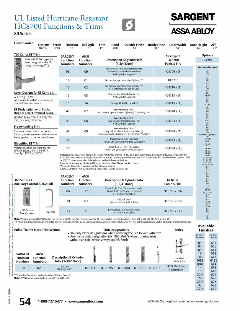
1-800-727-5477 • www.sargentlock.com54
80 Series
9064
1:P
6/1/
14
Copy
right
© 1
998-
2014
, Sar
gent
Man
ufac
turin
g Co
mpa
ny, a
n AS
SA A
BLO
Y G
roup
com
pany
. All
right
s res
erve
d.
Re
prod
uctio
n in
who
le o
r in
part
with
out t
he e
xpre
ss w
ritte
n pe
rmis
sion
of S
arge
nt M
anuf
actu
ring
Com
pany
is p
rohi
bite
d.
HC8700Panic & Fire
ANSI Type 2 OptionsDescription & Cylinder Info
(1-3/4" Door)HC8700
Panic & FireHC8700
Mechanical Options: 12- 16- 19- 31- 36- 37- 43- 53- 54- 55- 56-
56-HK- 57- 58- 59-
BC-59- 76-85-86-87- AL- BT-
CPC- LD- PL- SG- TB- TL-
Cylinder Options: 10-
10-21- 10UL- 10-63-
11- 11-21- 11-60- 11-63- 11-64-
11-70-7P- 11-72-7P- 11-73-7P-
11-65-73-7P- 21- 22- 51- 52- 60- 63- 64- 70- 72- 73-
65-73- 65-73-7P-
73-7P- 81- 82-
F1-82- 83-
F1-83- 84- BR- LC-SC-SE-
Lever Designs for ET ControlsA, B, E, F, J, L, P, WAlso available with Coastal Series &Studio Collection Levers
Freewheeling TrimThe lever rotates when the door is locked preventing excessive force from being applied to the horizontal lever
Electrified ET TrimVoltage must be specified for the following functions: 73 and 74 . Specify: 12VDC or 24VDC
Description & Cylinder Info. (1-3/4” Door)
Available Finishes
SARGENT Finishes
BHMA Finishes
03 04 09 10
10B 10BE10BL
1415
20D26
26D32
32D
605 606 611 612 613
613E614618619624625626629 630
700 Series ET Trim Exits with ET Trim, specify
lever design after the ET designation (e .g ., ETL)
Options Series Function Rail Lgth Trim Hand Outside Finish Inside Finish Door Width Door Height AFF 10-63- HC87 13 F ETL RHR 15 32D 36" 84" 41"
06 09 Key unlocks Trim, Trim retracts latch/
Trim relocks when key is removed #41 Cylinder Supplied
HC8706 x ET_
10 01 No outside operation (No Cylinder)** HC8710
10 02 No outside operation (No Cylinder)** ET Control is used as Pull Only HC8710 x ET_
13 08 Key Outside Unlocks/locks Trim #41 Cylinder Supplied HC8713 x ET_
15 14 Passage Only (No cylinder) HC8715 x ET_
40 02 Freewheeling Trim - No outside operation (No Cylinder)** Dummy Trim HC8740 x ET_
43 08Freewheeling Trim -
Key Outside Unlocks/locks Trim#41 Cylinder Supplied
HC8743 x ET_
46 09Freewheeling Trim -
Key unlocks Trim, Trim retracts latch/relocks when key is removed #41 Cylinder Supplied
HC8746 x ET_
73 Electrified ET Trim - Fail SafePower Off, Unlocks Lever (No Cylinder)** HC8773 x ET_
74 Electrified ET Trim - Fail SecurePower Off, Locks Lever (No Cylinder)** HC8774 x ET_
10 02 Pull Only(No Cylinder)*** 810-FLL 810-FLW 810-MAL 810-PTB 810-STS HC8710 x Trim
Designation
06 12Key unlocks Turn, Turn retracts latch/
Turn relocks when key is removed#41 Cylinder Supplied
HC8710 x 306
10 02 862 Pull Only(Optional Pulls: 863 & 864) HC8710 x 862
13 11 Key Outside Unlocks/locks Turn#41 Cylinder Supplied HC8710 x 313862 Pull
SARGENT Function Numbers
ANSIFunction Numbers
SARGENT Function Numbers
Description & Cylinder Info(1-3/4" Door)
300 Series++ Auxiliary Control & 862 Pull
ANSIFunction Numbers
HC8700 Panic & Fire
SARGENT Function Numbers
ANSIFunction Numbers
300 Series Aux . Control
Series
How to order:
Note: Exit devices are available in all standard finishes, except 14, 15, 26 & 26D . With these finishes, exit devices are supplied in 32 or 32D to match accordingly . 26 or 26D is automatically supplied when 32 or 32D is specified . For nickel finishes, specify 14/32 or 15/32D to receive nickel finished trims and stainless exit devices . Note: AFF means Above Finished Floor, center line of rail Above Finished Floor** Cylinder Override is available with a 306 Aux ControlExample Order: 8773F 12V x ETMG x 306 x RHR x 32D x 36"w x 84"h
*** Cylinder Override is available with a 306 Aux ControlNote: FLW trim is not available in 32(629) or 32D(630)
Pull & Thumb Piece Trim Section
ET Designation with Suffix (Used to order ET without device)HC8700 Series: 706, 710, 713, 715, 740, 743, 746, 773 & 774
Note: When ordering HC8700 Series Exit Device x 300 Series Aux . Control, specify 10 Function for the exit . Example: HC8710F x 306 x RHR x 32D x 42" x 90" ++ Note: Exit Devices must be mounted 38” AFF when used with a 300 Series Auxiliary Controls to meet ICC/ANSI A117 .1-2003 Accessible & Usable Buildings and Facilities Code
Trim Designations• Use only letter designations when ordering the Exit Device with trim• Use the six digit designation (Ex “866-MAL”) when ordering trim
without an Exit Device, always specify finish
UL Listed Hurricane-ResistantHC8700 Functions & Trims
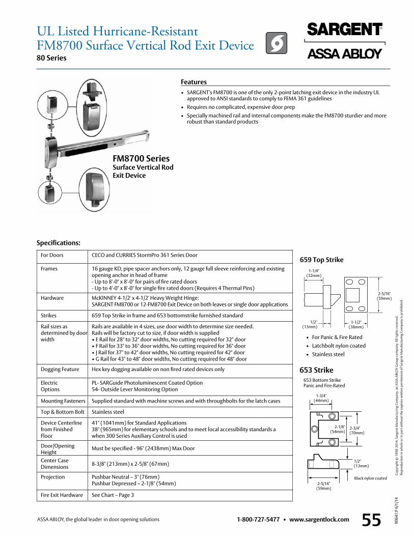
1-800-727-5477 • www.sargentlock.com 55
80 Series
9064
1:P
6/1/
14
Copy
right
© 1
998-
2014
, Sar
gent
Man
ufac
turin
g Co
mpa
ny, a
n AS
SA A
BLO
Y G
roup
com
pany
. All
right
s res
erve
d.
Re
prod
uctio
n in
who
le o
r in
part
with
out t
he e
xpre
ss w
ritte
n pe
rmis
sion
of S
arge
nt M
anuf
actu
ring
Com
pany
is p
rohi
bite
d.
Specifications:
659 Top Strike
• For Panic & Fire Rated • Latchbolt nylon coated • Stainless steel
FM8700 Series Surface Vertical Rod Exit Device
1-1/2" (38mm)
1/2" (13mm)
1-1/4" (32mm)
2-5/16" (59mm)
Features• SARGENT’s FM8700 is one of the only 2-point latching exit device in the industry UL
approved to ANSI standards to comply to FEMA 361 guidelines• Requires no complicated, expensive door prep• Specially machined rail and internal components make the FM8700 sturdier and more
robust than standard products
653 Bottom StrikePanic and Fire-Rated
653 Strike
1/2" (13mm)
2-5/16" (59mm)
1-3/4" (44mm)
2-3/4" (70mm)
2-1/8" (54mm)
Black nylon coated
For Doors CECO and CURRIES StormPro 361 Series Door
Frames 16 gauge KD, pipe spacer anchors only, 12 gauge full sleeve reinforcing and existing opening anchor in head of frame - Up to 8'-0" x 8'-0" for pairs of fire rated doors- Up to 4'-0" x 8'-0" for single fire rated doors (Requires 4 Thermal Pins)
Hardware McKINNEY 4-1/2' x 4-1/2' Heavy Weight Hinge: SARGENT FM8700 or 12-FM8700 Exit Device on both leaves or single door applications
Strikes 659 Top Strike in frame and 653 bottomstrike furnished standard
Rail sizes as determined by door width
Rails are available in 4 sizes, use door width to determine size needed .Rails will be factory cut to size, if door width is supplied • E Rail for 28" to 32" door widths, No cutting required for 32" door• F Rail for 33" to 36" door widths, No cutting required for 36" door• J Rail for 37" to 42" door widths, No cutting required for 42" door• G Rail for 43" to 48" door widths, No cutting required for 48" door
Dogging Feature Hex key dogging available on non fired rated devices only
Electric Options
PL- SARGuide Photoluminescent Coated Option54- Outside Lever Monitoring Option
Mounting Fasteners Supplied standard with machine screws and with throughbolts for the latch cases
Top & Bottom Bolt Stainless steel
Device Centerlinefrom Finished Floor
41" (1041mm) for Standard Applications38" (965mm) for elementary schools and to meet local accessibility standards a when 300 Series Auxiliary Control is used
Door/Opening Height
Must be specified - 96" (2438mm) Max Door
Center Case Dimensions 8-3/8" (213mm) x 2-5/8" (67mm)
Projection Pushbar Neutral – 3" (76mm)Pushbar Depressed – 2-1/8" (54mm)
Fire Exit Hardware See Chart – Page 3
UL Listed Hurricane-ResistantFM8700 Surface Vertical Rod Exit Device
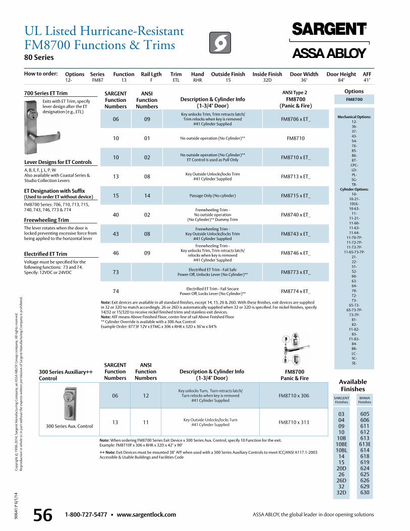
1-800-727-5477 • www.sargentlock.com56
80 Series
9064
1:P
6/1/
14
Copy
right
© 1
998-
2014
, Sar
gent
Man
ufac
turin
g Co
mpa
ny, a
n AS
SA A
BLO
Y G
roup
com
pany
. All
right
s res
erve
d.
Re
prod
uctio
n in
who
le o
r in
part
with
out t
he e
xpre
ss w
ritte
n pe
rmis
sion
of S
arge
nt M
anuf
actu
ring
Com
pany
is p
rohi
bite
d.
ANSI Type 2 OptionsDescription & Cylinder Info
(1-3/4" Door)FM8700
(Panic & Fire)FM8700
Mechanical Options: 12- 36- 37- 43-54- 76-85-86-87-
CPC- LD- PL- SG- TB-
Cylinder Options: 10-
10-21- 10UL- 10-63-
11- 11-21- 11-60- 11-63- 11-64-
11-70-7P- 11-72-7P- 11-73-7P-
11-65-73-7P- 21- 22- 51- 52- 60- 63- 64- 70- 72- 73-
65-73- 65-73-7P-
73-7P- 81- 82-
F1-82- 83-
F1-83- 84- BR- LC-SC-SE-
Lever Designs for ET ControlsA, B, E, F, J, L, P, WAlso available with Coastal Series & Studio Collection Levers
Freewheeling TrimThe lever rotates when the door is locked preventing excessive force from being applied to the horizontal lever
Available Finishes
SARGENT Finishes
BHMA Finishes
03 04 09 10
10B10BE 10BL
1415
20D26
26D32
32D
605 606 611 612 613
613E 614618619624625626629 630
700 Series ET Trim Exits with ET Trim, specify
lever design after the ET designation (e .g ., ETL)
Options Series Function Rail Lgth Trim Hand Outside Finish Inside Finish Door Width Door Height AFF12- FM87 13 F ETL RHR 15 32D 36" 84" 41"
06 09 Key unlocks Trim, Trim retracts latch/
Trim relocks when key is removed #41 Cylinder Supplied
FM8706 x ET_
10 01 No outside operation (No Cylinder)** FM8710
10 02 No outside operation (No Cylinder)** ET Control is used as Pull Only FM8710 x ET_
13 08 Key Outside Unlocks/locks Trim #41 Cylinder Supplied FM8713 x ET_
15 14 Passage Only (No cylinder) FM8715 x ET_
40 02Freewheeling Trim -
No outside operation (No Cylinder)** Dummy Trim
FM8740 x ET_
43 08Freewheeling Trim -
Key Outside Unlocks/locks Trim#41 Cylinder Supplied
FM8743 x ET_
46 09Freewheeling Trim -
Key unlocks Trim, Trim retracts latch/relocks when key is removed
#41 Cylinder Supplied
FM8746 x ET_
73 Electrified ET Trim - Fail SafePower Off, Unlocks Lever (No Cylinder)** FM8773 x ET_
74 Electrified ET Trim - Fail SecurePower Off, Locks Lever (No Cylinder)** FM8774 x ET_
Note: When ordering FM8700 Series Exit Device x 300 Series Aux . Control, specify 10 Function for the exit . Example: FM8710F x 306 x RHR x 32D x 42" x 90"
++ Note: Exit Devices must be mounted 38" AFF when used with a 300 Series Auxiliary Controls to meet ICC/ANSI A117 .1-2003 Accessible & Usable Buildings and Facilities Code
FM8700Panic & Fire
SARGENT Function Numbers
ANSIFunction Numbers
How to order:
06 12Key unlocks Turn, Turn retracts latch/
Turn relocks when key is removed#41 Cylinder Supplied
FM8710 x 306
13 11 Key Outside Unlocks/locks Turn#41 Cylinder Supplied FM8710 x 313
SARGENT Function Numbers
Description & Cylinder Info(1-3/4" Door)
300 Series Auxiliary++Control
ANSIFunction Numbers
300 Series Aux . Control
Note: Exit devices are available in all standard finishes, except 14, 15, 26 & 26D . With these finishes, exit devices are supplied in 32 or 32D to match accordingly . 26 or 26D is automatically supplied when 32 or 32D is specified . For nickel finishes, specify 14/32 or 15/32D to receive nickel finished trims and stainless exit devices .Note: AFF means Above Finished Floor, center line of rail Above Finished Floor** Cylinder Override is available with a 306 Aux ControlExample Order: 8773F 12V x ETMG x 306 x RHR x 32D x 36"w x 84"h
Electrified ET TrimVoltage must be specified for the following functions: 73 and 74 . Specify: 12VDC or 24VDC
ET Designation with Suffix (Used to order ET without device)FM8700 Series: 706, 710, 713, 715, 740, 743, 746, 773 & 774
UL Listed Hurricane-ResistantFM8700 Functions & Trims
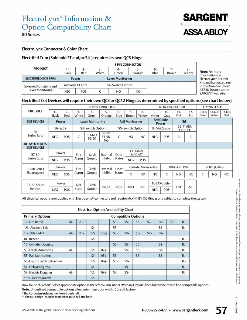
1-800-727-5477 • www.sargentlock.com 57
80 Series
9064
1:P
6/1/
14
Copy
right
© 1
998-
2014
, Sar
gent
Man
ufac
turin
g Co
mpa
ny, a
n AS
SA A
BLO
Y G
roup
com
pany
. All
right
s res
erve
d.
Re
prod
uctio
n in
who
le o
r in
part
with
out t
he e
xpre
ss w
ritte
n pe
rmis
sion
of S
arge
nt M
anuf
actu
ring
Com
pany
is p
rohi
bite
d.
Electrical Option Availability Chart
Primary Options Compatible Options12- Fire Rated AL- BT- 53- 55- 56- 57- 58- 59- TL-
*AL- Alarmed Exit 12- 53- 58- TL-
TL- SARGuide® AL- BT- 12- 16-‡ 53- 55- 56- 57- 58-
BT- Beacon 12- TL-
16- Cylinder Dogging 53- 55- 56- 58- TL-
53- Latch Monitoring AL- 12- 16-‡- 55- 56- 58- TL-
55- Rail Monitoring 12- 16-‡- 53- 56- 58- TL-
56- Electric Latch Retraction 12- 16-‡- 53- 55- TL-
57- Delayed Egress 12- 55- TL-
58- Electric Dogging AL- 12- 16-‡- 53- 55- TL-
**59- Electroguard® 12-
PRODUCT8 PIN CONNECTOR
1- Black
2- Red
3- White
4- Green
5- Orange
6- Blue
7- Brown
8- Yellow
ELECTRIFIED EXIT TRIM Power Lever Monitoring
Solenoid Functions and Lever Monitoring
solenoid ET Trim 54- Switch Option
NEG POS C NO NC
All electrical options are supplied with ElectroLynx® connectors and require McKINNEY QC Hinges and cables to complete the system
ElectroLynx Connector & Color Chart
Electrifed Trim (Solenoid ET and/or 54-) requires its own QC8 Hinge
EXIT DEVICES Power Latch Monitoring Rail Monitoring SARGuide Power 56-
80 Series Exits
56- & 58- 53- Switch Option 55- Switch Option TL- SARGuide 56- TIMER CIRCUIT
NEG POS C 53-NO 56-EG
53-NC 53-56-
NOC NO NC NEG POS A B
DELAYED EGRESS EXIT DEVICES
57-80 Series Exits
Power Fire Alarm
EarthGround
External Inhibit
Door Status
EXTERNAL MAGNET
NEG POS NEG POS
59-80 Series Electroguard
Power Fire Alarm
EarthGround
External Inhibit
Door Status
Remote Alarm Relay LBM - OPTION VOICE/GANG
NEG POS C NO NC C NO NC C NO NC
Electrified Exit Devices will require their own QC8 or QC12 Hinge as determined by specified options (see chart below)
PRODUCT 8 PIN CONNECTOR 4 PIN CONNECTOR FLYING LEADS
1- Black
2- Red
3- White
4- Green
5- Orange
6- Blue
7- Brown
8- Yellow
9- Violet
10- Gray
11- Pink
12- Tan
How to use this chart: Select appropriate option in the left column, under “Primary Option”, then follow the row to find compatible options .Note: Underlined compatible options affect minimum door width . Consult factory .* The AL- design includes monitored push rail ** The 59- design includes monitored push rail and latch
13-Red/Green
14-Red/Yellow
14-Red/Black
Note: For more information on ElectroLynx® Retrofit Kits and harnesses, see instruction document A7738, located at the SARGENT web site .
ElectroLynx® Information &Option Compatibility Chart
BT- 80 SeriesBeacon
Power Not Used
EarthGround +IN/CC -IN/CC +RET -RET
TL-SARGuide+SIL -SIL
NEG POS NEG POS
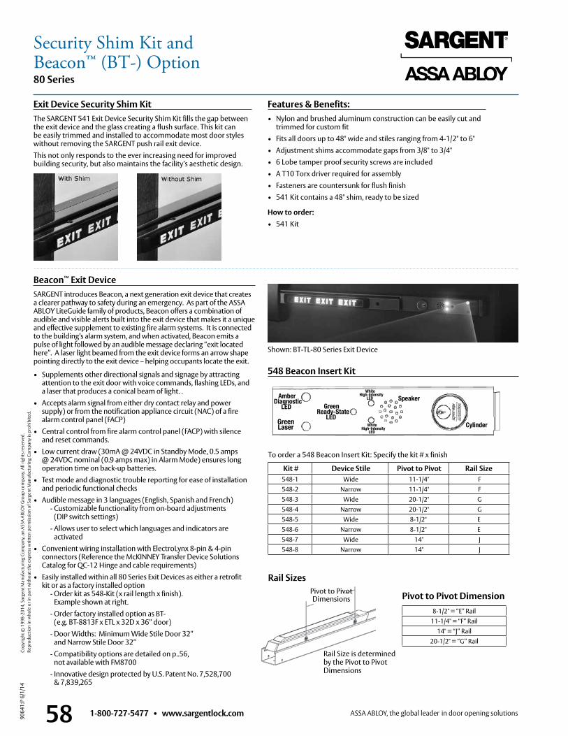
1-800-727-5477 • www.sargentlock.com58
80 Series
9064
1:P
6/1/
14
Copy
right
© 1
998-
2014
, Sar
gent
Man
ufac
turin
g Co
mpa
ny, a
n AS
SA A
BLO
Y G
roup
com
pany
. All
right
s res
erve
d.
Re
prod
uctio
n in
who
le o
r in
part
with
out t
he e
xpre
ss w
ritte
n pe
rmis
sion
of S
arge
nt M
anuf
actu
ring
Com
pany
is p
rohi
bite
d.
Beacon™ Exit DeviceSARGENT introduces Beacon, a next generation exit device that creates a clearer pathway to safety during an emergency . As part of the ASSA ABLOY LiteGuide family of products, Beacon offers a combination of audible and visible alerts built into the exit device that makes it a unique and effective supplement to existing fire alarm systems . It is connected to the building’s alarm system, and when activated, Beacon emits a pulse of light followed by an audible message declaring “exit located here” . A laser light beamed from the exit device forms an arrow shape pointing directly to the exit device – helping occupants locate the exit .
548 Beacon Insert Kit• Supplements other directional signals and signage by attracting attention to the exit door with voice commands, flashing LEDs, and a laser that produces a conical beam of light . .
• Accepts alarm signal from either dry contact relay and power supply) or from the notification appliance circuit (NAC) of a fire alarm control panel (FACP)
• Central control from fire alarm control panel (FACP) with silence and reset commands .
• Low current draw (30mA @ 24VDC in Standby Mode, 0 .5 amps @ 24VDC nominal (0 .9 amps max) in Alarm Mode) ensures long operation time on back-up batteries .
• Test mode and diagnostic trouble reporting for ease of installation and periodic functional checks
• Audible message in 3 languages (English, Spanish and French) - Customizable functionality from on-board adjustments
(DIP switch settings) - Allows user to select which languages and indicators are
activated• Convenient wiring installation with ElectroLynx 8-pin & 4-pin
connectors (Reference the McKINNEY Transfer Device Solutions Catalog for QC-12 Hinge and cable requirements)
• Easily installed within all 80 Series Exit Devices as either a retrofit kit or as a factory installed option
- Order kit as 548-Kit (x rail length x finish) . Example shown at right .
- Order factory installed option as BT- (e .g . BT-8813F x ETL x 32D x 36” door)
- Door Widths: Minimum Wide Stile Door 32” and Narrow Stile Door 32”
- Compatibility options are detailed on p . .56, not available with FM8700
- Innovative design protected by U .S . Patent No . 7,528,700 & 7,839,265
Shown: BT-TL-80 Series Exit Device
White High-Intensity
LED SpeakerGreen
Ready-State LED
Green Laser
Amber Diagnostic
LED
CylinderWhite High-Intensity
LED
To order a 548 Beacon Insert Kit: Specify the kit # x finish
Exit Device Security Shim KitThe SARGENT 541 Exit Device Security Shim Kit fills the gap between the exit device and the glass creating a flush surface . This kit can be easily trimmed and installed to accommodate most door styles without removing the SARGENT push rail exit device .This not only responds to the ever increasing need for improved building security, but also maintains the facility’s aesthetic design .
Features & Benefits:• Nylon and brushed aluminum construction can be easily cut and
trimmed for custom fit• Fits all doors up to 48" wide and stiles ranging from 4-1/2" to 6"• Adjustment shims accommodate gaps from 3/8" to 3/4"• 6 Lobe tamper proof security screws are included• A T10 Torx driver required for assembly• Fasteners are countersunk for flush finish• 541 Kit contains a 48" shim, ready to be sized
How to order:• 541 Kit
Rail Size is determined by the Pivot to Pivot Dimensions
8-1/2" = “E” Rail11-1/4" = “F” Rail
14" = “J” Rail20-1/2" = “G” Rail
Pivot to Pivot Dimension
Rail SizesPivot to Pivot Dimensions
Kit # Device Stile Pivot to Pivot Rail Size 548-1 Wide 11-1/4" F 548-2 Narrow 11-1/4" F 548-3 Wide 20-1/2" G 548-4 Narrow 20-1/2" G 548-5 Wide 8-1/2" E548-6 Narrow 8-1/2" E548-7 Wide 14" J 548-8 Narrow 14" J
Security Shim Kit andBeacon™ (BT-) Option
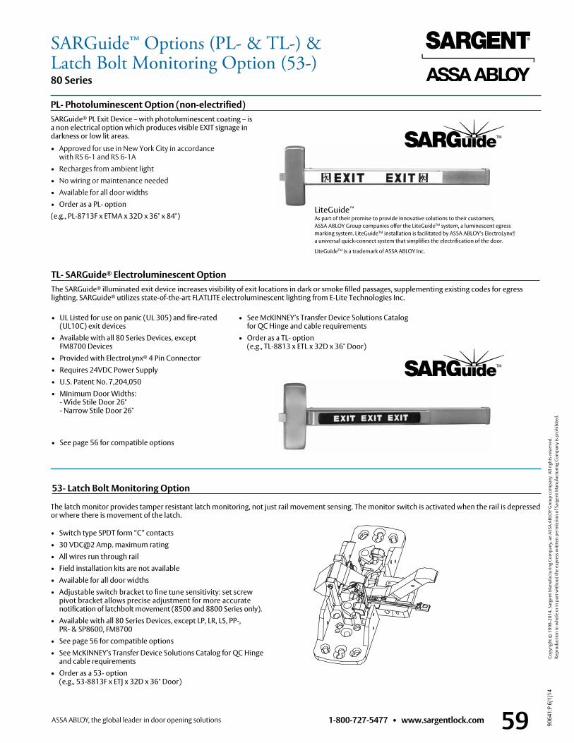
1-800-727-5477 • www.sargentlock.com 59
80 Series
9064
1:P
6/1/
14
Copy
right
© 1
998-
2014
, Sar
gent
Man
ufac
turin
g Co
mpa
ny, a
n AS
SA A
BLO
Y G
roup
com
pany
. All
right
s res
erve
d.
Re
prod
uctio
n in
who
le o
r in
part
with
out t
he e
xpre
ss w
ritte
n pe
rmis
sion
of S
arge
nt M
anuf
actu
ring
Com
pany
is p
rohi
bite
d.
The latch monitor provides tamper resistant latch monitoring, not just rail movement sensing . The monitor switch is activated when the rail is depressed or where there is movement of the latch .
53- Latch Bolt Monitoring Option
• Switch type SPDT form “C” contacts• 30 VDC@2 Amp . maximum rating• All wires run through rail• Field installation kits are not available• Available for all door widths• Adjustable switch bracket to fine tune sensitivity: set screw
pivot bracket allows precise adjustment for more accurate notification of latchbolt movement (8500 and 8800 Series only) .
• Available with all 80 Series Devices, except LP, LR, LS, PP-, PR- & SP8600, FM8700
• See page 56 for compatible options • See McKINNEY’s Transfer Device Solutions Catalog for QC Hinge
and cable requirements• Order as a 53- option
(e .g ., 53-8813F x ETJ x 32D x 36" Door)
PL- Photoluminescent Option (non-electrified)SARGuide® PL Exit Device – with photoluminescent coating – is a non electrical option which produces visible EXIT signage in darkness or low lit areas .
• Approved for use in New York City in accordance with RS 6-1 and RS 6-1A
• Recharges from ambient light• No wiring or maintenance needed• Available for all door widths• Order as a PL- option(e .g ., PL-8713F x ETMA x 32D x 36" x 84")
TL- SARGuide® Electroluminescent OptionThe SARGuide® illuminated exit device increases visibility of exit locations in dark or smoke filled passages, supplementing existing codes for egress lighting . SARGuide® utilizes state-of-the-art FLATLITE electroluminescent lighting from E-Lite Technologies Inc .
• UL Listed for use on panic (UL 305) and fire-rated (UL10C) exit devices
• Available with all 80 Series Devices, except FM8700 Devices
• Provided with ElectroLynx® 4 Pin Connector• Requires 24VDC Power Supply• U .S . Patent No . 7,204,050• Minimum Door Widths:
- Wide Stile Door 26" - Narrow Stile Door 26"
• See page 56 for compatible options
• See McKINNEY’s Transfer Device Solutions Catalog for QC Hinge and cable requirements
• Order as a TL- option (e .g ., TL-8813 x ETL x 32D x 36" Door)
LiteGuide™
As part of their promise to provide innovative solutions to their customers, ASSA ABLOY Group companies offer the LiteGuideTM system, a luminescent egress marking system . LiteGuideTM installation is facilitated by ASSA ABLOY’s ElectroLynx®, a universal quick-connect system that simplifies the electrification of the door .
LiteGuideTM is a trademark of ASSA ABLOY Inc .
SARGuide™ Options (PL- & TL-) &Latch Bolt Monitoring Option (53-)
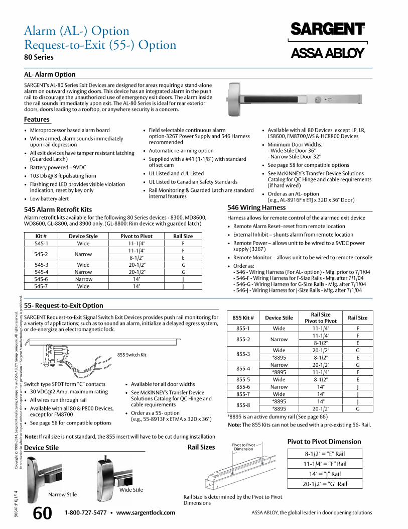
1-800-727-5477 • www.sargentlock.com60
80 Series
9064
1:P
6/1/
14
Copy
right
© 1
998-
2014
, Sar
gent
Man
ufac
turin
g Co
mpa
ny, a
n AS
SA A
BLO
Y G
roup
com
pany
. All
right
s res
erve
d.
Re
prod
uctio
n in
who
le o
r in
part
with
out t
he e
xpre
ss w
ritte
n pe
rmis
sion
of S
arge
nt M
anuf
actu
ring
Com
pany
is p
rohi
bite
d.
SARGENT’s AL-80 Series Exit Devices are designed for areas requiring a stand-alone alarm on outward swinging doors . This device has an integrated alarm in the push rail to discourage the unauthorized use of emergency exit doors . The alarm inside the rail sounds immediately upon exit . The AL-80 Series is ideal for rear exterior doors, doors leading to a rooftop, or anywhere security is a concern .
AL- Alarm Option
Features• Microprocessor based alarm board• When armed, alarm sounds immediately
upon rail depression• All exit devices have tamper resistant latching
(Guarded Latch)• Battery powered – 9VDC• 103 Db @ 8 ft pulsating horn• Flashing red LED provides visible violation
indication, reset by key only• Low battery alert
• Field selectable continuous alarm option-3267 Power Supply and 546 Harness recommended
• Automatic re-arming option • Supplied with a #41 (1-1/8") with standard
off set cam• UL Listed and cUL Listed• UL Listed to Canadian Safety Standards• Rail Monitoring & Guarded Latch are standard
internal features
• Available with all 80 Devices, except LP, LR, LS8600, FM8700,WS & HC8800 Devices
• Minimum Door Widths: - Wide Stile Door 36" - Narrow Stile Door 32"
• See page 58 for compatible options • See McKINNEY’s Transfer Device Solutions
Catalog for QC Hinge and cable requirements (if hard wired)
• Order as an AL- option (e .g ., AL-8916F x ETJ x 32D x 36" Door)
546 Wiring HarnessHarness allows for remote control of the alarmed exit device• Remote Alarm Reset–reset from remote location• External Inhibit – shunts alarm from remote location• Remote Power – allows unit to be wired to a 9VDC power
supply (3267)• Remote Monitor – allows unit to be wired to remote console• Order as:
- 546 - Wiring Harness (For AL- option) - Mfg . prior to 7/1/04 - 546-F - Wiring Harness for F-Size Rails - Mfg . after 7/1/04 - 546-G - Wiring Harness for G-Size Rails - Mfg . after 7/1/04 - 546-J - Wiring Harness for J-Size Rails - Mfg . after 7/1/04
545 Alarm Retrofit KitsAlarm retrofit kits available for the following 80 Series devices - 8300, MD8600, WD8600, GL-8800, and 8900 only . (GL-8800: Rim device with guarded latch)
SARGENT Request-to-Exit Signal Switch Exit Devices provides push rail monitoring for a variety of applications; such as to sound an alarm, initialize a delayed egress system, or de-energize an electromagnetic lock .
55- Request-to-Exit Option
Switch type SPDT form “C” contacts• 30 VDC@2 Amp . maximum rating• All wires run through rail• Available with all 80 & P800 Devices,
except for FM8700• See page 58 for compatible options
• Available for all door widths• See McKINNEY‘s Transfer Device
Solutions Catalog for QC Hinge and cable requirements
• Order as a 55- option (e .g ., 55-8913F x ETMA x 32D x 36")
855 Switch Kit
Note: If rail size is not standard, the 855 insert will have to be cut during installation
Note: The 855 Kits can not be used with a pre-existing 56- Rail .
855 Kit # Device Stile Rail SizePivot to Pivot Rail Size
855-1 Wide 11-1/4" F
855-2 Narrow 11-1/4" F8-1/2" E
855-3Wide 20-1/2" G*8895 8-1/2" E
855-4 Narrow 20-1/2" G*8895 11-1/4" F
855-5 Wide 8-1/2" E855-6 Narrow 14" J855-7 Wide 14" J
855-8 *8895 14" J*8895 20-1/2" G
Device Stile
Narrow StileWide Stile
Rail Size is determined by the Pivot to Pivot Dimensions
8-1/2" = “E” Rail
11-1/4" = “F” Rail
14" = “J” Rail
20-1/2" = “G” Rail
Pivot to Pivot DimensionRail Sizes
*8895 is an active dummy rail (See page 66)
Pivot to Pivot Dimension
Kit # Device Style Pivot to Pivot Rail Size 545-1 Wide 11-1/4" F
545-2 Narrow 11-1/4" F8-1/2" E
545-3 Wide 20-1/2" G 545-4 Narrow 20-1/2" G 545-6 Narrow 14" J545-7 Wide 14" J
Alarm (AL-) OptionRequest-to-Exit (55-) Option
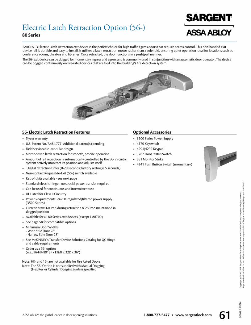
1-800-727-5477 • www.sargentlock.com 61
80 Series
9064
1:P
6/1/
14
Copy
right
© 1
998-
2014
, Sar
gent
Man
ufac
turin
g Co
mpa
ny, a
n AS
SA A
BLO
Y G
roup
com
pany
. All
right
s res
erve
d.
Re
prod
uctio
n in
who
le o
r in
part
with
out t
he e
xpre
ss w
ritte
n pe
rmis
sion
of S
arge
nt M
anuf
actu
ring
Com
pany
is p
rohi
bite
d.
56- Electric Latch Retraction Features• 5 year warranty• U .S . Patent No . 7,484,777; Additional patent(s) pending• Field serviceable -modular design• Motor driven latch retraction for smooth, precise operation• Amount of rail retraction is automatically controlled by the 56- circuitry;
System actively monitors its position and adjusts itself• Digital retraction timer (0-20 seconds; factory setting is 5 seconds)• Non-contact Request-to-Exit (55-) switch available• Retrofit kits available - see next page• Standard electric hinge - no special power transfer required• Can be used for continuous and intermittent use• UL Listed for Class II Circuitry• Power Requirements: 24VDC regulated/filtered power supply
(3500 Series)• Current draw: 600mA during retraction & 250mA maintained in
dogged position• Available for all 80 Series exit devices (except FM8700)• See page 58 for compatible options • Minimum Door Widths:
- Wide Stile Door 28" - Narrow Stile Door 28"
• See McKINNEY’s Transfer Device Solutions Catalog for QC Hinge and cable requirements
• Order as a 56- option (e .g ., 56-HK-8913F x ETMF x 32D x 36")
Note: HK- and 16- are not available for Fire Rated DoorsNote: The 56- Option is not supplied with Manual Dogging
(Hex Key or Cylinder Dogging) unless specified
SARGENT’s Electric Latch Retraction exit device is the perfect choice for high traffic egress doors that require access control . This non-handed exit device rail is durable and easy to install . It utilizes a latch retraction motor rather than a solenoid, ensuring quiet operation ideal for locations such as conference rooms, theaters and libraries . Once retracted, the door functions in a push/pull manner .The 56- exit device can be dogged for momentary ingress and egress and is commonly used in conjunction with an automatic door operator . The device can be dogged continuously on fire-rated devices that are tied into the building’s fire detection system .
Optional Accessories • 3500 Series Power Supply• 4370 Keyswitch• 4291/4292 Keypad• 3287 Door Status Switch• 881 Monitor Strike• 4341 Push Button Switch (momentary)
Electric Latch Retraction Option (56-)
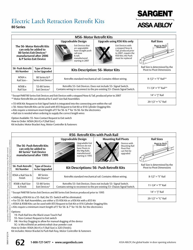
1-800-727-5477 • www.sargentlock.com62
80 Series
9064
1:P
6/1/
14
Copy
right
© 1
998-
2014
, Sar
gent
Man
ufac
turin
g Co
mpa
ny, a
n AS
SA A
BLO
Y G
roup
com
pany
. All
right
s res
erve
d.
Re
prod
uctio
n in
who
le o
r in
part
with
out t
he e
xpre
ss w
ritte
n pe
rmis
sion
of S
arge
nt M
anuf
actu
ring
Com
pany
is p
rohi
bite
d.
M56- Motor Retrofit Kits
The 56- Motor Retrofit Kits can only be added to
80 Series Exit Devices* manufactured after 2006
& P Series Exit Device
Upgradeable Design
Upgrade using R56 Kits only
Rail Sizes
Rail Size is determined by the Pivot to Pivot Dimensions56- Push Retrofit
Kit NumberType of Device
to be Upgraded Kits Description: 56- Motor Kits
M56A xRail Size--
80 Series & P Series Exit Device* Retrofits standard mechanical rail . Contains ribbon wiring . 8-1/2" = “E” Rail**
M56B xRail Size
53-80 Series Exit Devices*
Retrofits 53- Exit Devices . Does not include 53- Signal Switch .Contains wiring to reconnect to the pre-existing 53- Chassis Signal Switch . 11-1/4" = “F” Rail**
14" = “J” Rail
20-1/2" = “G” Rail
X
* Except FM8700 Series Exit Devices and Exit Devices with a stepped Nose & Tail, produced prior to 2007** Motor Retrofit Kits are identical for E and F size Rail Assemblies
• 55-M56 Kit: Request to Exit Signal Switch is integrated into the connecting arm within the rail• 56- Motor Retrofit Kits can be used with 855 Request to Exit Kit or 816 Cylinder Dogging Kits• Kits require a minimum insert length of 5" for 56- & 7" for 16-56- for the electronics• Rail size is needed when ordering to supply the correct length wires
Option Available: 55- Non-Contact Request to Exit switchHow to Order: M56A (Kit #) x F (Rail Size)Kit includes: Motor Bracket Assy, Motor Controller & Fasteners
Exit Devices that are upgradable have straight push rail nose & tail; manufactured starting in 2007
Exit Devices with a stepped Nose & Tail, produced prior to 2007, require the R56 Kits; the Push must be replaced
R56- Retrofit Kits with Push Rail
The 56- Push Retrofit Kits can only be added to80 Series* Exit Device
manufactured after 1995
Upgradeable Design
Mounting Rail Pivots
Rail Sizes
Rail Size is determined by the Pivot to Pivot Dimensions56- Push Retrofit
Kit NumberType of Device
to be Upgraded Kit Descriptions: 56- Push Retrofit Kits
R56A x Rail Size & Finish
80 Series Exit Device* Retrofits standard mechanical rail . Contains ribbon wiring . 8-1/2" = ”E” Rail
R56B x Rail Size & Finish
53-80 Series Exit Devices*
Retrofits 53- Exit Devices . Does not include 53- Signal Switch .Contains wiring to reconnect to the pre-existing 53- Chassis Signal Switch . 11-1/4" = ”F” Rail
14" = ”J” Rail
20-1/2" = ”G” Rail
Upgradable Exit Devices do not have Pivots in the Mtg Rails; manufactured starting in 1995
Devices withMounting RailPivot Pins can Not be upgraded
* Except FM8700 Series Exit Devices and 80 Series Exit Devices produced prior to 1995
• Adding a R56 Kit to a 55- Rail, the 55- Switch will be eliminated .• For 55-56- Rail Assemblies, use either a 55-R56 Kit or a R56 Kit with a 855 Kit• R56A & R56B Kits can be used with 855 Request to Exit Kit or 816 Cylinder Dogging Kits• Kits require a minimum insert length of 5" for 56- & 7" for 16-56- for the electronics
Options: 19- Push Rail less the Black Lexan Touch Pad 55- Non-Contact Request to Exit switch HK- Hex Key Dogging to allow for manual dogging of the device SG- is MicroShield an antimicrobial clear powder coatHow to Order: R56A (Kit #) x F (Rail Size) x 32D (Finish);Kit includes: Motor Bracket & Push Rail Assy, Motor Controller & Fasteners
Electric Latch Retraction Retrofit Kits
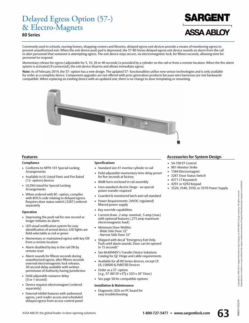
1-800-727-5477 • www.sargentlock.com 63
80 Series
9064
1:P
6/1/
14
Copy
right
© 1
998-
2014
, Sar
gent
Man
ufac
turin
g Co
mpa
ny, a
n AS
SA A
BLO
Y G
roup
com
pany
. All
right
s res
erve
d.
Re
prod
uctio
n in
who
le o
r in
part
with
out t
he e
xpre
ss w
ritte
n pe
rmis
sion
of S
arge
nt M
anuf
actu
ring
Com
pany
is p
rohi
bite
d.
Accessories for System Design• 54-700 ET Control• 881 Monitor Strike• 1584 Electromagnet• 3287 Door Status Switch• 4371 LT Keyswitch• 4291 or 4292 Keypad• 3520, 3540, 3550, or 3570 Power Supply
FeaturesCompliance• Conforms to NFPA 101 Special Locking
Arrangements• Available in UL Listed Panic and Fire Rated
(12- option) devices• UL294 Listed for Special Locking
Arrangements• When ordered with BC- option, complies
with BOCA code relating to delayed egress . Requires door status switch (3287) ordered separately
Operation• Depressing the push rail for one second or
longer initiates an alarm• LED visual notification system for easy
identification of armed device; LED lights are field-selectable as red or green
• Momentary or maintained egress with key OR from a remote location
• Alarm disabled by key in the rail OR by remote reset
• Alarm sounds for fifteen seconds during unauthorized egress; after fifteen seconds external electromagnetic lock releases . 30 second delay available with written permission of Authority having Jurisdiction
• Field adjustable nuisance delay (0 or 1 second)
• Device requires electromagnet (ordered separately)
• External inhibit features with authorized egress, card reader access and scheduled delayed egress from access control panel
Specifications• Standard size 41 mortise cylinder in rail • Field adjustable momentary time delay preset
for five seconds at factory• 80dB horn enclosed in rail assembly• Uses standard electric hinge - no special
power transfer required• Guarded & monitored latch and rail standard• Power Requirements: 24VDC regulated/
filtered power supply• Key override capabilities• Current draw: .2 amp . nominal, .5 amp (max)
with optional features ( .275 amp maximum electromagnetic load)
• Minimum Door Widths: - Wide Stile Door 32” - Narrow Stile Door 32”• Shipped with decal “Emergency Exit Only .
Push until alarm sounds . Door can be opened in 15 seconds”
• See McKINNEY‘s Transfer Device Solutions Catalog for QC Hinge and cable requirements
• Available for all 80 Series devices, except LP, LR, LS8600 & FM8700 Devices
• Order as a 57- option (e .g ., 57-8813F x ETJ x 32D x 36” Door)
• See page 58 for compatible options
Installation & Maintenance• Diagnostic LEDs on PC board for
easy troubleshooting
Delayed Egress Option (57-)& Electro-Magnets
Commonly used in schools, nursing homes, shopping centers and libraries, delayed egress exit devices provide a means of monitoring egress to prevent unauthorized exit . When the exit device push pad is depressed, the 57-80 Series delayed egress exit device sounds an alarm from the rail to alert personnel that someone is attempting egress . The exit device stays secure, via electromagnetic lock, for fifteen seconds, allowing time for personnel to respond .Momentary release for egress (adjustable for 5, 10, 20 or 40 seconds) is provided by a cylinder on the rail or from a remote location . When the fire alarm system is activated (if connected), the exit device disarms and allows immediate egress .Note: As of February 2014, the 57- option has a new design . The updated 57- functionalities utilize new sensor technologies and is only available for order as a complete device . Component upgrades are not offered with prior generation products because wire harnesses are not backwards compatible . When replacing an existing device with an updated one, there is no change to door templating or mounting .
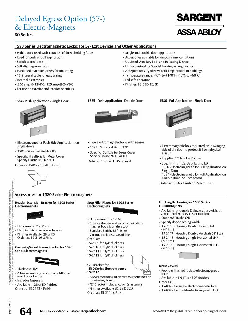
1-800-727-5477 • www.sargentlock.com64
80 Series
9064
1:P
6/1/
14
Copy
right
© 1
998-
2014
, Sar
gent
Man
ufac
turin
g Co
mpa
ny, a
n AS
SA A
BLO
Y G
roup
com
pany
. All
right
s res
erve
d.
Re
prod
uctio
n in
who
le o
r in
part
with
out t
he e
xpre
ss w
ritte
n pe
rmis
sion
of S
arge
nt M
anuf
actu
ring
Com
pany
is p
rohi
bite
d.
• Hold door closed with 1200 lbs . of direct holding force• Used for push or pull applications• Stainless steel case• Self aligning armature• Hardened machine screws for mounting• 10’ integral cable for easy wiring• Internal electronics• .250 amp @ 12VDC, .125 amp @ 24VDC• For use on exterior and interior openings
• Single and double door applications• Accessories available for various frame conditions• UL Listed, Auxiliary Lock and Releasing Device• UL Recognized for Special Locking Arrangements• Accepted for City of New York, Department of Buildings• Temperature range: -40°F to +140°F (-40°C to +60°C)• Fail safe operation• Finishes: 28, 32D, EB, ED
1580 Series Electromagnetic Locks: For 57- Exit Devices and Other Applications
1584 - Push Application - Single Door
• Electromagnet for Push Side Applications on single doors
• 1584 – Standard Finish 32D • Specify: H Suffix is for Metal Cover
Specify Finish: 28, EB or EDOrder as: 1584 or 1584H x Finish
1585 - Push Application - Double Door
• Two electromagnetic locks with sensor• 1585 – Standard Finish 32D • Specify: J Suffix is for Dress Cover
Specify Finish: 28, EB or EDOrder as: 1585 or 1585J x Finish
1586 - Pull Application - Single Door
• Electromagnetic lock mounted on inswinging side of the door to protect it from physical assault
• Supplied “Z” bracket & cover • Specify Finish: 28, 32D, EB and ED
1586 - Electromagnetic for Pull Application on Single Door 1587 - Electromagnetic for Pull Application on Double Door includes sensor
Order as: 1586 x Finish or 1587 x Finish
Accessories for 1580 Series Electromagnets
Header Extension Bracket for 1508 Series Electromagnets
• Dimensions: 3" x 3" x 8"• Used to extend a narrow header• Finishes Available: 28 or ED
Order as: 15-2107 x Finish
Concrete/Wood Frame Bracket for 1580 Series Electromagnets
• Thickness: 1/2"• Allows mounting on concrete filled or wood door frames• Includes Fasteners• Available in 28 or ED finishesOrder as: 15-2113 x Finish
Stop Filler Plates for 1508 Series Electromagnets
• Dimensions: 8" x 1-1/4"• Extends the stop when only part of the
magnet body is on the stop• Standard Finish: 28 finishes• Various thicknesses availableOrder as:15-2109 for 1/4" thickness15-2110 for 3/8" thickness15-2111 for 1/2" thickness15-2112 for 5/8" thickness
“Z” Bracket for 1580 Series Electromagnet 15-2114• Allows mounting of electromagnetic lock on
inswinging doors• “Z” Bracket includes cover & fasteners• Finishes Available ED, 28 & 32DOrder as: 15-2114 x Finish
Full Length Housing for 1580 Series Electromagnets• Available for double & single doors without vertical rod exit devices or mullion• Standard Finish: 32D• Specify door opening width• 15-2116 - Housing Double Horizontal
(96" Std)• 15-2117 - Housing Double Vertical (96" Std)• 15-2118 - Housing Single Horizontal LHR
(48" Std)• 15-2119 - Housing Single Horizontal RHR
(48" Std)
Dress Covers• Provides finished look to electromagnetic
locks• Available in EN, EB, and 28 finishesOrder as:• 15-0078 for single electromagnetic lock• 15-0079 for double electromagnetic lock
Delayed Egress Option (57-)& Electro-Magnets
1-800-727-5477 • www.sargentlock.com 65
80 Series
9064
1:P
6/1/
14
Copy
right
© 1
998-
2014
, Sar
gent
Man
ufac
turin
g Co
mpa
ny, a
n AS
SA A
BLO
Y G
roup
com
pany
. All
right
s res
erve
d.
Re
prod
uctio
n in
who
le o
r in
part
with
out t
he e
xpre
ss w
ritte
n pe
rmis
sion
of S
arge
nt M
anuf
actu
ring
Com
pany
is p
rohi
bite
d.
• Provides quiet ingress and egress when dogged• Standard electric hinge - no special power transfer required• Manual hex key dogging provided on non-fire rated devices• UL Listed for Panic and Fire (12-)• Holding force 70 lbs . min .• Power Requirements: 24VDC regulated/filtered power supply
(3500 Series)• Current draw: .2 amp• Available for all 80 Series Devices, except FM8700 Devices• See page 58 for compatible options
• Available for all door widths• See McKINNEY’s Transfer Device Solutions Catalog for QC Hinge and
cable requirements• Order as a 58- option (e .g ., 58-8813F x ETJ x 32D x 36" Door)
Optional Accessories• 4370 Key Switch• 881 Monitor Strike• 3287 Door Status Switch• 3520, 3540, 3550, or 3570 Power Supply
58- Features
58- Electric DoggingLibraries, auditoriums, theaters, courtrooms, churches and schools benefit from the convenience of electric dogging (unlocking) . When the 58-80 Series exit device is energized and the push rail is depressed, it will continuously hold the push rail down and the latch(es) will be held retracted . When the device is de-energized or power is interrupted, the latch(es) will extend . This feature is ideal for areas that require the silent operation of exit device hardware .
Electric Dogging Option (58-)
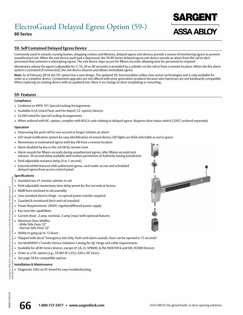
1-800-727-5477 • www.sargentlock.com66
80 Series
9064
1:P
6/1/
14
Copy
right
© 1
998-
2014
, Sar
gent
Man
ufac
turin
g Co
mpa
ny, a
n AS
SA A
BLO
Y G
roup
com
pany
. All
right
s res
erve
d.
Re
prod
uctio
n in
who
le o
r in
part
with
out t
he e
xpre
ss w
ritte
n pe
rmis
sion
of S
arge
nt M
anuf
actu
ring
Com
pany
is p
rohi
bite
d.
Compliance• Conforms to NFPA 101 Special Locking Arrangements• Available in UL Listed Panic and Fire Rated (12- option) devices• UL294 Listed for Special Locking Arrangements• When ordered with BC- option, complies with BOCA code relating to delayed egress . Requires door status switch (3287) ordered separately
Operation• Depressing the push rail for one second or longer initiates an alarm• LED visual notification system for easy identification of armed device; LED lights are field-selectable as red or green• Momentary or maintained egress with key OR from a remote location• Alarm disabled by key in the rail OR by remote reset • Alarm sounds for fifteen seconds during unauthorized egress; after fifteen seconds lock
releases . 30 second delay available with written permission of Authority having Jurisdiction • Field adjustable nuisance delay (0 or 1 second)• External inhibit features with authorized egress, card reader access and scheduled delayed egress from access control panel
Specifications• Standard size 41 mortise cylinder in rail • Field adjustable momentary time delay preset for five seconds at factory• 80dB horn enclosed in rail assembly• Uses standard electric hinge - no special power transfer required• Guarded & monitored latch and rail standard• Power Requirements: 24VDC regulated/filtered power supply• Key override capabilities• Current draw: .2 amp . nominal, .5 amp (max) with optional features• Minimum Door Widths: - Wide Stile Door 32" - Narrow Stile Door 32"• Ability to gang up to 12 doors• Shipped with decal “Emergency Exit Only . Push until alarm sounds . Door can be opened in 15 seconds”• See McKINNEY’s Transfer Device Solutions Catalog for QC Hinge and cable requirements• Available for all 80 Series devices, except LP, LR, LS, SP8600, & FM, ND8700 & and MS, HC800 Devices• Order as a 59- option (e .g ., 59-8813F x ETJ x 32D x 36" Door)• See page 58 for compatible options
Installation & Maintenance• Diagnostic LEDs on PC board for easy troubleshooting
59- Self Contained Delayed Egress DeviceCommonly used in schools, nursing homes, shopping centers and libraries, delayed egress exit devices provide a means of monitoring egress to prevent unauthorized exit . When the exit device push pad is depressed, the 59-80 Series delayed egress exit device sounds an alarm from the rail to alert personnel that someone is attempting egress . The exit device stays secure for fifteen seconds, allowing time for personnel to respond .Momentary release for egress (adjustable for 5, 10, 20 or 40 seconds) is provided by a cylinder on the rail or from a remote location . When the fire alarm system is activated (if connected), the exit device disarms and allows immediate egress .Note: As of February 2014, the 59- option has a new design . The updated 59- functionalities utilize new sensor technologies and is only available for order as a complete device . Component upgrades are not offered with prior generation products because wire harnesses are not backwards compatible . When replacing an existing device with an updated one, there is no change to door templating or mounting .
ElectroGuard Delayed Egress Option (59-)
59- Features
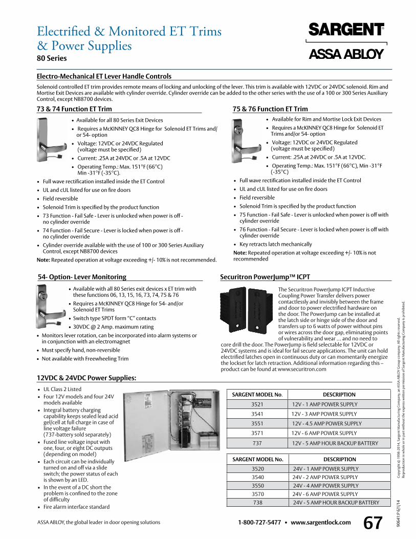
1-800-727-5477 • www.sargentlock.com 67
80 Series
9064
1:P
6/1/
14
Copy
right
© 1
998-
2014
, Sar
gent
Man
ufac
turin
g Co
mpa
ny, a
n AS
SA A
BLO
Y G
roup
com
pany
. All
right
s res
erve
d.
Re
prod
uctio
n in
who
le o
r in
part
with
out t
he e
xpre
ss w
ritte
n pe
rmis
sion
of S
arge
nt M
anuf
actu
ring
Com
pany
is p
rohi
bite
d.
Electrified & Monitored ET Trims& Power Supplies
• Available for all 80 Series Exit Devices• Requires a McKINNEY QC8 Hinge for Solenoid ET Trims and/
or 54- option• Voltage: 12VDC or 24VDC Regulated
(voltage must be specified) • Current: .25A at 24VDC or .5A at 12VDC• Operating Temp .: Max . 151°F (66°C)
Min -31°F (-35°C) .• Full wave rectification installed inside the ET Control• UL and cUL listed for use on fire doors• Field reversible• Solenoid Trim is specified by the product function• 73 Function - Fail Safe - Lever is unlocked when power is off -
no cylinder override• 74 Function - Fail Secure - Lever is locked when power is off -
no cylinder override• Cylinder override available with the use of 100 or 300 Series Auxiliary
Control, except NB8700 devicesNote: Repeated operation at voltage exceeding +/- 10% is not recommended .
• Available for Rim and Mortise Lock Exit Devices• Requires a McKINNEY QC8 Hinge for Solenoid ET
Trims and/or 54- option• Voltage: 12VDC or 24VDC Regulated
(voltage must be specified) • Current: .25A at 24VDC or .5A at 12VDC .• Operating Temp .: Max . 151°F (66°C), Min -31°F
(-35°C)• Full wave rectification installed inside the ET Control• UL and cUL listed for use on fire doors• Field reversible• Solenoid Trim is specified by the product function• 75 Function - Fail Safe - Lever is unlocked when power is off with
cylinder override• 76 Function - Fail Secure - Lever is locked when power is off with
cylinder override• Key retracts latch mechanicallyNote: Repeated operation at voltage exceeding +/- 10% is not recommended
• Available with all 80 Series exit devices x ET trim with these functions 06, 13, 15, 16, 73, 74, 75 & 76
• Requires a McKINNEY QC8 Hinge for 54- and/or Solenoid ET Trims
• Switch type SPDT form “C” contacts• 30VDC @ 2 Amp . maximum rating
• Monitors lever rotation, can be incorporated into alarm systems or in conjunction with an electromagnet
• Must specify hand, non-reversible • Not available with Freewheeling Trim
Electro-Mechanical ET Lever Handle ControlsSolenoid controlled ET trim provides remote means of locking and unlocking of the lever . This trim is available with 12VDC or 24VDC solenoid . Rim and Mortise Exit Devices are available with cylinder override . Cylinder override can be added to the other series with the use of a 100 or 300 Series Auxiliary Control, except NB8700 devices .
73 & 74 Function ET Trim 75 & 76 Function ET Trim
54- Option- Lever Monitoring
SARGENT MODEL No. DESCRIPTION
3521 12V - 1 AMP POWER SUPPLY
3541 12V - 3 AMP POWER SUPPLY
3551 12V - 4.5 AMP POWER SUPPLY
3571 12V - 6 AMP POWER SUPPLY
737 12V - 5 AMP HOUR BACKUP BATTERY
12VDC & 24VDC Power Supplies:
Securitron PowerJump™ ICPT
SARGENT MODEL No. DESCRIPTION
3520 24V - 1 AMP POWER SUPPLY3540 24V - 2 AMP POWER SUPPLY3550 24V - 4 AMP POWER SUPPLY3570 24V - 6 AMP POWER SUPPLY738 24V - 5 AMP HOUR BACKUP BATTERY
• UL Class 2 Listed • Four 12V models and four 24V
models available• Integral battery charging
capability keeps sealed lead acid gel/cell at full charge in case of line voltage failure (737-battery sold separately)
• Fused line voltage input with one, four, or eight DC outputs (depending on model)
• Each circuit can be individually turned on and off via a slide switch; the power status of each is shown by an LED.
• In the event of a DC short the problem is confined to the zone of difficulty
• Fire alarm interface standard
The Securitron PowerJump ICPT Inductive Coupling Power Transfer delivers power contactlessly and invisibly between the frame and door to power electrified hardware on the door. The PowerJump can be installed at the latch side or hinge side of the door and transfers up to 6 watts of power without pins or wires across the door gap, eliminating points of vulnerability and wear … and no need to
core drill the door. The PowerJump is field selectable for 12VDC or 24VDC systems and is ideal for fail secure applications. The unit can hold electrified latches open in continuous duty or can momentarily energize the lockset for latch retraction. Additional information regarding this –product can be found at www.securitron.com
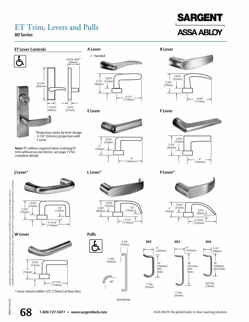
1-800-727-5477 • www.sargentlock.com68
80 Series
9064
1:P
6/1/
14
Copy
right
© 1
998-
2014
, Sar
gent
Man
ufac
turin
g Co
mpa
ny, a
n AS
SA A
BLO
Y G
roup
com
pany
. All
right
s res
erve
d.
Re
prod
uctio
n in
who
le o
r in
part
with
out t
he e
xpre
ss w
ritte
n pe
rmis
sion
of S
arge
nt M
anuf
actu
ring
Com
pany
is p
rohi
bite
d.
W Lever
J Lever*
Pulls
F LeverE Lever
P Lever*L Lever*
A Lever B LeverET Lever Controls
* Projection varies by lever design . 2-1/2" (63mm) projection with L Lever
* Lever returns within 1/2" (13mm) of door face
• Handed
3-1/8" (79mm)
13/16" (21mm)
4-5/8" (117mm)
864862
10"(254mm)MTG Holes
3-1/2"(89mm)
3/4” Dia .(19mm)
10"(254mm)MTG Holes
4"(102mm)
1” Dia .(25mm)
13/16" (21mm)
1-13/16" (46mm)
8-1/16" (205mm)
3-9/16" MAX* (90mm)
3-1/2" (89mm)
13/16" (21mm)
4-1/2" (114mm)
13/16" (21mm)
4" (102mm)
3-1/4" (83mm)3"
(76mm)
4" (102mm)
13/16" (21mm)
1/2" (13mm)2-3/4"
(70mm)
13/16" (21mm)
4-11/16" (119mm)
3" (76mm)
13/16" (21mm)
5/16" (8mm)
4-15/16" (125mm)
90°
1-3/4"(44mm)
2-3/4"(70mm)
3" (76mm)
13/16" (21mm)
4-11/16" (119mm)
13/16" (21mm)
4-1/2" (114mm)
1/2" (13mm)
2-3/8" (60mm)
SIDE PROFILE
Note: ET suffixes required when ordering ET trim without an exit device, see page 72 for complete details
863
18"(457mm)MTG Holes
4"(102mm)
1” Dia .(25mm)
ET Trim, Levers and Pulls
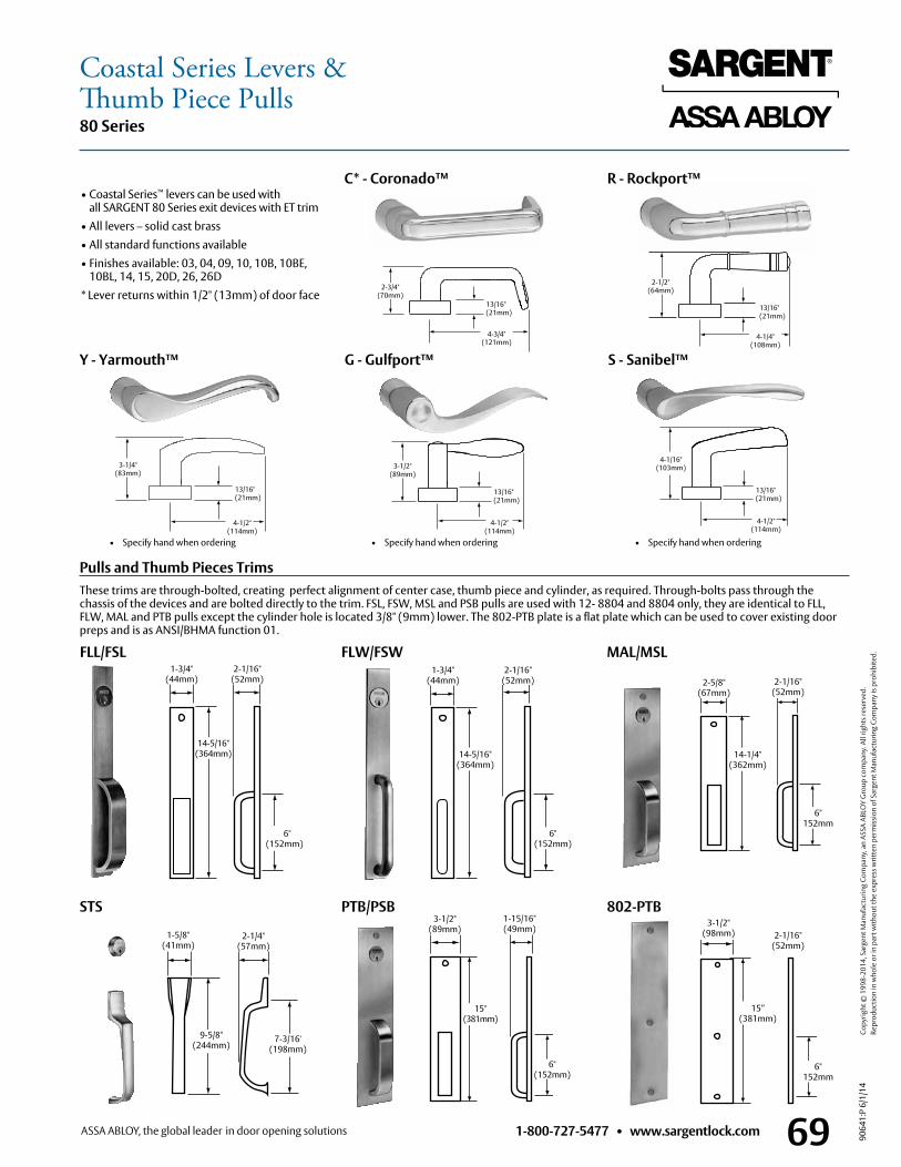
1-800-727-5477 • www.sargentlock.com 69
80 Series
9064
1:P
6/1/
14
Copy
right
© 1
998-
2014
, Sar
gent
Man
ufac
turin
g Co
mpa
ny, a
n AS
SA A
BLO
Y G
roup
com
pany
. All
right
s res
erve
d.
Re
prod
uctio
n in
who
le o
r in
part
with
out t
he e
xpre
ss w
ritte
n pe
rmis
sion
of S
arge
nt M
anuf
actu
ring
Com
pany
is p
rohi
bite
d.
Coastal Series Levers &Thumb Piece Pulls
• Specify hand when ordering• Specify hand when ordering • Specify hand when ordering
C* - Coronado™ R - Rockport™
Y - Yarmouth™ G - Gulfport™ S - Sanibel™
2-1/2"(64mm)
13/16"(21mm)
4-1/4"(108mm)
3-1/4"(83mm)
13/16"(21mm)
4-1/2"(114mm)
3-1/2"(89mm)
13/16"(21mm)
4-1/2"(114mm)
4-1/16"(103mm)
13/16"(21mm)
4-1/2"(114mm)
2-3/4" (70mm)
13/16"(21mm)
4-3/4"(121mm)
PTB/PSB
MAL/MSL
STS
FLW/FSWFLL/FSL1-3/4"
(44mm)2-1/16"
(52mm)
6" (152mm)
14-5/16" (364mm)
1-3/4" (44mm)
14-5/16" (364mm)
2-1/16" (52mm)
6" (152mm)
2-1/16" (52mm)
2-5/8" (67mm)
14-1/4" (362mm)
6" 152mm
802-PTB
2-1/16" (52mm)
3-1/2" (98mm)
15” (381mm)
6" 152mm
6" (152mm)
3-1/2" (89mm)
1-15/16" (49mm)
15" (381mm)
1-5/8" (41mm)
2-1/4" (57mm)
9-5/8" (244mm)
• Coastal Series™ levers can be used with all SARGENT 80 Series exit devices with ET trim
• All levers – solid cast brass• All standard functions available• Finishes available: 03, 04, 09, 10, 10B, 10BE,
10BL, 14, 15, 20D, 26, 26D* Lever returns within 1/2" (13mm) of door face
Pulls and Thumb Pieces TrimsThese trims are through-bolted, creating perfect alignment of center case, thumb piece and cylinder, as required . Through-bolts pass through the chassis of the devices and are bolted directly to the trim . FSL, FSW, MSL and PSB pulls are used with 12- 8804 and 8804 only, they are identical to FLL, FLW, MAL and PTB pulls except the cylinder hole is located 3/8" (9mm) lower . The 802-PTB plate is a flat plate which can be used to cover existing door preps and is as ANSI/BHMA function 01 .
7-3/16' (198mm)
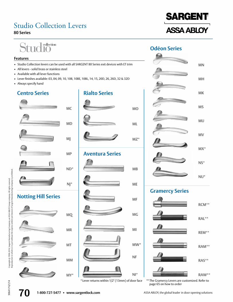
1-800-727-5477 • www.sargentlock.com70
80 Series
9064
1:P
6/1/
14
Copy
right
© 1
998-
2014
, Sar
gent
Man
ufac
turin
g Co
mpa
ny, a
n AS
SA A
BLO
Y G
roup
com
pany
. All
right
s res
erve
d.
Re
prod
uctio
n in
who
le o
r in
part
with
out t
he e
xpre
ss w
ritte
n pe
rmis
sion
of S
arge
nt M
anuf
actu
ring
Com
pany
is p
rohi
bite
d.
Features• Studio Collection levers can be used with all SARGENT 80 Series exit devices with ET trim• All levers - solid brass or stainless steel• Available with all lever functions• Lever finishes available: 03, 04, 09, 10, 10B, 10BE, 10BL, 14, 15, 20D, 26, 26D, 32 & 32D• Always specify hand
MO
ML
MZ*
MC
MD
MJ
MP
ND*
NJ*
MQ
MR
MT
MM
MY*
MB
ME
MF
MG
MI
MW*
MN
MH
MK
MS
MU
MV
MX*
NS*
NU*
RCM**
RAL**
REM**
RAM**
RAS**
RAW**
Rialto Series
Odéon Series
Aventura Series
Centro Series
Notting Hill Series
* Lever returns within 1/2" (13mm) of door face ** The Gramercy Levers are customized . Refer to page 65 on how to order
Gramercy Series
NF
NI*
Studio Collection Levers
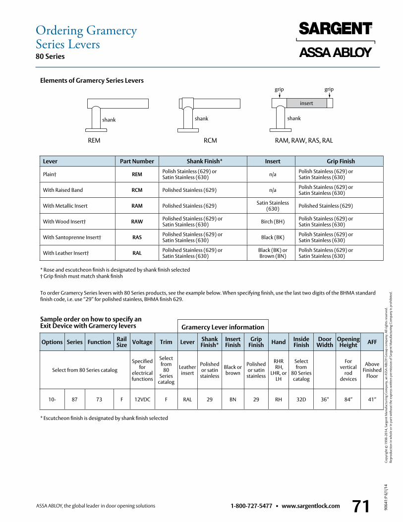
1-800-727-5477 • www.sargentlock.com 71
80 Series
9064
1:P
6/1/
14
Copy
right
© 1
998-
2014
, Sar
gent
Man
ufac
turin
g Co
mpa
ny, a
n AS
SA A
BLO
Y G
roup
com
pany
. All
right
s res
erve
d.
Re
prod
uctio
n in
who
le o
r in
part
with
out t
he e
xpre
ss w
ritte
n pe
rmis
sion
of S
arge
nt M
anuf
actu
ring
Com
pany
is p
rohi
bite
d.
Ordering GramercySeries Levers
Gramercy Lever information
Elements of Gramercy Series Levers
REM RCM RAM, RAW, RAS, RAL
Lever Part Number Shank Finish* Insert Grip Finish
Plain† REM Polish Stainless (629) or Satin Stainless (630) n/a Polish Stainless (629) or
Satin Stainless (630)
With Raised Band RCM Polished Stainless (629) n/a Polish Stainless (629) or Satin Stainless (630)
With Metallic Insert RAM Polished Stainless (629) Satin Stainless (630) Polished Stainless (629)
With Wood Insert† RAW Polished Stainless (629) or Satin Stainless (630) Birch (BH) Polish Stainless (629) or
Satin Stainless (630)
With Santoprenne Insert† RAS Polished Stainless (629) or Satin Stainless (630) Black (BK) Polish Stainless (629) or
Satin Stainless (630)
With Leather Insert† RAL Polished Stainless (629) or Satin Stainless (630)
Black (BK) or Brown (BN)
Polish Stainless (629) or Satin Stainless (630)
* Rose and escutcheon finish is designated by shank finish selected† Grip finish must match shank finish
* Escutcheon finish is designated by shank finish selected
To order Gramercy Series levers with 80 Series products, see the example below . When specifying finish, use the last two digits of the BHMA standard finish code, i .e . use “29” for polished stainless, BHMA finish 629 .
Options Series Function Rail Size Voltage Trim Lever Shank
Finish*Insert Finish
Grip Finish Hand Inside
FinishDoor
WidthOpening Height AFF
Select from 80 Series catalog
Specified for
electrical functions
Select from
80 Series
catalog
Leather insert
Polished or satin
stainless
Black or brown
Polished or satin
stainless
RHR RH,
LHR, or LH
Select from
80 Seriescatalog
For vertical
rod devices
Above Finished
Floor
10- 87 73 F 12VDC F RAL 29 BN 29 RH 32D 36” 84” 41”
Sample order on how to specify an Exit Device with Gramercy levers
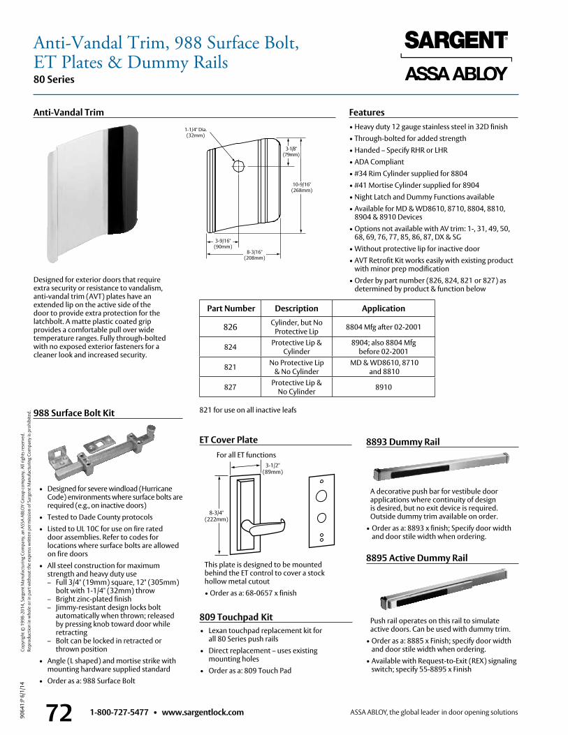
1-800-727-5477 • www.sargentlock.com72
80 Series
9064
1:P
6/1/
14
Copy
right
© 1
998-
2014
, Sar
gent
Man
ufac
turin
g Co
mpa
ny, a
n AS
SA A
BLO
Y G
roup
com
pany
. All
right
s res
erve
d.
Re
prod
uctio
n in
who
le o
r in
part
with
out t
he e
xpre
ss w
ritte
n pe
rmis
sion
of S
arge
nt M
anuf
actu
ring
Com
pany
is p
rohi
bite
d.
8893 Dummy Rail
A decorative push bar for vestibule door applications where continuity of design is desired, but no exit device is required . Outside dummy trim available on order .
• Order as a: 8893 x finish; Specify door width and door stile width when ordering .
8895 Active Dummy Rail
Push rail operates on this rail to simulate active doors . Can be used with dummy trim .
• Order as a: 8885 x Finish; specify door width and door stile width when ordering .
• Available with Request-to-Exit (REX) signaling switch; specify 55-8895 x Finish
ET Cover Plate
This plate is designed to be mounted behind the ET control to cover a stock hollow metal cutout• Order as a: 68-0657 x finish
3-1/2" (89mm)
8-3/4" (222mm)
• Lexan touchpad replacement kit for all 80 Series push rails
• Direct replacement – uses existing mounting holes
• Order as a: 809 Touch Pad
809 Touchpad Kit
For all ET functions
Designed for exterior doors that require extra security or resistance to vandalism, anti-vandal trim (AVT) plates have an extended lip on the active side of the door to provide extra protection for the latchbolt . A matte plastic coated grip provides a comfortable pull over wide temperature ranges . Fully through-bolted with no exposed exterior fasteners for a cleaner look and increased security .
3-1/8"(79mm)
10-9/16"(268mm)
8-3/16"(208mm)
3-9/16"(90mm)
1-1/4" Dia .(32mm)
Anti-Vandal Trim
988 Surface Bolt Kit
Features• Heavy duty 12 gauge stainless steel in 32D finish• Through-bolted for added strength• Handed – Specify RHR or LHR• ADA Compliant• #34 Rim Cylinder supplied for 8804 • #41 Mortise Cylinder supplied for 8904• Night Latch and Dummy Functions available• Available for MD & WD8610, 8710, 8804, 8810,
8904 & 8910 Devices• Options not available with AV trim: 1-, 31, 49, 50,
68, 69, 76, 77, 85, 86, 87, DX & SG• Without protective lip for inactive door• AVT Retrofit Kit works easily with existing product
with minor prep modification• Order by part number (826, 824, 821 or 827) as
determined by product & function below
Part Number Description Application
826 Cylinder, but No Protective Lip 8804 Mfg after 02-2001
824 Protective Lip & Cylinder
8904; also 8804 Mfg before 02-2001
821 No Protective Lip & No Cylinder
MD & WD8610, 8710 and 8810
827 Protective Lip & No Cylinder 8910
821 for use on all inactive leafs
• Designed for severe windload (Hurricane Code) environments where surface bolts are
required (e .g ., on inactive doors)• Tested to Dade County protocols• Listed to UL 10C for use on fire rated
door assemblies . Refer to codes for locations where surface bolts are allowed on fire doors
• All steel construction for maximum strength and heavy duty use – Full 3/4" (19mm) square, 12" (305mm) bolt with 1-1/4" (32mm) throw – Bright zinc-plated finish – Jimmy-resistant design locks bolt
automatically when thrown; released by pressing knob toward door while retracting
– Bolt can be locked in retracted or thrown position
• Angle (L shaped) and mortise strike with mounting hardware supplied standard
• Order as a: 988 Surface Bolt
Anti-Vandal Trim, 988 Surface Bolt,ET Plates & Dummy Rails
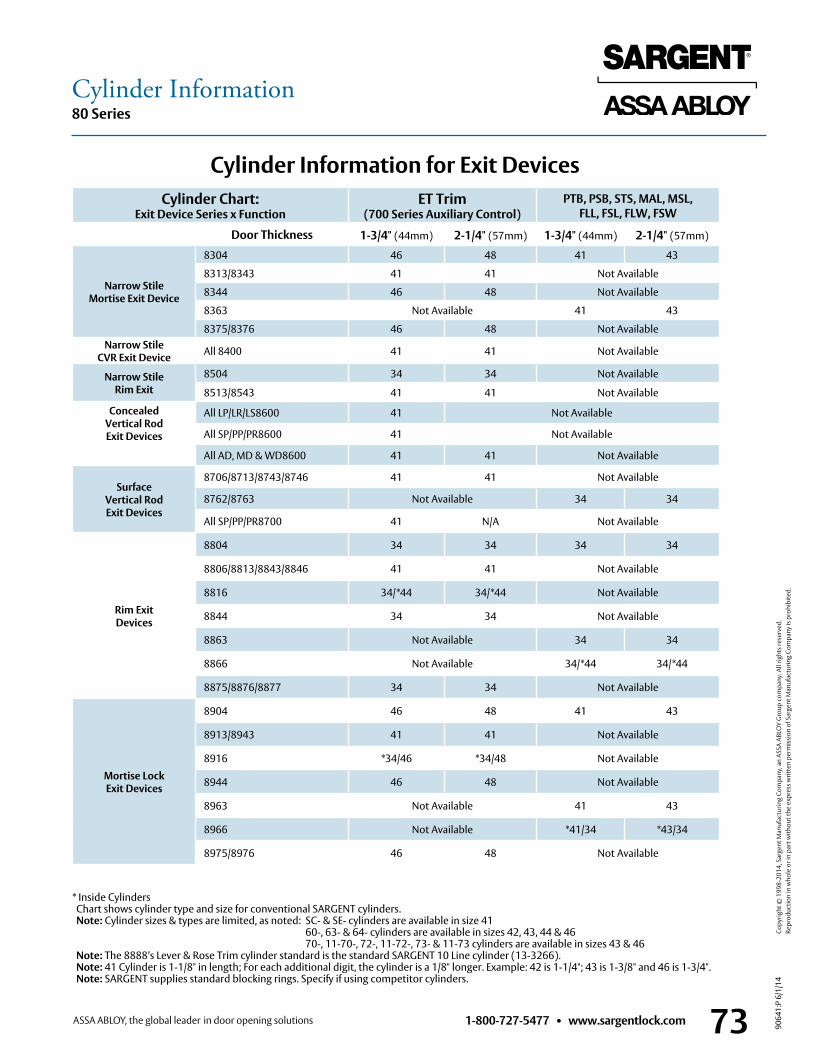
1-800-727-5477 • www.sargentlock.com 73
80 Series
9064
1:P
6/1/
14
Copy
right
© 1
998-
2014
, Sar
gent
Man
ufac
turin
g Co
mpa
ny, a
n AS
SA A
BLO
Y G
roup
com
pany
. All
right
s res
erve
d.
Re
prod
uctio
n in
who
le o
r in
part
with
out t
he e
xpre
ss w
ritte
n pe
rmis
sion
of S
arge
nt M
anuf
actu
ring
Com
pany
is p
rohi
bite
d.
Cylinder Information
Cylinder Information for Exit DevicesCylinder Chart:
Exit Device Series x FunctionET Trim
(700 Series Auxiliary Control)PTB, PSB, STS, MAL, MSL,
FLL, FSL, FLW, FSW
Door Thickness 1-3/4" (44mm) 2-1/4" (57mm) 1-3/4" (44mm) 2-1/4" (57mm)
Narrow StileMortise Exit Device
8304 46 48 41 43
8313/8343 41 41 Not Available
8344 46 48 Not Available
8363 Not Available 41 43
8375/8376 46 48 Not AvailableNarrow Stile
CVR Exit Device All 8400 41 41 Not Available
Narrow StileRim Exit
8504 34 34 Not Available
8513/8543 41 41 Not Available
ConcealedVertical RodExit Devices
All LP/LR/LS8600 41 Not Available
All SP/PP/PR8600 41 Not Available
All AD, MD & WD8600 41 41 Not Available
SurfaceVertical RodExit Devices
8706/8713/8743/8746 41 41 Not Available
8762/8763 Not Available 34 34
All SP/PP/PR8700 41 N/A Not Available
Rim ExitDevices
8804 34 34 34 34
8806/8813/8843/8846 41 41 Not Available
8816 34/*44 34/*44 Not Available
8844 34 34 Not Available
8863 Not Available 34 34
8866 Not Available 34/*44 34/*44
8875/8876/8877 34 34 Not Available
Mortise LockExit Devices
8904 46 48 41 43
8913/8943 41 41 Not Available
8916 *34/46 *34/48 Not Available
8944 46 48 Not Available
8963 Not Available 41 43
8966 Not Available *41/34 *43/34
8975/8976 46 48 Not Available
* Inside Cylinders Chart shows cylinder type and size for conventional SARGENT cylinders . Note: Cylinder sizes & types are limited, as noted: SC- & SE- cylinders are available in size 41
60-, 63- & 64- cylinders are available in sizes 42, 43, 44 & 46 70-, 11-70-, 72-, 11-72-, 73- & 11-73 cylinders are available in sizes 43 & 46
Note: The 8888’s Lever & Rose Trim cylinder standard is the standard SARGENT 10 Line cylinder (13-3266) . Note: 41 Cylinder is 1-1/8" in length; For each additional digit, the cylinder is a 1/8" longer . Example: 42 is 1-1/4"; 43 is 1-3/8" and 46 is 1-3/4" . Note: SARGENT supplies standard blocking rings . Specify if using competitor cylinders .
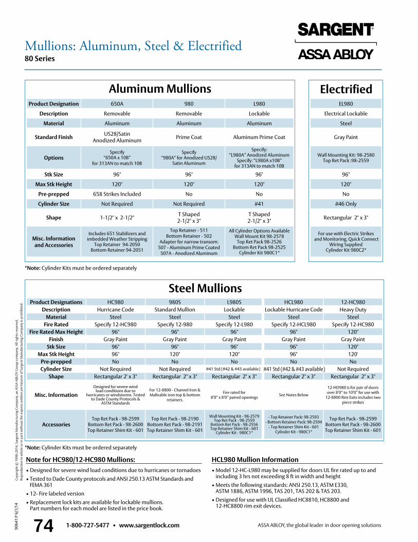
1-800-727-5477 • www.sargentlock.com74
80 Series
9064
1:P
6/1/
14
Copy
right
© 1
998-
2014
, Sar
gent
Man
ufac
turin
g Co
mpa
ny, a
n AS
SA A
BLO
Y G
roup
com
pany
. All
right
s res
erve
d.
Re
prod
uctio
n in
who
le o
r in
part
with
out t
he e
xpre
ss w
ritte
n pe
rmis
sion
of S
arge
nt M
anuf
actu
ring
Com
pany
is p
rohi
bite
d. Product Designations HC980 980S L980SDescription Hurricane Code Standard Mullion Lockable
Material Steel Steel SteelFire Rated Specify 12-HC980 Specify 12-980 Specify 12-L980
Fire Rated Max Height 96" 96" 96"Finish Gray Paint Gray Paint Gray Paint
Stk Size 96" 96" 96"Max Stk Height 96" 120" 120"
Pre-prepped No No NoCylinder Size Not Required Not Required #41 Std (#42 & #43 available)
Shape Rectangular 2' x 3" Rectangular 2" x 3" Rectangular 2" x 3"
Misc. InformationDesigned for severe wind
load conditions due tohurricanes or windstorms . Tested
to Dade County Protocols & ASTM Standards
For 12-8800 - Channel Iron & Malleable iron top & bottom
retainers .
Fire rated for 8’0” x 8’0” paired openings
AccessoriesTop Ret Pack - 98-2599
Bottom Ret Pack - 98-2600Top Retainer Shim Kit - 601
Top Ret Pack - 98-2190Bottom Ret Pack - 98-2191Top Retainer Shim Kit - 601
Wall Mounting Kit - 98-2579Top Ret Pack - 98-2559
Bottom Ret Pack - 98-2556Top Retainer Shim Kit - 601
Cylinder Kit - 980C1*
12-HC980Heavy Duty
SteelSpecify 12-HC980
120"Gray Paint
120"120'No
Not RequiredRectangular 2" x 3"
12-HD980 is for pair of doors over 8’0” to 10’0” for use with
12-8800 Rim Exits includes two piece strikes
Top Ret Pack - 98-2599Bottom Ret Pack - 98-2600Top Retainer Shim Kit - 601
Aluminum Mullions
Steel Mullions
Note for HC980/12-HC980 Mullions:• Designed for severe wind load conditions due to hurricanes or tornadoes• Tested to Dade County protocols and ANSI 250 .13 ASTM Standards and
FEMA 361• 12- Fire labeled version• Replacement lock kits are available for lockable mullions .
Part numbers for each model are listed in the price book .
HCL980 Mullion Information• Model 12-HC-L980 may be supplied for doors UL fire rated up to and
including 3 hrs not exceeding 8 ft in width and height• Meets the following standards: ANSI 250 .13, ASTM E330,
ASTM 1886, ASTM 1996, TAS 201, TAS 202 & TAS 203 .• Designed for use with UL Classified HC8810, HC8800 and
12-HC8800 rim exit devices .
Product Designation 650A 980 L980
Description Removable Removable Lockable
Material Aluminum Aluminum Aluminum
Standard Finish US28/SatinAnodized Aluminum Prime Coat Aluminum Prime Coat
OptionsSpecify
“650A x 10B” for 313AN to match 10B
Specify “980A” for Anodized US28/
Satin Aluminum
Specify: “L980A” Anodized Aluminum
Specify: “L980A x10B” for 313AN to match 10B
Stk Size 96" 96" 96"
Max Stk Height 120" 120" 120"
Pre-prepped 658 Strikes Included No No
Cylinder Size Not Required Not Required #41
Shape 1-1/2" x 2-1/2" T Shaped 2-1/2" x 3"
T Shaped 2-1/2" x 3"
Misc. Information and Accessories
Includes 651 Stabilizers and imbedded Weather Stripping
Top Retainer 94-2050 Bottom Retainer 94-2051
Top Retainer - 511Bottom Retainer - 502
Adapter for narrow transom:507 - Aluminum Prime Coated
507A - Anodized Aluminum
All Cylinder Options AvailableWall Mount Kit 98-2578
Top Ret Pack 98-2526 Bottom Ret Pack 98-2525
Cylinder Kit 980C1*
EL980
Electrical Lockable
Steel
Gray Paint
Wall Mounting Kit: 98-2580 Top Ret Pack :98-2559
96"
120"
No
#46 Only
Rectangular 2" x 3"
For use with Electric Strikes and Monitoring, Quick Connect
Wiring Supplied Cylinder Kit 980C2*
Electrified
HCL980
SteelSpecify 12-HCL980
96"Gray Paint
96"96"No
Rectangular 2" x 3"
See Notes Below
- Top Retainer Pack: 98-2593 - Bottom Retainer Pack: 98-2594
- Top Retainer Shim Kit - 601 Cylinder Kit - 980C1*
Lockable Hurricane Code
#41 Std (#42 & #43 available)
*Note: Cylinder Kits must be ordered separately
*Note: Cylinder Kits must be ordered separately
Mullions: Aluminum, Steel & Electrified
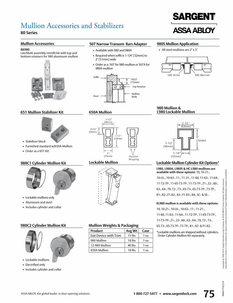
1-800-727-5477 • www.sargentlock.com 75
80 Series
9064
1:P
6/1/
14
Copy
right
© 1
998-
2014
, Sar
gent
Man
ufac
turin
g Co
mpa
ny, a
n AS
SA A
BLO
Y G
roup
com
pany
. All
right
s res
erve
d.
Re
prod
uctio
n in
who
le o
r in
part
with
out t
he e
xpre
ss w
ritte
n pe
rmis
sion
of S
arge
nt M
anuf
actu
ring
Com
pany
is p
rohi
bite
d.
Mullion Accessories and Stabilizers
Lockable Mullion Cylinder Kit Options*L980, L980A, L980S & HC-L980 mullions are available with these options: 10, 10-21-,
10-UL-, 10-63-, 11-, 11-21-, 11-60, 11-63-, 11-64-,
11-72-7P-, 11-65-73-7P-, 11-73-7P-, 21-, 22-, 60-,
63-, 64-, 70, 72-, 73-, 65-73-, 65-73-7P-, 73-7P-,
81-, 82-, F1-82-, 83-, F1-83-, 84-, SC- & SE- .
EL980 mullion is available with these options:
10, 10-21-, 10-UL-, 10-63-, 11-, 11-21-,
11-60, 11-63-, 11-64-, 11-72-7P-, 11-65-73-7P-,
11-73-7P-, 21-, 22-, 60-, 63-, 64-, 70, 72-, 73-,
65-73-, 65-73-7P-, 73-7P-, 81-, 82- & F1-82- .
* Lockable mullions are shipped without cylinders . Order Cylinder Mullion Kit separately .
Mullion AccessoriesRK980 Latchbolt assembly retrofit kit with top and bottom retainers for 980 aluminum mullion
Lockable Mullion
980 Mullion & L980 Lockable Mullion650A Mullion
980S Mullion Application • All steel mullions are 2" x 3"
651 Mullion Stabilizer Kit
• Stabilizer block • Furnished standard w/650A Mullion • Order as a 651 Kit
507 Narrow Transom Bars Adapter • Available with 980 and 980A
• Required when soffit is 1-1/4" (32mm) to 2" (51mm) wide
• Order as a: 507 for 980 mullion or 507A for 980A mullion
Top Retainer
Mullion Body
Soffit
Door
19/32" (15mm)
980C1 Cylinder Mullion Kit
• Lockable mullions only • Aluminum and steel • Includes cylinder and collar
980C2 Cylinder Mullion Kit
• Lockable mullions • Electrified only • Includes cylinder and collar
Product Avg Wt CaseExit Device with Trim 15 lbs 1 ea980 Mullion 18 lbs 1 ea12-980 Mullion 40 lbs 1 ea650A Mullion 18 lbs 1 ea
Mullion Weights & Packaging
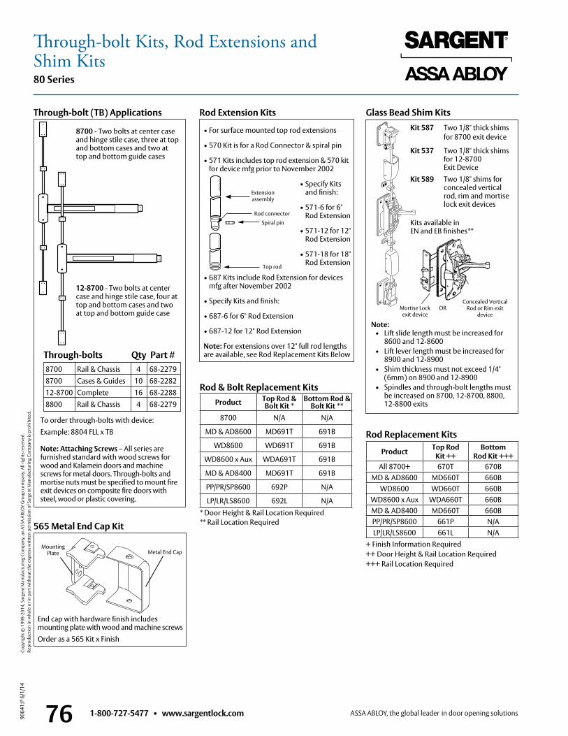
1-800-727-5477 • www.sargentlock.com76
80 Series
9064
1:P
6/1/
14
Copy
right
© 1
998-
2014
, Sar
gent
Man
ufac
turin
g Co
mpa
ny, a
n AS
SA A
BLO
Y G
roup
com
pany
. All
right
s res
erve
d.
Re
prod
uctio
n in
who
le o
r in
part
with
out t
he e
xpre
ss w
ritte
n pe
rmis
sion
of S
arge
nt M
anuf
actu
ring
Com
pany
is p
rohi
bite
d.
Rod Extension Kits
• For surface mounted top rod extensions
• 570 Kit is for a Rod Connector & spiral pin
• 571 Kits includes top rod extension & 570 kit for device mfg prior to November 2002
• Specify Kits and finish:
• 571-6 for 6" Rod Extension
• 571-12 for 12" Rod Extension
• 571-18 for 18" Rod Extension
• 687 Kits include Rod Extension for devices mfg after November 2002
• Specify Kits and finish:
• 687-6 for 6" Rod Extension
• 687-12 for 12" Rod Extension
Note: For extensions over 12" full rod lengths are available, see Rod Replacement Kits Below
Glass Bead Shim KitsKit 587 Two 1/8" thick shims
for 8700 exit device
Kit 537 Two 1/8" thick shims for 12-8700 Exit Device
Kit 589 Two 1/8" shims for concealed vertical rod, rim and mortise lock exit devices
Kits available in EN and EB finishes**
565 Metal End Cap Kit
End cap with hardware finish includes mounting plate with wood and machine screws
Order as a 565 Kit x Finish
Rod Replacement KitsTo order through-bolts with device:Example: 8804 FLL x TB Note: Attaching Screws – All series are furnished standard with wood screws for wood and Kalamein doors and machine screws for metal doors . Through-bolts and mortise nuts must be specified to mount fire exit devices on composite fire doors with steel, wood or plastic covering .
Through-bolt (TB) Applications
8700 - Two bolts at center case and hinge stile case, three at top and bottom cases and two at top and bottom guide cases
12-8700 - Two bolts at center case and hinge stile case, four at top and bottom cases and two at top and bottom guide case
Metal End CapMounting
Plate
Note: • Lift slide length must be increased for
8600 and 12-8600 • Lift lever length must be increased for 8900 and 12-8900 • Shim thickness must not exceed 1/4"
(6mm) on 8900 and 12-8900 • Spindles and through-bolt lengths must
be increased on 8700, 12-8700, 8800, 12-8800 exits
Mortise Lock exit device
Concealed Vertical Rod or Rim exit
deviceOR
8700 Rail & Chassis 4 68-2279 8700 Cases & Guides 10 68-2282 12-8700 Complete 16 68-2288 8800 Rail & Chassis 4 68-2279
Through-bolts Qty Part #
Product Top Rod Kit ++
BottomRod Kit +++
All 8700+ 670T 670BMD & AD8600 MD660T 660B
WD8600 WD660T 660BWD8600 x Aux WDA660T 660BMD & AD8400 MD660T 660BPP/PR/SP8600 661P N/ALP/LR/LS8600 661L N/A
+ Finish Information Required++ Door Height & Rail Location Required+++ Rail Location Required
* Door Height & Rail Location Required** Rail Location Required
Product Top Rod & Bolt Kit *
Bottom Rod & Bolt Kit **
8700 N/A N/A
MD & AD8600 MD691T 691B
WD8600 WD691T 691B
WD8600 x Aux WDA691T 691B
MD & AD8400 MD691T 691B
PP/PR/SP8600 692P N/A
LP/LR/LS8600 692L N/A
Rod & Bolt Replacement Kits
Extension assembly
Rod connector
Spiral pin
Top rod
Through-bolt Kits, Rod Extensions and Shim Kits
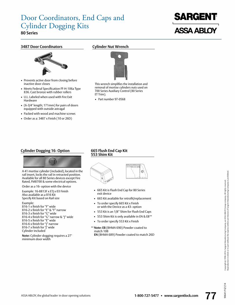
1-800-727-5477 • www.sargentlock.com 77
80 Series
9064
1:P
6/1/
14
Copy
right
© 1
998-
2014
, Sar
gent
Man
ufac
turin
g Co
mpa
ny, a
n AS
SA A
BLO
Y G
roup
com
pany
. All
right
s res
erve
d.
Re
prod
uctio
n in
who
le o
r in
part
with
out t
he e
xpre
ss w
ritte
n pe
rmis
sion
of S
arge
nt M
anuf
actu
ring
Com
pany
is p
rohi
bite
d.
Door Coordinators, End Caps and Cylinder Dogging Kits
3487 Door Coordinators
• Prevents active door from closing before inactive door closes
• Meets Federal Specification FF-H-106a Type 836 . Cast bronze with rubber rollers
• U .L . Labeled when used with Fire Exit Hardware
• (6-3/4" length; 171mm) for pairs of doors equipped with outside astragal
• Packed with wood and machine screws• Order as a: 3487 x Finish (10 or 26D)
Cylinder Nut Wrench
This wrench simplifies the installation and removal of mortise cylinders nuts used on 700 Series Auxiliary Control (80 Series ET Trim) .• Part number 97-0568
Cylinder Dogging 16- Option
A 41 mortise cylinder (included), located in the rail insert, locks the rail in retracted position . Available for all 80 Series devices except Fire Rated, FM8700 & some electrical options .Order as a 16- option with the deviceExample: 16-8813F x ETJ x 03 Finish Also available as a 816 Kit Specify Kit based on Rail sizeExample: 816-1 x finish for “F” wide 816-2 x finish for “E” & “F” narrow 816-3 x finish for “G” wide 816-4 x finish for “G” narrow & “J” wide 816-5 x finish for “E” wide 816-6 x finish for “J” narrow 816-7 x finish for "J" wide Cylinder includedNote: Cylinder dogging requires a 27" minimum door width
665 Flush End Cap Kit 553 Shim Kit
• 665 Kit is Flush End Cap for 80 Series exit device
• 665 Kit available for retrofit/replacement• To order specify 665 Kit x Finish or with the Device as a 43- option• 553 Kit is an 1/8” Shim for Flush End Caps• 553 Shim Kit is only available in EN & EB**• To order specify 553 Kit x Finish
** Note: EB (BHMA 690) Powder coated to match 10B EN (BHMA 689) Powder coated to match 26D
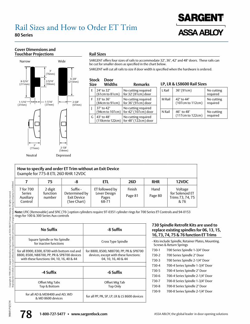
1-800-727-5477 • www.sargentlock.com78
80 Series
9064
1:P
6/1/
14
Copy
right
© 1
998-
2014
, Sar
gent
Man
ufac
turin
g Co
mpa
ny, a
n AS
SA A
BLO
Y G
roup
com
pany
. All
right
s res
erve
d.
Re
prod
uctio
n in
who
le o
r in
part
with
out t
he e
xpre
ss w
ritte
n pe
rmis
sion
of S
arge
nt M
anuf
actu
ring
Com
pany
is p
rohi
bite
d.
Rail Sizes and How to Order ET Trim
Cover Dimensions and Touchbar Projections
Narrow Wide
Neutral Depressed
3" (77mm)
2-5/16" (59mm)
2-1/8" (54mm)
1-1/16" (27mm)
1-7/16" (37mm)
8-5/16" (211mm)
3" (76mm)
8-3/8" (213mm)
2-5/8" (67mm)
L Rail 36" (91cm) No cutting required M Rail 42" to 44" No cutting (107cm to 112cm) required N Rail 46" to 48" No cutting (117cm to 122cm) required
Rail SizesSARGENT offers four sizes of rails to accommodate 32", 36", 42" and 48" doors . These rails can be cut for smaller doors as specified in the chart below .SARGENT will cut all rails to size if door width is specified when the hardware is ordered .
E 24" to 32" No cutting required (61cm to 81cm) for 32' (81cm) door F 33" to 36" No cutting required (84cm to 91cm) for 36" (91cm) door J 37" to 42" No cutting required (94cm to 107cm) for 42" (107cm) door G 43" to 48" No cutting required (110cm to 122cm) for 48" (122cm) door
Stock Door Size Widths Remarks LP, LR & LS8600 Rail Sizes
No Suffix -8 Suffix
Square Spindle or No Spindle for inactive functions Cross Type Spindle
for all 8900, 8300, 8700 with bottom rod and 8800, 8500, NB8700, PP, PR & SP8700 devices
with these functions: 04, 10, 16, 40 & 44
for 8800, 8500, NB8700, PP, PR & SP8700 devices, except with these functions:
04, 10, 16, 40 & 44
-4 Suffix -6 Suffix
Offset Mtg Tabs Top & Bottom
Offset Mtg TabTop Only
for all AD & MD8400 and AD, WD & MD 8600 devices for all PP, PR, SP, LP, LR & LS 8600 devices
How to specify and order ET Trim without an Exit Device Example for 775-8 ETL 26D RHR 12VDC
7 75 -8 ETL 26D RHR 12VDC
7 for 700 Series
Auxiliary Control
2 digit function number
Suffix - Determined by
Exit Device (See Chart)
ET followed by Lever Design
Pages 68-71
Finish
Page 81
Hand
Page 80
Voltage for Solenoid ET Trims 73, 74, 75
& 76
Note: LFIC (Removable) and SFIC (70-) option cylinders require 97-0351 cylinder rings for 700 Series ET Controls and 94-0153 rings for 100 & 300 Series Aux controls
730 Spindle Retrofit Kits are used to replace existing spindles for 06, 13, 15, 16, 73, 74, 75 & 76 function ET Trims- Kits include Spindle, Retainer Plates, Mounting .
Screws & Return Springs730-1 700 Series Spindle 1-3/4" Door730-2 700 Series Spindle 2" Door730-3 700 Series Spindle 2-1/4" Door730-4 700-4 Series Spindle 1-3/4" Door730-5 700-4 Series Spindle 2" Door 730-6 700-4 Series Spindle 2-1/4" Door730-7 700-8 Series Spindle 1-3/4" Door730-8 700-8 Series Spindle 2" Door730-9 700-8 Series Spindle 2-1/4" Door
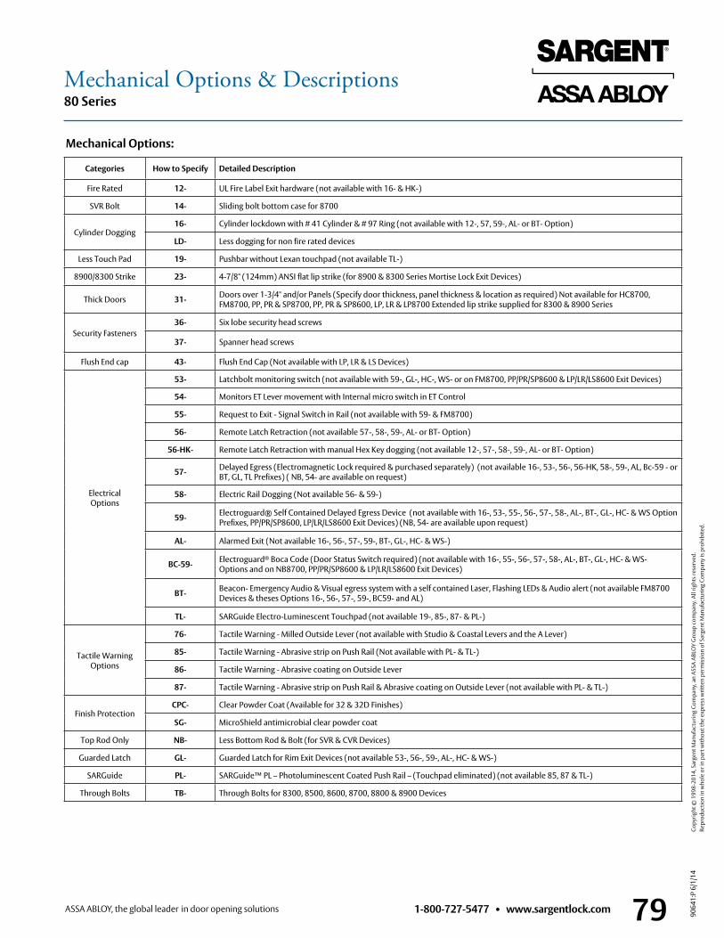
1-800-727-5477 • www.sargentlock.com 79
80 Series
9064
1:P
6/1/
14
Copy
right
© 1
998-
2014
, Sar
gent
Man
ufac
turin
g Co
mpa
ny, a
n AS
SA A
BLO
Y G
roup
com
pany
. All
right
s res
erve
d.
Re
prod
uctio
n in
who
le o
r in
part
with
out t
he e
xpre
ss w
ritte
n pe
rmis
sion
of S
arge
nt M
anuf
actu
ring
Com
pany
is p
rohi
bite
d.
Mechanical Options & Descriptions
Mechanical Options:
Categories How to Specify Detailed Description
Fire Rated 12- UL Fire Label Exit hardware (not available with 16- & HK-)
SVR Bolt 14- Sliding bolt bottom case for 8700
Cylinder Dogging16- Cylinder lockdown with # 41 Cylinder & # 97 Ring (not available with 12-, 57, 59-, AL- or BT- Option)
LD- Less dogging for non fire rated devices
Less Touch Pad 19- Pushbar without Lexan touchpad (not available TL-)
8900/8300 Strike 23- 4-7/8" (124mm) ANSI flat lip strike (for 8900 & 8300 Series Mortise Lock Exit Devices)
Thick Doors 31- Doors over 1-3/4" and/or Panels (Specify door thickness, panel thickness & location as required) Not available for HC8700, FM8700, PP, PR & SP8700, PP, PR & SP8600, LP, LR & LP8700 Extended lip strike supplied for 8300 & 8900 Series
Security Fasteners36- Six lobe security head screws
37- Spanner head screws
Flush End cap 43- Flush End Cap (Not available with LP, LR & LS Devices)
Electrical Options
53- Latchbolt monitoring switch (not available with 59-, GL-, HC-, WS- or on FM8700, PP/PR/SP8600 & LP/LR/LS8600 Exit Devices)
54- Monitors ET Lever movement with Internal micro switch in ET Control
55- Request to Exit - Signal Switch in Rail (not available with 59- & FM8700)
56- Remote Latch Retraction (not available 57-, 58-, 59-, AL- or BT- Option)
56-HK- Remote Latch Retraction with manual Hex Key dogging (not available 12-, 57-, 58-, 59-, AL- or BT- Option)
57- Delayed Egress (Electromagnetic Lock required & purchased separately) (not available 16-, 53-, 56-, 56-HK, 58-, 59-, AL, Bc-59 - or BT, GL, TL Prefixes) ( NB, 54- are available on request)
58- Electric Rail Dogging (Not available 56- & 59-)
59- Electroguard® Self Contained Delayed Egress Device (not available with 16-, 53-, 55-, 56-, 57-, 58-, AL-, BT-, GL-, HC- & WS Option Prefixes, PP/PR/SP8600, LP/LR/LS8600 Exit Devices) (NB, 54- are available upon request)
AL- Alarmed Exit (Not available 16-, 56-, 57-, 59-, BT-, GL-, HC- & WS-)
BC-59- Electroguard® Boca Code (Door Status Switch required) (not available with 16-, 55-, 56-, 57-, 58-, AL-, BT-, GL-, HC- & WS- Options and on NB8700, PP/PR/SP8600 & LP/LR/LS8600 Exit Devices)
BT- Beacon- Emergency Audio & Visual egress system with a self contained Laser, Flashing LEDs & Audio alert (not available FM8700 Devices & theses Options 16-, 56-, 57-, 59-, BC59- and AL)
TL- SARGuide Electro-Luminescent Touchpad (not available 19-, 85-, 87- & PL-)
Tactile Warning Options
76- Tactile Warning - Milled Outside Lever (not available with Studio & Coastal Levers and the A Lever)
85- Tactile Warning - Abrasive strip on Push Rail (Not available with PL- & TL-)
86- Tactile Warning - Abrasive coating on Outside Lever
87- Tactile Warning - Abrasive strip on Push Rail & Abrasive coating on Outside Lever (not available with PL- & TL-)
Finish ProtectionCPC- Clear Powder Coat (Available for 32 & 32D Finishes)
SG- MicroShield antimicrobial clear powder coat
Top Rod Only NB- Less Bottom Rod & Bolt (for SVR & CVR Devices)
Guarded Latch GL- Guarded Latch for Rim Exit Devices (not available 53-, 56-, 59-, AL-, HC- & WS-)
SARGuide PL- SARGuide™ PL – Photoluminescent Coated Push Rail – (Touchpad eliminated) (not available 85, 87 & TL-)
Through Bolts TB- Through Bolts for 8300, 8500, 8600, 8700, 8800 & 8900 Devices
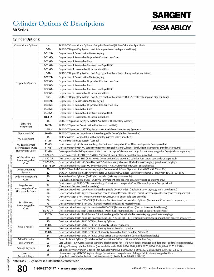
1-800-727-5477 • www.sargentlock.com80
80 Series
9064
1:P
6/1/
14
Copy
right
© 1
998-
2014
, Sar
gent
Man
ufac
turin
g Co
mpa
ny, a
n AS
SA A
BLO
Y G
roup
com
pany
. All
right
s res
erve
d.
Re
prod
uctio
n in
who
le o
r in
part
with
out t
he e
xpre
ss w
ritte
n pe
rmis
sion
of S
arge
nt M
anuf
actu
ring
Com
pany
is p
rohi
bite
d.
Cylinder Options & Descriptions
Cylinder Options:
Conventional Cylinder - SARGENT Conventional Cylinders Supplied Standard (Unless Otherwise Specified)
Degree Key System
DG1- SARGENT Degree Key System Level 1 (bump resistant with patented keys)
DG1-21- Degree Level 1 Construction Master Keying
DG1-60- Degree Level 1 Removable Disposable Construction Core
DG1-63- Degree Level 1 Removable Core
DG1-64- Degree Level 1 Removable Construction Keyed LFIC
DG1-65- Degree Level 1 Unassembled/Uncombined Core
DG2- SARGENT Degree Key System Level 2 (geographically exclusive; bump and pick resistant)
DG2-21- Degree Level 2 Construction Master Keying
DG2-60- Degree Level 2 Removable Disposable Construction Core
DG2-63- Degree Level 2 Removable Core
DG2-64- Degree Level 2 Removable Construction Keyed LFIC
DG2-65- Degree Level 2 Unassembled/Uncombined Core
DG3- SARGENT Degree Key System Level 3 (geographically exclusive; UL437 certified; bump and pick resistant)
DG3-21- Degree Level 3 Construction Master Keying
DG3-60- Degree Level 3 Removable Disposable Construction Core
DG3-63- Degree Level 3 Removable Core
DG3-64- Degree Level 3 Removable Construction Keyed LFIC
DG3-65 Degree Level 3 Unassembled/Uncombined Core
Signature Key System
10- SARGENT Signature Key System (Not Available with other Key Systems)
10-21- SARGENT Signature Construction Key System (Lost Ball)
10UL- SARGENT Signature UL437 Key System (Not Available with other Key Systems)
Signature- LFIC 10-63- SARGENT Signature Large Format Interchangeable Core Cylinder (Removable)
XC- Key System11- XC Key System (Not available with other Key systems unless specified)
11-21- XC- Construction Key System (Lost Ball)
XC- Large FormatInterchangeable Core
(Removable Core)
11-60- Device to accept XC- Permanent Large Format Interchangeable Core, Disposable plastic Core- provided11-63- Device provided with XC- Large Format Interchangeable Core Cylinder - (Includes masterkeying, grand masterkeying)11-64- Device provided with Keyed construction core to accept XC- Permanent Large Format Interchangeable Core (ordered separately)
XC- Small FormatInterchangeable
Core
11-70-7P- Device to accept XC- SFIC ( 7-Pin) XC- Permanent Cores, plastic disposable core provided 11-72-7P- Device to accept XC- SFIC (7-Pin Keyed Construction Core provided) cylinder Permanent core ordered separately 11-73-7P- Device provided with XC- Small Format 7-Pin interchangeable core (Includes masterkeying, grand masterkeying)
11-65-73-7P- Device provided to accept XC- Uncombinated 7-Pin SFIC (Permanent) Core - (Packed Loose) Construction Key
Systems21- SARGENT Lost Ball Construction Keying for Conventional, XC and Signature Series (N/A with 63- or 73-)22- SARGENT Construction Split Key System for Conventional Cylinders (Existing Systems Only) (N/A with 10-, 11-, 63- or 73-)
Old Style Removable Core
51- Removable Core Cylinder (Old Style) provided (existing systems only)52- Removable Construction Core (Old Style) Permanent core ordered separately (existing systems only)
Large Format Interchangeable Core
(Removable Core)
60- Device to accept SARGENT Permanent Large Format Interchangeable Core, Disposable plastic Core provided (Permanent Cores ordered separately)
63- Device provided with Large Format Interchangeable Core Cylinder - (Includes masterkeying, grand masterkeying)64- Device provided with Keyed construction core to accept Permanent Large Format Interchangeable Core (ordered separately)
Small Format Interchangeable
Core
70- Device to accept 6- or 7-Pin SFIC Permanent Cores, plastic disposable core provided 72- Device to accept 6- or 7-Pin SFIC (6-Pin Keyed Construction Core provided) Cylinder (Permanent Core ordered separately)73- Device provided with 6-Pin SFIC (Includes masterkeying, grand masterkeying)
65-73- Device provided to accept Uncombinated 6-Pin SFIC (Permanent) Core - (Packed Loose for field keying)65-73-7P- Device provided to accept Uncombinated 7-Pin SFIC (Permanent) Core - (Packed Loose for field keying)
73-7P- Device provided with Small Format 7-Pin Interchangeable Core (Includes masterkeying, grand masterkeying)
Keso & Keso F1
81- Device provided with housings to accept Keso (83) & Keso F1 (F1-83-) removable cores . (Permanent Cores ordered separately) 82- Device provided with SARGENT Keso Security Cylinder
F1-82- Device provided with SARGENT Keso F1 Security Cylinder (Patented)83- Device provided with SARGENT Keso Security Removable Core cylinder
F1-83- Device provided with SARGENT Keso F1 Security Removable Core cylinder (Patented) 84- Device provided with SARGENT Keso Construction Cores (Permanent Cores ordered separately)
Added Security BR- Bump Resistant Cylinder (Available with Conventional & Conventional XC Cylinders Only)Less Cylinder LC- Less Cylinder - SARGENT supplies standard blocking rings for 1-1/8" Cylinders (For longer cylinders order collars/rings separately)
Schlage KeywaysSC- Schlage C keyway cylinder, 0 bitted (not available with: 8904, 8916, 8944, 8975, 8976, 8866, 8304, 8344, 8375 & 8376)SE- Schlage E keyway cylinder, 0 bitted (not available with: 8904, 8916, 8944, 8975, 8976, 8866, 8304, 8344, 8375 & 8376)
Lever to Accept Schlage SF- L Lever to accept MEDECO KeyMark Large Format Interchangeable and Schlage Full Size Interchangeable Core
(Supplied Less Cylinder, but with tailpiece needed) (Available for 88-KLL & 88-CLL)
Note: For V-10 Cylinders and information, contact ASSA
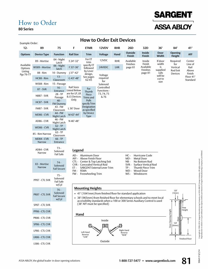
1-800-727-5477 • www.sargentlock.com 81
80 Series
9064
1:P
6/1/
14
Copy
right
© 1
998-
2014
, Sar
gent
Man
ufac
turin
g Co
mpa
ny, a
n AS
SA A
BLO
Y G
roup
com
pany
. All
right
s res
erve
d.
Re
prod
uctio
n in
who
le o
r in
part
with
out t
he e
xpre
ss w
ritte
n pe
rmis
sion
of S
arge
nt M
anuf
actu
ring
Com
pany
is p
rohi
bite
d.
How to Order
12- 89 75 F ETMR 12VDV RHR 26D 32D 36" 84" 41"
Options Device Type Function Rail Size Trim Voltage Hand Outside Finish
Inside Finish
Door Width
OpeningHeight AFF
AvailableOptionsListing
Pgs 76-77
89 - Mortise 04 - NightLatch E 24"-32"
For ETtrim
specify ETfollowedby Leverdesign,
See pages62-65
ForThumbPiece
Trims andPulls
specify TrimDesignation as specifiedby Device
Type
12VDC
24V0DC
Voltagerequired
forSolenoid
Controlled Functions -73, 74, 75
& 76
RHR AvailableFinishes page 81
Requiredfor
VerticalRod ExitDevices
CenterLine of
RailAboveFinish
Floor 41"Standard
WS89 - Mortise 06 - Nightlatch F 33"-36" LHR
88 - Rim 10 - Dummy J 37"-42"
HC88 - Rim 13 -Classroom G 43"-48"
WS88 - Rim 15 - PassageRail Sizes
Listed Beloware for LP, LR& LS Devices
Only
87 - SVR 16 -Entrance
NB87 - SVR 28 - TPPassage
HC87 - SVR 40 -FW Dummy
FM87 - SVR 43 - FWClassroom L 36" Door
MD86 - CVR 44 - FW Night Latch M 42"-44"
AD86 - CVR 46 - FW Night Latch N 46"-48"
WD86 - CVR 62 - TP Night Latch
85 - Rim Narrow 63 - TPClassroom
MD84 - CVR Narrow
66 - TPEntrance
AD84 - CVRNarrow
73 - SolenoidFail Safe
83 - Mortise Narrow
74 - Solenoid
Fail Secure
PP87 - CTL SVR
75 - SolenoidFail Safe
w/Cyl
PR87 - CTL SVR
76 - Solenoid
Fail Securew/Cyl
SP87 - CTL SVR
PP86 - CTL CVR
PR86 - CTL CVR
SP86 - CTL CVR
LP86 - CTL CVR
LR86 - CTL CVR
LS86 - CTL CVR
If doorwidth
issupplied
railswill becut to
size
Inside Finish
AvailableFinishespage 81
LegendAD - Aluminum Door HC - Hurricane Code AFF - Above Finish Floor MD - Metal Door CTL - Center & Top Latching Exit NB - No Bottom Rod CVR - Concealed Vertical Rod SVR - Surface Vertical Rod ET - SARGENT External Lever Trim TP - Thumb Piece Trim FM - FEMA WD - Wood Door FW - Freewheeling Trim WS - Windstorm
How to Order Exit DevicesExample Order:
Doo
r Ope
ning
Hei
ght
Stop Height
Doo
r
1/4"(6mm)
Finished Floor
Mounting Heights• 41" (1041mm) from finished floor for standard application• 38" (965mm) from finished floor for elementary schools and to meet local
accessibility standards when a 100 or 300 Series Auxiliary Control is used (38" AFF must be specified)
1/8"(3mm)
Hand
Left HandReverse
“LHR”
Right HandReverse “RHR”
Outside
Inside
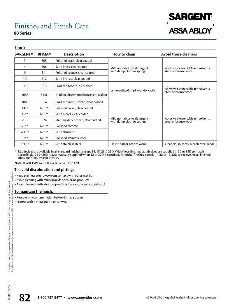
1-800-727-5477 • www.sargentlock.com82
80 Series
9064
1:P
6/1/
14
Copy
right
© 1
998-
2014
, Sar
gent
Man
ufac
turin
g Co
mpa
ny, a
n AS
SA A
BLO
Y G
roup
com
pany
. All
right
s res
erve
d.
Re
prod
uctio
n in
who
le o
r in
part
with
out t
he e
xpre
ss w
ritte
n pe
rmis
sion
of S
arge
nt M
anuf
actu
ring
Com
pany
is p
rohi
bite
d.
Finishes and Finish Care
To avoid discoloration and pitting:• Keep stainless steel away from contact with other metals• Avoid cleaning with mineral acids or chlorine products• Avoid cleaning with abrasive products like sandpaper or steel wool
To maintain the finish:• Remove any contamination before damage occurs• Protect with a metal polish or car wax
** Exit devices are available in all standard finishes, except 14, 15, 26 & 26D . With these finishes, exit devices are supplied in 32 or 32D to match accordingly . 26 or 26D is automatically supplied when 32 or 32D is specified . For nickel finishes, specify 14/32 or 15/32D to receive nickel finished trims and stainless exit devices .
Note: FLW & FSW are NOT available in 32 or 32D
3 605 Polished brass, clear coated
Mild non-abrasive detergent with damp cloth or sponge
Abrasive cleaners, bleach solvents, steel or bronze wool
4 606 Satin brass, clear coated
9 611 Polished bronze, clear coated
10 612 Satin bronze, clear coated
10B 613 Oxidized bronze, oil rubbedLemon oil polished with dry cloth Abrasive cleaners, bleach solvents,
steel or bronze wool10BE 613E Dark oxidized satin bronze, equivalent
10BL 614 Oxidized satin, bronze, clear coated
Mild non-abrasive detergent with damp cloth or sponge
Abrasive cleaners, bleach solvents, steel or bronze wool
14** 618** Polished nickel, clear coated
15** 619** Satin nickel, clear coated
20D 624 Statuary dark bronze, clear coated
26** 625** Polished chrome
26D** 626** Satin chrome
32** 629** Polished stainless steel
32D** 630** Satin stainless steel Plastic pad or bronze wool Cleaners, solvents, bleach, steel wool
Finish
SARGENT# BHMA# Description How to clean Avoid these cleaners
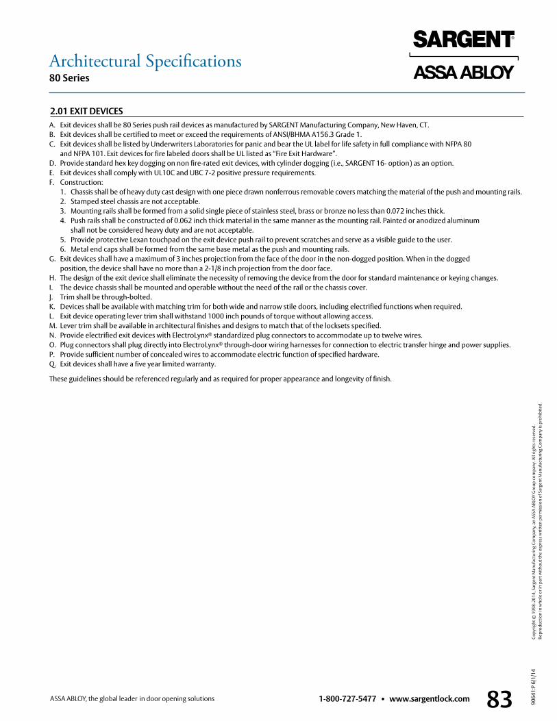
1-800-727-5477 • www.sargentlock.com 83
80 Series
9064
1:P
6/1/
14
Copy
right
© 1
998-
2014
, Sar
gent
Man
ufac
turin
g Co
mpa
ny, a
n AS
SA A
BLO
Y G
roup
com
pany
. All
right
s res
erve
d.
Re
prod
uctio
n in
who
le o
r in
part
with
out t
he e
xpre
ss w
ritte
n pe
rmis
sion
of S
arge
nt M
anuf
actu
ring
Com
pany
is p
rohi
bite
d.
Architectural Specifications
A . Exit devices shall be 80 Series push rail devices as manufactured by SARGENT Manufacturing Company, New Haven, CT .B . Exit devices shall be certified to meet or exceed the requirements of ANSI/BHMA A156 .3 Grade 1 .C . Exit devices shall be listed by Underwriters Laboratories for panic and bear the UL label for life safety in full compliance with NFPA 80
and NFPA 101 . Exit devices for fire labeled doors shall be UL listed as “Fire Exit Hardware” .D . Provide standard hex key dogging on non fire-rated exit devices, with cylinder dogging (i .e ., SARGENT 16- option) as an option .E . Exit devices shall comply with UL10C and UBC 7-2 positive pressure requirements .F . Construction: 1 . Chassis shall be of heavy duty cast design with one piece drawn nonferrous removable covers matching the material of the push and mounting rails . 2 . Stamped steel chassis are not acceptable . 3 . Mounting rails shall be formed from a solid single piece of stainless steel, brass or bronze no less than 0 .072 inches thick . 4 . Push rails shall be constructed of 0 .062 inch thick material in the same manner as the mounting rail . Painted or anodized aluminum
shall not be considered heavy duty and are not acceptable . 5 . Provide protective Lexan touchpad on the exit device push rail to prevent scratches and serve as a visible guide to the user . 6 . Metal end caps shall be formed from the same base metal as the push and mounting rails .G . Exit devices shall have a maximum of 3 inches projection from the face of the door in the non-dogged position . When in the dogged
position, the device shall have no more than a 2-1/8 inch projection from the door face .H . The design of the exit device shall eliminate the necessity of removing the device from the door for standard maintenance or keying changes .I . The device chassis shall be mounted and operable without the need of the rail or the chassis cover .J . Trim shall be through-bolted .K . Devices shall be available with matching trim for both wide and narrow stile doors, including electrified functions when required .L . Exit device operating lever trim shall withstand 1000 inch pounds of torque without allowing access .M . Lever trim shall be available in architectural finishes and designs to match that of the locksets specified .N . Provide electrified exit devices with ElectroLynx® standardized plug connectors to accommodate up to twelve wires . O . Plug connectors shall plug directly into ElectroLynx® through-door wiring harnesses for connection to electric transfer hinge and power supplies . P . Provide sufficient number of concealed wires to accommodate electric function of specified hardware . Q . Exit devices shall have a five year limited warranty .
These guidelines should be referenced regularly and as required for proper appearance and longevity of finish .
2.01 EXIT DEVICES
90641:P 6/1/14
Founded in the early 1800s, SARGENT® is a market leader in locksets, cylinders, door closers, exit devices, electro-mechanical products and access control systems for new construction, renovation, and replacement applications. The company’s customer base includes commercial construction, institutional, and industrial markets.
Copyright © 2008-2014, Sargent Manufacturing Company, an ASSA ABLOY Group company. All rights reserved. Reproduction in whole or in part without the express written permission of Sargent Manufacturing Company is prohibited.
SARGENT Manufacturing Company 100 Sargent Drive New Haven, CT 06511 USA 800-727-5477 www .sargentlock .com
Related Documents