1. Introduction Turbo-supercharging is a process which is used to improve the performance of an engine by increasing the specific power output. In a conventional engine, supercharger functions as a compressor for the forced induction of the charge taking mechanical power from the engine crankshaft. The increased mass flow rate of air provides excess oxygen for complete combustion of fuel that would be available in a naturally aspirated engine. This allows more work to be done during the cycle thus increasing the overall power output of the engine. The general rule of thumb is that, not accounting for temperature-induced power losses, a turbo will increase horsepower by about 7 percent per pound of boost over a naturally aspirated configuration, and a supercharger will increase it by 5 or 6 percent per pound of boost. So for a boost pressure of 0.5 bar the power output of the engine can be increased to 150%. Variable geometry turbine (VGT) has potential for improving part-load performance of the turbo charging system. It involves mechanical linkage to vary the angle of incidence of the turbine inlet guide vanes. The main problem is the fouling of the adjustable guide vanes by unburned fuel components and cylinder lubricating oil. Another drawback of VTG is that the extra mechanism adds to the cost of the turbochargers. Two-stage turbo charging is another concept which has often been mooted in the past when available turbochargers appear to be reaching their limits in efficiency and pressure ratio. Higher overall turbocharger efficiencies can be reached with two stages because it is possible to have inter-cooling between the two stages thereby reducing the compression work needed in second turbocharger stage. The major drawback of two-stage turbo charging is the complex arrangement of air and exhaust ducts [1]. In spite of several advantages, there are demerits of using turbo charging such as turbo lag, production cost, running cost, etc. 1

Welcome message from author
This document is posted to help you gain knowledge. Please leave a comment to let me know what you think about it! Share it to your friends and learn new things together.
Transcript

1. Introduction
Turbo-supercharging is a process which is used to improve the performance of an engine by
increasing the specific power output. In a conventional engine, supercharger functions as a
compressor for the forced induction of the charge taking mechanical power from the engine
crankshaft. The increased mass flow rate of air provides excess oxygen for complete combustion
of fuel that would be available in a naturally aspirated engine. This allows more work to be done
during the cycle thus increasing the overall power output of the engine. The general rule of
thumb is that, not accounting for temperature-induced power losses, a turbo will increase
horsepower by about 7 percent per pound of boost over a naturally aspirated configuration,
and a supercharger will increase it by 5 or 6 percent per pound of boost. So for a boost
pressure of 0.5 bar the power output of the engine can be increased to 150%.
Variable geometry turbine (VGT) has potential for improving part-load performance of the turbo
charging system. It involves mechanical linkage to vary the angle of incidence of the turbine inlet
guide vanes. The main problem is the fouling of the adjustable guide vanes by unburned fuel
components and cylinder lubricating oil. Another drawback of VTG is that the extra mechanism
adds to the cost of the turbochargers. Two-stage turbo charging is another concept which has
often been mooted in the past when available turbochargers appear to be reaching their limits
in efficiency and pressure ratio. Higher overall turbocharger efficiencies can be reached with
two stages because it is possible to have inter-cooling between the two stages thereby
reducing the compression work needed in second turbocharger stage. The major drawback of
two-stage turbo charging is the complex arrangement of air and exhaust ducts [1]. In spite of
several advantages, there are demerits of using turbo charging such as turbo lag, production cost,
running cost, etc.
1
Exhaust Gas Recirculation (EGR) is a process which reduces the NOx produced by engine
because of supercharging. A widely adopted route to reduce NOx by recirculating a controllable
proportion of the engine's exhaust back into the intake air. Exhaust gas recirculation (EGR) is an
effective method to reduce NOx from diesel fuelled engines because it lowers the flame
temperature and the oxygen concentration in the combustion chamber. Agarwal et al [2]
conducted an experiment to investigate the effect of exhaust gas recirculation on the exhaust
gas temperatures and exhaust opacity. It is seen that the exhaust gas temperatures reduce
drastically by employing EGR. This indirectly shows the potential for reduction of NOx
emission. Thermal efficiency and brake specific fuel consumption are not affected
significantly by EGR. However particulate matter emission in the exhaust increases, as
evident from smoke opacity observations. Turbo charging along with EGR system is shown
in Fig.1. The system becomes more complex and result in increased production and
maintenance cost.
2. Scope of the Present Work
In this study, supercharging and exhaust gas recirculation for NOx reduction are achieved using
a jet compressor by re-circulating the exhaust gas. Jet compressor uses a jet of primary fluid to
induce a peripheral secondary flow often against back pressure. Expansion of primary jet produces
a partial vacuum near the secondary flow inlet creating a rapid re-pressurization of the mixed
fluids followed by a diffuser to increase the pressure to the jet compressor exit value. In the jet
compressor supercharging, the exhaust gas is used as the motive stream and the atmospheric air as
the propelled stream. When high pressure motive stream from the engine exhaust is expanded in
the nozzle, a low pressure is created at the nozzle exit. Due to this low pressure, atmospheric air is
sucked into the expansion chamber of the compressor, where it is mixed and pressurized with the
motive stream.
2

1. Air Filter2. Turbocharger (Compressor)3. Turbocharger(Turbine)4. EGR Cooler5. Bypass duct6. Bypass flap7. EGR Valve8 .Charge air cooler
Fig.1 Block diagram of the cooled exhaust gas recirculation system
The pressure of the mixed stream is further increased in the diverging section of the jet
compressor. A percentage volume of the pressurized air mixture is then inducted back into the
engine as supercharged air and the balance is let out as exhaust gas.
A back pressure valve is fixed to maintain the required boost pressure for the engine. Before
inducting the gas mixture into the engine, it is filtered and cooled to the required inlet temperature
of the engine. Thus, supercharged gas air mixture with required boost pressure and temperature is
supplied to the engine which contains a maximum of 40% of exhaust gas. Combining the two
processes not only saves the mechanical power required for supercharging but also dilutes the
constituents of the engine exhaust gas thereby reducing the emission and the noise level generated
from the engine exhaust. Further as there are no moving parts in jet compressor, production and
maintenance costs are less when compared to conventional system. Fig.2 shows the schematic
layout of an IC engine turbo-supercharger using a jet compressor.
3. Design of Jet Compressor
The geometrical design parameters of the jet compressor were obtained by solving the steady state
Navier-Stokes equations as well as the equation of mass and energy transport for compressible
flows.
3

(1)5 ^ = 0
PUtUj = pgt dP dxj (jij PUiUj) (2)
ddxi pCUi T = £ pC u,T ) + ^ (3)
Using the theoretical design parameters of the jet compressor, a CFD analysis using the
commercial software (FLUENT) was made to evaluate the performance of the jet compressor for
the application of supercharging an IC engine. This evaluation turned out to be an efficient
diagnostic tool for determining performance optimization and design of the jet compressor.
The jet compressor performance is mainly affected by turbulent mixing, energy consumption in
the suction of the propelled stream and the friction losses. Optimizing nozzle geometry enhances
the tangential shear interaction between the propelled and the motive fluids so that they completely
mix inside the throat. However, experiments have shown that nozzle design doesn’t influence
much the overall performance of the jet compressor apart from affecting the motive fluid velocity.
Care should be taken in the position of the nozzle which alters the turbulence mixing and
indirectly affects the entrainment ratio. Throat length and diameter also contribute much to the
performance of the jet compressor.
1 -Atmospheric Air2 -Exhaust Gas3 -Exhaust Gas+ Atm Air 4h-Hot Exhaust Gas +Atm Air Ac-Cooled Exhaust gas + Atm Air5 -Net Engine Exhaust Gas6 -Back Pressure Valve7 -Air Cooler8 -Air Filter9 -Engine10-Jet Compressor
8
Fig.2 Schematic view of a turbo-supercharger using jet compressor with forced draft.
4

The throat should be sufficiently long to develop a uniform velocity before the flow enters the
diffuser section thus reducing the energy losses with better pressure recovery [3]. Optimal throat
diameter affects the entrainment ratio that is achievable [4]. Smaller throat diameter creates a huge
change in the entrainment ratio by choking whereas a larger diameter makes the flow leak back
into the system. Divergence angle and the length also contribute much to the performance of the
jet compressor. Even though larger divergent length favours the pressure recovery, the optimum
recommended length is twice the throat diameter. In 1951, Holton [5] showed that the entrainment
ratio is a function of molecular weight of the fluid and the operating temperature but independent
of pressure and the jet compressor design.
To enhance the jet compressor performance, understanding the flow field mechanism inside the jet
compressor is much useful. The flow velocity distribution indicates the degree of mixing between
the motive and the propelled stream and the quantity of entrained fluid. When the motive stream
velocity exceeds the speed of the sound, shock waves are created inside the compressor. The shock
waves convert the velocity into pressure but in an inefficient manner. Apart from this the shock
waves interact with the boundary layer formed along the jet compressor wall exposing the flow to
a strong invicid-viscous interaction limiting the exit or the discharge pressure. This reduces the
maximum pressure lift ratio and the jet compressor performance significantly. To overcome this
problem Constant Rate of Momentum Change (CRMC) method proposed by Eames, 2002 [6] was
used. This method eliminates the shock waves created at the diffuser by allowing the momentum
of the flow to change at a constant rate as it passes through the diffuser passage by gradually
raising the static pressure from entry to exit, thus avoiding the total pressure loss due to shock
waves encountered in the conventional diffusers. The CRMC method based jet compressor gave a
remarkable improvement in the entrainment ratio and the pressure lift ratio. Figure.3 shows the
flow chart for designing of jet compressor using CRMC. The procedure to find various
5

geometrical design parameters of jet compressors is given in Appendix-A. Figure.4 shows the
comparison between the diffuser shapes of conventional and CRMC method jet compressor.
4. Numerical Analysis of Jet Compressor
The flow field inside the jet compressor before entering the supercharger has been simulated using
FLUENT software. The simulated results have helped in understanding the local interactions
between the two fluids, and recompression rate which in turn resulted in a more reliable and
accurate geometric design and operating conditions of the jet compressor. Many numerical studies
about supersonic ejectors have been reported since 1990’s in predicting ejector performance and
providing a better understanding of the flow and mixing processes within the ejector [7-10], pump
[11] and in mixing processes [12]. Simulations were carried out with structured quadrilateral
mesh of size 0.25 mm, and a converged solution was obtained. Table. 1 shows the details of the
flow domain meshing and Fig. 5 shows the meshed geometry of the 2D jet compressor. The jet
compressor developed using gambit consists of a primary nozzle, secondary nozzle, diffuser and a
storage chamber. Table.2 describes the various parameters used for simulation in FLUENT (CFD
modeling). From CFD analysis the flow analysis such as velocity of flow (Fig.6), static
pressure inside jet compressor (Fig.7) and static pressure raise along the axis of jet
compressor (Fig.8) was studied. The effect of varying the input and output properties of jet
compressor was studied in detail. Effect of diffuser pressure on the performance of jet compressor
is given in Fig. 9. The figure shows the variation of ratio of actual to the designed diffuser
pressure with entrainment ratio, where the entrainment ratio is found to be constant for a lower
pressure ratio and then decreases for higher pressure ratios. This could be due to the energy loss
during the mixing of primary and secondary fluids.
6

Input for primary nozzle
_ f
compute pr convergent d
Throar
mary nozzle liameter and iameter
f
Input for secondary nozzle
Compute nozzle co
diam
secondarynvergenteter
i
Assume mach number =1 at the throat of secondary nozzle
_ f
Compute throat diameter at the secondary throat
decrease mach number if exit pr> designed
valueIncrease mach number if exit pressure < designed
value
Find diffuser convergent and divergent length
v
Compute diameter of diffuser at different
cross section
yes
Fig. 3 Flow chart for design of jet compressor using CRMC method
CRMC design■' conventional design
1 H mm dm throat
4 Tiim dia. throat
-H .
-15
-Jr_m 250
axial distance along conventional d iffuser {mm}
Fig. 4 Comparison of jet compressor diffuser profile between conventional and CRMC design
7

Table. 1 Details of the flow domain meshing
Type of meshing Elements of meshing Interval size No. of zones No. of cells No. of nodes
Structured Map Quadrilateral 0.25 9 54314 55367
Table.2 Various parameters used for simulation in FLUENT(CF.D modeling)
Model type Two-dimensional axi-symmetric model
Numerical solver Conventional equation (segregated solver)
Turbulence model Standard k-e model
Discretization technique Finite volume
Discretization scheme
Pressure Standard scheme
Pressure-velocity coupling SIMPLE
Boundary condition
Propelled-stream inlet Inlet mass flow rate
Motive-stream inlet Inlet pressure
Diffuser exit Pressure outlet
*The insert shows the uniform type o f quadrilateral structured mesh used to mesh the jet compressor
Fig.5 Meshed model of the j et compressor.
8

Fig. 6 Velocity of flow inside jet compressor
3.81e+003.70e+00 3 59e+00 3 48e+00 3.37e+00 3.26e+00 3.15e*00 3.04e+00 2.93e*00 2 82e+00 2.71e+00 2.60e+00 2.49e+00 2.38e*00 2.27e+00 2.16e+00 2.05e+00 1 94e+00 1 83e+00 1.72e+00 1.61e*00 1 50e+00 1 39e*00 1 28e+00 1.17e*00 1 06e*009.53e-01 8 43e-01 7.33e-01 6 24e-01 5.14e-01
Fig.7 Static pressure inside jet compressor
Fig.8 Static pressure along axis of jet compressor
9

Diffuser exit pressure bar (gauge)
Fig. 9 Effect of diffuser exit pressure on the entrainment ratio of jet compressor
A fluent simulation study was made on a jet compressor designed for the conditions given in
Table.3. Figure.10 shows the effect of primary fluid mass flow rate on the entrainment ratio of the
jet compressor. It shows that, the entrainment ratio varies linearly with the mass flow rate and
below 0.07kg/s, the entrainment ratio is zero which results in reverse flow. The same trend is
observed for primary fluid pressure, temperature on the entrainment ratio of the jet compressor and
they are shown in Figs. 11&12 respectively. The above results indicate that the entrainment ratio of
a jet compressor depends on the operating conditions given in Table.3 and varies when the engine
operating conditions were changed.
Table.3 Operating conditions for design of jet compressor
Primary nozzle inlet Secondary nozzle diffuser
Pressure =5 bar(abs)
Temperature= 1300 K
Mass flow rate =0.1kg/s
Pressure =1 bar(abs)
Temperature= 300 K
Mass flow rate=0.166kg/s
Pressure= 1.5 bar(abs)
Mass flow rate=0.266kg/s
10

Note: *The dashed line gives the maximum entrainment ratio when the engine was operated at the design primary nozzle mass flow rate of0.1kg/s.
Fig.10 Effect of primary nozzle mass flow rate on the effect of entrainment ratio
Primary nozzle inlet pressure bar(gauge)
Note: *The dashed line gives the maximum entrainment ratio when the engine was operated at the design inlet pressure o f 5 bar(gauge).
Fig. 11 Effect of primary nozzle inlet pressure on jet compressor for a fixed diffuser outlet Pressure
Note: *The dashed line gives the maximum entrainment ratio when the engine was operated at the design temperature o f 1300 K.
Fig. 12 Effect of primary nozzle inlet temperature on the entrainment ratio.
11

The geometrical parameters of the exhaust gas driven Jet compressor are designed for engine’s
maximum power output. Exhaust gas mass flow rate and pressure are maximum for that condition.
Engine exhaust gas back pressure affects the performance of the engine. Exhaust gas pressure
should not exceed atmospheric pressure as it degrades scavenging process of the engine. Hence
pressure in primary nozzle that handles exhaust gas should be below atmospheric pressure.
Exhaust gas entering at atmospheric pressure should leave the primary nozzle at a pressure less
than atmospheric pressure to entrain secondary fluid (atmospheric air). So a divergent primary
nozzle is used for this purpose. The grid view of the jet compressor connected to engine exhaust
manifold is shown in Fig. 13.
The input parameters for the jet compressor are exhaust gas mass flow rate, pressure and
temperature and output parameters of the jet compressor are diffuser outlet pressure(boost
pressure) and entrainment ratio (%EGR) . These parameters are not constant and varies depending
upon the engine speed and power output. The designed jet compressor should be able to match
with the supercharging requirement for all engine speeds and power outputs.
Simulation studies on the jet compressor have to be carried out to find the feasibility of jet
compressor as super charger for a wide range of engine operation. The input parameters of the
jet compressors for different loads of the engine are to be determined. For this purpose a computer
code is developed to study the various engine parameters of super charged diesel engine [13]. The
code is written based on two zone model with gas exchange and heat transfer process. In two
zone model, the cylinder has two zones, one the unburned zone and the other burned zone of the
working fluid. These zones are actually two distinct thermodynamic systems with energy and
mass interactions between themselves and their common surroundings, the cylinder walls. The
5. Design of Jet Compressor for Supercharging
12

mass-burning rate (or the cylinder pressure), as a function of crank angle, is then numerically
computed by solving the energy balance equation obtained from applying the first law to the two
zones separately. Further friction is taken into account using empirical relations. For a given
engine specifications, the shaft power, exhaust gas pressure, exhaust gas temperature and gas mass
flow rate are determined using the code. The code was also run to study the variation of input
parameters viz. boost pressure, %EGR, air fuel ratio, engine speed. The results obtained from the
code were validated with the results obtained by conducting the performance test on the
engine under normal operation conditions.
6. Results and Discussion
A simulation study of jet compressor fitted with diesel engine is carried out to study the EGR
requirement for various power output. The natural aspirated engine is chosen for study and its
specifications are given in Table. 4. The overall power output of the engine is 24 kW with 8 kW
output per cylinder. Simulation is carried out on a single cylinder diesel engine. Due to
supercharging, maximum power output of the engine has increased from 8kW to 12kW and boost
pressure is increased to 0.5 bar (gauge).
Primary nozzle is connected to the engine cylinder using exhaust manifold. Since the simulation is
carried for a multi cylinder engine the average mass flow rate per cylinder of the exhaust gas is
considered as the mass flow rate of primary fluid. Using engine simulation code the exhaust gas
properties just before the exhaust valve opening are determined, which will be input parameters
for simulating the performance of jet compressor. Theoretical performance analysis of jet
compressor is done and a performance map of jet compressor for wide range of operation is
drawn. Figure.14 shows the flow chart to create performance map of jet compressor using
computer engine simulation code and fluent. A performance map of jet compressor is shown in
13

Fig. 15. It shows that the variation of engine power output for the percentage of EGR admitted is
different for different boost pressures. This implies that the power output is a function of both the
percentage of exhaust gas circulated and the boost pressure developed inside the engine. For low
range of boost pressures 0.9 to 1.1 bar, the power output increases with increase in percentage
EGR. However, for boost pressures greater than 1.1 bar, the engine power output increases with
decrease in percentage EGR. This is due to the fact that at low boost pressure the jet compressor
was operated in off-design conditions. For a given percentage of exhaust gas re-circulation, the
optimum boost pressure and the maximum power output can be determined from the performance
map.
Table.4 Engine specifications for experimental setup
Engine make Kirlosker H394 (air cooled ) naturally aspirated diesel engine
No of cylinders 3
Swept volume 2900 cc
Max power and Speed 23.5kW and 1500 rpm
exhaust manifold
Fig. 13 Grid view of the jet compressor connected to engine exhaust manifold
14

Fig. 14. Flow chart to create performance map of jet compressor using computer engine simulation code and FLUENT
V?<£O
■■■<►■■■ 0.9 bar
- o - 1 bar
—&— 1.1 bar
—x — 1.2 bar
S3 1.3 bar
• 1.4 bar
—■— 1.5 bar
Fig.15 Performance map of jet compressor for different boost pressure and engine power output
15

Fig.16 Experimental setup of EGR run jet compressor fitted to a diesel engine.
A performance test was conducted on the engine fitted with the jet compressor (Fig.16) to
compare the results with that of theoretical values obtained for different boost pressure and
percentage of exhaust gas re-circulation. To conduct the test for different boost pressures, the
engine was fitted with a back pressure butterfly valve at the outlet of the jet compressor diffuser
section. The engine is loaded using an electrical resistance loading system. Using an orifice meter,
the mass flow rate of the atmospheric air sucked in the secondary nozzle of the jet compressor was
measured. The engine was run at full load of 35 kW with the absolute boost pressure set at 1.5 bar
by adjusting the back pressure butterfly valve. At this condition the mass flow rates of the primary
and secondary fluids were measured. From the measured mass flow rates, the entrainment ratio of
the jet compressor was determined at full load condition.
The experiment is repeated for every reduction of 5kW load and their corresponding entrainment
ratios of jet compressor were calculated. Using the determined entrainment ratios, the percentage
of EGR admitted to the engine was determined. The entire procedure of the test was repeated by
changing the boost pressure at the diffuser section of the jet compressor in terms of 0.1 bar. The
determined percentage EGR for different loads and boost pressures were plotted to get the
16
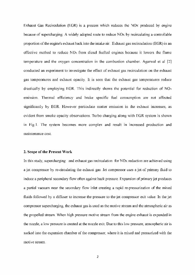
performance map of the given three cylinder diesel engine fitted with the EGR run jet compressor.
Figure.17 shows the comparison of percentage of EGR as a function of engine power obtained
from experiment and simulation for different boost pressures.
— 1 bar (simulation)
—A—1.2 bar (simulation)
—* —1.5 bar (simulation)
O 1 bar (experiment)
A 1.2 bar (experiment)
O 1.5 bar (experiment)
0 5 10 15Engine power kW
Fig.17. Comparison of simulated and experimental results of jet compressor supercharging.
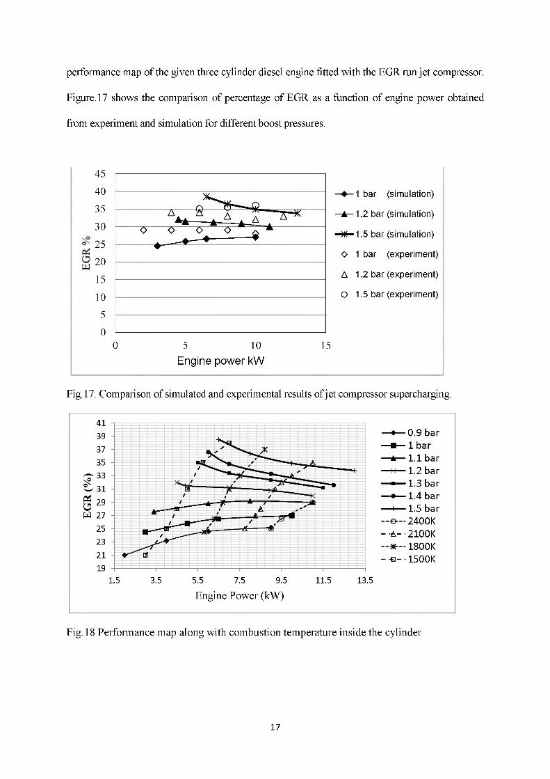
-♦— 0.9 bar « — 1 bar a — 1.1 bar----- 1.2 bar■■— 1.3 bar ■•— 1.4 bar h— 1.5 bar
2400K -■ A --2100K
1800K - - S - 1500K
1.5 3.5 5.5 7.5 9.5 11.5 13.5
Engine Power (kW)
Fig.18 Performance map along with combustion temperature inside the cylinder
17

Emissions of NOx from combustion are primarily in the form of NO. According to the
Zeldovich equation, the generation of NO is limited based on the availability of oxygen
present in air and the operating temperatures. At temperatures below 1300°C, the
concentration of NO generated is low compared to the higher concentration (about 200,000
ppm) generated above 2,300°C [14]. This shows that NOx emission from the engine is mostly
controlled by the engine operating temperature. Experiments were conducted by fixing boost
pressure with minimum combustion chamber temperature for different loads with and without
exhaust gas re-circulation and the results obtained are shown in Fig .19. The measured level of
NOx was found to decrease much compared to a naturally aspirated engine without EGR. The
reduction in the NOx level is due to the percentage of exhaust gas used in the jet compressor to
increase the engine power output.
Fig.19 Comparison of NOx level obtained from experiment with and without EGR.
7. Conclusions
In this study, a novel method of supercharging a diesel engine using the exhaust gas assisted jet
compressor was analyzed both numerically and experimentally. The specifications of the jet
compressor were determined using the constant momentum method. The engine operating
18

conditions were optimized using the available standard code for a given engine specifications.
From the optimized engine operating conditions, the input parameters for the jet compressor were
fixed. The performance of the jet compressor was then analyzed both using the commercially
available software Fluent as well as experimentally. The results were compared and found to be
closely matching. A performance map was drawn using which the optimum boost pressure and
maximum entrainment ratio could be obtained for a given percentage of exhaust gas recirculation
and power output. studies are also be made on thermodynamic aspect to improve the
performance of the jet compressor used for supercharging as well as to reduce the NOx emission.
Nomenclature
Tij symmetric stress tensor
puiuj Reynolds stress,
pCpuiT, turbulent heat flux
pO viscous dissipation A area(m )
Cp specific heat capacity at constant pressure(J kg"1K 1)
n efficiency
Y ratio of specific heat
c velocity(ms-1)
D diameter,(m)
F force(N)
L length (m)
Ld length of diffuser
m mass flow (kgms-1)
Ma Mach number
Mo momentum (kg m s-1)
P static pressure (Pa)
R individual gas constant (J kg ' 1K ' 1)
Rm ms/mg entrainment ratio
T static temperature (K)
TO total or stagnation temperature (K)
x axial distance from diffuser entry
19

P density (kgm-3)
0 diffuser half-angle(deg)
P constant
NOx oxides of Nitrogen
Subscripts
1 plane at entry to diffuser section
D diffuser
DE diffuser exit plane
g exhaust gas or primary flow condition
NE primary nozzle exit
o total or stagnation condition
s secondary flow stream
x co-ordinate along central axial of jet compressor
superscripts* Refers to critical condition of diffuser throat (Ma=1)
REFERENCES
1. Existing and Future Demands on the Turbo charging of Modern Large Two-stroke Diesel Engines Klaus Heim 1 Manager, R&D, Performance and Testing, Paper presented at the 8th Supercharging Conference 1-2 October 2002, Dresden.
2. Avinash Kumar Agrawal, Shrawan Kumar Singh, Shailendra Sinha , Mritunjay Kumar Shukla, “Effect of EGR on the exhaust gas temperature and exhaust opacity in compression ignition engines”, Sadhana Vol. 29, Part 3, pp. 275-284,2004.
3. Kroll, A. E., “The Design of Jet Pumps,” Chem. Eng. Prog., 1, 2 (1947).4. Keenan, J. H., and E. P. Neumann, “A Simple Air Ejector,” ASME J. Appl. Mech., 9
(1942).5. Holton, W. C., “Effect of Molecular Weight and Entrained Fluid on the Performance of
Steam-Jet Ejectors,” Trans. Am. Soc. Mech. Eng., 73 (1951).6. Ian W.Eames, “A new prescription for the design of supersonic jet-pumps: the constant
rate of momentum change method”, Int. journal of Applied Thermal Engineering, Vol. 22 p121-131, 2002.
7. S.B.Riffat, G.Gan and S.Smith, “Computational Fluid Dynamics applied to ejector heat pumps”, Applied Thermal Engineering, Vol. 16, No 4, pp291-297, 1996.
8. M.Ouzzane, Z.Aiddoum, “Model development and numerical procedure for detailed ejector analysis and design”, Applied Thermal Engineering, Vol. 23, 2003, page 23372351.
9. G.K.Alexes, E.D.Rogdakis, “A. verification study of steam -ejector refrigeration model”, Applied Thermal Engineering, Vol. 23, 2003, page 29-36.
20

10. Kanjanapon Chunnanond, Satha Apornratana, “An experimental investigation of a steam ejector refrigerator: the analysis of the pressure along the ejector” Applied Thermal Engineering, Vol. 24, 2004, page 311-322.
11. Nabel Beithou, Hikmet S. Ayber, “A mathematical model for steam driven jet pump”, international Journal of Multiphase flow, Vol. 26, 2000, page 1609-1619.
12. A.Arbel, A.Shklyar, D.Hershgal, M.Barak, M.Sokolov, “Ejector irreversibility characteristics”, Journal of Fluid Engineering Vol. 125, 2003, page 121-129.
13. V.Ganesan;”Computer simulation of Compression Ignition engine processes”; University Press (India) Ltd; New Delhi; 2000
14. Masahiro Misawa, Yuzo Aoyagi, Maysayuki Kobayashi, Odaka Matsuo, Goto Yuichi, High EGR diesel combustion and emission reduction study by single cylinder engine, Proceedings. JSAE Annual Congress, Vol. No 23-05; page.7-12(2005).
LIST OF PU BLIC A TIO NS O UT OF THIS RESEA RC H W O R K
I. PUBLISHED IN INTERNATIONAL / NATIONAL JOURNALS / CONFERENCES :
(a) International Journal :1. “IC Engine Supercharging and Exhaust Gas Recirculation using Jet Compressor”, A.
Kalaisselvane, N.Alagumurthy, K.Palaniradja, G.S.Gunasegarane. Internationaljournal of Thermal Science 2010 Volume 14, Issue 4, Pages: 1027-1037.
(b) International Conferences1. “Determination of Optimized Jet Compressor Parameters using DOE”,
A.Kalaisselvane, N.Alagumurthy, K.Pajaniradja, International conference on challenges and applications o f mathematics in science and technology, National Institute of Technology, Rourkela, Jan 2010.
2. “Optimization of jet compressor parameters using DOE” A.Kalaisselvane, N.Alagumurthy, International Conference on Advances in Industrial Engineering Applications, Anna University, Jan 2010.
(c) National Conferences1. “IC Engine Super Charging using Exhaust Gas Assisted Jet Compressor”,
A.Kalaisselvane, N.Alagumurthy, K.Pajaniradja, S.Sangeeth, National conference on low carbon technologies in automobile, Annamalai university, Feb 2009.
II. COMMUNICATED TO INTERNATIONAL JOURNALS :
1. “Performance improvement of jet compressor using forced draft system”, Kalaisselvane Adhimoulame, Alagumurthy Natarajan, Palaniradja Krishnaraj, Gunasegarane Selvaraj G. International journal of Aerospace (under review).
2. “Experimental investigation on diesel engine supercharging and exhaust gas recirculation (EGR) using exhaust gas assisted jet compressor” ,A. Kalaisselvane, G. S.Gunasegarane, N. Alagumurthy, K.Palaniradjaa, International journal of gas turbines and power (ASME) (under review).
21
Related Documents