i EXERCISE EQUIPMENT FOR ELECTRICAL ENERGY GENERATION

Exercise equipment for electrical energy generation- A Report
Aug 07, 2015
Welcome message from author
This document is posted to help you gain knowledge. Please leave a comment to let me know what you think about it! Share it to your friends and learn new things together.
Transcript
i
EXERCISE EQUIPMENT
FOR ELECTRICAL
ENERGY GENERATION
ii
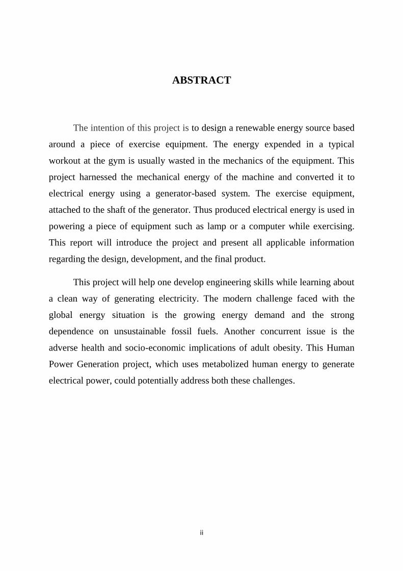
ABSTRACT
The intention of this project is to design a renewable energy source based
around a piece of exercise equipment. The energy expended in a typical
workout at the gym is usually wasted in the mechanics of the equipment. This
project harnessed the mechanical energy of the machine and converted it to
electrical energy using a generator-based system. The exercise equipment,
attached to the shaft of the generator. Thus produced electrical energy is used in
powering a piece of equipment such as lamp or a computer while exercising.
This report will introduce the project and present all applicable information
regarding the design, development, and the final product.
This project will help one develop engineering skills while learning about
a clean way of generating electricity. The modern challenge faced with the
global energy situation is the growing energy demand and the strong
dependence on unsustainable fossil fuels. Another concurrent issue is the
adverse health and socio-economic implications of adult obesity. This Human
Power Generation project, which uses metabolized human energy to generate
electrical power, could potentially address both these challenges.
iii
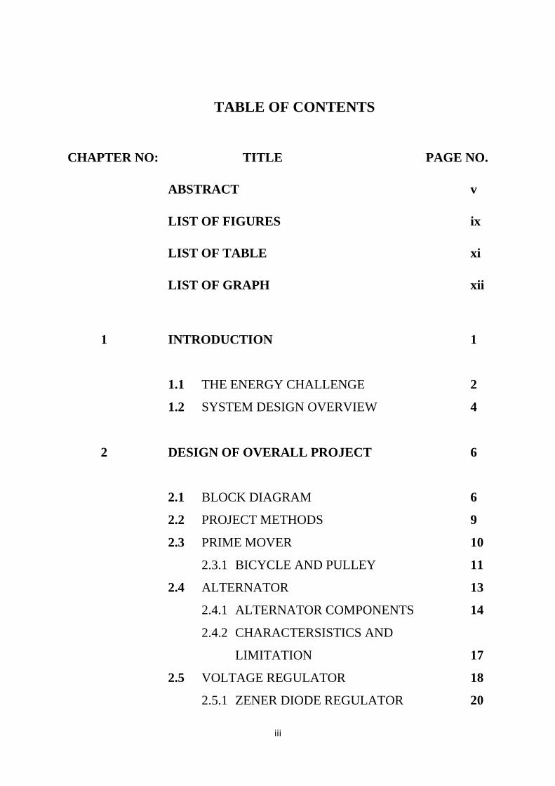
TABLE OF CONTENTS
CHAPTER NO: TITLE PAGE NO.
ABSTRACT v
LIST OF FIGURES ix
LIST OF TABLE xi
LIST OF GRAPH xii
1 INTRODUCTION 1
1.1 THE ENERGY CHALLENGE 2
1.2 SYSTEM DESIGN OVERVIEW 4
2 DESIGN OF OVERALL PROJECT 6
2.1 BLOCK DIAGRAM 6
2.2 PROJECT METHODS 9
2.3 PRIME MOVER 10
2.3.1 BICYCLE AND PULLEY 11
2.4 ALTERNATOR 13
2.4.1 ALTERNATOR COMPONENTS 14
2.4.2 CHARACTERSISTICS AND
LIMITATION 17
2.5 VOLTAGE REGULATOR 18
2.5.1 ZENER DIODE REGULATOR 20
iv
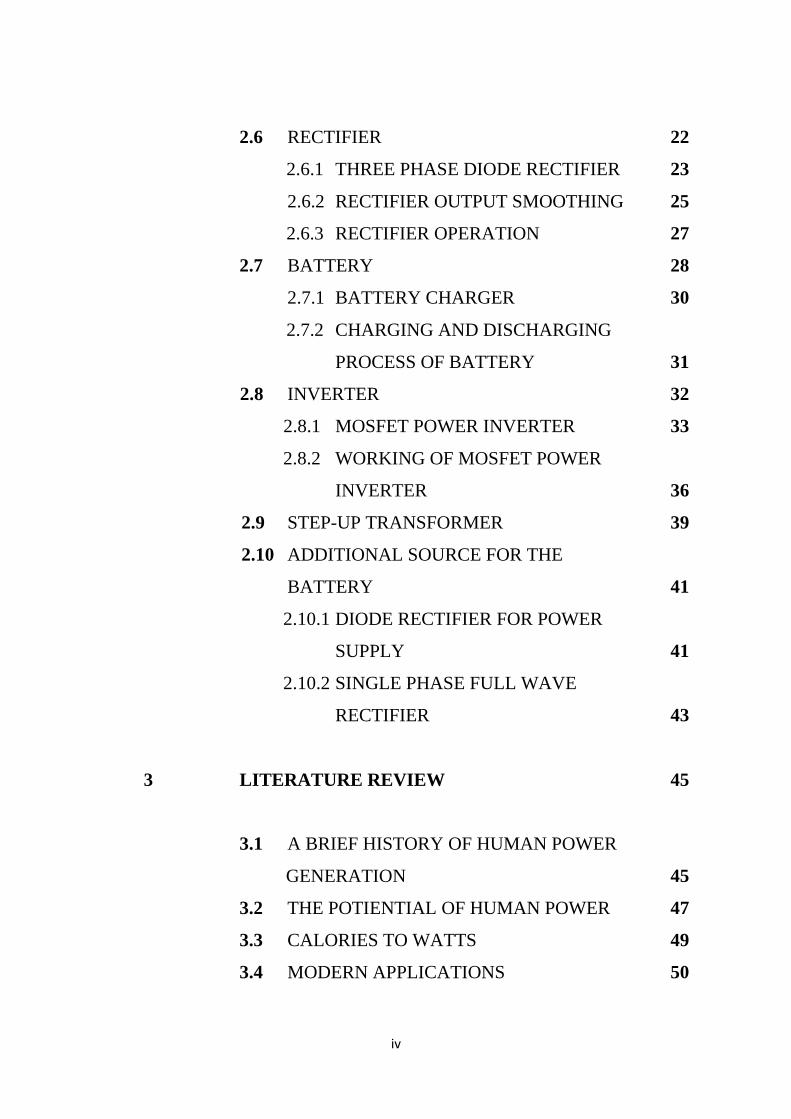
2.6 RECTIFIER 22
2.6.1 THREE PHASE DIODE RECTIFIER 23
2.6.2 RECTIFIER OUTPUT SMOOTHING 25
2.6.3 RECTIFIER OPERATION 27
2.7 BATTERY 28
2.7.1 BATTERY CHARGER 30
2.7.2 CHARGING AND DISCHARGING
PROCESS OF BATTERY 31
2.8 INVERTER 32
2.8.1 MOSFET POWER INVERTER 33
2.8.2 WORKING OF MOSFET POWER
INVERTER 36
2.9 STEP-UP TRANSFORMER 39
2.10 ADDITIONAL SOURCE FOR THE
BATTERY 41
2.10.1 DIODE RECTIFIER FOR POWER
SUPPLY 41
2.10.2 SINGLE PHASE FULL WAVE
RECTIFIER 43
3 LITERATURE REVIEW 45
3.1 A BRIEF HISTORY OF HUMAN POWER
GENERATION 45
3.2 THE POTIENTIAL OF HUMAN POWER 47
3.3 CALORIES TO WATTS 49
3.4 MODERN APPLICATIONS 50

v
4 IMPLEMENTATION AND RESUSLT 53
4.1 KEY REQUIREMENTS 53
4.2 ELECTRICAL SCHEMATIC DIAGRAM 54
4.3 ELEMENT SPECIFICATION 55
4.4 PROJECT ANALYSIS 55
4.5 RESULT 57
5 CONCLUSION 58
REFERENCES
vi
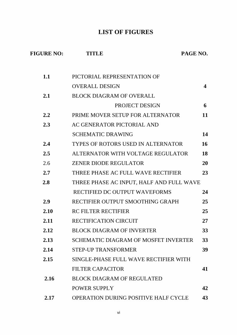
LIST OF FIGURES
FIGURE NO: TITLE PAGE NO.
1.1 PICTORIAL REPRESENTATION OF
OVERALL DESIGN 4
2.1 BLOCK DIAGRAM OF OVERALL
PROJECT DESIGN 6
2.2 PRIME MOVER SETUP FOR ALTERNATOR 11
2.3 AC GENERATOR PICTORIAL AND
SCHEMATIC DRAWING 14
2.4 TYPES OF ROTORS USED IN ALTERNATOR 16
2.5 ALTERNATOR WITH VOLTAGE REGULATOR 18
2.6 ZENER DIODE REGULATOR 20
2.7 THREE PHASE AC FULL WAVE RECTIFIER 23
2.8 THREE PHASE AC INPUT, HALF AND FULL WAVE
RECTIFIED DC OUTPUT WAVEFORMS 24
2.9 RECTIFIER OUTPUT SMOOTHING GRAPH 25
2.10 RC FILTER RECTIFIER 25
2.11 RECTIFICATION CIRCUIT 27
2.12 BLOCK DIAGRAM OF INVERTER 33
2.13 SCHEMATIC DIAGRAM OF MOSFET INVERTER 33
2.14 STEP-UP TRANSFORMER 39
2.15 SINGLE-PHASE FULL WAVE RECTIFIER WITH
FILTER CAPACITOR 41
2.16 BLOCK DIAGRAM OF REGULATED
POWER SUPPLY 42
2.17 OPERATION DURING POSITIVE HALF CYCLE 43

vii
2.18 OPERATION DURING NEGATIVE HALF CYCLE 43
2.19 FULL WAVE BRIDGE RECTIFIER WITH
CAPACITOR FILTER 44
4.1 SCHEMATIC DIAGRAM OF OVERALL DESIGN 54

viii
LIST OF TABLES
TABLE NO. TITLE PAGE NO.
3.1 ENERGY CONSUMPTION RATES OF COMMON
HUMAN ACTIVITIES 48
3.2 MAXIMUM POWER GENERATION CAPABILITY
FOR SOME HUMAN ACTIVITIES 48
ix
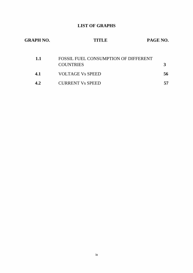
LIST OF GRAPHS
GRAPH NO. TITLE PAGE NO.
1.1 FOSSIL FUEL CONSUMPTION OF DIFFERENT
COUNTRIES 3
4.1 VOLTAGE Vs SPEED 56
4.2 CURRENT Vs SPEED 57
1
CHAPTER - 1
INTRODUCTION
The field of energy conservation is becoming an increasingly
notable subject of research among the scientific community today. The
intention of this project is to build a straight forward human powered
generator from a used bicycle and to use it to power light bulbs,
blenders, cell phones, laptops, and other small appliances. This project
will help one develop engineering skills while learning about a clean
way of generating electricity.
Over the past decade, scientists and engineers around the world
have been designing unprecedented energy-harvesting systems, drawing
power from a variety of sources. One of the most creative and unlimited
sources available is the kinetic energy produced from human exercise.
Although recent designs of energy-harvesting exercise equipment have
been introduced into the market, these systems are costly and do not
produce a noticeable output of power. These systems need to be
improved and designed for maximum power output, cost-efficiency, and
marketability. Engineered to be used for retrofitting an existing exercise
machine, this project includes an efficient yet controllable power storage
and distribution system.
The objective of this project is to design a renewable energy
source based around a piece of exercise equipment. Also, people who
are interested in minimizing environmental impacts and those who want
to preserve the environment will use this type of electrical energy
generation thereby reducing the emission of CO2 to the atmosphere.The
energy expended in a typical workout at the gym is usually wasted in the
mechanics of the equipment. This project harnessed the mechanical

2
energy of the machine and converted it to electrical energy using a
generator-based system. The exercise equipment will be attached to the
shaft of the generator. Thus produced electrical energy is used in
powering a piece of equipment such as lamp or a computer while
exercising.
1.1 THE ENERGY CHALLENGE
The world’s energy consumption is at an all time high with the
demand continuously increasing. This situation brings up several
challenges that need to be addressed.
Depletion due to finite availability of non-renewable energy
sources, e.g. fossil fuels
Environmental pollution, e.g. with coal use in power plants
Increasing population, especially in developing countries
which lack resources for clean energy.
Global warming with the related climate changes and
adverse implications
These challenges have been reason for much controversy in the
developed world; however, recent investigations have also shown a
much more basic challenge of availability in the less developed parts of
the world.
Data from the World Bank obtained as recently as 2014 estimated
that about 25.9% of the world’s population (greater than 1.81 billion
people) has no access to electricity. Larger numbers include those that
have very limited access to electricity. Further, most countries with the
lowest values for percent of population with electricity also have low
values of urban population percentage.

3
In terms of meeting the energy demand, data shows the high
dependence the world has overall on fossil fuels. Fossil fuels are known
to be non-renewable, having formed over millions of years of
decomposition of prehistoric biological forms such as plant matter and
the dinosaurs. The rate at which modern society is consuming these
resources is far quicker, however, risking the depletion of this resource.
Furthermore, the manner in which the resource is consumed is known to
produce pollutants (e.g. Carbon Monoxide (CO)) and green house gases
(e.g. Carbon Dioxide (CO2)) in our environment. Carbon Dioxide
emissions have been steadily growing through the combustion of fossil
fuels as needed in transportation, power generation and otherwise. One
of the main reasons why this is a critical problem is that the world
heavily depends on these fossil fuels currently to feed its energy
demands. Fig 1.1 illustrates the level and trends of fossil fuel use as
compared to total energy consumption over time in a few countries and
the world overall .
Fig 1.1 Fossil fuel consumption of different countries
4
Statistics shown here illustrate how the world on average depends
majorly on fossil fuels to supply energy. The trend in this parameter is
also of concern as the value has been stable around 80% for the past 15
years. The United States shows a slow decline but is still above the
world average. The trend of the most populous countries, China and
India, can also cause distress as the fossil fuel dependence is increasing
at a rapid rate over time. In the case of China, the value has superseded
that of the United States as of 2006. Therefore, it is established that with
the various energy challenges faced today, renewable energy sources
must be seriously investigated. Particularly, the feasibility of low-cost,
low maintenance and simple methods of providing energy to remote
areas should be studied. Such technology could not only help provide an
alternative to fossil fuel in developed countries, but also serve the
growing needs of developing countries in a responsible way.
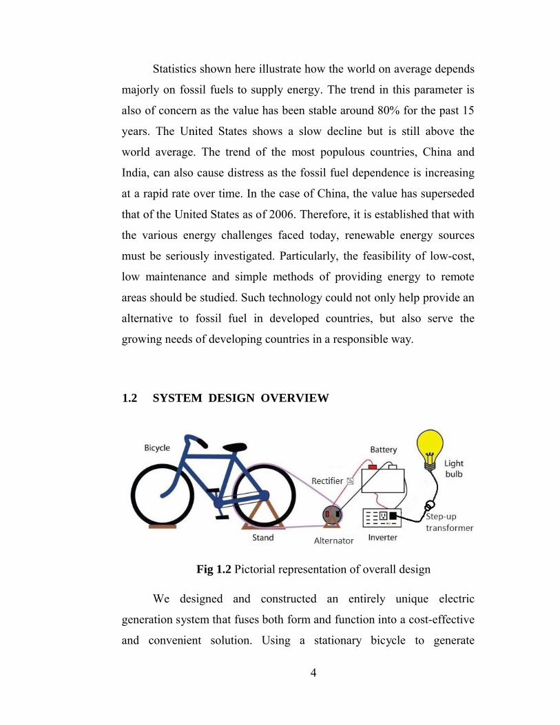
1.2 SYSTEM DESIGN OVERVIEW
Fig 1.2 Pictorial representation of overall design
We designed and constructed an entirely unique electric
generation system that fuses both form and function into a cost-effective
and convenient solution. Using a stationary bicycle to generate
5
electricity and charge a 12 volt battery, we obtain an output power of
approximately 60 watts – plenty of power for lights, an amplifier, an
iPod charger, and any unforeseen additional loads the student group may
attach later. The system provides about 5 hours of fully-loaded use, and
requires the equivalent for charging.
The system is comprised of several subsystems that will work
collectively to efficiently produce the desired 50 to 150 watts of power.
The first subsystem is the mechanical connection which is will
transfer the kinetic energy from pedaling to the generator.
The second subsystem is the electrical generator. This
subsystem transfers the rotational movement created when
bicycle is in use to the rotor of a generator which will in turn
output an AC voltage.
The third subsystem is the rectifier, which convert AC power
to DC. The fourth subsystem,thebattery and the battery
charger.
The Charge Controller adjusts the output to a single lead acid
battery to optimize the use of the generated energy. This
component will play a major factor in the efficiency of the
system.
The fifth subsystem is the inverter which convert the 12V DC
to 12 V AC.
A sixth subsystem is the step up transformer which step up the
12V AC to 230V AC supply.
The seventh and final subsystem is the additional power
supply for the battery when bicycle is not in use, which
consistsof single phase AC supply, rectifier and a step down
transformer.
6
CHAPTER- 2
LITERATURE REVIEW
2.1 A BRIEF HISTORY OF HUMAN POWER GENERATION
In 1817 Baron von Drais invented a walking machine that would
help him get around the royal gardens faster: two same-size in-line
wheels, the front one steerable, mounted in a frame which you straddled.
The device was propelled by pushing your feet against the ground, thus
rolling yourself and the device forward in a sort of gliding walk. The
machine became known as the Draisienne or hobby horse
The next appearance of a two-wheeled riding machine was in
1865, when pedals were applied directly to the front wheel. This
machine was known as the velocipede ("fast foot"), but was popularly
known as the bone shaker, since it was also made entirely of wood, then
later with metal tires, and the combination of these with the cobblestone
roads of the day made for an extremely uncomfortable ride.
In 1870 the first all metal machine appeared. (Previous to this
metallurgy was not advanced enough to provide metal which was strong
enough to make small, light parts out of.) The pedals were still attached
directly to the front wheel with no freewheeling mechanism. Solid
rubber tires and the long spokes of the large front wheel provided a
much smoother ride than its predecessor. The front wheels became
larger and larger as makers realized that the larger the wheel, the farther
you could travel with one rotation of the pedals.
Pedaling History has on display even the recent history of the
bicycle in America that we are more familiar with: the "English 3-speed"
7
of the '50s through the '70s, the 10-speed derailleur bikes which were
popular in the '70s (the derailleur had been invented before the turn of
the century and had been in more-or-less common use in Europe since),
and of course the mountain bike of right now. There are also many
oddball designs that never quite made it, including the Ingo.
1980-1991 A Los Angeles based company called Luz Co.
produced 95% of the world's solar-based electricity. They were forced to
shut their doors after investors withdrew from the project as the price of
non-renewable fossil fuels declined and the future of state and federal
incentives were not likely. The chairman of the board said it best: "The
failure of the world's largest solar electric company was not due to
technological or business judgment failures but rather to failures of
government regulatory bodies to recognize the economic and
environmental benefits of solar thermal generating plants”. Solar energy
history played a big part in the way society evolved and will continue to
do so. There is a renewed focus as more and more people see the
advantages of solar energy and as it becomes more and more affordable.
Human power has been instrumental in helping solve problems
since ancient times. For example, all tools have historically been human
powered. It is believed that the first human powered device to generate
rotary motion was the potter’s wheel, around 3,500 B.C.E. Later,
devices such as Archimedes� screw allowed efficient transfer of water
from one level to another. The Chinese, after 200 C.E., were found to
use hand cranks to aid in textile manufacturing, metallurgy and
agriculture. After the mid-15th century, the technique of incorporating
flywheels to produce smooth motion proliferated, allowing devices such
as the spinning wheel to gain popularity in Europe.
8
Cranks and pedal power became one of the most efficient means
of coupling human power to applications. In the 19th century, the
bicycle’s use of pedals allowed an efficient means of self-transportation.
In parallel with the invention of the electric dynamo in the 19th century,
it is speculated that pedal power was used to generate electric power as
early as then. However, with the burgeoning of the industrial revolution
in the 19th century and forward, human society found other ways of
powering their engineered applications.
Particularly, the availability of cheap and plentiful electricity,
powerful motors and disposable batteries can be attributed to the
decrease in popularity of using human strength. Also, the ethical
implications of having humans produce energy as punishment, as seen in
some prison mills, further diminished the popularity of human sourced
power. It would take until the latter half of the 20th century for science
to seriously reinvestigate this resource.
2.2 THE POTENTIAL OF HUMAN POWER
When the energy intake of humans is considered, a large potential
seems apparent. Considering the standard 2000kcal of daily
consumption (97W of power in, on average), humans take in about
8.368MJ or 2324Wh of energy every single day. This is approximately
the same amount of energy stored in the typical car battery (2400Wh) .
However, the expenditure of energy for common tasks is relatively high
as well as seen in Table 2.1 Also; Table 2.2 shows some values for
maximum power that can be captured as a result of human activity.

9
Table 2:1 Energy Consumption Rates of Common Human Activities
Activity Power Consumed (w)
Sleeping 81
Sitting 116
Swimming 582
Sprinting 1630
Table 2.2 Maximum Power Generation Capability for some Human
Activities
Activity Maximum Human Power (w)
Pushing button 0.64
Squeezing handle 12
Rotating crank 28
Riding bike >100
Hence, the available energy that can be captured over a short
period of time is in reality quite limited. To replace just one of the
largest capacity coal power plants in the United States (Arizona Public
Service Co, Palo Verde, AZ) would require approximately the
population of 2 New York City metro areas to be riding human power
generating bicycle :
10
The obvious impracticality of this figure shows why the scope
thus far in human power generation has been limited to lower power
applications such as consumer electronics
Producing 1800 watts for a few seconds should be within the
range of the best power lifters and perhaps for up to a minute.
Remember 1 watt means applying a force of 1 newton through a
distance of 1 meter in 1 second. So if you lifted 1 kg, that's 9.8 newtons
of force, about 10newtons, for 1 meter in 1 second, that would be 10
watts. So lifting 180 kg, 1 meter high in 1 second would be 1800 watts.
The best power lifters can do squats of several times their body weight
for 1 rep. Let's say the power lifter weighed 100 kg, about 220 lbs. He
might be able to do 3 times his weight for a single rep. That would be
300 kg. But remember he's actually raising his own weight as well. So
he's actually lifting 4 times his weight, 400 kg for this one rep. For a
male of average height, he might be raising this over a distance of 1
meter. So doing 1800 watts of power for one minute would be like
giving this power lifter a weight of only 60 kg (for a total weight of 180
kg) and doing squats with this light weight for the high number of reps
of 1 per second over one minute. This would be possible for a weight so
much lighter than their usual 1 rep maximum weight.
2.3 CALORIES TO WATTS
First keep in mind that Watts and Calories are two different units
of measurement that can't be directly converted back and forth. However
if you use Watt-Hours instead of just "Watts" you then have a way to
convert to calories. Here are the steps: Convert Watt-Hours to Watt-
Seconds (Joules), then convert Joules to Calories, then adjust Calories
with human body efficiency factor. So for this example let's assume that
11
you provide pedal power to a 100 Watt television for one hour. Since
one Joule is equal to one Watts X Seconds you perform dimensional
analysis and get:
100Watt-hours X (3600 seconds / 1 Hour) = 360,000 J
Now use the conversion factor:
1 cal = 4.184 J to convert Joules to Calories
360,000 J / 4.184 = 86,042 Calories
When you look at the label of Oreo cookies or other food items at
the store, the term "Calories" is really (kilo-Calories). So you divide by
1000 to get 86 Calories. Assuming that your body is about 25% efficient
when cycling you divide by 0.25: Calories burned running a 100 Watt
Television for 1 hour = 86 / 0.25 = 344 which is about equivalent to one
piece of pizza.
2.4 MODERN APPLICATIONS
Today, human power has made sort of a comeback with many
applications where it can be of use and the reason to investigate
alternative energy. A novel feeling of empowerment is recognized when
people are able to do things for which they had to rely on machines
previously. So much so, that the idea of powering solely from human
energy exists as a technical challenge. For example, the American
Society of Mechanical Engineers (ASME) holds the Human Powered
Vehicle Challenge (HPVC) competition annually for encouraging higher
education students to construct and compete with single-driver
prototypes power by the driver alone. Further, the Royal Aeronautical
Society has various challenges for the Kramer’s prizes in human
12
powered flight. The end goal of this initiative is to qualify such an
endeavor to be a competitive sport, possibly a part of the Olympics.
Human power has also been found to be uniquely good at
providing energy generation in isolated situations. For example, the
development of hand-operated axial flux generators which can be useful
for dismounted soldiers, search and rescue operation in case of natural
disasters, relief workers in remote regions and field scientists. The study
demonstrates how 60W can be maintained from the generator for
different applications while maintaining a lightweight design for
portability. Further, provides a good example of applying human power
in remote areas of developing countries. In 1991, at the time of the
study, many rural parts of India lacked any access to electricity. Further,
fossil fuel or solar/wind energy generation required skill in operation
and maintenance along with monetary resources that were unavailable.
Human energy was determined to be simple, dependable, required
low capital, and reliable for the application of desalinating local water.
The successful implementation of a pedal powered system in the rural
area produced a sustainable 100W to power the desalination system.
This let clean water be available to the people locally, avoiding the need
to walk 2km daily as done previously. This localized generation of
electricity has also made human power an excellent method for micro-
power generation.
Theoretical analyses have been done to show that brisk walking
motion can produce up to 5-8W, adequate for basic wearable computing.
Recent research shows the performance of three methods to perform this
extraction. Summary of current progress in piezoelectric generator
technology shows power generation capabilities of up to 8400μW.

13
Further, small-scale electromagnetic generators are a little harder to
manufacture but can produce power in the order of mW. The
development of a electrostatic generator which uses microball
movement induced by low frequency human motion to generate at least
40μW. Such output power may seem relatively negligible but it has
potential in partially or completely removing the need for batteries,
making portable designs lighter, smaller and longer lasting. This is
especially promising for applications such as implantable and wearable
electronics, ambient intelligence, condition monitoring devices, and
wireless sensor networks.
Hence, it is seen that human power generation has multiple
applications in modern society. It can be useful when users are isolated
as possible with natural disaster, military deployment or being in a
remote area. It also provides for an intuitive, easy to implement and
relatively low cost design which is particularly useful in rural areas of
developing nations where skill in operating equipment and investment
capital is limited. Acquisition of energy via no deliberate human effort is
also possible which could be useful for various novel portable
electronics applications. Furthermore, it can allow for power generation
to be done socially, removing the feeling of deliberate effort while
increasing the power output significantly. The thought of using human
energy as an alternative and renewable energy source is gaining
popularity to the level that businesses have formed around converting
exercise equipment such as stationary bikes and ellipticals to electricity
generators.
14
CHAPTER -3
DESIGN OF OVERALL PROJECT
3.1 BLOCK DIAGRAM
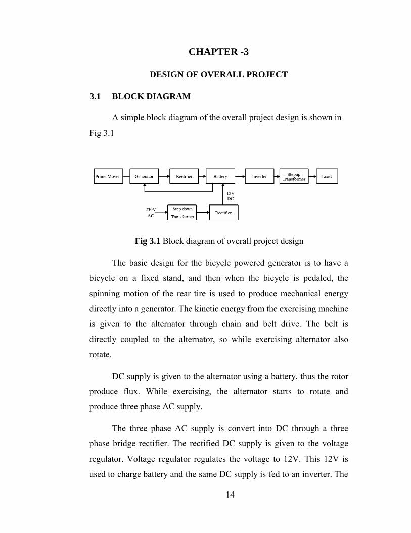
A simple block diagram of the overall project design is shown in
Fig 3.1
Fig 3.1 Block diagram of overall project design
The basic design for the bicycle powered generator is to have a
bicycle on a fixed stand, and then when the bicycle is pedaled, the
spinning motion of the rear tire is used to produce mechanical energy
directly into a generator. The kinetic energy from the exercising machine
is given to the alternator through chain and belt drive. The belt is
directly coupled to the alternator, so while exercising alternator also
rotate.
DC supply is given to the alternator using a battery, thus the rotor
produce flux. While exercising, the alternator starts to rotate and
produce three phase AC supply.
The three phase AC supply is convert into DC through a three
phase bridge rectifier. The rectified DC supply is given to the voltage
regulator. Voltage regulator regulates the voltage to 12V. This 12V is
used to charge battery and the same DC supply is fed to an inverter. The
15
inverter is made is made with MOSFET and driver circuit. The output of
the inverter is 12V AC supply with a frequency of 50 Hz. This AC
supply is step up to 230 V by using step up transformer.
When the exercise machine is not used, the main supply is used to
charge the battery. For that charging step down transformer and bridge
rectifier is used. The output of the transformer is 12V AC. This 12 V AC
is converted to DC by using diode bridge rectifier. The output from the
diode rectifier is directly connected to the battery. So the battery also
charges while the exercise machine is not in use. In our project, we are
using a 40 W incandescent lamp as load.
This project has various different design paths to complete our
product while meeting the majority objectives. This means we will have
to implement and compare our different designs to insure the best
product based on our set of objectives. These paths have changed as we
progressed through our project, and there were a few foreseen methods
that we expand upon in the design section.
The basic design for the bicycle powered generator is to have a
bicycle on a fixed stand, and then when the bicycle is pedaled, the
spinning motion of the rear tire is used to produce mechanical energy
directly into a generator. Alternator is the device by which mechanical
energy is converted into electrical energy. It is D.C. generator for
generating D.C. voltage at output. Rectifier circuit It is a device which
converts A.C. voltage into D.C. voltage. Some A.C. harmonics produced
by D.C. generator with pulsating modulation of waves which is not in
regular modulation, so for getting regular modulation of waves, rectifier
circuit is used Filter circuit at the output of rectifier.
16
DC voltage is not in pure form some A.C. components are in
there so for purification of it, Shunt capacitor filter circuit is used. Filter
is a circuit which minimizes of removed the undesirable A.C.
component of the rectifier output & allows only the D.C. component to
reach at output. Charging circuit It is the circuit which is used for
charging the discharged battery. Voltage limiting circuit:- It is also
called as voltage regulator circuit. Here, for voltage regulation of output
voltage, zener diode is used.
Voltage regulator is the circuit which eliminates or reduced
variations in the D.C. output voltage or rectifier and filter circuit are
called Voltage Regulator. Battery It is the source of D.C. voltage. It is
the device where we want to store the D.C. voltage or it gives the D.C.
source whenever we want. Inverter we are using electronic inverter. The
function of electronic inverter is to convert D.C. to A.C. In our project
we are generating 12 volt D.C. supply to convert 12 volt D.C. to 230
volt A.C. with the help of electronic inverter unit.
The function of inverter is to take the 12 volt D.C. and switching
the 12 volt D.C. and give the step-up transformer convert 12 volt
switching supply to 230 volt A.C. supply. It is most common part of
inverter. If an AC voltage is produced, a full bridge rectifier will be
necessary to produce the DC voltage. This DC voltage can then be used
immediately or stored via a battery array.
The first decision is selecting a bill of materials for each design
path. This will help determine the ultimate product affordability. We
must decide whether to use an alternator or dynamo to convert the
bicycles mechanical energy to AC or DC, respectively. While an
alternator is easier to find and purchase with many functioning units
17
available in scrap yards, they also tend to be less efficient in the output
of DC power compared to a dynamo.
Another design factor that must be implemented and compared is
the coupling of the bicycle wheel to either the alternator or dynamo
rotor. One option is to use two contacting wheels to connect the two
components. This option is a bit simpler to implement and take very
little upkeep to maintain; however, the efficiency of the contact is
relatively low due to slippage losses and frictional losses. A more
efficient yet expensive design would be to have the wheel and the
alternator/dynamo be connected via a rotary belt, similar to a car belt
system. There are bound to be various other obstacles and design
methods to be implemented as the project progresses, and will be
observed and recorded as they occur.
3.2 PROJECT METHODS
This project has various different design paths to complete our
product while meeting the majority objectives. This means we will have
to implement and compare our different designs to insure the best
product based on our set of objectives. These paths have changed as we
progressed through our project, and there were a few foreseen methods
that we expand upon in the design section.
The basic design for the bicycle powered generator is to have a
bicycle on a fixed stand, and then when the bicycle is pedaled, the
spinning motion of the rear tire is used to produce mechanical energy
directly into a DC voltage. If an AC voltage is produced, a full bridge
rectifier will be necessary to produce the DC voltage. This DC voltage
can then be used immediately or stored via a battery array. If a constant
DC voltage is required by the using a voltage regulator may be
18
necessary to change the varying DC voltages produced from the varying
bicycle speed to a constant DC voltage for certain utilities or battery
array.
The first decision is selecting a bill of materials for each design
path. This will help determine the ultimate product affordability. We
must decide whether to use an alternator or dynamo to convert the
bicycles mechanical energy to AC or DC, respectively.
While an alternator is easier to find and purchase with many
functioning units available in scrap yards, they also tend to be less
efficient in the output of DC power compared to a dynamo. Another
design factor that must be implemented and compared is the coupling of
the bicycle wheel to either the alternator or dynamo rotor. One option is
to use two contacting wheels to connect the two components.
This option is a bit simpler to implement and take very little
upkeep to maintain; however, the efficiency of the contact is relatively
low due to slippage losses and frictional losses. A more efficient yet 15
expensive design would be to have the wheel and the alternator/dynamo
be connected via a rotary belt, similar to a car belt system. There are
bound to be various other obstacles and design methods to be
implemented as the project progresses, and will be observed and
recorded as they occur.
3.3 PRIME MOVER
All generators, large and small, ac and dc, require a source
of mechanical power to turn their rotors. This source of mechanical
energy is called a prime mover. Prime movers are divided into two
classes for generators-high-speed and low-speed. Steam and gas turbines
are high-speed prime movers, while internal-combustion engines, water,
19
and electric motors are considered low-speed prime movers. The type of
prime mover plays an important part in the design of alternators since
the speed at which the rotor is turned determines certain
characteristics of alternator construction and operation.
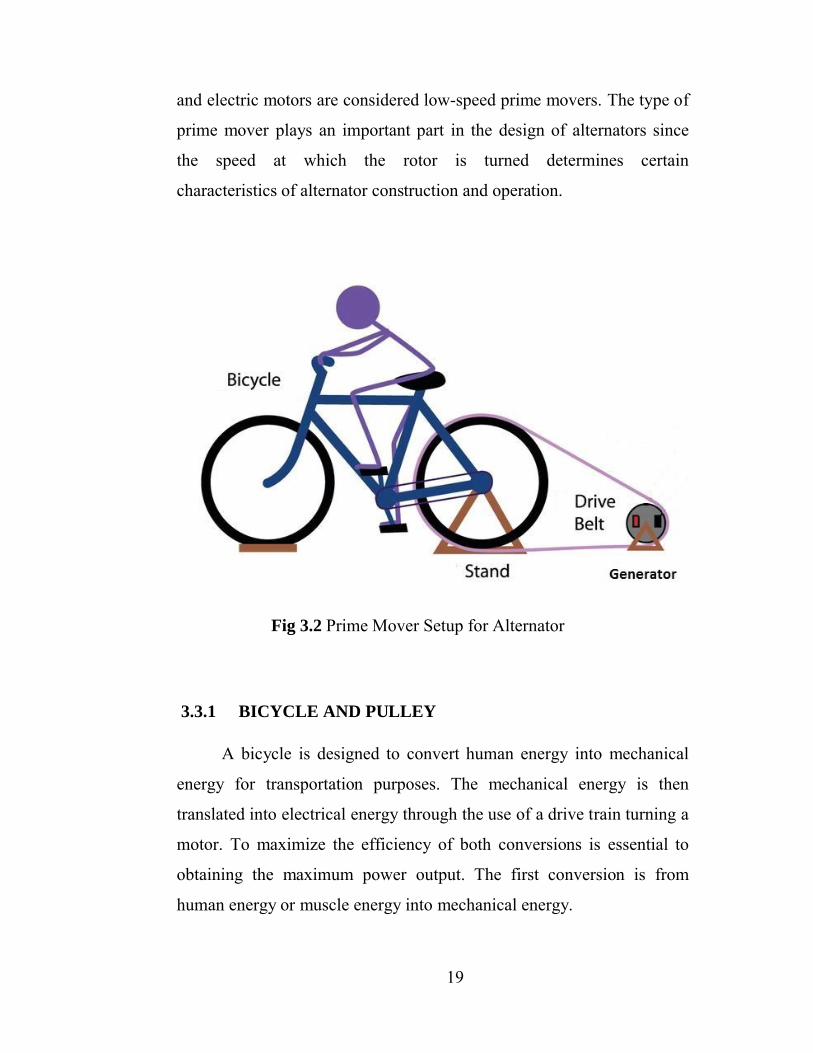
Fig 3.2 Prime Mover Setup for Alternator
3.3.1 BICYCLE AND PULLEY
A bicycle is designed to convert human energy into mechanical
energy for transportation purposes. The mechanical energy is then
translated into electrical energy through the use of a drive train turning a
motor. To maximize the efficiency of both conversions is essential to
obtaining the maximum power output. The first conversion is from
human energy or muscle energy into mechanical energy.
20
The bicycle is an efficient and robust method to convert between
the two types of energy. It is an efficient design that provides seating for
the user as well as pedals and drive train that are easily activated. There
are few moving parts and the simplicity of design is proven.
Pedaling is the most efficient way of utilizing power from human
muscles. Pedal power enables a person to drive devices at the same or
higher rate as that achieved by hand cranking, but with far less effort and
fatigue. The human musculature is concentrated in our legs and the
bicycle set-up allows for harnessing the maximum output.
The stationary power generation on bicycles has been skipped
over in past research but with the rising cost of other power generation,
reliance on human power generation will become more important;
furthermore, the bicycle is a universal symbol of transportation in all
types of countries especially developing ones. We can find bicycles
everywhere and the robustness of the simple mechanical system makes
the learning curve essentially zero.
The rotational nature of the bicycle drive train or more
specifically the pedals is a steady style of movement. The constant
driving of the pedals become more constant when reaching the drive
train since there is rotational inertia to smooth out any subtle changes in
the speed. The rear wheel therefore becomes an ideal prime mover for
electrical generation; we would need to connect an alternator and rear
wheel though either direct contact or a belt system. The user is able to
start softly and increase the resistance as momentum is gained.
When the bicycle stabilizes and gains more speed, then the user
down-shift thereby increasing perceived resistance and outputs more
power. The same approach can be used by the user of our stationary
21
power generation set-up. This factor comes into play further when
developing the motor for the bicycle design.
A pulley is a wheel on an axle that is designed to support
movement of a cable or belt along its circumference. Pulleys are used in
a variety of ways to lift loads, apply forces, and to transmit power.
Round belts Round belts are a circular cross section belt designed to run
in a pulley with a 60 degree V-groove. Round grooves are only suitable
for idler pulleys that guide the belt, or when (soft) O-ring type belts are
used.
3.4 ALTERNATOR
Here the alternator is used to charge the battery and to power the
electrical system when the bicycle is pedaling. The last practical option
to implement for the bicycle system was to use a standard car alternator.
This seems to be the most reasonable motor for the design, as car
alternators are widely available worldwide for relatively low costs when
purchased as a used part.
An alternator is an electrical generator that converts mechanical
energy to electrical energy in the form of alternating current. For reasons
of cost and simplicity, most alternators use a rotating magnetic field with
a stationary armature. Occasionally, a linear alternator or a rotating
armature with a stationary magnetic field is used. In principle,
any AC electrical generator can be called an alternator, but usually the
term refers to small rotating machines driven by automotive and other
internal combustion engines. An alternator that uses a permanent
magnet for its magnetic field is called a magneto. The alternator consists
of two main parts, rotor and the stator.
22
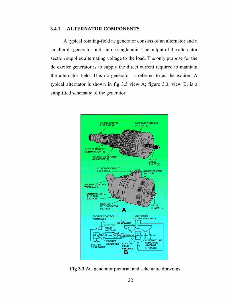
3.4.1 ALTERNATOR COMPONENTS
A typical rotating-field ac generator consists of an alternator and a
smaller dc generator built into a single unit. The output of the alternator
section supplies alternating voltage to the load. The only purpose for the
dc exciter generator is to supply the direct current required to maintain
the alternator field. This dc generator is referred to as the exciter. A
typical alternator is shown in fig 3.3 view A; figure 3.3, view B, is a
simplified schematic of the generator.
Fig 3.3 AC generator pictorial and schematic drawings.
23
The exciter is a dc, shunt-wound, self-excited generator. The
exciter shunt field (2) creates an area of intense magnetic flux between
its poles. When the exciter armature (3) is rotated in the exciter-field
flux, voltage is induced in the exciter armature windings. The output
from the exciter commutator (4) is connected through brushes and slip
rings (5) to the alternator field. Since this is direct current already
converted by the exciter commutator, the current always flows in one
direction through the alternator field (6). Thus, a fixed-polarity magnetic
field is maintained at all times in the alternator field windings. When the
alternator field is rotated, its magnetic flux is passed through and across
the alternator armature windings (7).
The armature is wound for a three-phase output, which will be
covered later in this chapter. Remember, a voltage is induced in a
conductor if it is stationary and a magnetic field is passed across the
conductor, the same as if the field is stationary and the conductor is
moved. The alternating voltage in the ac generator armature windings is
connected through fixed terminals to the ac load.
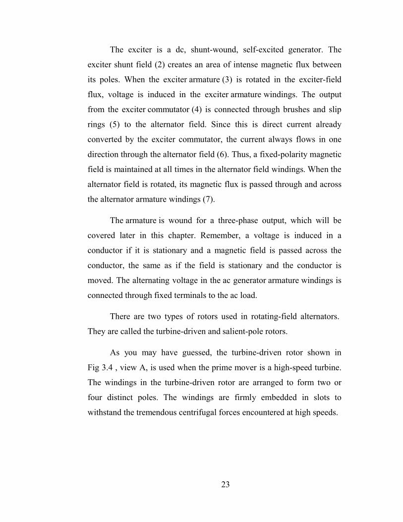
There are two types of rotors used in rotating-field alternators.
They are called the turbine-driven and salient-pole rotors.
As you may have guessed, the turbine-driven rotor shown in
Fig 3.4 , view A, is used when the prime mover is a high-speed turbine.
The windings in the turbine-driven rotor are arranged to form two or
four distinct poles. The windings are firmly embedded in slots to
withstand the tremendous centrifugal forces encountered at high speeds.
24
Fig 3.4 Types of rotors used in alternators
The salient-pole rotor shown in figure 3.4, view B, is used in low-
speed alternators. The salient-pole rotor often consists of several
separately wound pole pieces, bolted to the frame of the rotor.
If you could compare the physical size of the two types of rotors
with the same electrical characteristics, you would see that the salient-
pole rotor would have a greater diameter. At the same number of
revolutions per minute, it has a greater centrifugal force than does the
turbine-driven rotor.
To reduce this force to a safe level so that the windings will not be
thrown out of the machine, the salient pole is used only in low-speed
designs.
25
3.4.2 CHARACTERISTICS AND LIMITATIONS
Alternators are rated according to the voltage they are designed to
produce and the maximum current they are capable of providing. The
maximum current that can be supplied by an alternator depends upon the
maximum heating loss that can be sustained in the armature. This
heating loss (which is an I2R power loss) acts to heat the conductors, and
if excessive, destroys the insulation. Thus, alternators are rated in terms
of this current and in terms of the voltage output - the alternator rating in
small units is in volt-amperes; in large units it is kilovolt-amperes.
Once the finger poles and shaft are removed, the coil of the rotor
can be rewound with thinner wire more times. From Farraday’s
equation, , we find that as N (number of turns)
increases, ε (electromagnetic force) increases proportionally. With the
higher EMF, we produce more power from less rotor rotations. In other
words, with a rewrapped rotor we can produce more power with lower
RPMs. While more current will be produced at lower RPMs this is
because the EMF is much bigger, which in turn will give the users
another problem, the EMF-produced resistance. An EMF in a motor is
not a problem until you are the one actually supplying the rotation of the
shaft. A higher EMF means the user will experience a higher resistance
in their pedaling. This ―inductance hump� of starting to pedal will tire
the user greatly if a full field is being produced by the stator. To resolve
this issue a few different ideas were implemented to reduce the pedaling
resistance in the alternator.
26
3.5 VOLTAGE REGULATOR
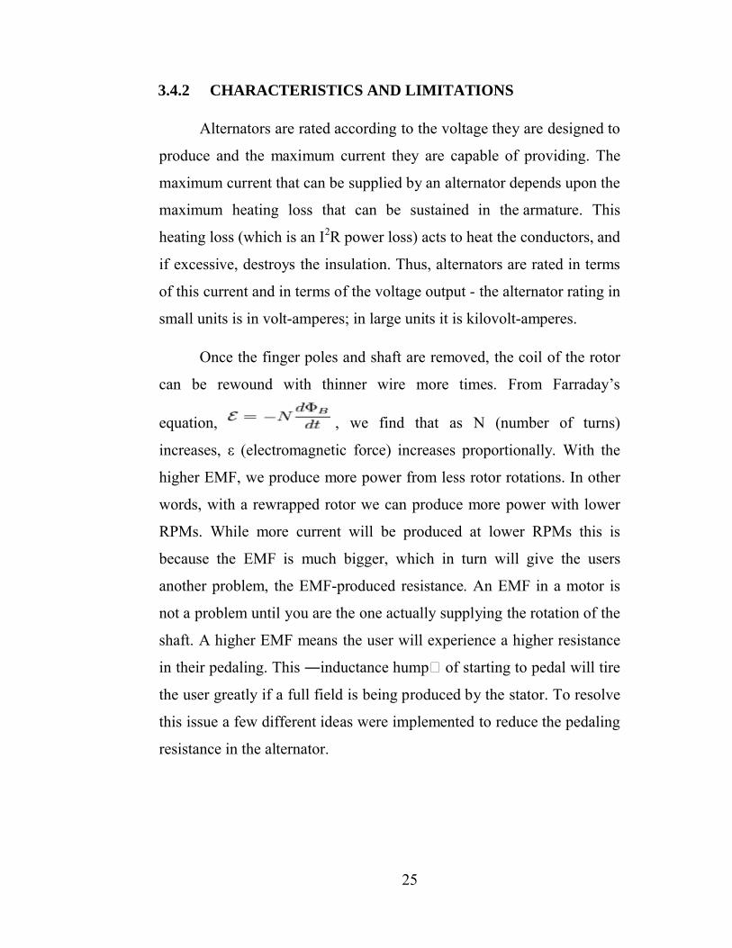
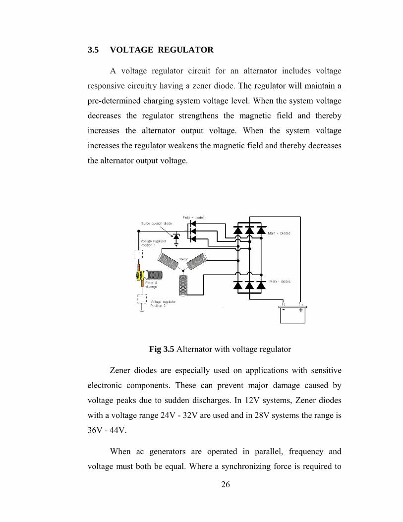
A voltage regulator circuit for an alternator includes voltage
responsive circuitry having a zener diode. The regulator will maintain a
pre-determined charging system voltage level. When the system voltage
decreases the regulator strengthens the magnetic field and thereby
increases the alternator output voltage. When the system voltage
increases the regulator weakens the magnetic field and thereby decreases
the alternator output voltage.
Fig 3.5 Alternator with voltage regulator
Zener diodes are especially used on applications with sensitive
electronic components. These can prevent major damage caused by
voltage peaks due to sudden discharges. In 12V systems, Zener diodes
with a voltage range 24V - 32V are used and in 28V systems the range is
36V - 44V.
When ac generators are operated in parallel, frequency and
voltage must both be equal. Where a synchronizing force is required to
27
equalize only the voltage between dc generators, synchronizing forces
are required to equalize both voltage and speed (frequency) between ac
generators. On a comparative basis, the synchronizing forces for ac
generators are much greater than for dc generators. When ac generators
are of sufficient size and are operating at unequal frequencies and
terminal voltages, serious damage may result if they are suddenly
connected to each other through a common bus. To avoid this, the
generators must be synchronized as closely as possible before
connecting them together.
The output voltage of an alternator is best controlled by regulating
the voltage output of the dc exciter, which supplies current to the
alternator rotor field. This is accomplished as shown in Fig 2.5, by a
zener diode regulator of a 28 volt system connected in the field circuit of
the exciter. The zener diode regulator controls the exciter field current
and thus regulates the exciter output voltage applied to the alternator
field.
The only difference between the dc system and the ac system is
that the voltage coil receives its voltage from the alternator line instead
of the dc generator. In this arrangement, a three phase, step down
transformer connected to the alternator voltage supplies power to a three
phase, full wave rectifier. The 28 volt, dc output of the rectifier is then
applied to the zener diode voltage regulator. Changes in alternator
voltage are transferred through the transformer rectifier unit to the zener
diode. This controls the exciter field current and the exciter output
voltage. The exciter voltage antihunting or damping transformer is
similar to those in dc systems and performs the same function.
28
The DC output voltage from the half or full-wave rectifiers
contains ripple superimposed onto the DC voltage and that as the load
value changes so to does the average output voltage. By connecting a
simple zener stabilizer circuit as shown below across the output of the
rectifier, a more stable output voltage can be produced.
3.5.1 ZENER DIODE REGULATOR
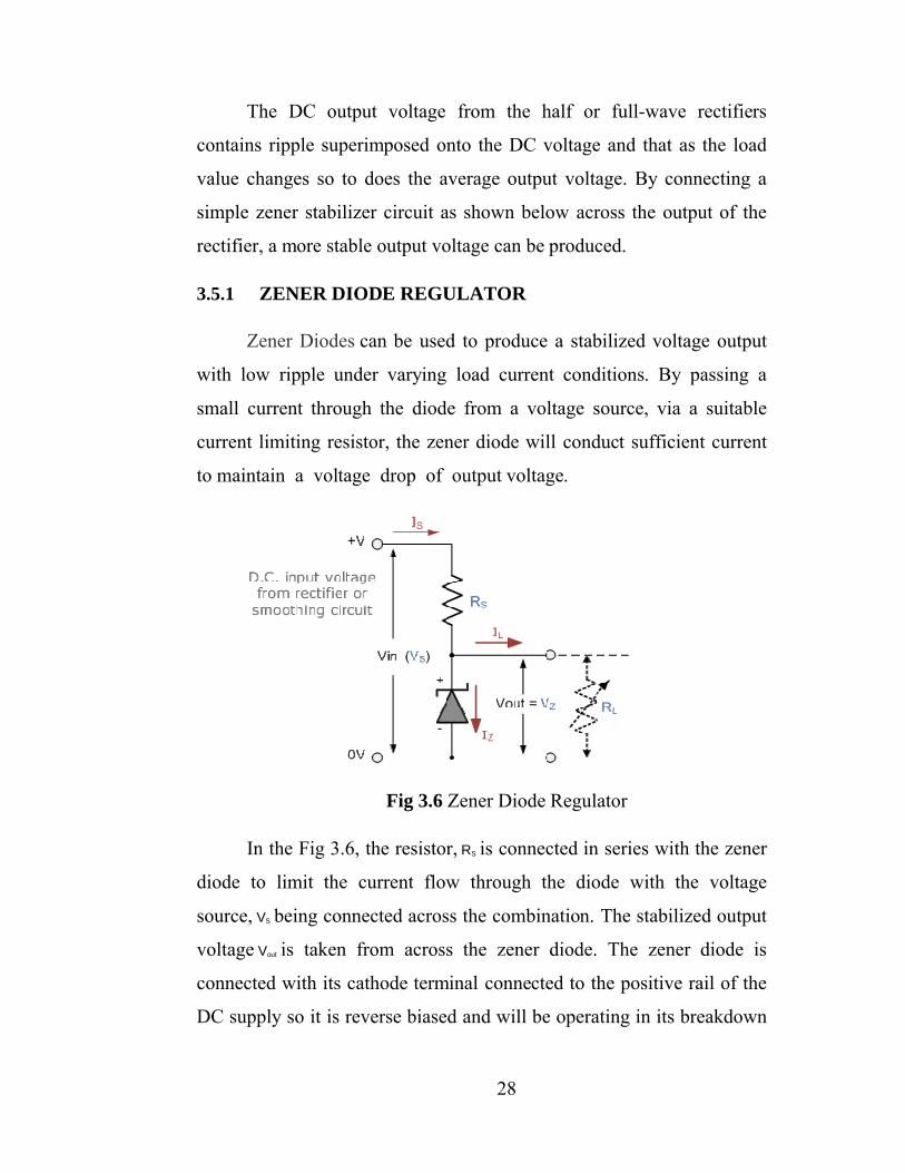
Zener Diodes can be used to produce a stabilized voltage output
with low ripple under varying load current conditions. By passing a
small current through the diode from a voltage source, via a suitable
current limiting resistor, the zener diode will conduct sufficient current
to maintain a voltage drop of output voltage.
Fig 3.6 Zener Diode Regulator
In the Fig 3.6, the resistor, RS is connected in series with the zener
diode to limit the current flow through the diode with the voltage
source, VS being connected across the combination. The stabilized output
voltage Vout is taken from across the zener diode. The zener diode is
connected with its cathode terminal connected to the positive rail of the
DC supply so it is reverse biased and will be operating in its breakdown
29
condition. Resistor RS is selected so to limit the maximum current
flowing in the circuit.
With no load connected to the circuit, the load current will be
zero, ( IL = 0 ), and all the circuit current passes through the zener diode
which in turn dissipates its maximum power. Also a small value of the
series resistor RS will result in a greater diode current when the load
resistance RL is connected and large as this will increase the power
dissipation requirement of the diode so care must be taken when
selecting the appropriate value of series resistance so that the zener’s
maximum power rating is not exceeded under this no-load or high-
impedance condition.
The load is connected in parallel with the zener diode, so the
voltage across RL is always the same as the zener voltage, ( VR = VZ ). There
is a minimum zener current for which the stabilization of the voltage is
effective and the zener current must stay above this value operating
under load within its breakdown region at all times. The upper limit of
current is of course dependent upon the power rating of the device. The
supply voltage VS must be greater than VZ.
One small problem with zener diode stabilizer circuits is that the
diode can sometimes generate electrical noise on top of the DC supply
as it tries to stabilize the voltage. Normally this is not a problem for most
applications but the addition of a large value decoupling capacitor across
the zener’s output may be required to give additional smoothing.
Then to summarize a little. A zener diode is always operated in its
reverse biased condition. A voltage regulator circuit can be designed
using a zener diode to maintain a constant DC output voltage across the
load in spite of variations in the input voltage or changes in the load
30
current. The zener voltage regulator consists of a current limiting
resistor RS connected in series with the input voltage VS with the zener
diode connected in parallel with the load RL in this reverse biased
condition. The stabilized output voltage is always selected to be the
same as the breakdown voltage VZ of the diode.
3.6 RECTIFIER
Rectifier is an electrical device that converts alternating
current (AC), which periodically reverses direction, to direct
current (DC), which flows in only one direction. The process is known
as rectification. Physically, rectifiers take a number of forms,
including vacuum tube diodes, mercury-arc valves, copper and selenium
oxide rectifiers, semiconductor diodes, silicon-controlled rectifiers and
other silicon-based semiconductor switches. Historically, even
synchronous electromechanical switches and motors have been used.
Early radio receivers, called crystal radios, used a "cat's whisker" of fine
wire pressing on a crystal of galena (lead sulfide) to serve as a point-
contact rectifier or "crystal detector".
Rectifiers have many uses, but are often found serving as
components of DC power supplies and high-voltage direct current power
transmission systems. Rectification may serve in roles other than to
generate direct current for use as a source of power.
Because of the alternating nature of the input AC sine wave, the
process of rectification alone produces a DC current that, though
unidirectional, consists of pulses of current. Many applications of
rectifiers, such as power supplies for radio, television and computer
equipment, require a steady constant DC current (as would be produced
by a battery). In these applications the output of the rectifier is smoothed
by an electronic filter
Rectifier circuits may be single
the most common number of phas
domestic equipment are single
very important for industrial applications and for the transmission of
energy as DC (HVDC
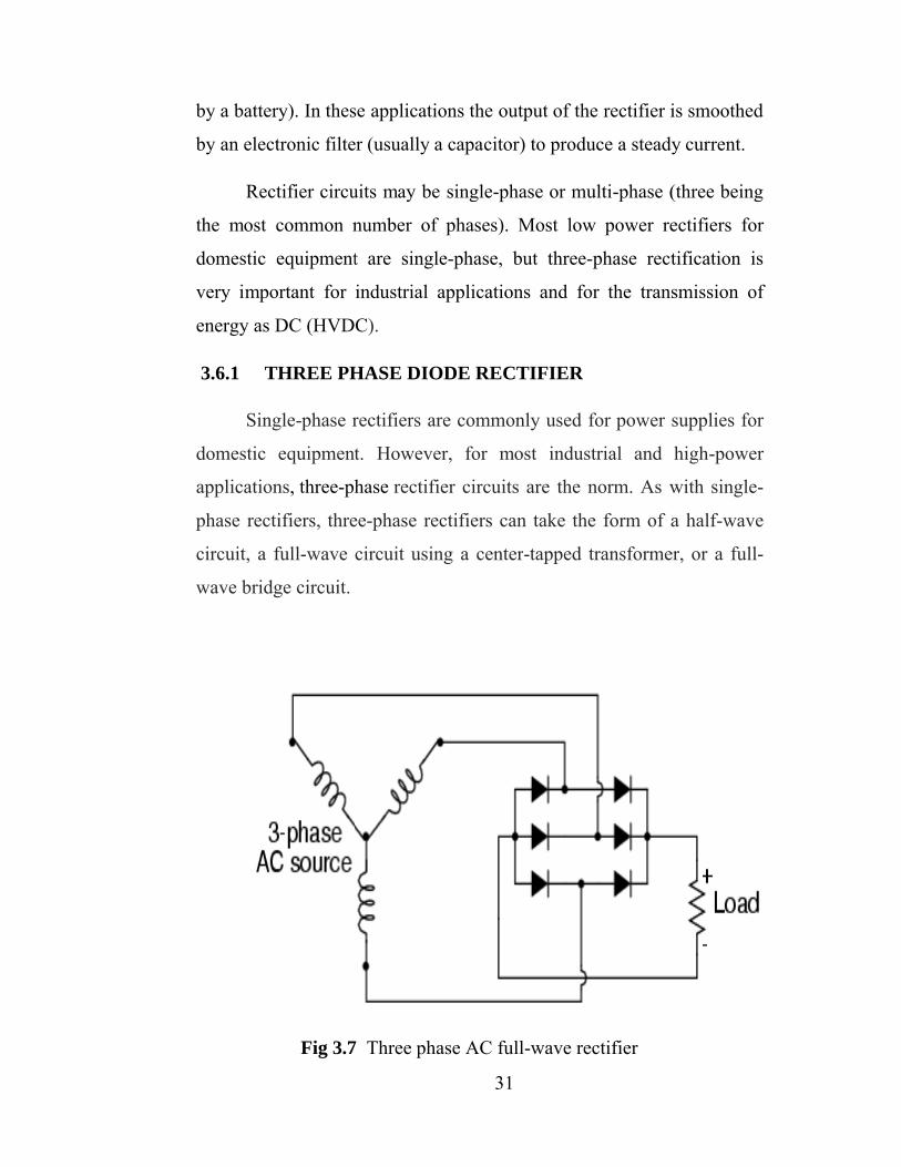
3.6.1 THREE PHASE DIODE RECTIFIER
Single-phase rectifiers are commonly used for power supplies for
domestic equipment. However, for most industrial and high
applications, three-phase
phase rectifiers, three
circuit, a full-wave circuit using a center
wave bridge circuit.
Fig 3.7
31
). In these applications the output of the rectifier is smoothed
electronic filter (usually a capacitor) to produce a steady current.
Rectifier circuits may be single-phase or multi-phase (three being
the most common number of phases). Most low power rectifiers for
domestic equipment are single-phase, but three-phase rectification is
very important for industrial applications and for the transmission of
HVDC).
HREE PHASE DIODE RECTIFIER
phase rectifiers are commonly used for power supplies for
domestic equipment. However, for most industrial and high
phase rectifier circuits are the norm. As with single
phase rectifiers, three-phase rectifiers can take the form of a half
wave circuit using a center-tapped transformer, or a full
7 Three phase AC full-wave rectifier
). In these applications the output of the rectifier is smoothed
(usually a capacitor) to produce a steady current.
phase (three being
es). Most low power rectifiers for
phase rectification is
very important for industrial applications and for the transmission of
phase rectifiers are commonly used for power supplies for
domestic equipment. However, for most industrial and high-power
rectifier circuits are the norm. As with single-
phase rectifiers can take the form of a half-wave
tapped transformer, or a full-
rectifier
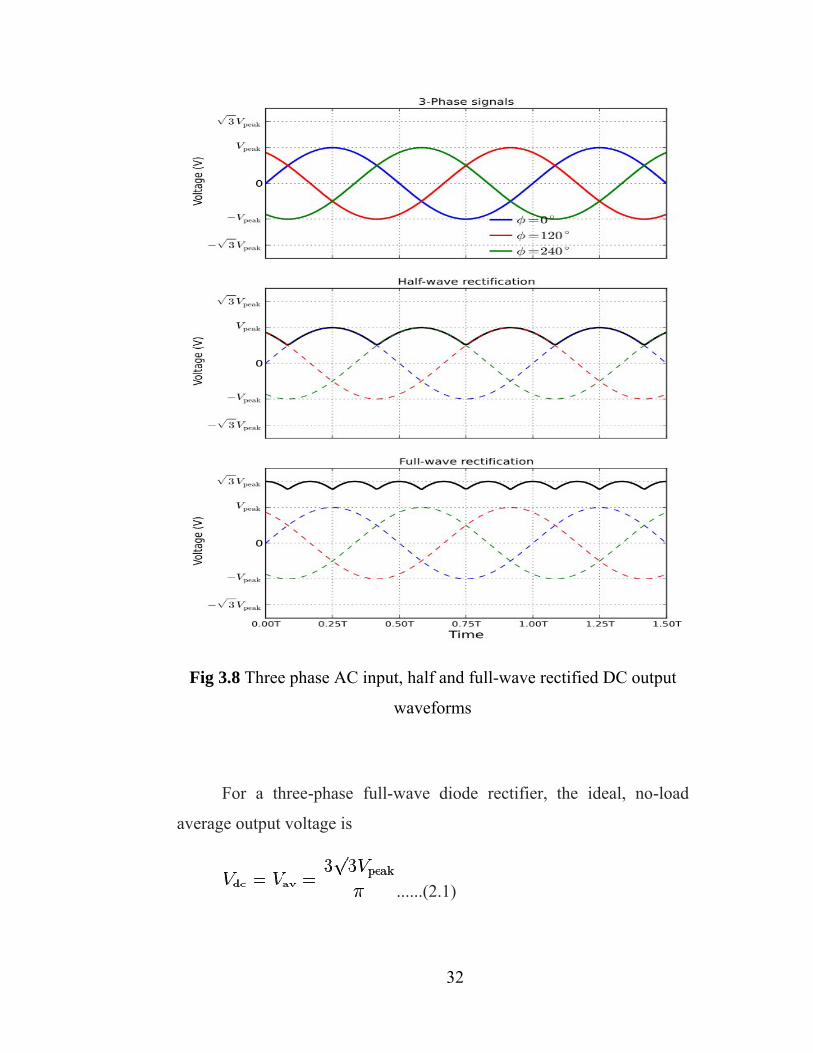
Fig 3.8 Three phase AC input, half and full
For a three-phase full
average output voltage is
32
phase AC input, half and full-wave rectified DC output
waveforms
phase full-wave diode rectifier, the ideal, no
average output voltage is
......(2.1)
wave rectified DC output
the ideal, no-load
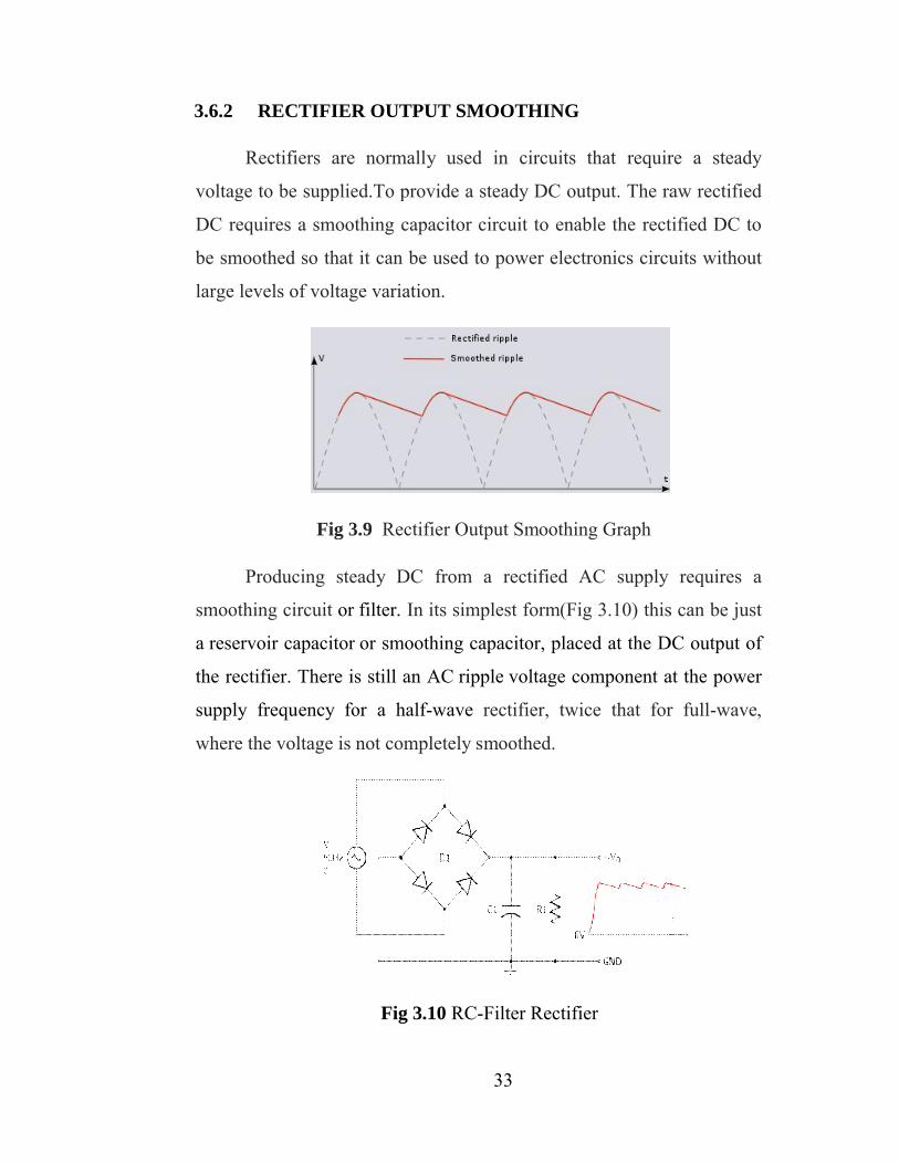
3.6.2 RECTIFIER OUTPUT SMOOTHING
Rectifiers are normally used in circuits that require a steady
voltage to be supplied.To provide a steady DC output. The raw rectified
DC requires a smoothing
be smoothed so that it can be used to power electronics circuits without
large levels of voltage variation.
Fig 3
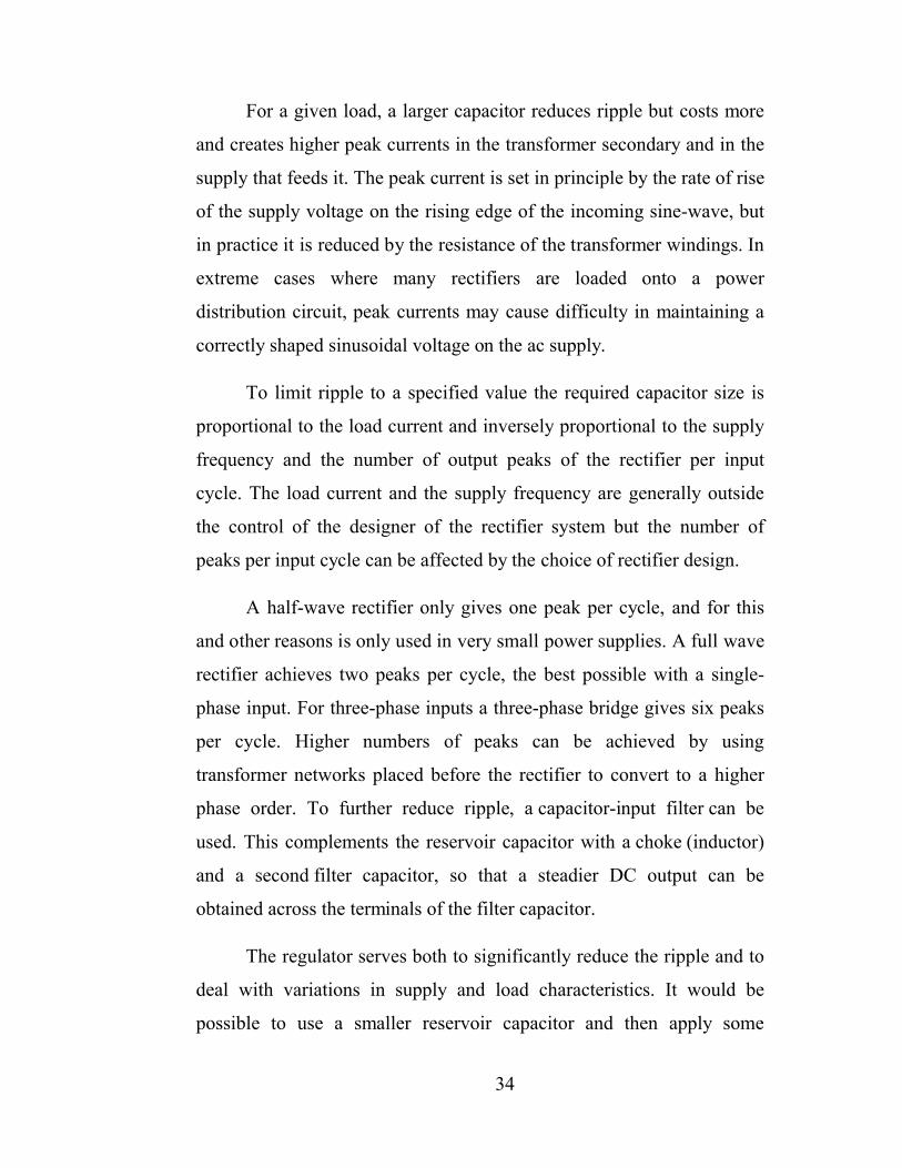
Producing steady DC from a rectified AC supply requires a
smoothing circuit or
a reservoir capacitor
the rectifier. There is still an
supply frequency for a half
where the voltage is not completely smoothed.
33
RECTIFIER OUTPUT SMOOTHING
Rectifiers are normally used in circuits that require a steady
voltage to be supplied.To provide a steady DC output. The raw rectified
DC requires a smoothing capacitor circuit to enable the rectified DC to
be smoothed so that it can be used to power electronics circuits without
large levels of voltage variation.
Fig 3.9 Rectifier Output Smoothing Graph
roducing steady DC from a rectified AC supply requires a
filter. In its simplest form(Fig 3.10) this can be just
reservoir capacitor or smoothing capacitor, placed at the DC output of
the rectifier. There is still an AC ripple voltage component at the power
supply frequency for a half-wave rectifier, twice that for full
where the voltage is not completely smoothed.
Fig 3.10 RC-Filter Rectifier
Rectifiers are normally used in circuits that require a steady
voltage to be supplied.To provide a steady DC output. The raw rectified
capacitor circuit to enable the rectified DC to
be smoothed so that it can be used to power electronics circuits without
roducing steady DC from a rectified AC supply requires a
this can be just
or smoothing capacitor, placed at the DC output of
voltage component at the power
rectifier, twice that for full-wave,
34
For a given load, a larger capacitor reduces ripple but costs more
and creates higher peak currents in the transformer secondary and in the
supply that feeds it. The peak current is set in principle by the rate of rise
of the supply voltage on the rising edge of the incoming sine-wave, but
in practice it is reduced by the resistance of the transformer windings. In
extreme cases where many rectifiers are loaded onto a power
distribution circuit, peak currents may cause difficulty in maintaining a
correctly shaped sinusoidal voltage on the ac supply.
To limit ripple to a specified value the required capacitor size is
proportional to the load current and inversely proportional to the supply
frequency and the number of output peaks of the rectifier per input
cycle. The load current and the supply frequency are generally outside
the control of the designer of the rectifier system but the number of
peaks per input cycle can be affected by the choice of rectifier design.
A half-wave rectifier only gives one peak per cycle, and for this
and other reasons is only used in very small power supplies. A full wave
rectifier achieves two peaks per cycle, the best possible with a single-
phase input. For three-phase inputs a three-phase bridge gives six peaks
per cycle. Higher numbers of peaks can be achieved by using
transformer networks placed before the rectifier to convert to a higher
phase order. To further reduce ripple, a capacitor-input filter can be
used. This complements the reservoir capacitor with a choke (inductor)
and a second filter capacitor, so that a steadier DC output can be
obtained across the terminals of the filter capacitor.
The regulator serves both to significantly reduce the ripple and to
deal with variations in supply and load characteristics. It would be
possible to use a smaller reservoir capacitor and then apply some
35
filtering as well as the regulator, but this is not a common strategy. The
extreme of this approach is to dispense with the reservoir capacitor
altogether and put the rectified waveform straight into a choke-input
filter.
The advantage of this circuit is that the current waveform is
smoother and consequently the rectifier no longer has to deal with the
current as a large current pulse, but instead the current delivery is spread
over the entire cycle. The disadvantage, apart from extra size and
weight, is that the voltage output is much lower – approximately the
average of an AC half-cycle rather than the peak.
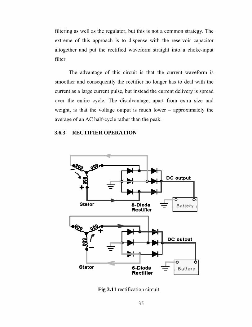
3.6.3 RECTIFIER OPERATION
Fig 3.11 rectification circuit
36
• Two diodes are connected to each stator lead. One positive the
other negative.
• Because a single diode will only block half the the AC voltage.
• Six or eight diodes are used to rectify the AC stator voltage to
DC voltage.
• Diodes used in this configuration will redirect both the positive
and negative polarity signals of the AC voltage to produce DC voltage.
This process is called ‘Full - Wave Rectification’.
At first you can see current pass through to the rectifier as it goes
to the battery. In the second, you can see the return path. Now, current
passes through to the rectifier however, this time current has the
opposite polarity. In second circuit you can see the new return path.
Even though it enters the rectifier at a different location, current goes to
the battery in the same direction.
3.7 BATTERY
Battery is essential to supply DC power for the alternator rotor
and for the storage of generated power. An electric battery is a device
consisting of one or more electrochemical cells that convert stored
chemical energy into electrical energy. Each cell contains a positive
terminal, or cathode, and a negative terminal, or anode. Electrolytes
allow ions to move between the electrodes and terminals, which allows
current to flow out of the battery to perform work. Battery we used is
12V, 10 Ah rating.
The battery is a two-terminal device that provides DC supply to
the inverter section when the AC mains are not available. This DC is
then converted into 220V AC supply and output at the inverter output
37
socket. It is pertinent to state that lead-acid batteries used in automobiles
are very good for this purpose as they provide good quality power for a
long duration and can be recharged once the power stored in them are
consumed. The backup time provided by the inverter depends on the
battery type and its current capacity
Primary (single-use or "disposable") batteries are used once and
discarded; the electrode materials are irreversibly changed during
discharge. Common examples are the alkaline battery used
for flashlights and a multitude of portable devices.
Secondary (rechargeable batteries) can be discharged and recharged
multiple times; the original composition of the electrodes can be restored
by reverse current. Examples include the lead-acid batteries used in
vehicles and lithium ion batteries used for portable electronics.
The battery was selected based on the amount of time we wanted
to operate the system at full load. As mentioned in the specifications, we
wanted to be able to power the lights. Fulfilling the 12 V DC battery
requirements, we found a unit from Universal Battery with 18 Ah. If the
battery is discharged to 50% at most, this battery leaves us with 9 Ah.
Our load of lighting, music, and an iPod charger uses about 20
watts, but with an alternative appliance connected (e.g. phone), the total
power consumed could be estimated at 25 watts. With a 12 VDC battery
and a 25 W load, we have about 2 A of current, which gives us about 4.5
hours of use at full load – this is consistent with our design
specifications. The exact battery we selected is UB12180 (12V 10Ah).
An electric battery is a device consisting of one or more electrochemical
cells that convert stored chemical energy into electrical energy. Each cell
contains a positive terminal, or cathode, and a negative terminal,
38
or anode. Electrolytes allow ions to move between the electrodes and
terminals, which allows current to flow out of the battery to perform
work.
A lead-acid battery charger is most popular though it will very
large size than others battery type. But them have advantage are : cheap,
easy to buy and long life if correctly uses.
3.7.1 BATTERY CHARGER
A battery charger is a device used to put energy into a cell or
(rechargeable) battery by forcing an electric current through it. Lead-
acid battery chargers typically have two tasks to accomplish. The first is
to restore capacity, often as quickly as practical. The second is to
maintain capacity by compensating for self discharge.
In both instances optimum operation requires accurate sensing of
battery voltage. When a typical lead-acid cell is charged, lead sulphate is
converted to lead on the battery’s negative plate and lead dioxide on the
positive plate. Over-charge reactions begin when the majority of lead
sulphate has been converted, typically resulting in the generation of
hydrogen and oxygen gas. At moderate charge rates, most of the
hydrogen and oxygen will recombine in sealed batteries. In unsealed
batteries however, dehydration will occur. The onset of over-charge can
be detected by monitoring battery voltage.
Over charge reactions are indicated by the sharp rise in cell
voltage. The point at which over-charge reactions begin is dependent on
charge rate, and as charge rate is increased, the percentage of returned
capacity at the onset of over-charge diminishes. For overcharge to
coincide with 100% return of capacity, the charge rate must typically be
less than 1/100 amps of its amp- hour capacity. At high charge rates,
39
controlled over-charging is typically as quickly as possible. To maintain
capacity on a fully charged battery, a constant voltage is applied. The
voltage must be high enough to compensate for self discharge, yet not
too high as to cause excessive over-charging.
3.7.2 CHARGING AND DISCHARGING OF BATTERY
Charging a lead acid battery is a matter of replenishing the
depleted supply of energy that the battery had lost during use. This
replenishing process can be accomplished with several different charger
implementations: “constant voltage charger”, “constant current charger”
or a “multistage" constant voltage/current charger. Each of these
approaches has its advantages and disadvantages that need to be
compared and weighed to see which one would be the most practical and
realistic to fit with our requirements.
Constant voltage charging is one of the most common charging
methods for lead acid batteries. The idea behind this approach is to keep
a constant voltage across the terminals of the battery at all times.
Initially, a large current will be drawn from the voltage source, but as the
battery charges and increases its internal voltage, the current will slowly
fold and decays exponentially.
When the battery is brought up to a potential full charge, which is
usually considered around 13.8V, the charging voltage is dropped down
to a lower value that will provide a trickle charge to maintain the battery
as long as it is plugged into the charger.
The best characteristic of this method is that it provides a way to
return a large bulk of the charge into the battery very fast. The drawback
is that to complete a full charge would take a much longer time since the
current is exponentially decreased as the battery charges. A prolonged
40
charging time must be considered as one of the issues to this design.
Constant current charging is another simple yet effective method for
charging lead acid batteries.
A current source is used to drive a uniform current through the
battery in a direction opposite of discharge. This can be analogous to
pouring water into a bucket with a constant water flow, no matter how
full the bucket is. Constant current sources are not very hard to
implement; therefore, the final solution would require a very simple
design.
There is a major drawback to this approach. Since the battery is
always being pushed at a constant rate, when it is close to being fully
charged, the charger would force extra current into the battery, causing
overcharge. The ability to harness this current is the key to a successful
charger. By monitoring the voltage on the battery, the charge level can
be determined, and at a certain point, the current source would need to
be folded back to only maintain a trickle charge and prevent
overcharging.
When the battery is connected to the external load, the chemical
changes take place in reverse direction, during which the absorbed
energy is released as electrical energy and supplied to the load. Thus the
12V DC output of the battery is fed to the MOSFET inverter.
3.8 INVERTER
The inverter should be chosen so that its input voltage matches
that of the storage battery. Fortunately, most inverters are designed to
operate at about 12V in order to function with standard lead-acid
batteries.
41
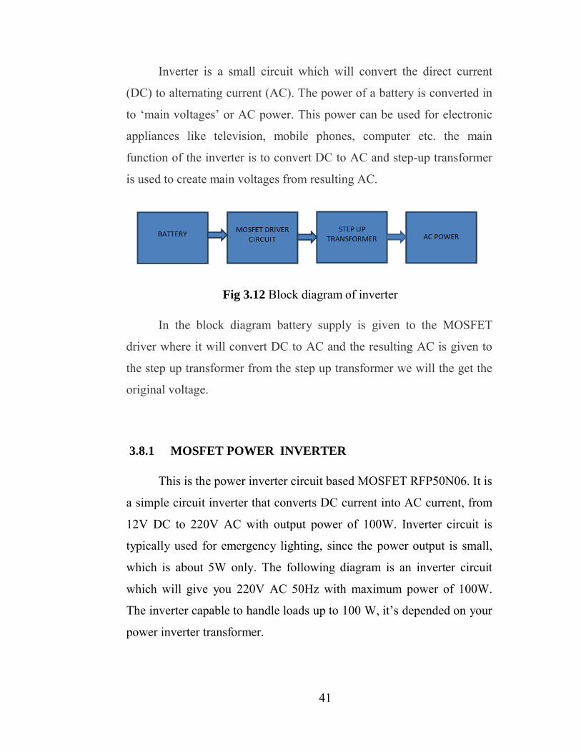
Inverter is a small circuit which will convert the direct current
(DC) to alternating current (AC). The power of a battery is converted in
to ‘main voltages’ or AC power. This power can be used for electronic
appliances like television, mobile phones, computer etc. the main
function of the inverter is to convert DC to AC and step-up transformer
is used to create main voltages from resulting AC.
Fig 3.12 Block diagram of inverter
In the block diagram battery supply is given to the MOSFET
driver where it will convert DC to AC and the resulting AC is given to
the step up transformer from the step up transformer we will the get the
original voltage.
3.8.1 MOSFET POWER INVERTER
This is the power inverter circuit based MOSFET RFP50N06. It is
a simple circuit inverter that converts DC current into AC current, from
12V DC to 220V AC with output power of 100W. Inverter circuit is
typically used for emergency lighting, since the power output is small,
which is about 5W only. The following diagram is an inverter circuit
which will give you 220V AC 50Hz with maximum power of 100W.
The inverter capable to handle loads up to 100 W, it’s depended on your
power inverter transformer.
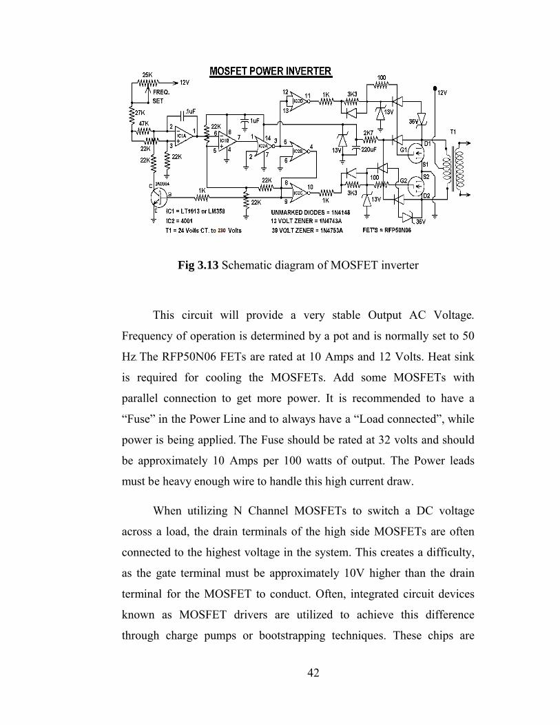
Fig 3.13
This circuit will provide a very stable Output AC Voltage.
Frequency of operation is determined by a pot and is normally set to 50
Hz. The RFP50N06 FETs are rated at 10 Amps and 12
is required for coo
parallel connection to get more power. It is recommended to have a
“Fuse” in the Power Line and to always have a “Load connected”, while
power is being applied
be approximately 10 Amps per 100 watts of output. The Power leads
must be heavy enough wire
When utilizing N
across a load, the drain terminals of the high side MOSFETs are often
connected to the highest voltage in the system. This creates a difficulty,
as the gate terminal must be approximately 10V higher than the drain
terminal for the MOSFET to conduct. Often, integrated circuit devices
known as MOSFET drivers are utilized to achieve this difference
through charge pumps or bootstrapping techniques. These chips are
42
Schematic diagram of MOSFET inverter
This circuit will provide a very stable Output AC Voltage.
Frequency of operation is determined by a pot and is normally set to 50
FETs are rated at 10 Amps and 12 Volts. Heat sink
is required for cooling the MOSFETs. Add some MOSFETs with
parallel connection to get more power. It is recommended to have a
“Fuse” in the Power Line and to always have a “Load connected”, while
power is being applied. The Fuse should be rated at 32 volts and should
oximately 10 Amps per 100 watts of output. The Power leads
must be heavy enough wire to handle this high current draw.
When utilizing N Channel MOSFETs to switch a DC voltage
across a load, the drain terminals of the high side MOSFETs are often
connected to the highest voltage in the system. This creates a difficulty,
as the gate terminal must be approximately 10V higher than the drain
minal for the MOSFET to conduct. Often, integrated circuit devices
known as MOSFET drivers are utilized to achieve this difference
through charge pumps or bootstrapping techniques. These chips are
Schematic diagram of MOSFET inverter
This circuit will provide a very stable Output AC Voltage.
Frequency of operation is determined by a pot and is normally set to 50
Volts. Heat sink
d some MOSFETs with
parallel connection to get more power. It is recommended to have a
“Fuse” in the Power Line and to always have a “Load connected”, while
The Fuse should be rated at 32 volts and should
oximately 10 Amps per 100 watts of output. The Power leads
Channel MOSFETs to switch a DC voltage
across a load, the drain terminals of the high side MOSFETs are often
connected to the highest voltage in the system. This creates a difficulty,
as the gate terminal must be approximately 10V higher than the drain
minal for the MOSFET to conduct. Often, integrated circuit devices
known as MOSFET drivers are utilized to achieve this difference
through charge pumps or bootstrapping techniques. These chips are
43
capable of quickly charging the input capacitance of the MOSFET
quickly before the potential difference is reached, causing the gate to
source voltage to be the highest system voltage plus the capacitor
voltage, allowing it to conduct.
There are many MOSFET drivers available to power N Channel
MOSFETs through level translation of low voltage control signals into
voltages capable of supplying sufficient gate voltage. Advanced drivers
contain circuitry for powering high and low side devices as well as N
and P Channel MOSFETs. In this design, all MOSFETs are N Channel
due to their increased current handling capabilities.
To overcome the difficulties of driving high side N Channel
MOSFETs, the driver devices use an external source to charge a
bootstrapping capacitor connected between Vcc and source terminals.
The bootstrap capacitor provides gate charge to the high side MOSFET.
As the switch begins to conduct, the capacitor maintains a potential
difference, rapidly causing the MOSFET to further conduct, until it is
fully on. The name bootstrap component refers to this process and how
the MOSFET acts as if it is “pulling itself up by its own boot strap”.
Main components are:
IC LT4013 is basically made up of two D-type flip flop modules
and set/reset asynchronous toggle inputs. As the name suggests, the IC is
primarily used as a bistable for toggling the output stage of a particular
circuit, and it is fundamentally incorporated in most electronic circuits.
IC 4001is the most commonly used Complementary Metal Oxide
Semiconductor (CMOS) chip. It comes in a 14 pin Dual Inline Package
(DIP). It has small notch on one side which is identified as pin 1.It
consists of 4 independent NOR gate in a single chip. Each gate has 2
44
inputs and 1 output. Working voltage range of IC is from 5V to 15V. It
can deliver approx.10mA at 12V but this can be reduced as power
supply voltage reduces.
IC LM4001 along with IC4013 and the transistor form a voltage
controlled oscillator of which the frequency is adjusted with the
25Kohmpot. The 13 volt Zener stabilize supply voltages and limit
signals, while the 36 volt Zener limit spikes from the transformer.
3.8.2 WORKING OF MOSFET POWER INVERTER
The AC input supplies a 220V AC, 50Hz from the public supply.
This is connected to the charger circuit where it is rectified to DC
voltage and through the relay switch to the output of the inverter to
bypass the inverter when there is public electric power supply while the
battery is charging.
This inverter uses a 0 – 12 V/1Amp triggering transformer and a
regulator to sense the AC mains supply. When the AC mains supply is
available, this supply is given to the primary winding of the triggering
transformer to give 12V AC supply at the secondary winding. It is then
rectified by bridge rectifier and input to filter capacitors which convert
the 18V supply to 12V DC supply. The 12V supply stays constant even
when there is a change in the AC mains supply and the inverter is
informed about the availability of the AC mains supply.
The Oscillator, a pulse width modulator PMW IC SG 3524 to
generate the 50Hz frequency required to generate AC supply by the
inverter.
45
The battery supply is connected to the IC SG 3524 through the
inverter ON/OFF switch. The flip-flop converts the incoming signal into
signals with changing polarity such that in a two-signal with changing
polarity, the first is positive while the second is negative and vice versa.
This process is repeated 50times per second to give an alternating signal
with 50Hz frequency at the output of SG3524. This alternating signal is
known as "MOS Drive Signal ".
The MOS drive signals are given to the base of MOS driver
transistor which results in the MOS drive signal getting separated into
two different channels. The transistors amplify the 50Hz MOS drive
signal at their base to a sufficient level and output them from the emitter.
The 50Hz signal from the emitter of each of the transistor is connected
to the gate G of all the MOSFETS in each of the MOSFET channel,
through the appropriate resistance.
The battery charger hen the inverter section receives AC mains
supply, it stops operation but the charger section in the inverter starts its
operation. In this mode, the inverter transformer works as a step down
transformer and output 12V at its secondary winding.
During the charging, MOSFET transistors at the output section
works as rectifier with the drain working as the cathode while the source
works as the anode. The center-tapping of the transformer receives
positive supply and the MOSFET source 'S' receives negative supply
from the battery. The center-tapping is connected to the positive terminal
of the battery and the MOSFET source S is connected to the negative
terminal with a shunt resistance. Thus, when the inverter receives AC
mains supply, inverter transformer and MOSFET together work as a
charger and charge the battery.
46
The change over section is used to switch ON the inverter when
the AC mains supply is OFF and to switch OFF the inverter when the
AC mains supply returns (ON).
During changeover, when the inverter receives AC mains supply,
it stops drawing the battery supply and the AC mains supply at the
inverter input is directly sent to the inverter output socket. This is done
using a one, two-pole relay.
The AC output gives a 220V AC, 50Hz either directly from the
input when the AC mains supply is available or from the inverter circuit
action on the battery when the AC mains supply is not available.
Computers and other household appliances are connected to this output.
The AC input to this device was fused with a 5A fuse to protect
the transformer as well as the rectifying circuit in case of over voltage,
and high current which could flow into the transformer.
This AC is given to the step up transformer of the secondary coil
from this coil only we will get the increased AC voltage , this AC
voltage is so high; from step up transformer we will get the max voltage.
Zener diode will help avoid the reverse current.
The generated AC is not equal to the normal AC mains or house
hold current. You cannot use this voltage for pure electric appliances
like heater, electric cooker etc. Because of the fast switching of
MOSFETs heat is dissipated which will effect the efficiency, use heat
sink to remove this problem.
The output voltage of the inverter was a square wave, filtered by a
2µF/400V capacitor connected across the output terminals to remove the
unwanted harmonics and leaving smooth sine waveform output voltage.
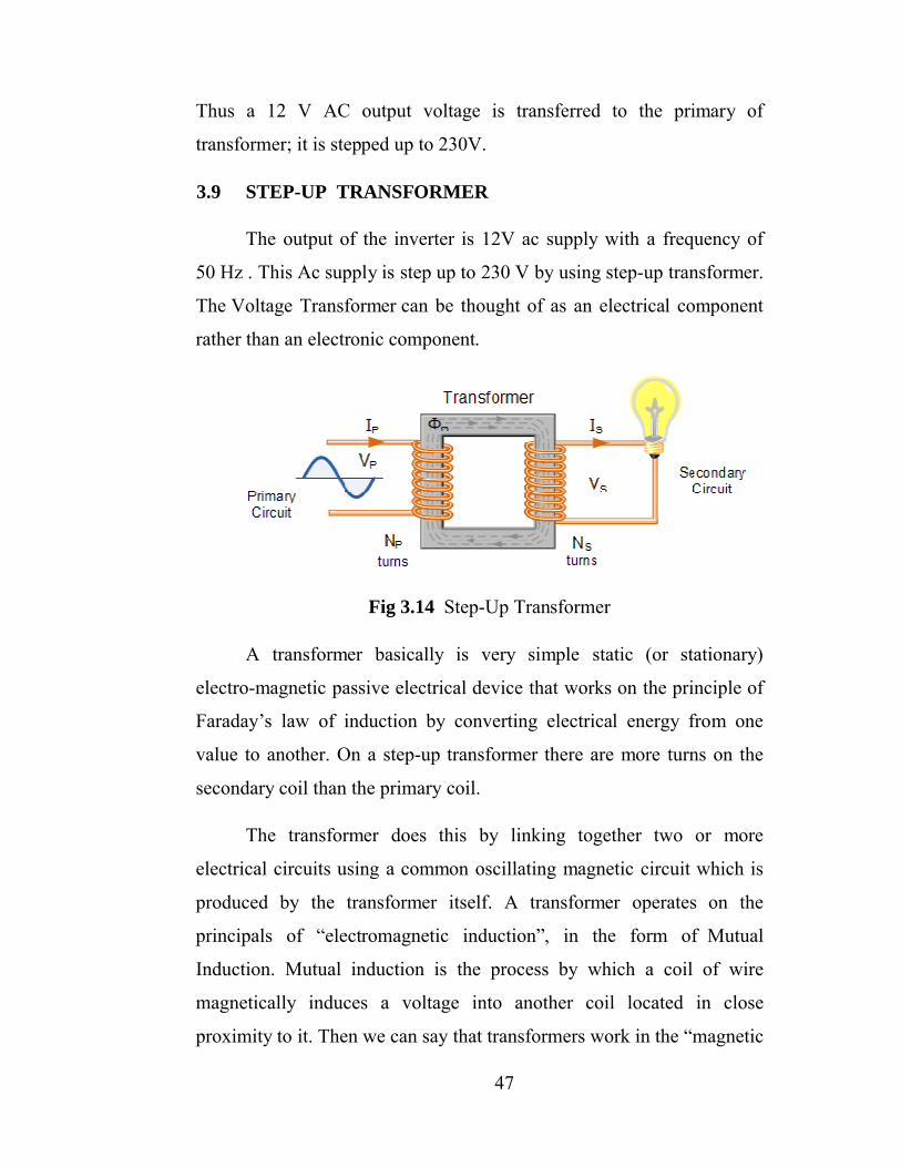
47
Thus a 12 V AC output voltage is transferred to the primary of
transformer; it is stepped up to 230V.
3.9 STEP-UP TRANSFORMER
The output of the inverter is 12V ac supply with a frequency of
50 Hz . This Ac supply is step up to 230 V by using step-up transformer.
The Voltage Transformer can be thought of as an electrical component
rather than an electronic component.
Fig 3.14 Step-Up Transformer
A transformer basically is very simple static (or stationary)
electro-magnetic passive electrical device that works on the principle of
Faraday’s law of induction by converting electrical energy from one
value to another. On a step-up transformer there are more turns on the
secondary coil than the primary coil.
The transformer does this by linking together two or more
electrical circuits using a common oscillating magnetic circuit which is
produced by the transformer itself. A transformer operates on the
principals of “electromagnetic induction”, in the form of Mutual
Induction. Mutual induction is the process by which a coil of wire
magnetically induces a voltage into another coil located in close
proximity to it. Then we can say that transformers work in the “magnetic
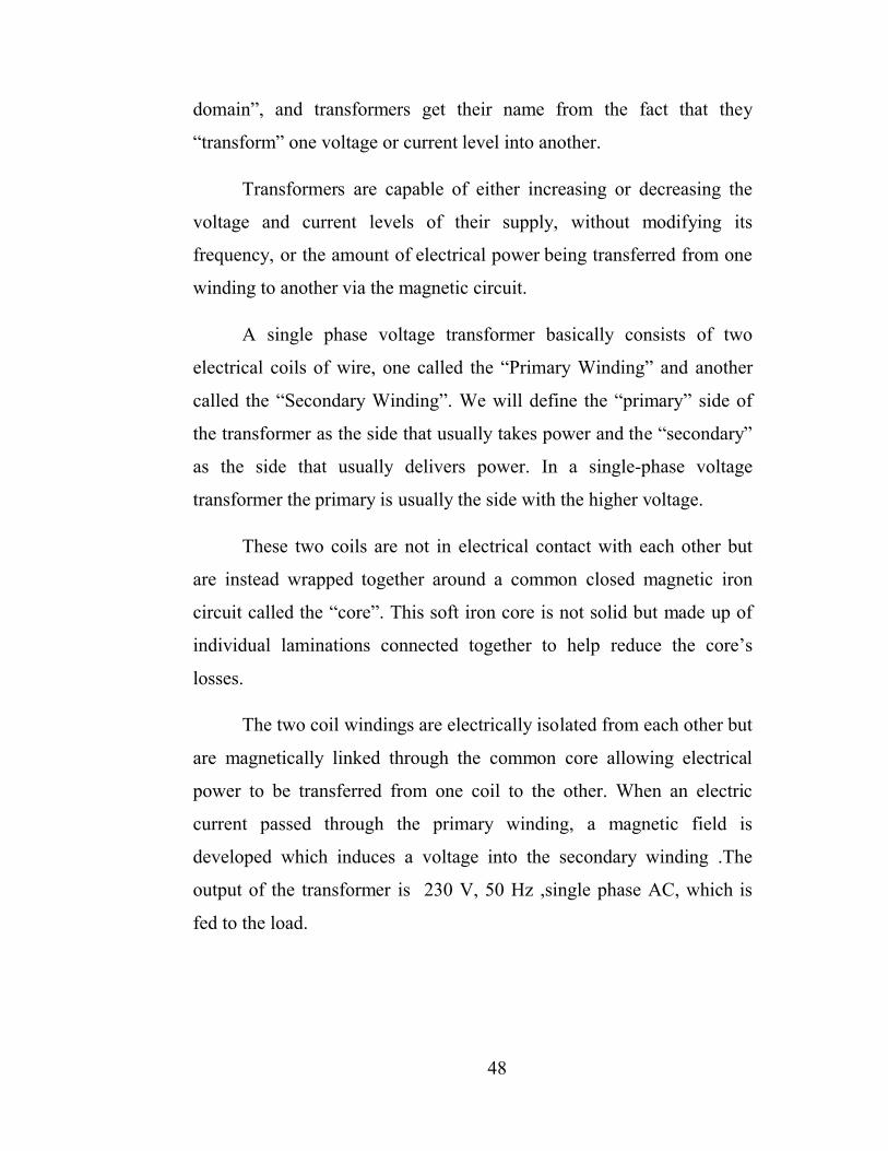
48
domain”, and transformers get their name from the fact that they
“transform” one voltage or current level into another.
Transformers are capable of either increasing or decreasing the
voltage and current levels of their supply, without modifying its
frequency, or the amount of electrical power being transferred from one
winding to another via the magnetic circuit.
A single phase voltage transformer basically consists of two
electrical coils of wire, one called the “Primary Winding” and another
called the “Secondary Winding”. We will define the “primary” side of
the transformer as the side that usually takes power and the “secondary”
as the side that usually delivers power. In a single-phase voltage
transformer the primary is usually the side with the higher voltage.
These two coils are not in electrical contact with each other but
are instead wrapped together around a common closed magnetic iron
circuit called the “core”. This soft iron core is not solid but made up of
individual laminations connected together to help reduce the core’s
losses.
The two coil windings are electrically isolated from each other but
are magnetically linked through the common core allowing electrical
power to be transferred from one coil to the other. When an electric
current passed through the primary winding, a magnetic field is
developed which induces a voltage into the secondary winding .The
output of the transformer is 230 V, 50 Hz ,single phase AC, which is
fed to the load.
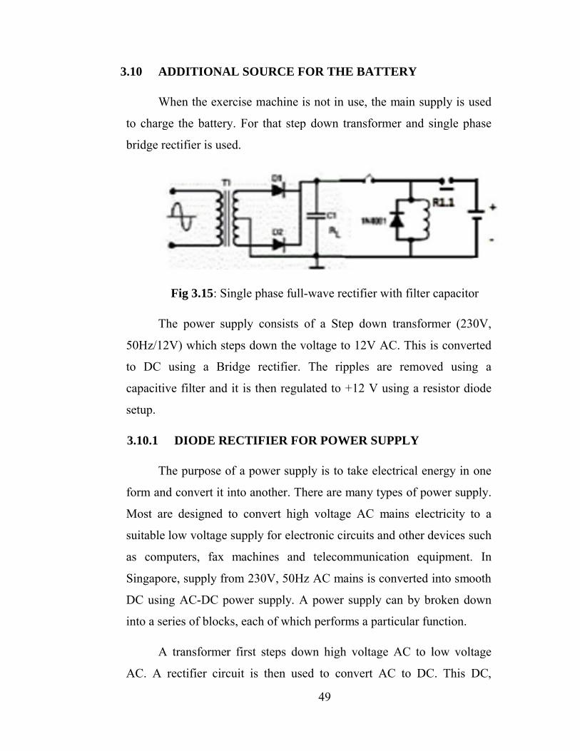
3.10 ADDITIONAL SOURCE FOR THE BATTERY
When the exercise machine is not in use, the main supply is used
to charge the battery.
bridge rectifier is used
Fig 3.15: Single phase f
The power supply consists of a Step down transformer (230V,
50Hz/12V) which steps down the voltage to 12V AC. This is converted
to DC using a Bridge rectifier. The ripples are removed using a
capacitive filter and it is then regulated to +12 V us
setup.
3.10.1 DIODE RECTIFIER FOR POWER SUPPLY
The purpose of a power supply is to take electrical energy in one
form and convert it into another. There are many types of power supply.
Most are designed to convert high voltage AC mains elect
suitable low voltage supply for electronic circuits and other devices such
as computers, fax machines and
Singapore, supply from 230V, 50Hz AC mains is converted into smooth
DC using AC-DC power supply. A power s
into a series of blocks, each of which performs a particular function.
A transformer first steps down high voltage AC to low voltage
AC. A rectifier circuit is then used to convert AC to DC. This DC,
49
TIONAL SOURCE FOR THE BATTERY
When the exercise machine is not in use, the main supply is used
to charge the battery. For that step down transformer and single phase
bridge rectifier is used.
Single phase full-wave rectifier with filter
The power supply consists of a Step down transformer (230V,
50Hz/12V) which steps down the voltage to 12V AC. This is converted
to DC using a Bridge rectifier. The ripples are removed using a
capacitive filter and it is then regulated to +12 V using a resistor diode
DIODE RECTIFIER FOR POWER SUPPLY
The purpose of a power supply is to take electrical energy in one
form and convert it into another. There are many types of power supply.
Most are designed to convert high voltage AC mains elect
suitable low voltage supply for electronic circuits and other devices such
as computers, fax machines and telecommunication equipment. In
Singapore, supply from 230V, 50Hz AC mains is converted into smooth
DC power supply. A power supply can by broken down
into a series of blocks, each of which performs a particular function.
A transformer first steps down high voltage AC to low voltage
AC. A rectifier circuit is then used to convert AC to DC. This DC,
When the exercise machine is not in use, the main supply is used
For that step down transformer and single phase
wave rectifier with filter capacitor
The power supply consists of a Step down transformer (230V,
50Hz/12V) which steps down the voltage to 12V AC. This is converted
to DC using a Bridge rectifier. The ripples are removed using a
ing a resistor diode
The purpose of a power supply is to take electrical energy in one
form and convert it into another. There are many types of power supply.
Most are designed to convert high voltage AC mains electricity to a
suitable low voltage supply for electronic circuits and other devices such
telecommunication equipment. In
Singapore, supply from 230V, 50Hz AC mains is converted into smooth
upply can by broken down
into a series of blocks, each of which performs a particular function.
A transformer first steps down high voltage AC to low voltage
AC. A rectifier circuit is then used to convert AC to DC. This DC,
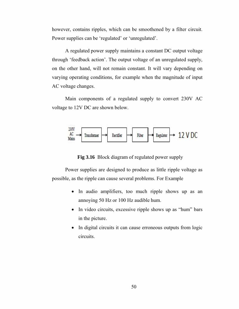
50
however, contains ripples, which can be smoothened by a filter circuit.
Power supplies can be ‘regulated’ or ‘unregulated’.
A regulated power supply maintains a constant DC output voltage
through ‘feedback action’. The output voltage of an unregulated supply,
on the other hand, will not remain constant. It will vary depending on
varying operating conditions, for example when the magnitude of input
AC voltage changes.
Main components of a regulated supply to convert 230V AC
voltage to 12V DC are shown below.
Fig 3.16 Block diagram of regulated power supply
Power supplies are designed to produce as little ripple voltage as
possible, as the ripple can cause several problems. For Example
In audio amplifiers, too much ripple shows up as an
annoying 50 Hz or 100 Hz audible hum.
In video circuits, excessive ripple shows up as “hum” bars
in the picture.
In digital circuits it can cause erroneous outputs from logic
circuits.
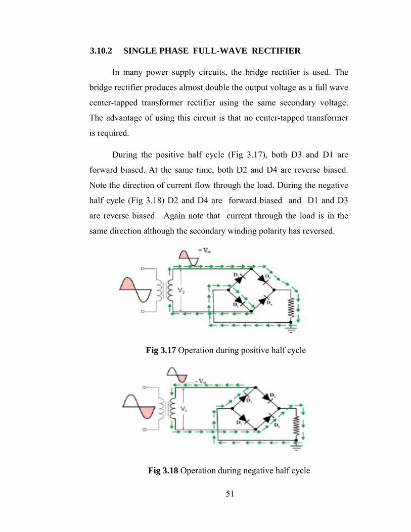
51
3.10.2 SINGLE PHASE FULL-WAVE RECTIFIER
In many power supply circuits, the bridge rectifier is used. The
bridge rectifier produces almost double the output voltage as a full wave
center-tapped transformer rectifier using the same secondary voltage.
The advantage of using this circuit is that no center-tapped transformer
is required.
During the positive half cycle (Fig 3.17), both D3 and D1 are
forward biased. At the same time, both D2 and D4 are reverse biased.
Note the direction of current flow through the load. During the negative
half cycle (Fig 3.18) D2 and D4 are forward biased and D1 and D3
are reverse biased. Again note that current through the load is in the
same direction although the secondary winding polarity has reversed.
Fig 3.17 Operation during positive half cycle
Fig 3.18 Operation during negative half cycle
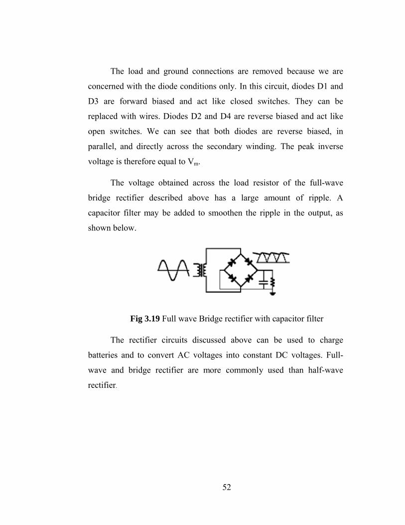
52
The load and ground connections are removed because we are
concerned with the diode conditions only. In this circuit, diodes D1 and
D3 are forward biased and act like closed switches. They can be
replaced with wires. Diodes D2 and D4 are reverse biased and act like
open switches. We can see that both diodes are reverse biased, in
parallel, and directly across the secondary winding. The peak inverse
voltage is therefore equal to Vm.
The voltage obtained across the load resistor of the full-wave
bridge rectifier described above has a large amount of ripple. A
capacitor filter may be added to smoothen the ripple in the output, as
shown below.
Fig 3.19 Full wave Bridge rectifier with capacitor filter
The rectifier circuits discussed above can be used to charge
batteries and to convert AC voltages into constant DC voltages. Full-
wave and bridge rectifier are more commonly used than half-wave
rectifier.

53
CHAPTER-4
IMPLEMENTATION AND RESULT
4.1 KEY REQUIREMENTS
The safety test is the most crucial aspect of the test plan and each
stage of the design must pass the safety test before moving on. The
safety is important to three elements of the design. The project is
designed for people who use this on a daily basis and safety evaluations
need to ensure nothing will compromise the user’s safety. After all,
something healthy such as exercising should not turn into something
unhealthy. The second element of the safety test is for the servicing of
the design. This means that the project should not discharge or bring
harm to the person working on the design. This project is being
developed to save the user energy and money..
The efficiency of each component needs to be as high as possible.
The method of determining efficiency was different for each subsystem.
For the generator, it requires high conversion efficiency from
mechanical energy into electrical energy. The microprocessor needs to
have the least amount of processing time as possible and this means
streamlining the code as much as possible but maintaining the basic
functional requirements. A high efficiency is required for each
component to get the maximum result from the entire design which will
translate into more energy and more money saved.
The implementation capabilities apply mainly to the aesthetics
and marketability of the design. The design needs to be compact enough
to be used at home next to the elliptical but also durable enough to be
used regularly at popular fitness centers.
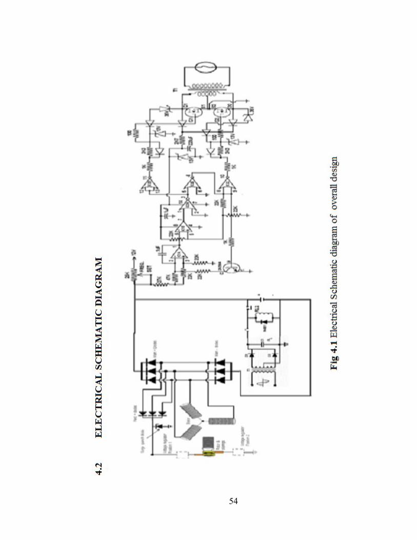
54
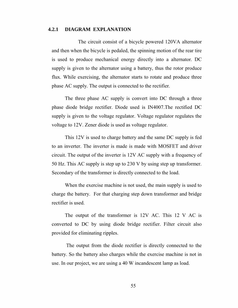
55
4.2.1 DIAGRAM EXPLANATION
The circuit consist of a bicycle powered 120VA alternator
and then when the bicycle is pedaled, the spinning motion of the rear tire
is used to produce mechanical energy directly into a alternator. DC
supply is given to the alternator using a battery, thus the rotor produce
flux. While exercising, the alternator starts to rotate and produce three
phase AC supply. The output is connected to the rectifier.
The three phase AC supply is convert into DC through a three
phase diode bridge rectifier. Diode used is IN4007.The rectified DC
supply is given to the voltage regulator. Voltage regulator regulates the
voltage to 12V. Zener diode is used as voltage regulator.
This 12V is used to charge battery and the same DC supply is fed
to an inverter. The inverter is made is made with MOSFET and driver
circuit. The output of the inverter is 12V AC supply with a frequency of
50 Hz. This AC supply is step up to 230 V by using step up transformer.
Secondary of the transformer is directly connected to the load.
When the exercise machine is not used, the main supply is used to
charge the battery. For that charging step down transformer and bridge
rectifier is used.
The output of the transformer is 12V AC. This 12 V AC is
converted to DC by using diode bridge rectifier. Filter circuit also
provided for eliminating ripples.
The output from the diode rectifier is directly connected to the
battery. So the battery also charges while the exercise machine is not in
use. In our project, we are using a 40 W incandescent lamp as load.
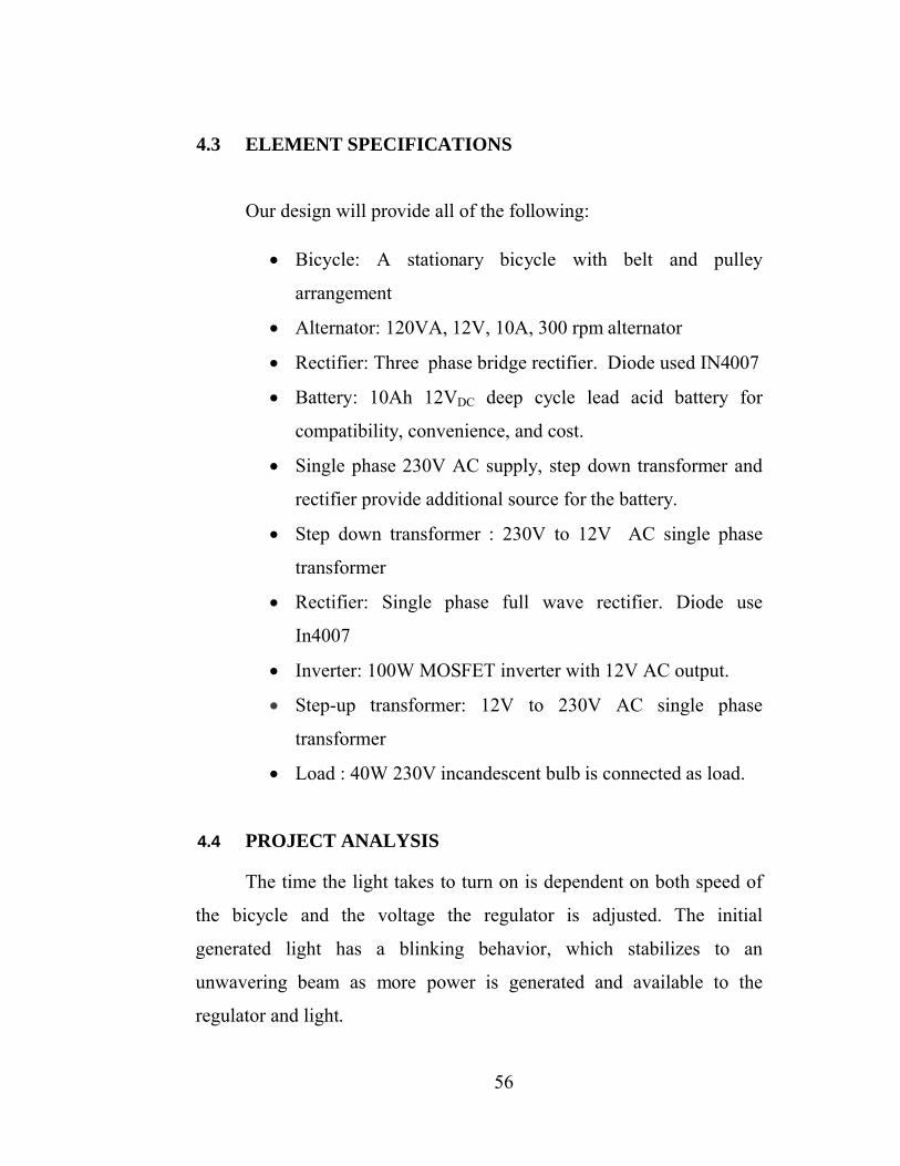
56
4.3 ELEMENT SPECIFICATIONS
Our design will provide all of the following:
Bicycle: A stationary bicycle with belt and pulley
arrangement
Alternator: 120VA, 12V, 10A, 300 rpm alternator
Rectifier: Three phase bridge rectifier. Diode used IN4007
Battery: 10Ah 12VDC deep cycle lead acid battery for
compatibility, convenience, and cost.
Single phase 230V AC supply, step down transformer and
rectifier provide additional source for the battery.
Step down transformer : 230V to 12V AC single phase
transformer
Rectifier: Single phase full wave rectifier. Diode use
In4007
Inverter: 100W MOSFET inverter with 12V AC output.
Step-up transformer: 12V to 230V AC single phase
transformer
Load : 40W 230V incandescent bulb is connected as load.
4.4 PROJECT ANALYSIS
The time the light takes to turn on is dependent on both speed of
the bicycle and the voltage the regulator is adjusted. The initial
generated light has a blinking behavior, which stabilizes to an
unwavering beam as more power is generated and available to the
regulator and light.
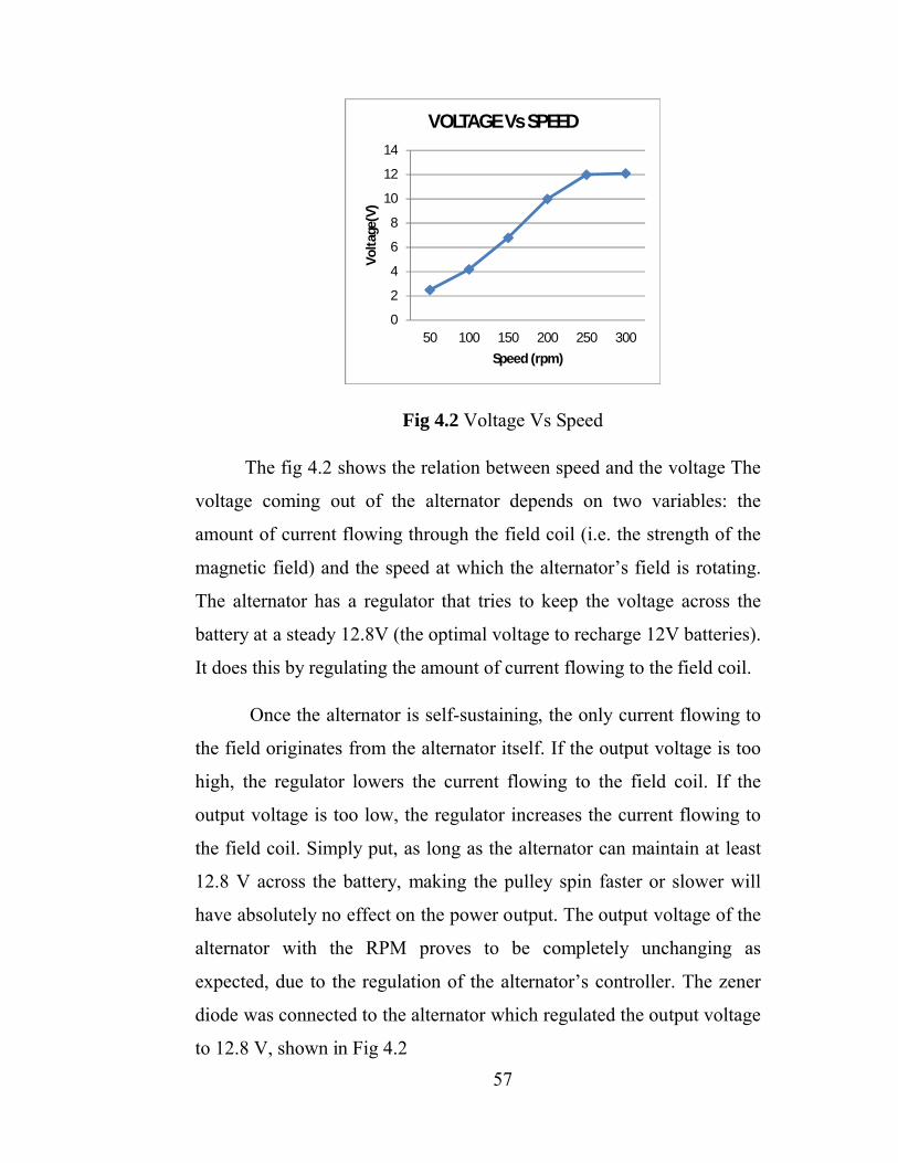
57
Fig 4.2 Voltage Vs Speed
The fig 4.2 shows the relation between speed and the voltage The
voltage coming out of the alternator depends on two variables: the
amount of current flowing through the field coil (i.e. the strength of the
magnetic field) and the speed at which the alternator’s field is rotating.
The alternator has a regulator that tries to keep the voltage across the
battery at a steady 12.8V (the optimal voltage to recharge 12V batteries).
It does this by regulating the amount of current flowing to the field coil.
Once the alternator is self-sustaining, the only current flowing to
the field originates from the alternator itself. If the output voltage is too
high, the regulator lowers the current flowing to the field coil. If the
output voltage is too low, the regulator increases the current flowing to
the field coil. Simply put, as long as the alternator can maintain at least
12.8 V across the battery, making the pulley spin faster or slower will
have absolutely no effect on the power output. The output voltage of the
alternator with the RPM proves to be completely unchanging as
expected, due to the regulation of the alternator’s controller. The zener
diode was connected to the alternator which regulated the output voltage
to 12.8 V, shown in Fig 4.2
0
2
4
6
8
10
12
14
50 100 150 200 250 300
Volta
ge(V
)Speed (rpm)
VOLTAGE Vs SPEED
58
Fig 4.3 Current Vs Speed
The current of the alternator with the speed of the cycle (similar to
alternator speed) is shown in the Fig 4.3 .The output current is minimum
until around 300 rpm. Once that rpm rate is surpassed, the output current
increase according to the load connected
4.5 RESULT
We construct innovative exercise equipment for generating
electricity. By using bicycle, alternator, inverter, battery, step up and
step down transformer, rectifier circuit and incandescent lamp. We
successfully take the 230 V single phase 50 Hz output supply and it is
used to light 40W incandescent lamp. When the exercise machine is not
used, the main supply is used to charge the battery. So the battery also
charges while the exercise machine is not in use. So provide a
continuous supply.
0
2
4
6
8
10
12
50 100 150 200 250 300Cu
rren
t(A)
Speed (rpm)
CURRENT Vs SPEED
59
CHAPTER 5
CONCLUSION
We design and implement an innovative exercise equipment
(stationary bicycle) to generate electrical power for the house
appliances. Energy storage is deemed necessary and important within
renewable energy systems to ensure stability of the system. Coupling
pedal driven generation and storage will drastically increase reliability of
the smart system. These models vary in complexity and accuracy and
therefore the model chosen must match the application for which it is
needed. It will be very helpful for the rural areas.
In this day where the world is challenged to be more responsible
in its sourcing of electrical power, the method of human power
generation could be a solution that also helps mitigate the issue of
obesity and overweight. If additional design and study of this concept
proves it effective in energy use reduction, localized energy delivery and
sustainability education, it could efficiently answer the three great
challenges; source of electrical power, reducing the emission of CO2 to
the atmosphere and the issue of obesity
60
REFERENCES
[1] ABS Alaskan. (2006). DC to AC Power Inverters. Retrieved December4, 2006, from http://www.absak.com/basic/inverters.html.
[2] Adeyanju, A. Y. (2003). Design and Construction of a 750Watts Inverter, Unpublished B.Tech Thesis, LAUTECH, Ogbomoso, Nigeria.
[3] Allan, C. (1997). The Principle of Computer Hardware 2nd Edition, Oxford Science Publication, New York.
[4] Cyders, T. and Kremer, G. G., 2008, “Engineering Around the World: Driving Local Economics in Africa with HumanPower,” ASME Paper no. IMECE2008-67696, Proceedings of the ASME 2008 International Mechanical Engineering Congress and Exposition (IMECE2008), Vol. 9: Engineering Education and Professional Development, pp. 181-187.
[5] Dean T, The Human-Powered Home: Choosing Muscles Over Motors. New Society Publishers, 2008
[6] Free Plans To Build your own Bicycle Generator Pedal Power Station,” MNS Power. [Online]. Available: http://www.pedalpowergenerator.com/. [Accessed: 7-Jun-2012].
[7] Ganiyu, S. (2004). Design and Construction of a 1KVA Power Inverter, Unpublished B.Tech Thesis, LAUTECH, Ogbomoso.
[8] Gerard, J., 2008 “The Green Gym,” Fitness Matters,American Council on Exercise, Vol. 14, pp. 12-14
[9] Hughes, E. (1998). Electrical Technology, Longman Scientific Technological Book Series, London, 6th Edition.
[10] Human Powered Vehicle Challenge (HPVC) – Engineering Competitions -ASME - ASME,” American Society of Mechanical Engineers (ASME). [Online]. Available:http://www.asme.org/events/competitions/human-powered-vehicle-challenge-(hpvc). [Accessed: 21-Jun-2012].
61
[11] Hutchison, F. H., 2007 “Facts About Electricity,” Clean- Energy.us: News and Facts about Coal Gasification. http://www.clean-energy.us/facts/electricity.htm
[12] Jansen A and Stevels A., 2006, “Combining eco-design and user benefits from human-powered energy systems, a winwin,” Journal of Cleaner Production, 14 (15-16), pp. 1299
[13] Miller N, D. Manz, J. Roedel, P. Marken, and E. Kronbeck, "Utility scale battery energy storage systems", in Proc. IEEE Power Energy Soc. Gen. Meeting, Minneapolis, MN, Jul. 2010.
[14] Paul Denholm, Erik Ela, Brendan Kirby, and Michael Milligan," The Role of Energy Storage with Renewable Electricity Generation", Technical Report NREL / TP-6A2- 47187
[15] Paul ides J.H, J. W. Jansen, L. Encica, E. A. Lomonova, and M. Smit, “Power from the people: Human-powered small-scale generation system for a sustainable dance club,”IEEE Industry Applications Magazine, vol. 17, no. 5, pp. 20–26, 2011
[16] Ravi N and H. V. K. Shetty, “Some aspects on design and development of human operated generator for desalination plant,” Electric Machines and Power Systems, vol. 19, no. 4, pp. 439–58, Jul. 1991.
[17] Suleiman, D. (2000). Design and Construction of a 500Watts Inverter, Unpublished B.Tech Thesis, LAUTECH, Ogbomoso, Nigeria.
[18] Texas State Campus Recreation. Calories to Kilowatts: Department of Campus Recreation: Texas State University. Texas State University. [Online] [Cited: March 2, ]]2010.] http://www.campusrecreation.txstate.edu/c2k/Calories‐to‐Kilowatts.html.
[19] Theraja, A. K. and Theraja, B. L. (1997). A text book of Electrical Technology, 22nd Edition, S. Chan and Co. Ltd, Delhi.
Related Documents