Executive Series EX300 Service & Installation Manual Note: Successful turnstile installation depends on reading this manual. Please keep this service manual after installation. If an installation is done by a construction company or outside installer, please pass this book along to the end user. This book is required for maintainence, troubleshooting & repairs. Barrier Optical Swing Gate Lane

Welcome message from author
This document is posted to help you gain knowledge. Please leave a comment to let me know what you think about it! Share it to your friends and learn new things together.
Transcript

Executive Series EX300
Service & Installation Manual
Note: Successful turnstile installation depends on reading this manual.
Please keep this service manual after installation. If an installation is done by a construction company or outside installer, please pass this book along to the end user. This book is required for maintainence, troubleshooting & repairs.
Barrier Optical Swing Gate Lane

Table of Contents
Theory of Operation 3Lane Functionality 4Pre-installation Tips 6Installation Instructions 7Concrete Anchor Information 9Installation Instructions 10Sensor Alignment 11Sensor Designations 12*Wiring Introduction* 13Wiring Legend 14*Access Control & Indication Wiring* 15*ADA Secondary Cabinet Wiring* 16Primary Cabinet Motion Control Wiring 17Primary Cabinet Optical Sensor Wiring 18Primary Cabinet Interconnection Wiring 19EX300 Settings & Statistics 20Warranty 25
* - Denotes electrical wiring information necessary for installation of product, other wiring diagrams are for reference only.
EX300 Series Barrier Optical Turnstile Service & Installation Manual
Controlled Access, Inc. (800) 942-0829 | (330) 273-6185 | [email protected]
2

EX300 Barrier Optical Turnstile
Theory of Operation:
The EX300 barrier optical swing gate lane is designed to control traffic with an intuitive
motorized barrier design. This is accomplished with thru-beam type sensors to detect
where a person is inside of the lane. Crossing and uncrossing certain beams at certain
times will evaluate a passage to be either authorized or unauthorized.
Within each lane there are two primary zones of sensors. Each zone acts as a “limit”.
Upon a valid entry (card read, push button, keypad, etc.), the unit recognizes
authorization and swings open to allow passage through in the direction requested. Once
passage is complete, the arms return to their home position.
Should a user pass in the incorrect direction or has not been authorized for passage, an
audible alarm will pulse and red LEDs will flash. An additional solid state output during
alarm scenarios also exists for integration into other security systems.
In addition to the two sensor zones mentioned previously, a third sensor zone exists for
crawl-through detection. If anyone attempts to crawl through the lane under the arms, the
third sensor zone detects them and an alarm goes off.
EX300 lanes are designed to allow heavy flows of traffic. With an adjustable swipe
queue, one user can request passage through the lane while another is already inside. This
negates the need to wait for the lane to return to a secured status before the next person
can pass.
Physically, a lane of EX300 consists of two cabinets: a primary and a secondary. From
this base pair, additional single arm lanes can be added. This is accomplished by
changing the rear of the cabinet to accept transmitter sensors for the next primary cabinet
to create a lane.
Inside the primary cabinet, a logic controller with a display screen and input buttons
allow a variety of settings for the machine to be adjusted to facility preferences.
EX300 Series Barrier Optical Turnstile Service & Installation Manual
Controlled Access, Inc. (800) 942-0829 | (330) 273-6185 | [email protected]
3
Lane Functionality Lane configuration:
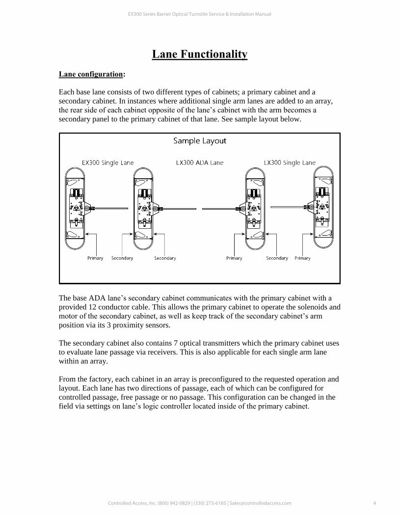
Each base lane consists of two different types of cabinets; a primary cabinet and a
secondary cabinet. In instances where additional single arm lanes are added to an array,
the rear side of each cabinet opposite of the lane’s cabinet with the arm becomes a
secondary panel to the primary cabinet of that lane. See sample layout below.
The base ADA lane’s secondary cabinet communicates with the primary cabinet with a
provided 12 conductor cable. This allows the primary cabinet to operate the solenoids and
motor of the secondary cabinet, as well as keep track of the secondary cabinet’s arm
position via its 3 proximity sensors.
The secondary cabinet also contains 7 optical transmitters which the primary cabinet uses
to evaluate lane passage via receivers. This is also applicable for each single arm lane
within an array.
From the factory, each cabinet in an array is preconfigured to the requested operation and
layout. Each lane has two directions of passage, each of which can be configured for
controlled passage, free passage or no passage. This configuration can be changed in the
field via settings on lane’s logic controller located inside of the primary cabinet.
EX300 Series Barrier Optical Turnstile Service & Installation Manual
Controlled Access, Inc. (800) 942-0829 | (330) 273-6185 | [email protected]
4
Lane Functionality (cont.)Electrical requirements:
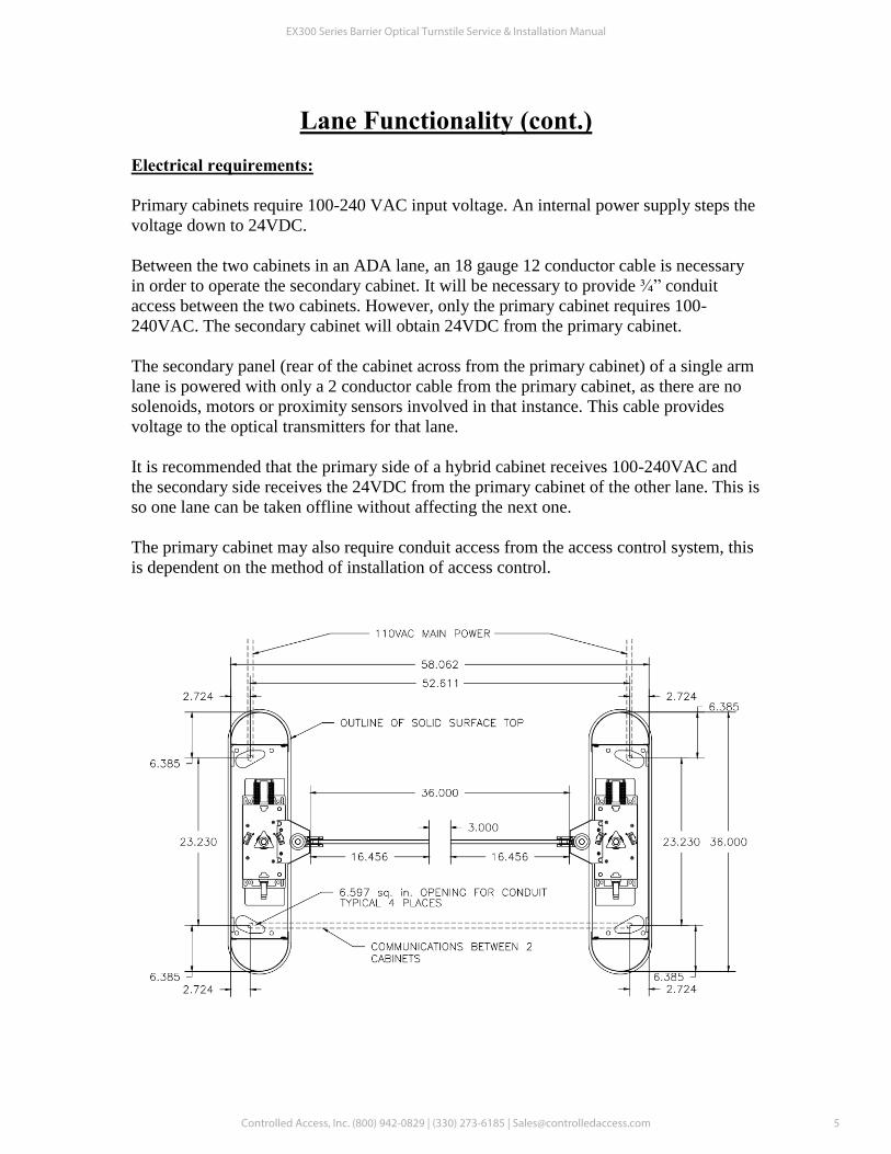
Primary cabinets require 100-240 VAC input voltage. An internal power supply steps the
voltage down to 24VDC.
Between the two cabinets in an ADA lane, an 18 gauge 12 conductor cable is necessary
in order to operate the secondary cabinet. It will be necessary to provide ¾” conduit
access between the two cabinets. However, only the primary cabinet requires 100-
240VAC. The secondary cabinet will obtain 24VDC from the primary cabinet.
The secondary panel (rear of the cabinet across from the primary cabinet) of a single arm
lane is powered with only a 2 conductor cable from the primary cabinet, as there are no
solenoids, motors or proximity sensors involved in that instance. This cable provides
voltage to the optical transmitters for that lane.
It is recommended that the primary side of a hybrid cabinet receives 100-240VAC and
the secondary side receives the 24VDC from the primary cabinet of the other lane. This is
so one lane can be taken offline without affecting the next one.
The primary cabinet may also require conduit access from the access control system, this
is dependent on the method of installation of access control.
EX300 Series Barrier Optical Turnstile Service & Installation Manual
Controlled Access, Inc. (800) 942-0829 | (330) 273-6185 | [email protected]
5
Pre-installation Preparation In order to install an EX300 lane, each cabinet needs to be opened up. Once opened,
anchor holes for concrete mounting as well as conduit access for electrical work can be
accessed. Each cabinet has two removable front panels and a lid that need to be removed
in order to install.
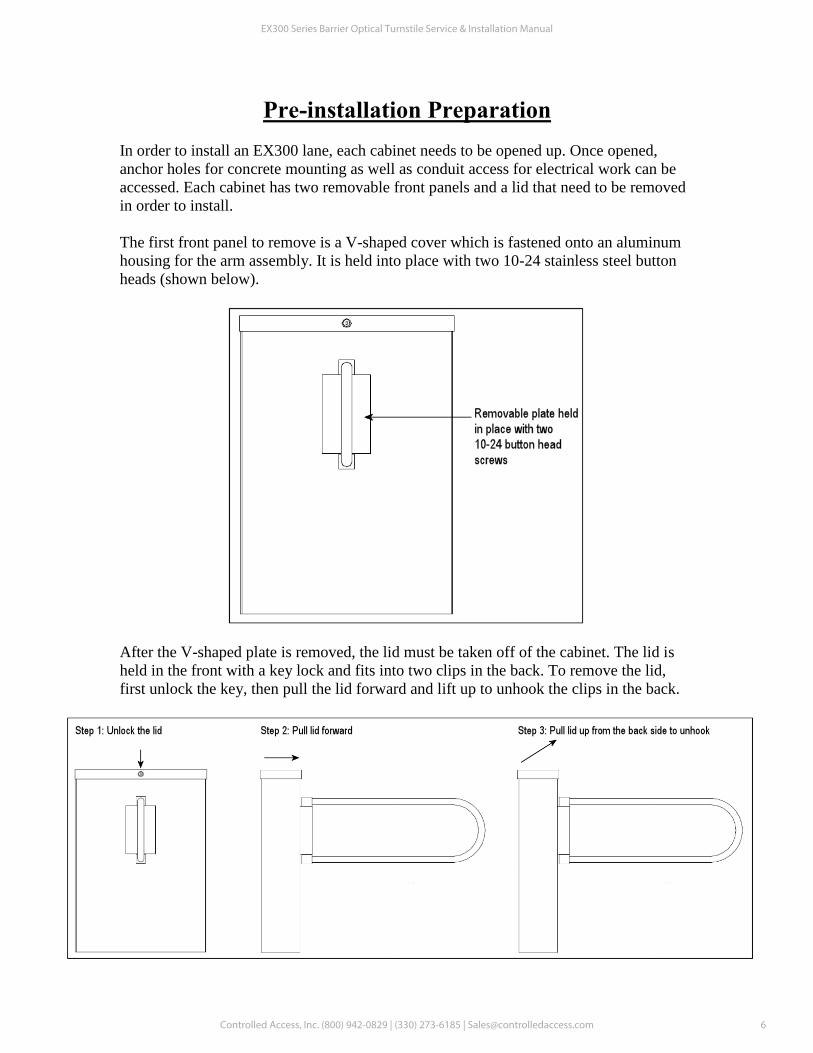
The first front panel to remove is a V-shaped cover which is fastened onto an aluminum
housing for the arm assembly. It is held into place with two 10-24 stainless steel button
heads (shown below).
After the V-shaped plate is removed, the lid must be taken off of the cabinet. The lid is
held in the front with a key lock and fits into two clips in the back. To remove the lid,
first unlock the key, then pull the lid forward and lift up to unhook the clips in the back.
EX300 Series Barrier Optical Turnstile Service & Installation Manual
Controlled Access, Inc. (800) 942-0829 | (330) 273-6185 | [email protected]
6
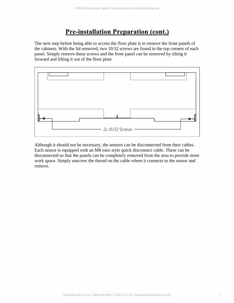
Pre-installation Preparation (cont.)The next step before being able to access the floor plate is to remove the front panels of
the cabinets. With the lid removed, two 10/32 screws are found in the top corners of each
panel. Simply remove these screws and the front panel can be removed by tilting it
forward and lifting it out of the floor plate
Although it should not be necessary, the sensors can be disconnected from their cables.
Each sensor is equipped with an M8 euro style quick disconnect cable. These can be
disconnected so that the panels can be completely removed from the area to provide more
work space. Simply unscrew the thread on the cable where it connects to the sensor and
remove.
EX300 Series Barrier Optical Turnstile Service & Installation Manual
Controlled Access, Inc. (800) 942-0829 | (330) 273-6185 | [email protected]
7

Pre-installation Preparation (cont.) Pre-installation Alignment:
Before anchoring the cabinets to the floor, we recommend laying out the lane and testing
alignment.
Place the cabinets in their approximate end location and connect the 2 conductor cable
inside of the primary cabinet to the end in the secondary cabinet. Plug in the primary
cabinet to AC voltage to power up the lane.
Inside of the primary cabinet, there is a series of 7 total photo cell sensors. Each of these
sensors is equipped with two LED’s on the rear. One of them is green and should always
be lit. The other should be solid orange while the beam is uncrossed and off while the
beam is crossed.
If the orange LED is blinking in any case, you will need to adjust the sensor alignment,
shift the cabinets so that they are straight to each other, or shim the cabinets so that they
are level.
See the sensor alignment section of this manual for advice on how to ensure the
transmitter’s light reaches the receiver properly.
EX300 Series Barrier Optical Turnstile Service & Installation Manual
Controlled Access, Inc. (800) 942-0829 | (330) 273-6185 | [email protected]
8

Use in concrete ONLY. Not recommended for use in lightweight masonry such as block or brick.
Warning!
Always wear safety glasses and other necessary protective devices or apparel when installing or working with anchors.
Caution: Use of core drills is not recommended to drill holes for use with this anchor.
Do not use an impact wrench to set or tighten the anchor. Not recommended for use in concrete which has not had su�cient time to cure.
The use of carbide drill bits manufactured with ANSI B212.15 drill bit diameter requirements is recommended for installation of this anchor.Anchor spacing and edge distance (anchor installation locations) are the responsibility of the engineer of record.
Installing product in oversized holes is not recommended. Product will not set properly or achieve full designed load in oversized holes.
* Setting torque only applies at the time of installation.
4
Select a carbide drill bit with a diameter equal to the anchor diameter. Drill hole at least 1/4” deeper than nominal anchor embedment.
Clean hole with pressurized air or vacuum to remove any excess dust/debris.
Using the washer and nut provided, assemble the anchor, leaving nut one half turn from the end of anchor to protect threads. Drive anchor through �xture to be fastened until washer is �ush to the surface of �xture.
Expand anchor by tightening nut to the speci�ed setting torque - see Table (approx 3 to 5 full revolutions).
Wedge Type Concrete Anchor Instructions
EX300 Series Barrier Optical Turnstile Service & Installation Manual
Controlled Access, Inc. (800) 942-0829 | (330) 273-6185 | [email protected] 9

Installation Instructions1. Floor should be level +/- 1/16”. If not, each cabinet must be shimmed.
Note: Anchoring optical lanes to an uneven ground most likely will cause serious
issues in unit operation.
2. Install conduit for 100-240 VAC to primary cabinet, conduit for access control
integration (if applicable), and a 3/4" conduit in between the primary and secondary
cabinet for cabling to the secondary cabinet.
3. With each cabinet in the exact position to be mounted, use a center
punch to mark location of the four holes to be drilled in the floor.
Note: Make sure each cabinet is square to each other, otherwise operation will be
inconsistent
3. If necessary, move cabinets out of the way. Drill four 3/8” holes 4” deep per
cabinet and remove all concrete dust from the holes.
4. Place cabinet in the correct location and install SS wedge type anchors
supplied. Torque the nuts to a minimum of 50 foot pounds.
5. Plug the power supply in the main cabinet into 100-240 VAC (single phase) minimum
3 amp GFI circuit.
6. The sensors we use are a thru-beam type: they require a transmitter and
receiver in order to operate. In order to accomplish this, you must connect
24VDC power to the secondary cabinet. This is accomplished with a provided 12
conductor (or 2 conductor for single lane add-on) cable. See the wiring diagram for
more information.
7. Connect access control as required to direction inputs on the logic controller.
See wiring diagram for more information.
EX300 Series Barrier Optical Turnstile Service & Installation Manual
Controlled Access, Inc. (800) 942-0829 | (330) 273-6185 | [email protected]
10
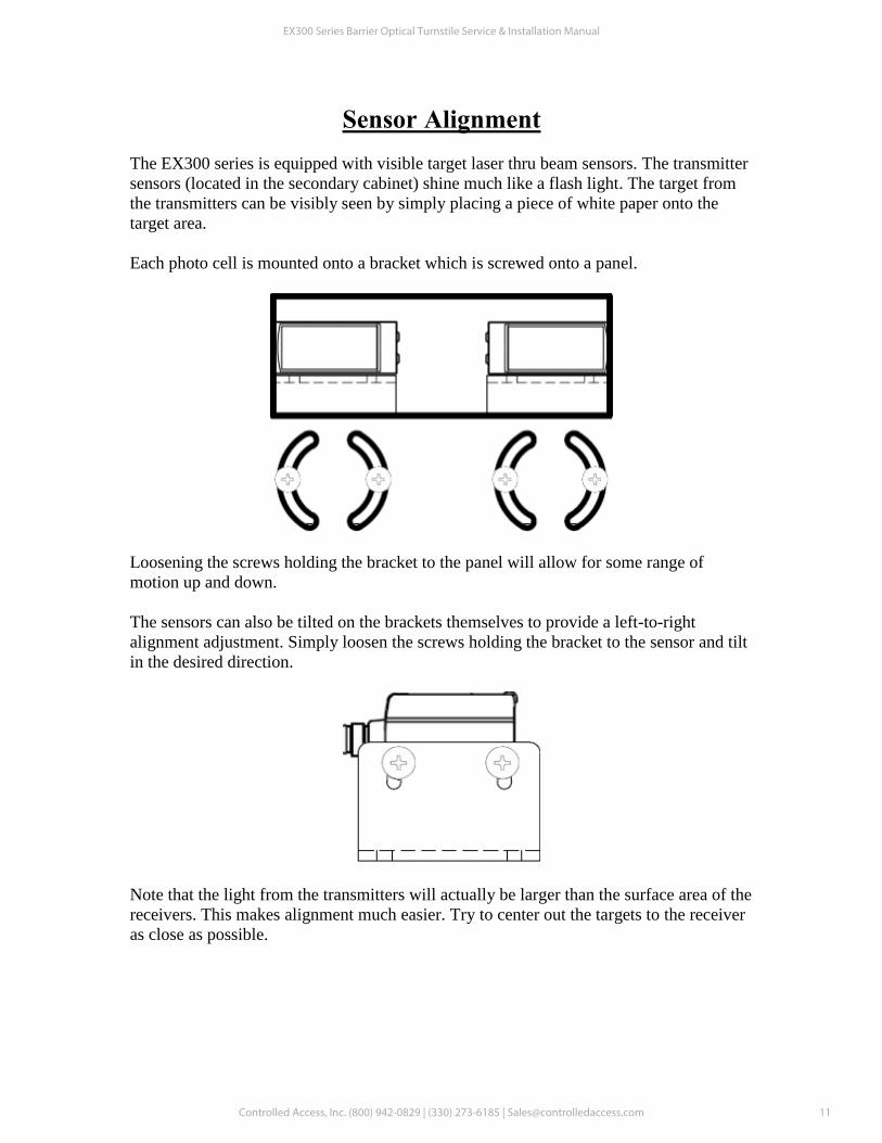
Sensor Alignment The EX300 series is equipped with visible target laser thru beam sensors. The transmitter
sensors (located in the secondary cabinet) shine much like a flash light. The target from
the transmitters can be visibly seen by simply placing a piece of white paper onto the
target area.
Each photo cell is mounted onto a bracket which is screwed onto a panel.
Loosening the screws holding the bracket to the panel will allow for some range of
motion up and down.
The sensors can also be tilted on the brackets themselves to provide a left-to-right
alignment adjustment. Simply loosen the screws holding the bracket to the sensor and tilt
in the desired direction.
Note that the light from the transmitters will actually be larger than the surface area of the
receivers. This makes alignment much easier. Try to center out the targets to the receiver
as close as possible.
EX300 Series Barrier Optical Turnstile Service & Installation Manual
Controlled Access, Inc. (800) 942-0829 | (330) 273-6185 | [email protected]
11
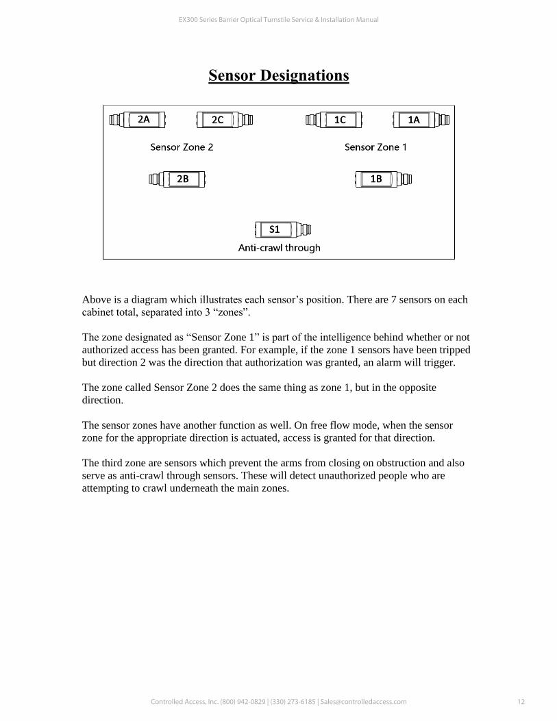
Sensor Designations
Above is a diagram which illustrates each sensor’s position. There are 7 sensors on each
cabinet total, separated into 3 “zones”.
The zone designated as “Sensor Zone 1” is part of the intelligence behind whether or not
authorized access has been granted. For example, if the zone 1 sensors have been tripped
but direction 2 was the direction that authorization was granted, an alarm will trigger.
The zone called Sensor Zone 2 does the same thing as zone 1, but in the opposite
direction.
The sensor zones have another function as well. On free flow mode, when the sensor
zone for the appropriate direction is actuated, access is granted for that direction.
The third zone are sensors which prevent the arms from closing on obstruction and also
serve as anti-crawl through sensors. These will detect unauthorized people who are
attempting to crawl underneath the main zones.
EX300 Series Barrier Optical Turnstile Service & Installation Manual
Controlled Access, Inc. (800) 942-0829 | (330) 273-6185 | [email protected]
12

EX300 Wiring IntroductionWhile very elaborate on the back end, the EX300 installation wiring is actually pretty simple.Most of the wiring is performed in the factory. In an e�ort to keep the diagrams more readable,several diagrams covering multiple aspects of the product are provided just in case.
However, during installation, the only wiring to be done is for access control, main voltageand interconnection from the primary side of a lane to the secondary. In terms of access control,a contact closure between 24VDC + and the desired input is needed from a relay (therecould be as many as six relay inputs needed depending on how the product is intended tobe used.
Interconnection is achieved with a 12 conductor cable (for ADA lanes) or a 2 conductor cable(for a single arm lane). In the factory, we terminate both ends of this cable during assembly,then snip o� a short length on the secondary side for easy wire color matching. Some wiresmay not be used and can be used for other purposes such as adding devices to the unit.
Refer to the following diagrams provided for reference, but keep in mind that most of theseterminations are already made for you.
The next page will act as a wiring legend to illustrate what each terminal on the PLC does. This diagram is followed by actual wiring schematics.
The �rst schematic labeled “Access Control and Indication” shows where all the access controlterminations are supposed to land while the second diagram labeled “ADA Lane Secondary Cabinet Wiring Diagram” which shows the terminals to connect the interconnection cable to.
All other wiring diagrams provided are for troubleshooting and reference only.
EX300 Series Barrier Optical Turnstile Service & Installation Manual
Controlled Access, Inc. (800) 942-0829 | (330) 273-6185 | [email protected]
13

EX300 Wiring Legend
C1 O1 O2 C2 O3 C3 O4 O5 C4 O6 O7 C5 O8O8\ C1 O1 O2 C2 O3 C2 O3C3 O4 C3 O4C1 O1 O2
+ - I1 I2 I3 I4 I5 I6 I7 I8 I9 IA IB IC ID IE IF IG I1 I2 I3 I4 I5 I6 I1 I2 I3 I4 I5 I6
Main PLC Outputs
Expansion 1 Outputs Expansion 2 Outputs
C1 - Connect to 24VDC+O1- Dir 1 Yellow LEDO2- Dir 1 Green LEDC2 - Connect to 24VDC +O3 - Dir 1 Red LEDC3 - Connect to 24VDC +O4 - Dir 2 Yellow LEDO5 - Dir 2 Green LEDC4 - Connect to 24VDC +O6 - Dir 2 Red LEDO7 - Alarm (Solid State)C5 - Connect to 24VDC +O8 - Alarm (Pulsing)O8/ - Not Used
C1 - Connect to 24VDC+O1- Arm 1 Dir 1 SolenoidO2- Arm 1 Dir 2 SolenoidC2 - Connect to 24VDC +O3 - Arm 2 Dir 1 SolenoidC3 - Arm 2 Dir 2 SolenoidO4 - Dir 2 Yellow LED
C1 - Connect to 24VDC+O1- Arm 1 Motor CWO2- Arm 1 Motor CCWC2 - Connect to 24VDC +O3 - Arm 2 Motor CWC3 - Arm 2 Motor CCWO4 - Dir 2 Yellow LED
Main PLC Inputs+ - Input 24VDC +- - Input 224VDC -I1 - Direction 1 InputI2 - Direction 2 InputI3 - Direction 1 OverrideI4 - Direction 2 OverrideI5 - Sensor 1A I6 - Sensor 1BI7 - Sensor 1CI8 - Sensor S1I9 - Sensor 2CIA - Sensor 2BIB - Sensor 2AIC - Arm 1 Dir 1 ProxID - Arm 1 Home ProxIE - Arm 1 Dir 2 ProxIF - Arm 2 Dir 1 ProxIG - Arm 2 Home Prox
I1 - Arm 2 Dir 2 ProxI2 - Direction 1 ApproachI3 - Direction 2 ApproachI4 - Direction 1 Mode ChangeI5 - Direction 2 Mode ChangeI6 - Not Used
I1 - Not UsedI2 - Not UsedI3 - Not UsedI4 - Not UsedI5 - Not UsedI6 - Not Used
Expansion 1 Inputs Expansion 2 Inputs
All inputs are PNP type transistor inputs - apply local 24VDC + to terminal for PLC to register.
Installations may use as few as one contact closure and as many as six depending on the complexity of the application.
To activate multiple lanes at the same time, each lane must source it’s input from the same power supplyit comes from. Add ice cube relays to trigger multiple lanes together to ensure the power for the inputis coming from the same power supply the PLC is.
All outputs are relay outputs. Many of these share commons. These commons are all tied to 24VDC+.
You may piggyback onto one of the common terminals to get 24VDC to operate other devices.
Other notes: Direction 1 is with the primary cabinet on your left, Direction 2 is the primary cabinet on the right.
Single arm lanes will not use as many terminals. Anything relayed to Arm 2 will be missing in this instance.
EX300 Series Barrier Optical Turnstile Service & Installation Manual
Controlled Access, Inc. (800) 942-0829 | (330) 273-6185 | [email protected]
14
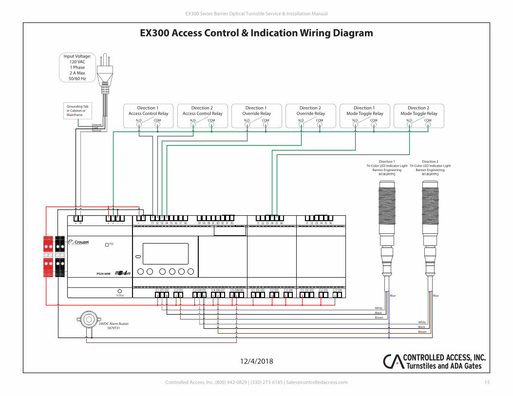
EX300 Access Control & Indication Wiring Diagram
Input Voltage:120 VAC1 Phase2 A Max50/60 Hz
Grounding Tabin Cabinet orMainframe
NeutralLoadGround
C1 O1 O2 C2 O3 C3 O4 O5 C4 O6 O7 C5 O8O8\ C1 O1 O2 C2 O3 C2 O3C3 O4 C3 O4C1 O1 O2
+ - I1 I2 I3 I4 I5 I6 I7 I8 I9 IA IB IC ID IE IF IG I1 I2 I3 I4 I5 I6 I1 I2 I3 I4 I5 I6L N
V Out
PS24-60W
-+ + -
Direction 1Tri-Color LED Indicator Light
Banner EngineeringM18GRYPQ
Direction 2Tri-Color LED Indicator Light
Banner EngineeringM18GRYPQ
Blue Blue
White
Black
Brown
Direction 1 Access Control Relay
N.O. COM
Direction 2 Access Control Relay
N.O. COM
Direction 1 Override Relay
N.O. COM
Direction 2 Override Relay
N.O. COM
Direction 2 Mode Toggle Relay
N.O. COM
Direction 1 Mode Toggle Relay
N.O. COM
24VDC Alarm Buzzer5670T31
White
Black
Brown
12/4/2018
EX300 Series Barrier Optical Turnstile Service & Installation Manual
Controlled Access, Inc. (800) 942-0829 | (330) 273-6185 | [email protected] 15
Pin 1 - Black/WhitePin 2 - Red/BlackPin 3 - Jumper from Pin 10
Pin 5 - WhitePin 4 - Blue
Pin 6 - Orange/BlackPin 7 - Blue/BlackPin 8 - Green/BlackPin 9 - RedPin 10 - Black & Jumper to Pin 3Pin 11 - White/Black & OrangePin 12 - Green
Direction 1Solenoid
DeltrolD4A 53717-82
Direction 2Solenoid
DeltrolD4A 53717-82
Bodine24A-2 Series
DC Gear MotorModel 0162
Direction 1 Max TravelSICK Proximity Sensor
1040763
Direction 2 Max TravelSICK Proximity Sensor
1040763
Hom
e Po
sitio
nSI
CK P
roxi
mity
Sen
sor
1040
763
Motor Black (-)Motor White (+)
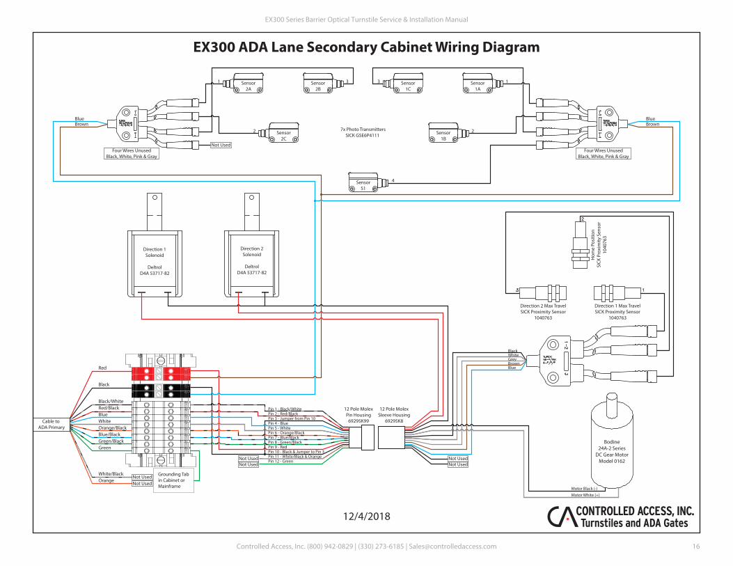
EX300 ADA Lane Secondary Cabinet Wiring Diagram
Sensor2B
Sensor2C
Sensor1C
Sensor1B
Sensor2A
Sensor1A
SensorS1
Not Used
1
2
3
4
31
2
Red
Black
Black/WhiteRed/BlackBlueWhiteOrange/BlackBlue/BlackGreen/BlackGreen
White/BlackOrange
Cable to ADA Primary
Not UsedNot Used
BlueBrown
BlueBrown
Four Wires UnusedBlack, White, Pink & Gray
Four Wires UnusedBlack, White, Pink & Gray
Grounding Tabin Cabinet orMainframe
7x Photo TransmittersSICK GSE6P4111
BrownBlue
Black
GreyWhite
Not UsedNot Used
Not UsedNot Used
12 Pole MolexSleeve Housing
69295K8
12 Pole MolexPin Housing
69295K99
12/4/2018
EX300 Series Barrier Optical Turnstile Service & Installation Manual
Controlled Access, Inc. (800) 942-0829 | (330) 273-6185 | [email protected] 16
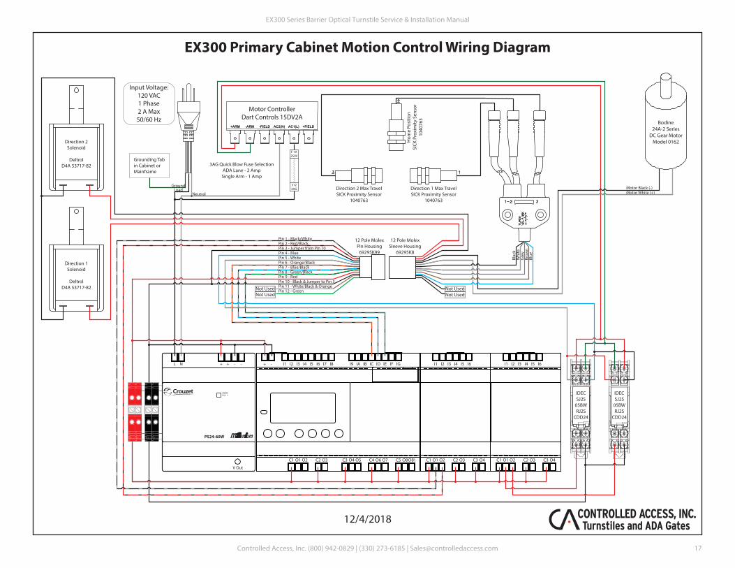
EX300 Primary Cabinet Motion Control Wiring Diagram
+FIELDAC1(L)AC2(N)-FIELD-ARM+ARM
F 1A250V
3123AG
Direction 1Solenoid
DeltrolD4A 53717-82
Direction 2Solenoid
DeltrolD4A 53717-82
Input Voltage:120 VAC1 Phase2 A Max50/60 Hz
Grounding Tabin Cabinet orMainframe
NeutralLoad
Ground
Motor ControllerDart Controls 15DV2A
Bodine24A-2 Series
DC Gear MotorModel 0162
Direction 1 Max TravelSICK Proximity Sensor
1040763
Direction 2 Max TravelSICK Proximity Sensor
1040763
Hom
e Po
sitio
nSI
CK P
roxi
mity
Sen
sor
1040
763
Motor White (+)Motor Black (-)
5
6 3
4
2
18
7
5
6 3
4
2
18
7
IDECSJ2S
05BWRJ2S
CDD24
IDECSJ2S
05BWRJ2S
CDD24
3AG Quick Blow Fuse SelectionADA Lane - 2 Amp
Single Arm - 1 Amp
C1 O1 O2 C2 O3 C3 O4 O5 C4 O6 O7 C5 O8O8\ C1 O1 O2 C2 O3 C2 O3C3 O4 C3 O4C1 O1 O2
+ - I1 I2 I3 I4 I5 I6 I7 I8 I9 IA IB IC ID IE IF IG I1 I2 I3 I4 I5 I6 I1 I2 I3 I4 I5 I6L N
V Out
PS24-60W
-+ + -
Brow
nBl
ue
Blac
k
Gre
yW
hite
Pin 1 - Black/WhitePin 2 - Red/BlackPin 3 - Jumper from Pin 10
Pin 5 - WhitePin 4 - Blue
Pin 6 - Orange/BlackPin 7 - Blue/BlackPin 8 - Green/BlackPin 9 - RedPin 10 - Black & Jumper to Pin 3Pin 11 - White/Black & OrangePin 12 - Green Not Used
Not UsedNot UsedNot Used
12 Pole MolexSleeve Housing
69295K8
12 Pole MolexPin Housing
69295K99
12/4/2018
EX300 Series Barrier Optical Turnstile Service & Installation Manual
Controlled Access, Inc. (800) 942-0829 | (330) 273-6185 | [email protected]
17
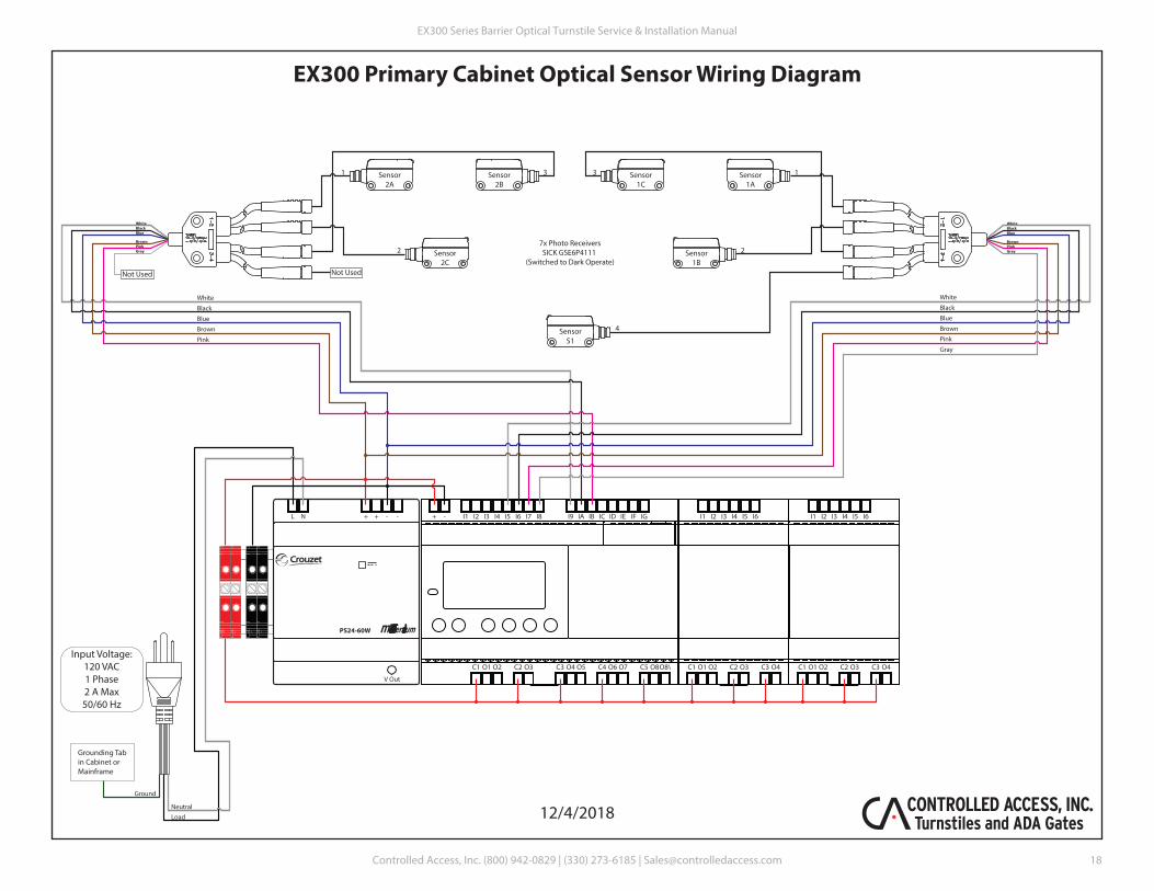
EX300 Primary Cabinet Optical Sensor Wiring Diagram
C1 O1 O2 C2 O3 C3 O4 O5 C4 O6 O7 C5 O8O8\ C1 O1 O2 C2 O3 C2 O3C3 O4 C3 O4C1 O1 O2
+ - I1 I2 I3 I4 I5 I6 I7 I8 I9 IA IB IC ID IE IF IG I1 I2 I3 I4 I5 I6 I1 I2 I3 I4 I5 I6L N
V Out
PS24-60W
-+ + -
Input Voltage:120 VAC1 Phase2 A Max50/60 Hz
Grounding Tabin Cabinet orMainframe
Neutral
Load
Ground
Sensor2B
Sensor2C
Sensor1C
Sensor1B
Sensor2A
Sensor1A
SensorS1
WhiteBlackBlue
BrownPinkGray
WhiteBlackBlue
BrownPinkGray
White
Black
Blue
Brown
Pink
Gray
White
Black
Blue
Brown
Pink
Not UsedNot Used
1
2
3
4
31
27x Photo ReceiversSICK GSE6P4111
(Switched to Dark Operate)
12/4/2018
EX300 Series Barrier Optical Turnstile Service & Installation Manual
Controlled Access, Inc. (800) 942-0829 | (330) 273-6185 | [email protected]
18
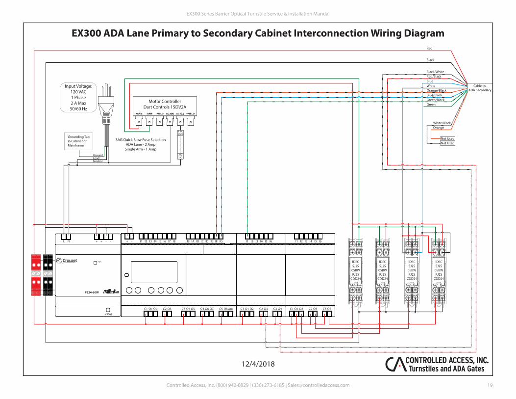
EX300 ADA Lane Primary to Secondary Cabinet Interconnection Wiring Diagram
+FIELDAC1(L)AC2(N)-FIELD-ARM+ARM
F 1A250V
3123AG
Input Voltage:120 VAC1 Phase2 A Max50/60 Hz
Grounding Tabin Cabinet orMainframe
NeutralLoadGround
Motor ControllerDart Controls 15DV2A
5
6 3
4
2
18
7
5
6 3
4
2
18
7
IDECSJ2S
05BWRJ2S
CDD24
IDECSJ2S
05BWRJ2S
CDD24
3AG Quick Blow Fuse SelectionADA Lane - 2 Amp
Single Arm - 1 Amp
C1 O1 O2 C2 O3 C3 O4 O5 C4 O6 O7 C5 O8O8\ C1 O1 O2 C2 O3 C2 O3C3 O4 C3 O4C1 O1 O2
+ - I1 I2 I3 I4 I5 I6 I7 I8 I9 IA IB IC ID IE IF IG I1 I2 I3 I4 I5 I6 I1 I2 I3 I4 I5 I6L N
V Out
PS24-60W
-+ + -
Red
Black
Blue
Green
White/BlackOrange
Cable to ADA Secondary
5
6 3
4
2
18
7
5
6 3
4
2
18
7
IDECSJ2S
05BWRJ2S
CDD24
IDECSJ2S
05BWRJ2S
CDD24
Black/WhiteRed/BlackBlueWhiteOrange/BlackBlue/BlackGreen/Black
Not UsedNot Used
12/4/2018
EX300 Series Barrier Optical Turnstile Service & Installation Manual
Controlled Access, Inc. (800) 942-0829 | (330) 273-6185 | [email protected]
19
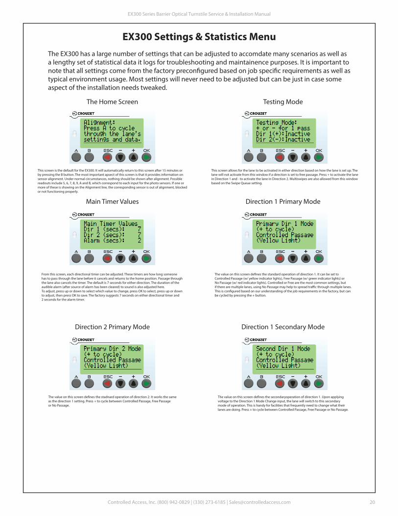
EX300 Settings & Statistics MenuThe EX300 has a large number of settings that can be adjusted to accomdate many scenarios as well asa lengthy set of statistical data it logs for troubleshooting and maintainence purposes. It is important tonote that all settings come from the factory precon�gured based on job speci�c requirements as well astypical environment usage. Most settings will never need to be adjusted but can be just in case some aspect of the installation needs tweaked.
The Home Screen
This screen is the default for the EX300. It will automatically return to this screen after 15 minutes or by pressing the B button. The most important apsect of this screen is that it provides information onsensor alignment. Under normal circumstances, nothing should be shown after alignment. Possiblereadouts include 5, 6, 7, 8, 9, A and B, which correspond to each input for the photo sensors. If one ormore of these is showing on the Alignment line, the corresponding sensor is out of alignment, blockedor not functioning properly.
Testing Mode
This screen allows for the lane to be activated in either direction based on how the lane is set up. Thelane will not activate from this window if a direction is set to free passage. Press + to activate the lanein Direction 1 and - to activate the lane in Direction 2. Multiswipes are also allowed from this windowbased on the Swipe Queue setting.
Main Timer Values
From this screen, each directional timer can be adjusted. These timers are how long someonehas to pass through the lane before it cancels and returns to the home position. Passage throughthe lane also cancels the timer. The default is 7 seconds for either direction. The duration of theaudible alarm (after source of alarm has been cleared) to sound is also adjusted here.To adjust, press up or down to select which value to change, press OK to select, press up or down to adjust, then press OK to save. The factory suggests 7 seconds on either directional timer and2 seconds for the alarm timer.
Direction 1 Primary Mode
The value on this screen de�nes the standard operation of direction 1. It can be set toControlled Passage (w/ yellow indicator lights), Free Passage (w/ green indicator lights) orNo Passage (w/ red indicator lights). Controlled or Free are the most common settings, butif there are multiple lanes, using No Passage may help to spread tra�c through multiple lanes.This is con�gured based on our understanding of the job requirements in the factory, but canbe cycled by pressing the + button.
Direction 2 Primary Mode
The value on this screen de�nes the stadnard operation of direction 2. It works the sameas the direction 1 setting. Press + to cycle between Controlled Passage, Free Passageor No Passage.
Direction 1 Secondary Mode
The value on this screen de�nes the secondaryoperation of direction 1. Upon applyingvoltage to the Direction 1 Mode Change input, the lane will switch to this secondarymode of operation. This is handy for facilities that frequently need to change what theirlanes are doing. Press + to cycle between Controlled Passage, Free Passage or No Passage.
EX300 Series Barrier Optical Turnstile Service & Installation Manual
Controlled Access, Inc. (800) 942-0829 | (330) 273-6185 | [email protected]
20
EX300 Settings & Statistics, continued
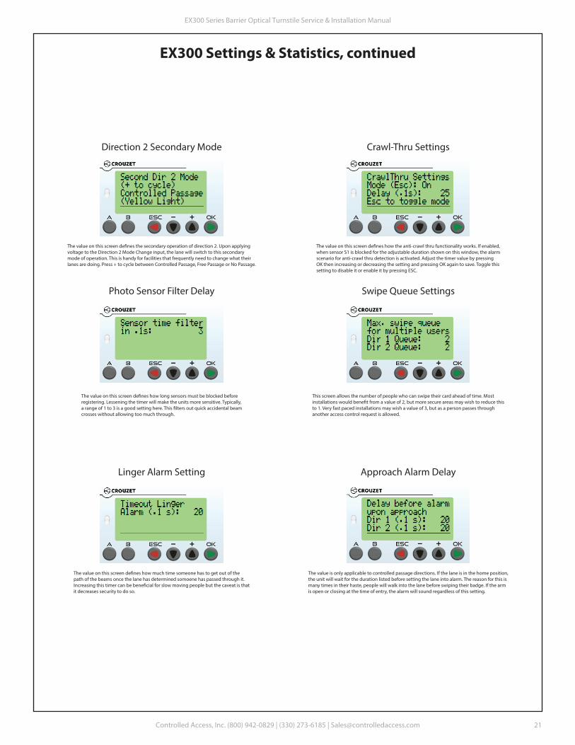
Direction 2 Secondary Mode
The value on this screen de�nes the secondary operation of direction 2. Upon applyingvoltage to the Direction 2 Mode Change input, the lane will switch to this secondarymode of operation. This is handy for facilities that frequently need to change what theirlanes are doing. Press + to cycle between Controlled Passage, Free Passage or No Passage.
Crawl-Thru Settings
The value on this screen de�nes how the anti-crawl thru functionality works. If enabled,when sensor S1 is blocked for the adjustable duration shown on this window, the alarmscenario for anti-crawl thru detection is activated. Adjust the timer value by pressingOK then increasing or decreasing the setting and pressing OK again to save. Toggle thissetting to disable it or enable it by pressing ESC.
Photo Sensor Filter Delay
The value on this screen de�nes how long sensors must be blocked beforeregistering. Lessening the timer will make the units more sensitive. Typically,a range of 1 to 3 is a good setting here. This �lters out quick accidental beamcrosses without allowing too much through.
Swipe Queue Settings
This screen allows the number of people who can swipe their card ahead of time. Mostinstallations would bene�t from a value of 2, but more secure areas may wish to reduce thisto 1. Very fast paced installations may wish a value of 3, but as a person passes through another access control request is allowed.
Linger Alarm Setting
The value on this screen de�nes how much time someone has to get out of the path of the beams once the lane has determined somoene has passed through it.Increasing this timer can be bene�cial for slow moving people but the caveat is thatit decreases security to do so.
Approach Alarm Delay
The value is only applicable to controlled passage directions. If the lane is in the home position,the unit will wait for the duration listed before setting the lane into alarm. The reason for this ismany times in their haste, people will walk into the lane before swiping their badge. If the armis open or closing at the time of entry, the alarm will sound regardless of this setting.
EX300 Series Barrier Optical Turnstile Service & Installation Manual
Controlled Access, Inc. (800) 942-0829 | (330) 273-6185 | [email protected]
21
EX300 Settings & Statistics, continued
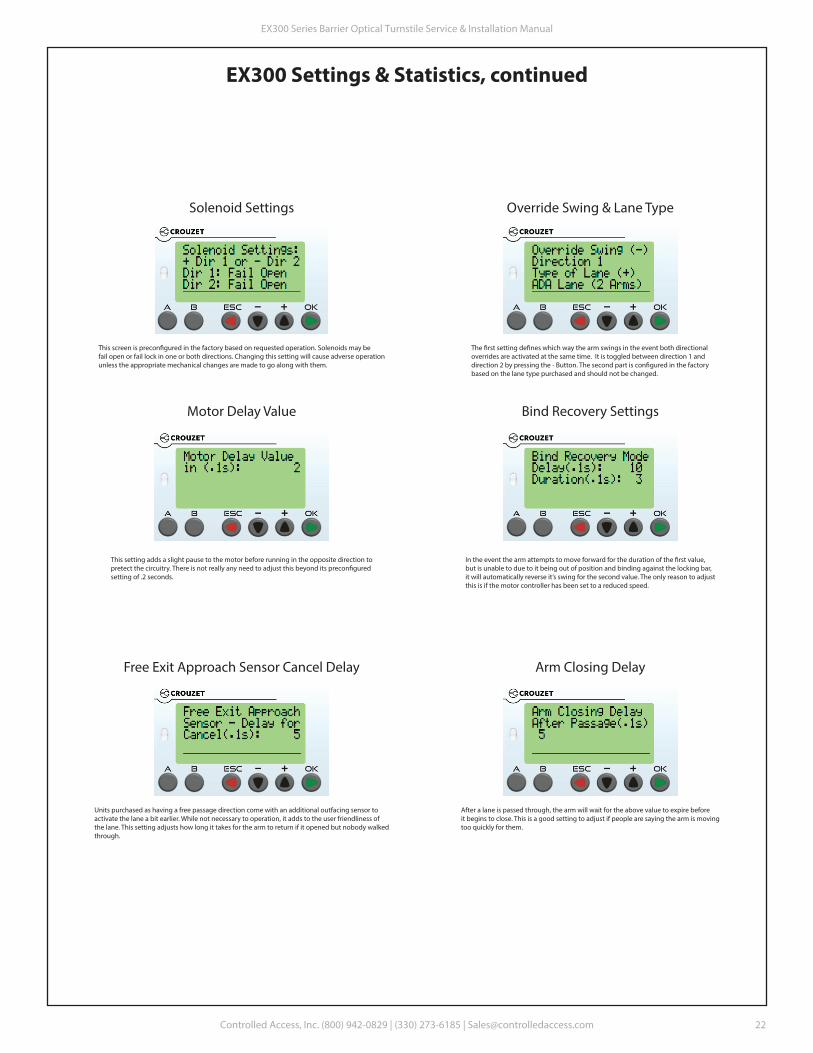
Solenoid Settings
This screen is precon�gured in the factory based on requested operation. Solenoids may befail open or fail lock in one or both directions. Changing this setting will cause adverse operationunless the appropriate mechanical changes are made to go along with them.
Override Swing & Lane Type
The �rst setting de�nes which way the arm swings in the event both directional overrides are activated at the same time. It is toggled between direction 1 anddirection 2 by pressing the - Button. The second part is con�gured in the factorybased on the lane type purchased and should not be changed.
This setting adds a slight pause to the motor before running in the opposite direction topretect the circuitry. There is not really any need to adjust this beyond its precon�guredsetting of .2 seconds.
Motor Delay Value Bind Recovery Settings
In the event the arm attempts to move forward for the duration of the �rst value, but is unable to due to it being out of position and binding against the locking bar, it will automatically reverse it’s swing for the second value. The only reason to adjustthis is if the motor controller has been set to a reduced speed.
Units purchased as having a free passage direction come with an additional outfacing sensor toactivate the lane a bit earlier. While not necessary to operation, it adds to the user friendliness of the lane. This setting adjusts how long it takes for the arm to return if it opened but nobody walkedthrough.
Free Exit Approach Sensor Cancel Delay Arm Closing Delay
After a lane is passed through, the arm will wait for the above value to expire beforeit begins to close. This is a good setting to adjust if people are saying the arm is movingtoo quickly for them.
EX300 Series Barrier Optical Turnstile Service & Installation Manual
Controlled Access, Inc. (800) 942-0829 | (330) 273-6185 | [email protected]
22
EX300 Settings & Statistics, continued
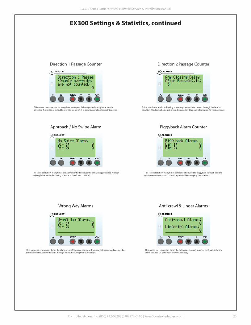
This screen has a readout showing how many people have passed through the lane indirection 1 (outside of a double override scenario). It is good information for maintainence.
Direction 1 Passage Counter Direction 2 Passage Counter
This screen has a readout showing how many people have passed through the lane indirection 2 (outside of a double override scenario). It is good information for maintainence.
This screen lists how many times the alarm went o� because the arm was approached withoutswiping (whether while closing or while in the closed position).
Approach / No Swipe Alarm Piggyback Alarm Counter
This screen lists how many times someone attempted to piggyback through the laneon someone elses access control request without swiping themselves.
This screen lists how many times the alarm went o� because someone from one side requested passage butsomeone on the other side went through without swiping their own badge.
Wrong Way Alarms Anti-crawl & Linger Alarms
This screen lists how many times the anti-crawl through alarm or the linger in beamalarm occured (as de�ned in previous settings).
EX300 Series Barrier Optical Turnstile Service & Installation Manual
Controlled Access, Inc. (800) 942-0829 | (330) 273-6185 | [email protected]
23
EX300 Settings & Statistics, continued
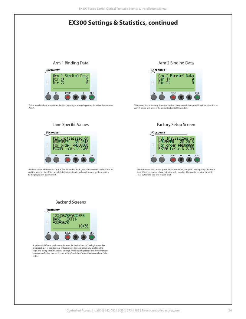
This screen lists how many times the bind recovery scenario happened for either direction onArm 1.
Arm 1 Binding Data Arm 2 Binding Data
This screen lists how many times the bind recovery scenario happened for either direction onArm 2. Single arm lanes will automatically skip this window.
This lane shows when the PLC was activated for the project, the order number the lane was forand the logic version. This is very helpful information to technical support so the speci�csto the project can be reviewed.
Lane Speci�c Values
This window should never appear unless something happens to completely restart thelogic. If this occurs somehow, enter the order number if known by pressing the A, B, - & + buttons to add one to each digit.
Factory Setup Screen
A variety of di�erent readouts and menus for the backend of the logic controllerare available. It is best to avoid tinkering here to avoid accidently resetting the logic and losing all of the project settings. Avoid holding escape and if this managesto enter any further menus, try not to “stop” and then “reset all values and start” thelogic.
Backend Screens
EX300 Series Barrier Optical Turnstile Service & Installation Manual
Controlled Access, Inc. (800) 942-0829 | (330) 273-6185 | [email protected]
24

Warranty Information
Seller warrants the goods against defective workmanship and materials provided that Buyer notify Sellerwithin one (1) year after receipt by Buyer of the goods of any claim under this Warranty. The liability ofSeller shall be limited to replacing or repairing defective goods returned by Buyer and delivered to thefactory of the Seller, transportation charges prepaid.
Replaced or repaired goods will be redelivered freight prepaid to the address of Buyer shown hereon.Except for the Warranty contained herein, there shall be no other warranties, such as warranties of �tnessand merchantability or otherwise express or implied, written or verbal, and Seller shall not be liable forconsequential damages in any event.
EX300 Series Barrier Optical Turnstile Service & Installation Manual
Controlled Access, Inc. (800) 942-0829 | (330) 273-6185 | [email protected]
25
Related Documents