WEIR CONTROL & CHOKE VALVES Excellent solutions providing optimum performance for all Turbine Bypass applications Excellent Power & Industrial Solutions Excellent Engineering Solutions Weir Turbine Bypass Valves & Desuperheaters

Welcome message from author
This document is posted to help you gain knowledge. Please leave a comment to let me know what you think about it! Share it to your friends and learn new things together.
Transcript
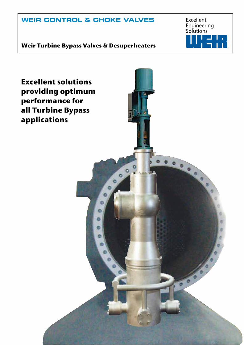
WEIR CONTROL & CHOKE VALVES
Excellent solutions providing optimum performance for all Turbine Bypass applications
ExcellentPower & IndustrialSolutions
ExcellentEngineeringSolutions
Weir Turbine Bypass Valves & Desuperheaters
Quality assuranceWeir is qualified to industry standards and working practices including:
� ASME BPVC Section III (N and NPT Stamp) � NQA-1 Quality system � 10CFR50 App. B � 10CFR50 Part 21 � RCC-E � RCC-M � CSA Z299 � Performance testing and qualification to:ASME QME-1ASME B16.41IEEE 323IEEE 344IEEE 382
� ISO 9001:2008 � ISO 14001 � PED 97/23/CE � API Q1 TO API LICENCES:
API 6D (6D-0182)API 6A (64-0445)
� OHSAS 18001 � ATEX 94/9/CE � Lean manufacturing practices
www.weirpowerindustrial.comWeir Control & Choke valves Engineered valves for protection & process control2
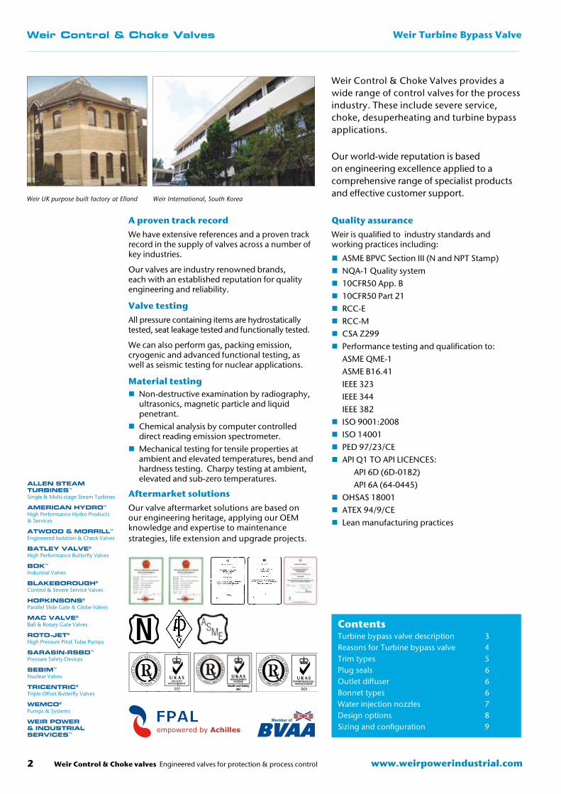
A proven track recordWe have extensive references and a proven track record in the supply of valves across a number of key industries.
Our valves are industry renowned brands, each with an established reputation for quality engineering and reliability.
Valve testingAll pressure containing items are hydrostatically tested, seat leakage tested and functionally tested.
We can also perform gas, packing emission, cryogenic and advanced functional testing, as well as seismic testing for nuclear applications.
Material testing � Non-destructive examination by radiography, ultrasonics, magnetic particle and liquid penetrant.
� Chemical analysis by computer controlled direct reading emission spectrometer.
� Mechanical testing for tensile properties at ambient and elevated temperatures, bend and hardness testing. Charpy testing at ambient, elevated and sub-zero temperatures.
Aftermarket solutionsOur valve aftermarket solutions are based on our engineering heritage, applying our OEM knowledge and expertise to maintenance strategies, life extension and upgrade projects.
Weir Control & Choke Valves provides a wide range of control valves for the process industry. These include severe service, choke, desuperheating and turbine bypass applications. Our world-wide reputation is based on engineering excellence applied to a comprehensive range of specialist products and effective customer support.
Weir UK purpose built factory at Elland
ContentsTurbine bypass valve description 3Reasons for Turbine bypass valve 4Trim types 5Plug seals 6Outlet diffuser 6Bonnet types 6Water injection nozzles 7Design options 8Sizing and configuration 9
Weir Control & Choke Valves Weir Turbine Bypass Valve
Member of
Weir International, South Korea
Weir Control & Choke valves Engineered valves for protection & process control 3www.weirpowerindustrial.com
Weir Control & Choke Valves Weir Turbine Bypass Valve
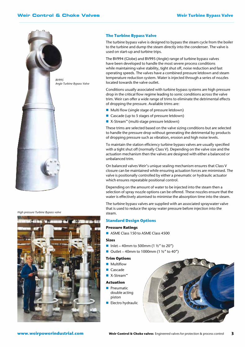
The Turbine Bypass Valve
The turbine bypass valve is designed to bypass the steam cycle from the boiler to the turbine and dump the steam directly into the condenser. The valve is used on start-up and turbine trips.
The BV994 (Globe) and BV995 (Angle) range of turbine bypass valves have been developed to handle the most severe process conditions while maintaining valve stability, tight shut off, noise reduction and fast operating speeds. The valves have a combined pressure letdown and steam temperature reduction system. Water is injected through a series of nozzles located towards the valve outlet.
Conditions usually associated with turbine bypass systems are high pressure drop in the critical flow regime leading to sonic conditions across the valve trim. Weir can offer a wide range of trims to eliminate the detrimental effects of dropping the pressure. Available trims are:
� Multi flow (single stage of pressure letdown)
� Cascade (up to 5 stages of pressure letdown)
� X-Stream™ (multi-stage pressure letdown)
These trims are selected based on the valve sizing conditions but are selected to handle the pressure drop without generating the detrimental by products of dropping pressure such as vibration, erosion and high noise levels.
To maintain the station efficiency turbine bypass valves are usually specified with a tight shut off (normally Class V). Depending on the valve size and the actuation mechanism then the valves are designed with either a balanced or unbalanced trim.
On balanced valves Weir’s unique sealing mechanism ensures that Class V closure can be maintained while ensuring actuation forces are minimised. The valve is positionally controlled by either a pneumatic or hydraulic actuator which ensures repeatable positional control.
Depending on the amount of water to be injected into the steam then a selection of spray nozzle options can be offered. These nozzles ensure that the water is effectively atomised to minimise the absorption time into the steam.
The turbine bypass valves are supplied with an associated spraywater valve that is used to reduce the spray water pressure before injection into the steam.
Standard Design Options
Pressure Ratings � ASME Class 150 to ASME Class 4500
Sizes � Inlet – 40mm to 500mm (1 ½” to 20”)
� Outlet – 40mm to 1000mm (1 ½” to 40”)
Trim Options � Multiflow
� Cascade
� X-Stream™
Actuation � Pneumatic double acting piston
� Electro hydraulic
BV995 Angle Turbine Bypass Valve
High pressure Turbine Bypass valve
www.weirpowerindustrial.comWeir Control & Choke valves Engineered valves for protection & process control4
Weir Turbine Bypass ValveWeir Control & Choke Valves
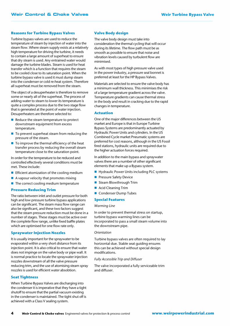
Reasons for Turbine Bypass Valves
Turbine bypass valves are used to reduce the temperature of steam by injection of water into the steam flow. Where steam supply exists at a relatively high temperature for driving the turbine, it needs to contain a large amount of superheat to ensure that dry steam is used. Any entrained water would damage the turbine blades. Steam is used for heat transfer which is a function that requires the steam to be cooled close to its saturation point. When the turbine bypass valve is used it must dump steam into the condenser or cold re-heat system. Therefore all superheat must be removed from the steam.
The object of a desuperheater is therefore to remove some or nearly all of the superheat. The process of adding water to steam to lower its temperature is quite a complex process due to the two stage flow that is generated at the point of water injection. Desuperheaters are therefore selected to:
� Reduce the steam temperature to protect downstream equipment from excess temperature.
� To prevent superheat steam from reducing the pressure of the steam.
� To improve the thermal efficiency of the heat transfer process by reducing the overall steam temperature close to the saturation point.
In order for the temperature to be reduced and controlled effectively several conditions must be met. These include:
� Efficient atomization of the cooling medium
� A vapour velocity that promotes mixing
� The correct cooling medium temperature
Pressure Reducing Trim
The ratio between inlet and outlet pressure for both high and low pressure turbine bypass applications can be significant. The steam mass flow range can also be significant, and these two factors suggest that the steam pressure reduction must be done in a number of stages. These stages must be active over the complete flow range, unlike fixed baffle plates which are optimised for one flow rate only.
Spraywater Injection Nozzles
It is usually important for the spraywater to be evaporated within a very short distance from its injection point. It is also critical to ensure that water does not impinge on the valve body or pipe wall. It is normal practice to locate the spraywater injection nozzles downstream of all the valve pressure reducing trim, and the use of atomising steam spray nozzles is used for efficient water absobtion.
Seat Tightness
When Turbine Bypass Valves are discharging into the condenser it is imperative that they have a tight shutoff to ensure that the partial vacuum existing in the condenser is maintained. The tight shut off is achieved with a Class V sealing system.
Valve Body design
The valve body design must take into consideration the thermal cycling that will occur during its lifetime. The flow path must be as smooth as possible to ensure that noise and vibration levels caused by turbulent flow are minimised.
As with most types of high pressure valve used in the power industry, a pressure seal bonnet is preferred at least for the HP Bypass Valves.
Materials are selected to ensure the valve body has a minimum wall thickness. This minimises the risk of a large temperature gradient across the valve. Temperature gradients can cause thermal stress in the body and result in cracking due to the rapid changes in temperature.
Actuation
One of the major differences between the US market and Europe is that in Europe Turbine Bypass Systems are predominantly actuated by Hydraulic Power Units and cylinders. In the US Combined Cycle market Pneumatic systems are preferred for cost reasons, although in the US Fossil fired stations, hydraulic units are required due to the higher actuation forces required.
In addition to the main bypass and spraywater valves there are a number of other significant elements that make up a Bypass system.
� Hydraulic Power Units including PLC systems
� Pressure Safety Device
� Steam Blowthrough Trim
� Acid Cleaning Trim
� Condenser Dump Tubes
Special Features
Warming Line
In order to prevent thermal stress on startup, turbine bypass warming lines can be incorporated to pass a small steam volume into the downstream pipe.
Orientation
Turbine bypass valves are often required to lay horizontal due. Stable seat guiding ensures this can be achieved without special design modifications.
Fully Accessible Trip and Diffuser
The valve incorporated a fully serviceable trim and diffuser.
Weir Control & Choke valves Engineered valves for protection & process control 5www.weirpowerindustrial.com
Weir Control & Choke Valves Weir Turbine Bypass Valve
Trim Design
Control valve trims for turbine bypass valves are selected according to the valve process conditions. Cage designs are described below.
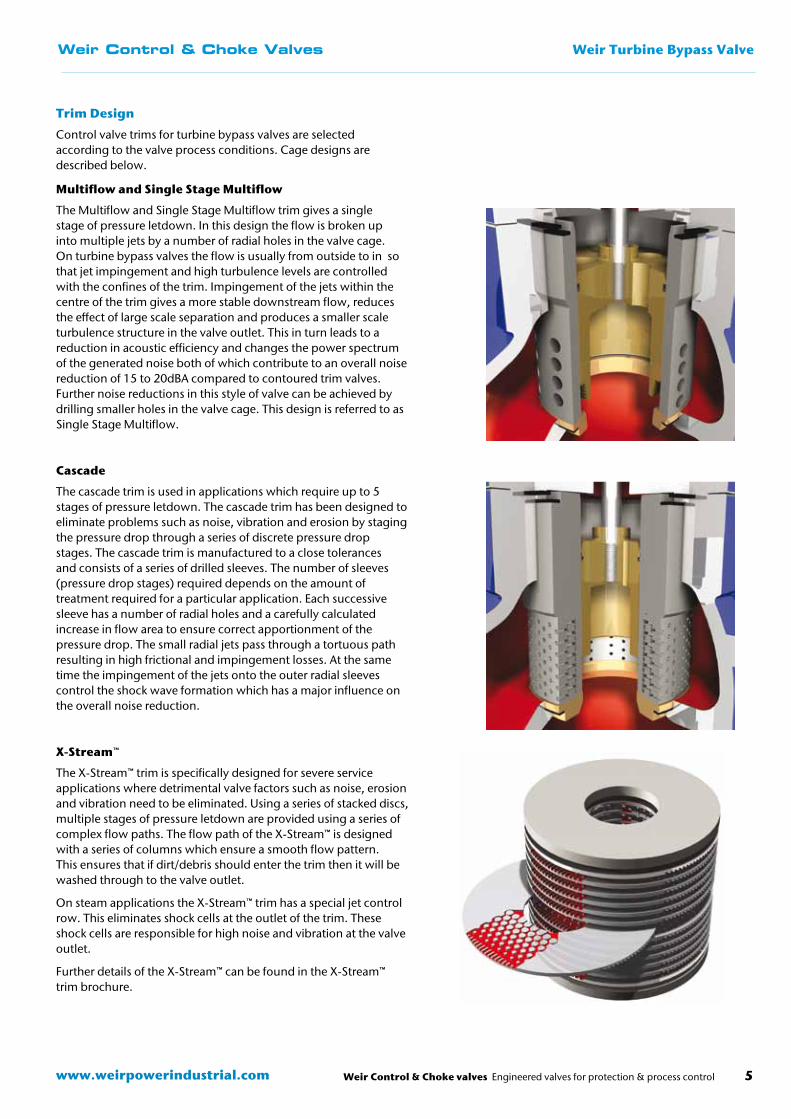
Multiflow and Single Stage Multiflow
The Multiflow and Single Stage Multiflow trim gives a single stage of pressure letdown. In this design the flow is broken up into multiple jets by a number of radial holes in the valve cage. On turbine bypass valves the flow is usually from outside to in so that jet impingement and high turbulence levels are controlled with the confines of the trim. Impingement of the jets within the centre of the trim gives a more stable downstream flow, reduces the effect of large scale separation and produces a smaller scale turbulence structure in the valve outlet. This in turn leads to a reduction in acoustic efficiency and changes the power spectrum of the generated noise both of which contribute to an overall noise reduction of 15 to 20dBA compared to contoured trim valves. Further noise reductions in this style of valve can be achieved by drilling smaller holes in the valve cage. This design is referred to as Single Stage Multiflow.
Cascade
The cascade trim is used in applications which require up to 5 stages of pressure letdown. The cascade trim has been designed to eliminate problems such as noise, vibration and erosion by staging the pressure drop through a series of discrete pressure drop stages. The cascade trim is manufactured to a close tolerances and consists of a series of drilled sleeves. The number of sleeves (pressure drop stages) required depends on the amount of treatment required for a particular application. Each successive sleeve has a number of radial holes and a carefully calculated increase in flow area to ensure correct apportionment of the pressure drop. The small radial jets pass through a tortuous path resulting in high frictional and impingement losses. At the same time the impingement of the jets onto the outer radial sleeves control the shock wave formation which has a major influence on the overall noise reduction.
X-Stream™
The X-Stream™ trim is specifically designed for severe service applications where detrimental valve factors such as noise, erosion and vibration need to be eliminated. Using a series of stacked discs, multiple stages of pressure letdown are provided using a series of complex flow paths. The flow path of the X-Stream™ is designed with a series of columns which ensure a smooth flow pattern. This ensures that if dirt/debris should enter the trim then it will be washed through to the valve outlet.
On steam applications the X-Stream™ trim has a special jet control row. This eliminates shock cells at the outlet of the trim. These shock cells are responsible for high noise and vibration at the valve outlet.
Further details of the X-Stream™ can be found in the X-Stream™ trim brochure.
www.weirpowerindustrial.comWeir Control & Choke valves Engineered valves for protection & process control6
Weir Turbine Bypass ValveWeir Control & Choke Valves
Class V Sealing
In order to maintain a condenser vacuum and ensure maximum power station efficiency turbine bypass valves often require a tight shut off which is referred to as Class V. Due to the high temperatures associated with a turbine bypass valve conventional resilient seals cannot be used, therefore many valve suppliers use pilot balanced trim designs. Depending on the stability of the process flow, pilot balanced trims can often generate trim instability and poor control.
Weir’s solution is to use a conventional balanced valve trim and install a metallic seal to prevent leakage between the valve plug and cage. The seal is pressure energised so that higher pressures across the valve trim result in increased sealing load and therefore tighter shut-offs.
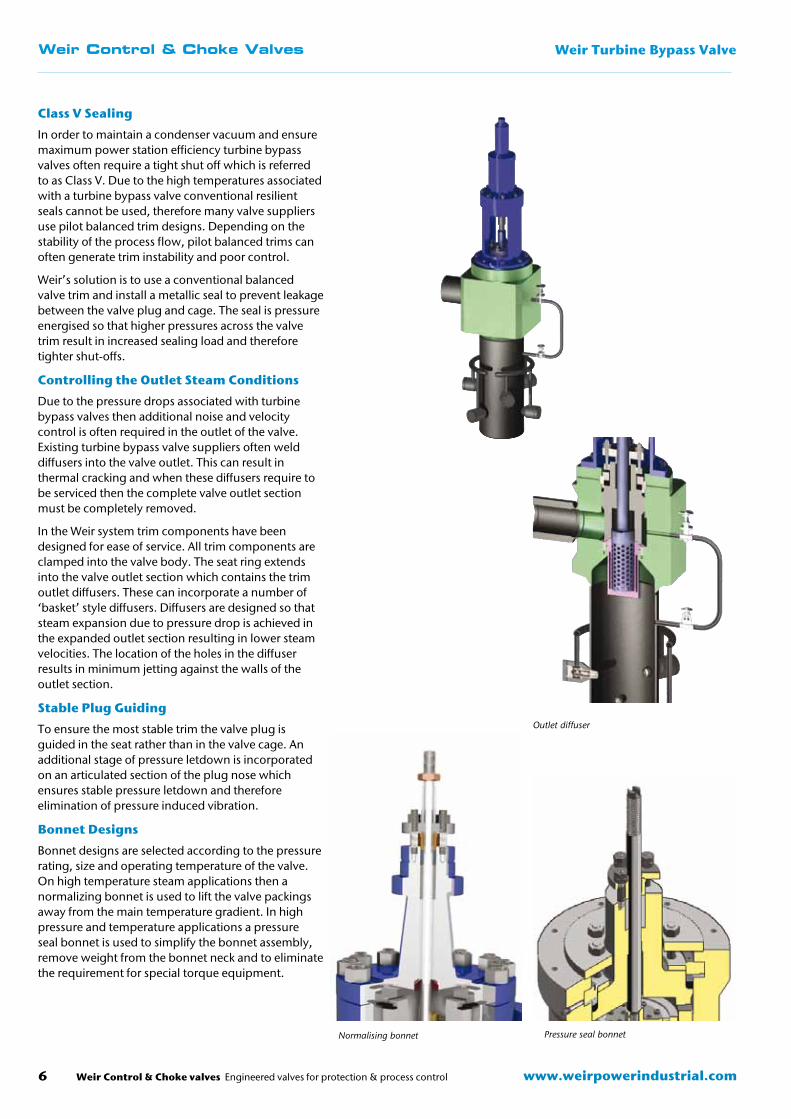
Controlling the Outlet Steam Conditions
Due to the pressure drops associated with turbine bypass valves then additional noise and velocity control is often required in the outlet of the valve. Existing turbine bypass valve suppliers often weld diffusers into the valve outlet. This can result in thermal cracking and when these diffusers require to be serviced then the complete valve outlet section must be completely removed.
In the Weir system trim components have been designed for ease of service. All trim components are clamped into the valve body. The seat ring extends into the valve outlet section which contains the trim outlet diffusers. These can incorporate a number of ‘basket’ style diffusers. Diffusers are designed so that steam expansion due to pressure drop is achieved in the expanded outlet section resulting in lower steam velocities. The location of the holes in the diffuser results in minimum jetting against the walls of the outlet section.
Stable Plug Guiding
To ensure the most stable trim the valve plug is guided in the seat rather than in the valve cage. An additional stage of pressure letdown is incorporated on an articulated section of the plug nose which ensures stable pressure letdown and therefore elimination of pressure induced vibration.
Bonnet Designs
Bonnet designs are selected according to the pressure rating, size and operating temperature of the valve. On high temperature steam applications then a normalizing bonnet is used to lift the valve packings away from the main temperature gradient. In high pressure and temperature applications a pressure seal bonnet is used to simplify the bonnet assembly, remove weight from the bonnet neck and to eliminate the requirement for special torque equipment.
Outlet diffuser
Normalising bonnet Pressure seal bonnet
Weir Control & Choke valves Engineered valves for protection & process control 7www.weirpowerindustrial.com
Weir Control & Choke Valves Weir Turbine Bypass Valve
Water Injection Options
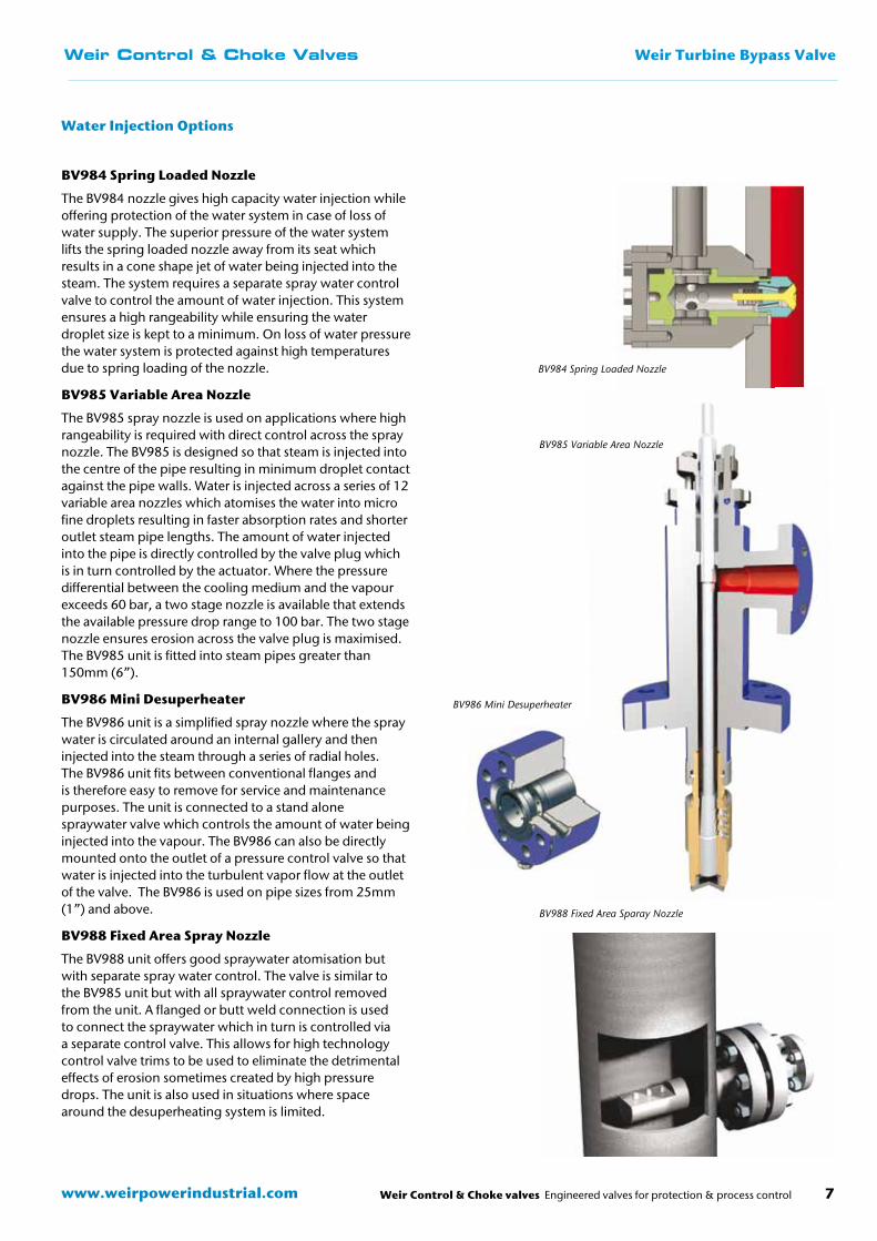
BV984 Spring Loaded Nozzle
The BV984 nozzle gives high capacity water injection while offering protection of the water system in case of loss of water supply. The superior pressure of the water system lifts the spring loaded nozzle away from its seat which results in a cone shape jet of water being injected into the steam. The system requires a separate spray water control valve to control the amount of water injection. This system ensures a high rangeability while ensuring the water droplet size is kept to a minimum. On loss of water pressure the water system is protected against high temperatures due to spring loading of the nozzle.
BV985 Variable Area Nozzle
The BV985 spray nozzle is used on applications where high rangeability is required with direct control across the spray nozzle. The BV985 is designed so that steam is injected into the centre of the pipe resulting in minimum droplet contact against the pipe walls. Water is injected across a series of 12 variable area nozzles which atomises the water into micro fine droplets resulting in faster absorption rates and shorter outlet steam pipe lengths. The amount of water injected into the pipe is directly controlled by the valve plug which is in turn controlled by the actuator. Where the pressure differential between the cooling medium and the vapour exceeds 60 bar, a two stage nozzle is available that extends the available pressure drop range to 100 bar. The two stage nozzle ensures erosion across the valve plug is maximised. The BV985 unit is fitted into steam pipes greater than 150mm (6”).
BV986 Mini Desuperheater
The BV986 unit is a simplified spray nozzle where the spray water is circulated around an internal gallery and then injected into the steam through a series of radial holes. The BV986 unit fits between conventional flanges and is therefore easy to remove for service and maintenance purposes. The unit is connected to a stand alone spraywater valve which controls the amount of water being injected into the vapour. The BV986 can also be directly mounted onto the outlet of a pressure control valve so that water is injected into the turbulent vapor flow at the outlet of the valve. The BV986 is used on pipe sizes from 25mm (1”) and above.
BV988 Fixed Area Spray Nozzle
The BV988 unit offers good spraywater atomisation but with separate spray water control. The valve is similar to the BV985 unit but with all spraywater control removed from the unit. A flanged or butt weld connection is used to connect the spraywater which in turn is controlled via a separate control valve. This allows for high technology control valve trims to be used to eliminate the detrimental effects of erosion sometimes created by high pressure drops. The unit is also used in situations where space around the desuperheating system is limited.
BV984 Spring Loaded Nozzle
BV985 Variable Area Nozzle
BV986 Mini Desuperheater
BV988 Fixed Area Sparay Nozzle
www.weirpowerindustrial.comWeir Control & Choke valves Engineered valves for protection & process control8
Weir Turbine Bypass ValveWeir Control & Choke Valves
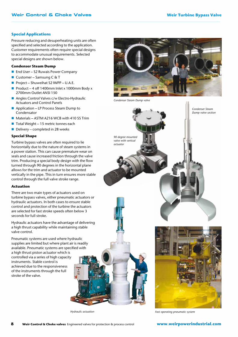
Special Applications
Pressure reducing and desuperheating units are often specified and selected according to the application. Customer requirements often require special designs to accommodate unusual requirements. Selected special designs are shown below.
Condenser Steam Dump � End User – S2 Ruwais Power Company
� Customer – Samsung C & T
� Project – Shuweihat S2 IWPP – U.A.E.
� Product – 4 off 1400mm Inlet x 1000mm Body x 2700mm Outlet ANSI 150
� Angles Control Valves c/w Electro-Hydraulic Actuators and Control Panels
� Application – LP Process Steam Dump to Condensator
� Materials – ASTM A216 WCB with 410 SS Trim
� Total Weight – 15 metric tonnes each
� Delivery – completed in 28 weeks
Special Shape
Turbine bypass valves are often required to lie horizontally due to the nature of steam systems in a power station. This can cause premature wear on seals and cause increased friction through the valve trim. Producing a special body design with the flow turned through 90 degrees in the horizontal plane allows for the trim and actuator to be mounted vertically in the pipe. This in turn ensures more stable control through the full valve stroke range.
Actuation
There are two main types of actuators used on turbine bypass valves, either pneumatic actuators or hydraulic actuators. In both cases to ensure stable control and protection of the turbine the actuators are selected for fast stroke speeds often below 3 seconds for full stroke.
Hydraulic actuators have the advantage of delivering a high thrust capability while maintaining stable valve control.
Pneumatic systems are used where hydraulic supplies are limited but where plant air is readily available. Pneumatic systems are specified with a high thrust piston actuator which is controlled via a series of high capacity instruments. Stable control is achieved due to the responsiveness of the instruments through the full stroke of the valve.
Condenser Steam Dump valve
Condenser Steam Dump valve section
90 degree mounted valve with vertical actuator
Hydraulic actuation Fast operating pneumatic system
Weir Control & Choke valves Engineered valves for protection & process control 9www.weirpowerindustrial.com
Weir Control & Choke Valves Weir Turbine Bypass Valve
Initial Sizing of Desuperheaters
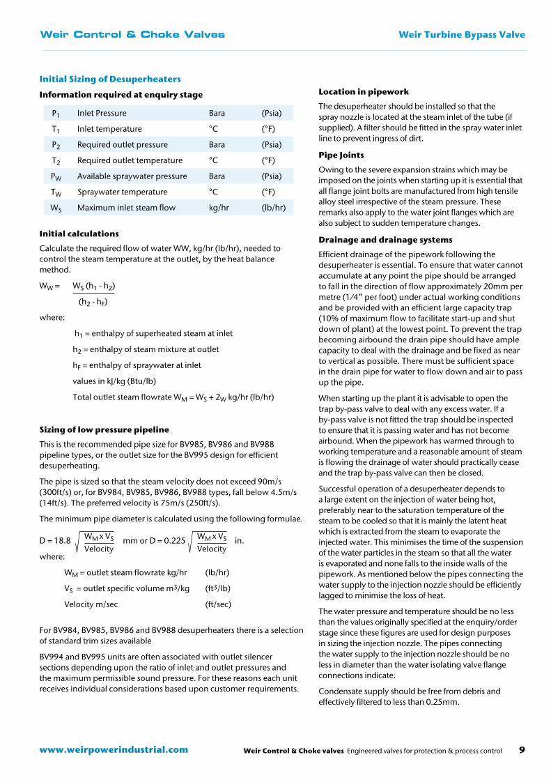
Information required at enquiry stage
Initial calculations
Calculate the required flow of water WW, kg/hr (lb/hr), needed to control the steam temperature at the outlet, by the heat balance method.
WW = WS (h1 - h2)
(h2 - hF)
where:
h1 = enthalpy of superheated steam at inlet
h2 = enthalpy of steam mixture at outlet
hF = enthalpy of spraywater at inlet
values in kJ/kg (Btu/lb)
Total outlet steam flowrate WM = WS + 2W kg/hr (lb/hr)
Sizing of low pressure pipeline
This is the recommended pipe size for BV985, BV986 and BV988 pipeline types, or the outlet size for the BV995 design for efficient desuperheating.
The pipe is sized so that the steam velocity does not exceed 90m/s (300ft/s) or, for BV984, BV985, BV986, BV988 types, fall below 4.5m/s (14ft/s). The preferred velocity is 75m/s (250ft/s).
The minimum pipe diameter is calculated using the following formulae.
For BV984, BV985, BV986 and BV988 desuperheaters there is a selection of standard trim sizes available
BV994 and BV995 units are often associated with outlet silencer sections depending upon the ratio of inlet and outlet pressures and the maximum permissible sound pressure. For these reasons each unit receives individual considerations based upon customer requirements.
D = 18.8 mm or D = 0.225 in.
where:
WM = outlet steam flowrate kg/hr (lb/hr)
VS = outlet specific volume m3/kg (ft3/lb)
Velocity m/sec (ft/sec)
Location in pipework
The desuperheater should be installed so that the spray nozzle is located at the steam inlet of the tube (if supplied). A filter should be fitted in the spray water inlet line to prevent ingress of dirt.
Pipe Joints
Owing to the severe expansion strains which may be imposed on the joints when starting up it is essential that all flange joint bolts are manufactured from high tensile alloy steel irrespective of the steam pressure. These remarks also apply to the water joint flanges which are also subject to sudden temperature changes.
Drainage and drainage systems
Efficient drainage of the pipework following the desuperheater is essential. To ensure that water cannot accumulate at any point the pipe should be arranged to fall in the direction of flow approximately 20mm per metre (1⁄4” per foot) under actual working conditions and be provided with an efficient large capacity trap (10% of maximum flow to facilitate start-up and shut down of plant) at the lowest point. To prevent the trap becoming airbound the drain pipe should have ample capacity to deal with the drainage and be fixed as near to vertical as possible. There must be sufficient space in the drain pipe for water to flow down and air to pass up the pipe.
When starting up the plant it is advisable to open the trap by-pass valve to deal with any excess water. If a by-pass valve is not fitted the trap should be inspected to ensure that it is passing water and has not become airbound. When the pipework has warmed through to working temperature and a reasonable amount of steam is flowing the drainage of water should practically cease and the trap by-pass valve can then be closed.
Successful operation of a desuperheater depends to a large extent on the injection of water being hot, preferably near to the saturation temperature of the steam to be cooled so that it is mainly the latent heat which is extracted from the steam to evaporate the injected water. This minimises the time of the suspension of the water particles in the steam so that all the water is evaporated and none falls to the inside walls of the pipework. As mentioned below the pipes connecting the water supply to the injection nozzle should be efficiently lagged to minimise the loss of heat.
The water pressure and temperature should be no less than the values originally specified at the enquiry/order stage since these figures are used for design purposes in sizing the injection nozzle. The pipes connecting the water supply to the injection nozzle should be no less in diameter than the water isolating valve flange connections indicate.
Condensate supply should be free from debris and effectively filtered to less than 0.25mm.
P1 Inlet Pressure Bara (Psia)
T1 Inlet temperature °C (°F)
P2 Required outlet pressure Bara (Psia)
T2 Required outlet temperature °C (°F)
PW Available spraywater pressure Bara (Psia)
TW Spraywater temperature °C (°F)
WS Maximum inlet steam flow kg/hr (lb/hr)
WM x VS
Velocity
WM x VS
Velocity

NotesWeir Control & Choke Valves
www.weirpowerindustrial.comWeir Control & Choke valves Engineered valves for protection & process control10

Weir Control & Choke Valves Notes
Weir Control & Choke valves Engineered valves for protection & process control 11www.weirpowerindustrial.com
TBV 2-0312
Copyright © 2012 Weir Valves & Controls UK Ltd.
Weir Valves & Controls UK Ltd
Britannia House Huddersfield Road Elland, West Yorkshire HX5 9JR England
Tel: +44 (0) 1422 282 000 Fax: +44 (0) 1422 282 100 Email: [email protected] www.weirvalve.com
Britannia House Huddersfield Road Elland, West Yorkshire HX5 9JR England
Tel: +44 (0) 1422 282 000 Fax: +44 (0) 1422 282 100 Email: [email protected] www.weirvalve.com
Hopkinsons
Britannia House Huddersfield Road Elland, West Yorkshire HX5 9JR England
Tel: +44 (0) 1422 282 000Fax: +44 (0) 1422 282 100Email: [email protected]
Blakeborough Controls
Batley Valve
Britannia House Huddersfield Road Elland, West Yorkshire HX5 9JR England
Tel: +44 (0) 1422 282 000 Fax: +44 (0) 1422 282 100 Email: [email protected] www.weirvalve.com
Britannia House Huddersfield Road Elland, West Yorkshire HX5 9JR England
Tel: +44 (0) 1422 282 000 Fax: +44 (0) 1422 282 100 Email: [email protected] www.weirvalve.com
Excellent Engineering Solutions
Excellent Engineering Solutions
Excellent Engineering Solutions
Excellent Engineering Solutions
ExcellentEngineeringSolutions
Weir Control & Choke Valves
East Kilbride, UK
Elland, UK
Fort St. John, Canada
Toronto, CanadaMontréal, Canada
Calgary, Canada
Boston, USA
Singapore, Malaysia
Alloa, UK
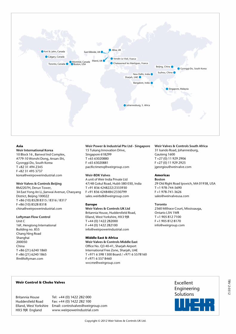
AsiaWeir International Korea10 Block 16 , Banwol Ind Complex, #779-10 Wonshi Dong, Ansan-Shi, Gyonggi-Do, South KoreaT +82 31 494 2345 F +82 31 495 3737 [email protected]
Weir Valves & Controls BeijingRM2207H, Derun Tower, 3A East Yong An Li, Jianwai Avenue, Chaoyang District, Beijing 100022T +86 (10) 8528 8315 / 8316 / 8317 F +86 (10) 8528 8318 [email protected] Loftyman Flow ControlUnit C16F, Hengtong InternationalBuilding no. 855Chang Ning RoadShanghai200050ChinaT +86 (21) 6240 1860F +86 (21) 6240 [email protected]
Weir Power & Industrial Pte Ltd - Singapore15 Tukang Innovation Drive, Singapore 618299T +65 63020880 F +65 [email protected] Weir-BDK ValvesA unit of Weir India Private Ltd47/48 Gokul Road, Hubli-580 030, IndiaT +91 836 4248222/2333930 F +91 836 4248484/2330799 [email protected]
EuropeWeir Valves & Controls UK LtdBritannia House, Huddersfield Road, Elland, West Yorkshire, HX3 9JRT +44 (0) 1422 282000 F +44 (0) 1422 282100 [email protected]
Middle East & AfricaWeir Valves & Controls Middle EastOffice No. Q3 40-41, Sharjah Airport International Free Zone, Sharjah, UAET +971 6 598 1300 Board / +971 6 5578160 F +971 6 557 8460 [email protected]
Weir Valves & Controls South Africa31 Isando Road, Johannesburg, Gauteng 1600T +27 (0) 11 929 2906 F +27 (0) 11 929 2925 [email protected]
AmericasBoston29 Old Right Road Ipswich, MA 01938, USAT +1 978-744-5690 F +1 978-741-3626 [email protected]
Toronto2360 Millrace Court, Mississauga, Ontario L5N 1WRT +1 905 812 7100 F +1 905 812 8170 [email protected]
Related Documents